VF-102G-KIT - AV amplifier Planet - Free user manual and instructions
Find the device manual for free VF-102G-KIT Planet in PDF.

User questions about VF-102G-KIT Planet
0 question about this device. Answer the ones you know or ask your own.
Ask a new question about this device
Download the instructions for your AV amplifier in PDF format for free! Find your manual VF-102G-KIT - Planet and take your electronic device back in hand. On this page are published all the documents necessary for the use of your device. VF-102G-KIT by Planet.
USER MANUAL VF-102G-KIT Planet
4-in-1 Video over Gigabit Fiber Bundle Kit
VF-101G/102G/106G-KIT
User's Manual
Copyright
Copyright © 2017 by PLANET Technology Corp. All rights reserved. No part of this publication may be reproduced, transmitted, transcribed, stored in a retrieval system, or translated into any language or computer language, in any form or by any means, electronic, mechanical, magnetic, optical, chemical, manual or otherwise, without the prior written permission of PLANET.
PLANET makes no representations or warranties, either expressed or implied, with respect to the contents hereof and specifically disclaims any warranties, merchantability or fitness for any particular purpose. Any software described in this manual is sold or licensed "as is". Should the programs prove defective following their purchase, the buyer (and not PLANET, its distributor, or its dealer) assumes the entire cost of all necessary servicing, repair, and any incidental or consequential damages resulting from any defect in the software. Further, PLANET reserves the right to revise this publication and to make changes from time to time in the contents hereof without obligation to notify any person of such revision or changes.
All brand and product names mentioned in this manual are trademarks and/or registered trademarks of their respective holders.
Federal Communication Commission Interference Statement
This device has been tested and found to comply with the limits for a Class B digital device, pursuant to Part 15 of FCC Rules. These limits are designed to provide reasonable protection against harmful interference in a residential installation. This device generates, uses, and can radiate radio frequency energy and, if not installed and used in accordance with the instructions, may cause harmful interference to radio communications. However, there is no
guarantee that interference will not occur in a particular installation. If this device does cause harmful interference to radio or television reception, which can be determined by turning the device off and on, the user is encouraged to try to correct the interference by one or more of the following measures:
- Reorient or relocate the receiving antenna.
- Increase the separation between the device and receiver.
- Connect the device into an outlet on a circuit different from that to which the receiver is connected.
- Consult the dealer or an experienced radio technician for help.
FCC Caution
To assure continued compliance, use only shielded interface cables when connecting to computer or peripheral devices. Any changes or modifications not expressly approved by the party responsible for compliance could void the user's authority to operate the device.
This device complies with Part 15 of the FCC Rules. Operation is subject to the following two conditions: (1) This device may not cause harmful interference, and (2) this device must accept any interference received, including interference that may cause undesired operation.
Federal Communication Commission (FCC) Radiation Exposure Statement
This device complies with FCC radiation exposure set forth for an uncontrolled environment. In order to avoid the possibility of exceeding the FCC radio frequency exposure limits, human proximity to the antenna shall not be less than 20 cm (8 inches) during normal operation.
CE Mark Warning
CE Warning: This equipment is a Class B product. In a domestic environment, this product may cause radio interference, in which case the user may be required to take adequate measures.
Safety Instructions
This device is designed with the utmost care for the safety of those who install and use it. However, special attention must be paid to the dangers of electric shock and static electricity when working with electrical device. All guidelines of this and the computer manufacturing must therefore be allowed at all times to ensure the safe use of the device.
National Restrictions
This device is intended for home and office use in all EU countries (and other countries following the EMC directive 2014/30/EU and LVD directive 2014/35/EU).
WEEE Regulation
To avoid the potential effects on the environment and human health as a result of the presence of hazardous substances in electrical and electronic device, end users of electrical and electronic device should understand the meaning of the crossed-out wheeled bin symbol. Do not dispose of WEEE as unsorted municipal waste and have to collect such WEEE separately.
Revision
User's Manual of 1-channel 4-in-1 Video over Gigabit Fiber Bundle Kit (VF-101G/102G/106G-T + VF-101G/102G/106G-R)
Model: VF-101G/102G/106G-KIT
Rev: 1.0 (June, 2017)
Part No. EM-VF-101G/102G/106G-KIT_v1.0
Table of Contents
Chapter 1. Product Introduction ...... 6
1.1 Package Contents....6
1.2 Product Description 6
1.3 Application....8
1.4 Product Features....10
1.5 Product Specifications.... 10
Chapter 2. Hardware Description.... 13
2.1 Front Panel.... 13
2.2 Rear Panel....14
Chapter 3. Installation.... 16
3.1 Limitation 16
3.2 Preparation before Installing....16
3.3 Stand-alone Installation 17
3.4 Optional Chassis Installation.... 18
3.5 Optional DIN-rail Installation 19
Chapter 4. Precautions....21
Chapter 5. Power Information....22
Chapter 6. Troubleshooting....23
Chapter 1. Product Introduction
1.1 Package Contents
Check the contents of your package for the following parts:
- VF-101G/102G/106G-T - Video over Fiber Media Converter (Transmitter) x 1
- VF-101G/102G/106G-R - Video over Fiber Media Converter (Receiver) x 1
- 5V Power Adapter x 2
- User's Manual x 1

Note
If any of the above items are missing, please contact your dealer immediately.
1.2 Product Description
Long Distance Analog Surveillance Transmission System
To deploy AHD/CVI/TVI/CVBS analog camera in a remote place efficiently and provide high video quality and reliable signal, PLANET has developed the video over Gigabit fiber media converter kit, VF-101G/102G/106G-KIT, which is ideal for extending the distance and signal conversion by transmitting the AHD/CVI/TVI/CVBS video and data over the fiber-optic cable. Adopting the intelligent encoding/decoding technology and with the compact box, the VF-101G/102G/106G-KIT video over fiber media converter enables videos to be delivered in high quality over a distance of up to 20km long.

flowchart
graph TD
    A["A HD"] -->|Data Flow| D["Central Device"]
    B["TV1"] -->|Data Flow| D
    C["CV1"] -->|Data Flow| D
    E["CVBS"] -->|Data Flow| D
Fiber Optic Communication for Video and Serial Data
This Video over Gigabit Fiber Converter kit consists of a Video Transmitter and a Video Receiver:
- VF-101G/102G/106G-T: 1-channel Video over Gigabit Fiber Transmitter
- VF-101G/102G/106G-R: 1-channel Video over Gigabit Fiber Receiver
The VF-101G/102G/106G-KIT is a digital fiber-optic transmission system that brings users a cost-effective solution for transmission of 1 channel uncompressed digital video and one reverse RS485 async data over one single fiber cable. The VF-101G/102G/106G-KIT is an adjustable free device providing high-quality and real-time video transmission. It can be widely used in intelligent transportation systems (ITS), traffic surveillance, security monitoring, automation control, intelligent residential districts, etc.

flowchart
graph LR
    A["1080p Analog Camera"] -->|Coax| B["VF-101G/102G/106G-T Transmitter"]
    B -->|Up to 20km| C["VF-101G/102G/106G-R Receiver"]
    C -->|Coax| D["HDVR / Monitor"]
    style A fill:#f9f,stroke:#333
    style B fill:#ccf,stroke:#333
    style C fill:#cfc,stroke:#333
    style D fill:#fcc,stroke:#333
    note right of B: "Up to 20km"
    note right of C: "Video Line"
    note left of A: "Gigabit Fiber-optic"

flowchart
graph LR
    A["Speed Dome"] -->|Coax| B["VF-101G/102G/106G-T Transmitter"]
    B -->|Up to 20km| C["VF-101G/102G/106G-R Receiver"]
    C -->|Coax| D["HDVR / Monitor"]
    C -->|Video Line| E["Control Keyboard"]
    B -->|RS485| F["Gigabit Fiber-optic"]
    C -->|RS485| G["Video Line"]
Easy Installation
Simply by Plug and Play, the installation of the VF-101G/102G/106G-KIT media conversion is quite easy. They can be used as a stand-alone unit or as a slide-in module to the PLANET Media Converter Chassis (MC-700, MC-1500 and MC-1500R). When working with the media converter chassis, the media converter chassis provides DC power to VF-101G/102G/106G-T or VF-101G/102G/106G-R to maintain the video over fiber-optic transmission system at the central location.

text_image
Plug & Play Stable and Easy to Use1.3 Application
The VF-101G/102G/106G-KIT consists of 1 channel video over fiber optic transceiver and receiver to transmit video and RS485
signal through a reliable single mode or single fiber link. It is an ideal cost-effective solution for surveillance system that requires high display quality and high-performance signal transmission over long distances. The VF-101G/102G/106G-KIT can be installed easily by way of “Plug and Play”, meaning the operator does not need to configure the pair of the video over fiber transmission in advance.
The transmitter and receiver can work as standalone or can be slotted into a rack-mountable media converter chassis. The flexible and maintenance-free design fits in with different installation environments. With one VF-101G/102G/106G-KIT, video cameras can be deployed over a distance of up to 20km, which ideally suits the following applications:
● Intelligent Transportation Systems (ITS)
- Toll Collection
- Traffic Surveillance
● Air Traffic Management (ATM)
- Rail Signaling
● Perimeter Alarms and Area Monitors
● Telemedicine and Teleconference
- Industrial Surveillance
- Intelligent Buildings

flowchart
graph LR
    A["Camera"] -->|Coax Video| B["VF-101G-T"]
    C["Camera"] -->|Coax Video| D["VF-102G-T"]
    E["Speed Dome"] -->|Coax Video/SSS| F["VF-106G-T"]
    B --> G["Media Converter Chassis"]
    D --> G
    F --> G
    G --> H["HDVR / Monitor"]
    G --> I["Control Keyboard"]
    style G fill:#f9f,stroke:#333,stroke-width:2px
    note right of G
        Gigabit Fiber-optic
        Video Line
        RS485
    end
1.4 Product Features
● Compliant with hybrid video (AHD/TVI/CVI/CVBS)
● Long-distance data transmission of 20km
● Status indication for power supply, optical signal and video
● High-speed synchronous digital transmission technology
● Guarantees safe transmission under poor electromagnetic environment
● Video and data transmission over Gigabit fiber optic cable
● PAL, NTSC, SECAM compatible
● Data type: RS485
● 8-/10-bit digital Video Signal sampling
- Standalone or work with PLANET MC-700/1500/1500R media converter chassis
- Compact size, wall-mount design, easy installation
1.5 Product Specifications
| Model VF-101G-KIT VF-102G-KIT VF-106G-KIT | ||
| Video Characteristics | ||
| Video Channel 1 channel | bi-direction | |
| Signal Mode NTSC/PAL/SECAM | ||
| Video Connector BNC | ||
| Supported Video Type | 1080p: AHD/TVI/CVI480p: CVBS | |
| Video Input/Output Impedance | 75ohm/unbalanced interface | |
| Video Input/Output Voltage | 1.0 Vpp/typical peak-to-peak value | |
| Video Bandwidth 60MHz | ||
| Video Digital Bit Width 8/10 bit | |||
| Differential Gain(DG) < | 1.3% (typical value) | ||
| Differential Phase(DP) < | 1.3° (typical value) | ||
| SNR Weighted >67dB (typical value) | |||
| Data Interface | |||
| Data Channel 1 channel | |||
| Physical Protocol RS485 | |||
| Operation Mode Simplex | |||
| Data Connector 3 Pin terminal block with screw clamps | |||
| Data Rate DC-115.2Kbps | |||
| Bit Error Rate (BER) < 10ns | |||
| Optical Interface | |||
| Optical Connector ST FC | WDM-SC | ||
| Distance 20km for single mode | |||
| Optical Wavelength | VF-101G-T VF-102G-T VF-106G-T | ||
| TX: 1310nm, RX: 1550nm | TX: 1310nm, RX: 1550nm | TX: 1310nm, RX: 1550nm | |
| VF-101G-R | VF-102G-R | VF-106G-R | |
| TX: 1550nm, RX: 1310nm | TX: 1550nm, RX: 1310nm | TX: 1550nm, RX: 1310nm | |
| Launch Power (dBm) Max.: 0, Min.: -9 | |||
| Receive Sensitivity (dBm) | -26 | ||
| Max. Input Power (dBm) | -3 | ||
| Cable | 9/125μm single mode cable | ||
| Hardware Specifications | |||
| LED Indicators | ●Power●Video●Link (fiber optic) | ||
| Dimensions(W x D x H) | 94 x 70 x 26 mm | ||
| Weight 200g | |||
| Power Requirement 5V DC, 2A | |||
| Power Consumption 4.8 | watts (maximum) | ||
| Mechanical Metal | |||
| Installation | Wall-mountable, DIN-rail (with optional kit), chassis installation (with optional chassis) | ||
| Compatible Converter Chassis | MC-700/MC-1500/MC-1500R | ||
| Standards Conformance | |||
| Regulatory Compliance | FCC, CE | ||
| Environment | |||
| Operating | Temperature: -25 ~ 70 degrees CRelative Humidity: 0 ~ 95%(non-condensing) | ||
| Storage | Temperature: -30 ~ 80 degrees CRelative Humidity: 0 ~ 95%(non-condensing) | ||
| Standard Accessories | |||
| Packet Contents | VF-101G/102G/106G-T x 1VF-101G/102G/106G-R x 1User's manual x 15V power adapter x 2 | ||
Chapter 2. Hardware Description
2.1 Front Panel
The front panel of the VF-101G-T/VF-101G-R comes with two fiber optic interfaces and one video socket, while those of the VF-102G-T/VF-102G-R and VF-106G-T/VF-106G-R each have one fiber optic interface and one video socket. For the VF-101G/102G/106G-T and VF-101G/102G/106G-R, With the reverse data connector, the RS485 data port of the VF-101G/102G/106G-T or VF-101G/102G/106G-R can be connected to the user's interface.

text_image
OPTIC LNK GND PWR VIDEO Videover Gigabit Fiber Converter RS485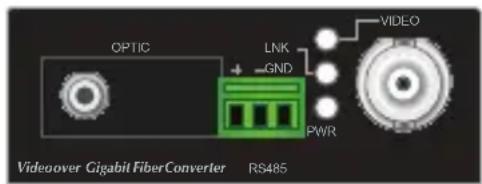
text_image
OPTIC LINK GND PWR VIDEO Videover Gigabit FiberConverter RS485VF-101G-T/VF-101G-R VF-102G-T/VF-102G-R

text_image
OPTIC LNK GND PWR VIDEO Video over Gigabit FiberConverter RS485VF-106G-T/VF-106G-R
- Video Interface
| Video Connection | Connect the video signal to or from the product through a 75Ω coax cable with BNC plug. |
| Async-data Connection | ●Connect the output data port (e.g. TX+ and TX-) of the other controlled device to the RX+ and RX- of the RX. ●Connect the input data port (e.g. RX+ and RX- of the other controlled device to the TX+ and TX- of the TX. ●GND in both TX and RX should be connected directly to user's equipment. |
| Fiber Connection | Connect the fiber-optic cable pigtail to the product's fiber port. |
- LED Definition
| LED Color Function | ||
| PWR Green Lights to indicate that the device is powered. | ||
| VIDEO Green Lights when the device receives video signal. | ||
| LNK Green | Lights when the fiber connection is established. | |
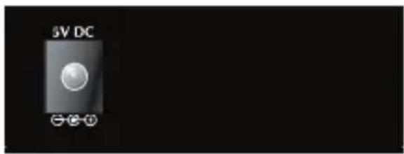
2.2 Rear Panel
The rear panel of the converter has one DC jack, which accepts an input power of 5V DC at 2A.
text_image
5V DC ①②③④- Power Supply
| Power supply | |
| Output 5V DC, 2A | |
Note
-
The device is a power-required device, meaning it will not work till it is powered. If your networks should be active all the time, please consider using UPS (Uninterrupted Power Supply) for your device. It will prevent you from network data loss or network downtime.
-
In some areas, installing a surge suppression device may also help to protect your converter from being damaged by unregulated surge or current to the converter or the power adapter.
- Fiber Interface
| Item Description | |
| FIBER/OPT FC-type fiber interface. | |

Note
After the VF-101G/102G/106G-KIT is powered on, wait for at least 15 seconds before connecting the connector to the optical fiber port or else the connector may be damaged or you may get an electric shock.
Chapter 3. Installation
This section describes how to install your VF-101G/102G/106G-KIT Video over Fiber and make connections to the converter. Please read the following sections and perform the procedures in the order being presented. The hardware installation of PLANET VF-101G/102G/106G-KIT Video over Fiber Converter does not need software configuration. To install your VF-101G/102G/106G-KIT on a desktop or shelf, check the following sections.
3.1 Limitation
The converter does not require any software configuration. Users can immediately use any feature of this product simply by plugging in the cable and powering it on. There is some key limitation on the video over fiber converter. Please check the following items:
- The device is used for Point-to-Point connection only (transmitter to receiver) and allows video and data to work on the same optical fiber patch cord.
- The BNC connector supports 75 ohm cable. The maximum distance will change by the quality of coaxial cables.
3.2 Preparation before Installing
In order to ensure your normal use, please make sure that you are using the right optical path, right signal, good power grounding, and so on. We guarantee all of our products are subject to strict test and aging, and we simulate field environment operation tests. Please contact us if there is any problem.
(1) Please carefully read the user manual of the product before installing.
(2) Please carefully read the safety instructions.
(3) Optical transceiver equipment shall not be disassembled by anyone without authorization.
(4) Check the product model tag stuck outside the cabinet to prevent incorrect installation.
(5) The relation of the video of optical transmitter and optical receiver is one-to-one.
3.3 Stand-alone Installation
To install a pair of VF-101G/102G/106G-T and VF-101G/102G/106G-R stand-alone on a desktop or shelf, simply complete the following steps:
(1) Turn off the power of the analog camera/monitor to which the VF-101G/102G/106G-T or VF-101G/102G/106G-R will be attached.
(2) VF-101G/102G/106G-T (Transmitter): Connect coaxial cable from analog camera to video BNC port of the VF-101G/102G/106G-T.
(3) Attach the suitable single mode fiber cable from the VF-101G/102G/106G-T to VF-101G/102G/106G-R in the remote side.

Note
After the VF-101G/102G/106G-KIT is powered on, wait for at least 15 seconds before connecting the connector to the optical fiber port or else the connector may be damaged or you may get an electric shock.
(4) VF-101G/102G/106G-R (Receiver): Connect coaxial cable from monitor/HDVR to Video BNC port of the VF-101G/102G/106G-R.
(5) Connect the 5V DC power adapter to the VF-101G/102G/106G-T and VF-101G/102G/106G-R, and make sure that the power is on and the link LED is lit.
(6) Turn on the power of the analog camera/monitor; the video LED should be lit when all cables are connected.

flowchart
graph LR
    A["Speed Dome"] -->|Coax Video RS485| B["Transmitter"]
    B --> C["Up to 20km"]
    C --> D["Receiver"]
    D --> E["Coax Video HDVR / Monitor"]
    D --> F["Control Keyboard"]
    style A fill:#f9f,stroke:#333
    style B fill:#ccf,stroke:#333
    style C fill:#cfc,stroke:#333
    style D fill:#fcc,stroke:#333
    style E fill:#ffc,stroke:#333
    style F fill:#fcc,stroke:#333
    linkStyle 0 stroke:#ff0,stroke-width:2px
    linkStyle 1 stroke:#ff0,stroke-width:2px
    linkStyle 2 stroke:#ff0,stroke-width:2px
    linkStyle 3 stroke:#ff0,stroke-width:2px
    linkStyle 4 stroke:#ff0,stroke-width:2px
    linkStyle 5 stroke:#ff0,stroke-width:2px
    linkStyle 6 stroke:#ff0,stroke-width:2px
    linkStyle 7 stroke:#ff0,stroke-width:2px
    linkStyle 8 stroke:#ff0,stroke-width:2px
    linkStyle 9 stroke:#ff0,stroke-width:2px
    linkStyle 10 stroke:#ff0,stroke-width:2px
    linkStyle 11 stroke:#ff0,stroke-width:2px
    linkStyle 12 stroke:#ff0,stroke-width:2px
    linkStyle 13 stroke:#ff0,stroke-width:2px
    linkStyle 14 stroke:#ff0,stroke-width:2px
    linkStyle 15 stroke:#ff0,stroke-width:2px
    linkStyle 16 stroke:#ff0,stroke-width:2px
    linkStyle 17 stroke:#ff0,stroke-width:2px
    linkStyle 18 stroke:#ff0,stroke-width:2px
    linkStyle 19 stroke:#ff0,stroke-width:2px
    linkStyle 20 stroke:#ff0,stroke-width:2px
3.4 Optional Chassis Installation
To install the Video over Fiber Converter in a 10-inch or 19-inch Converter Chassis with standard rack, follow the instructions described below.
(1) Place your Converter Chassis on a hard flat surface, with the front panel positioned toward your front side.
(2) Carefully slide in the module until it is fully and firmly fitted into the slot of the Converter Chassis.
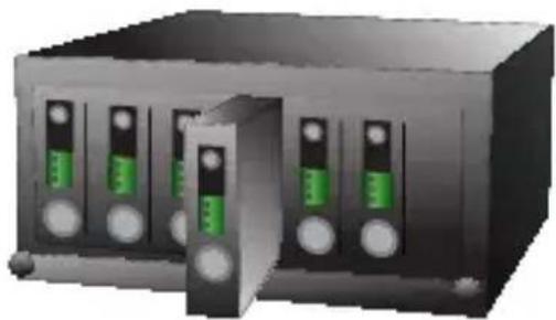
natural_image
3D rendering of a server rack with multiple drive bays and a central access port (no text or symbols visible)(3) Attach a rack-mount bracket to each side of the Converter Chassis with supplied screws attached to the package.
(4) After the brackets are attached to the Converter Chassis, use suitable screws to securely attach the brackets to the rack.
(5) Connect the video and fiber cabling, and supply power to your Converter Chassis.
3.5 Optional DIN-rail Installation
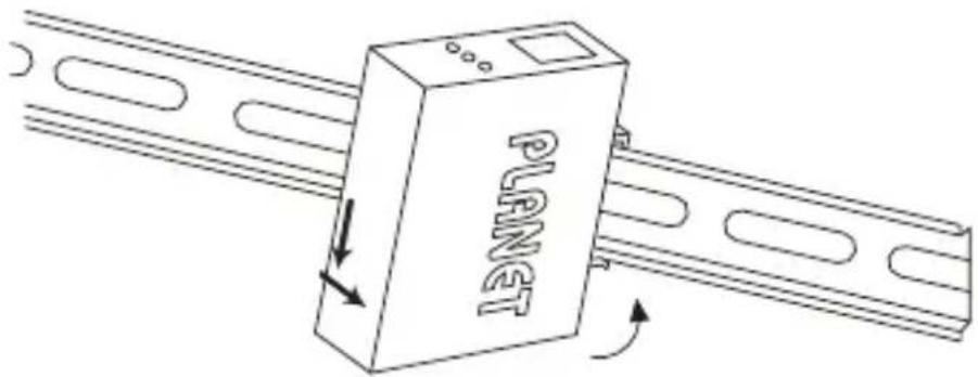
There are two DIN-rail holes on the left side of the VF-101G/102G/106G-T or VF-101G/102G/106G-R that allows the converter to be easily installed with DIN-rail mounting. PLANET optional DIN-rail mounting kit - RKE-DIN - can be ordered separately. When the wall mount application needs to be replaced with the DIN-rail application for the VF-101G/102G/106G-T or VF-101G/102G/106G-R, please refer to the following figures to attach the DIN-rail to the converter. To hang the VF-101G/102G/106G-T or VF-101G/102G/106G-R on the DIN-rail, follow the steps below:
(1) Screw the DIN-rail on the VF-101G/102G/106G-T or VF-101G/102G/106G-R.

text_image
PLANT(2) Lightly press and push the DIN-rail into the track.
text_image
PLANT(3) Check whether the DIN-rail is tightly on the track.

natural_image
Line drawing of a 3D industrial device labeled 'PLA' connected to a rail, showing no text or symbols beyond the label.
Note
You must use the screws supplied with the mounting brackets. Damage caused to the parts by using incorrect screws would invalidate your warranty.
Chapter 4. Precautions
(1) Insert fiber correctly into the fiber interface; try not to apply too much force to avoid breaking the fiber. The rolling diameter cannot be less than 20cm.
(2) Fasten the retaining screw after connecting terminal blocks.
(3) Do not remove the dust cap before installation. Make sure to prevent dirt and other things from getting into port or else the loss of optical signal will be increased and the transmission quality will be affected.
(4) Note that optical transceiver matches well when installing device so as to avoid work obstruction because of a different optical power, data interface and transmission distance. Pay attention to the differences of transmitter and receiver.
(5) Data interface is terminal block. To ensure good contact, it is required to insert interface after thinning. Please use good-quality stranded and shielded copper core, such as Belden, etc.
Chapter 5. Power Information
The central post of the power jack of the VF-101G/102G/106G-T or VF-101G/102G/106G-R measures 2.5mm, and +5V DC/2A power input is required. It conforms to the bundled AC-DC adapter and Planet's Media Converter Chassis. If you have a power connection issue, please contact your local sales representative.
Please keep the AC-DC adapter as a spare item when your VF-101G/102G/106G is installed to a Media Converter Chassis.

2.5mm
DC Receptacle 2.5mm
+5V for each slot

DC receptacle is 2.5mm wide that conforms to 2.5mm DC jack's central post of the Video over Fiber Converter. Do not install any improper unit on any model of the Video over Fiber Converter.
Chapter 6. Troubleshooting
Q1: [VF-101G-KIT/VF-102G-KIT/VF-106G-KIT] Why didn't the monitor display anything or DVR record anything after the analog camera, VF-10xG-KIT and cables are well connected?
A: 1. Check the corresponding devices:
- The analog camera should connect to the VF-10xG-T – the video transmitter.
- The monitor / DVR should connect to the VF-10xG-R – the video receiver.
When you do the reverse way, the connection cannot be established.
-
Check the link status LED:
-
Check the cable connections of coaxial and fiber patch cord, and make sure both VIDEO and LINK LEDs are lit.
- The optical interface of the VF-10xG-KIT is a single mode and single fiber bi-directional transceiver, and make sure the fiber patch cord applies to 9/125um single mode.
Q2: [VF-101G-KIT/VF-102G-KIT/VF-106G-KIT] Can the VF-10xG-KIT connect to other optic device to extend the deployment distance? For example, the Media Converter or Fiber Optic Switch.
A: No, the VF-10xG-T and VF-10xG-R must be used in pairs. Although the VF-10xG-KIT uses a 1000Mbps single mode transceiver as its optical interface, the encoded/ decoded video data does not comply with IEEE 802.3z 1000BASE-X, so the packets are not able to be forwarded by media converters or fiber switches.
Q3: [VF-101G-KIT/VF-102G-KIT/VF-106G-KIT] Why did the monitor connected to HDVR display show black and white video?
A: The VF-10xG-KIT supports AHD/TVI/CVI/CVBS video. Please make sure your camera is set as AHD/TVI/CVI/CVBS mode and adjust the HDVR to a corresponding mode. For example, set the camera and HDVR as an AHD mode.