
AT-PCLINK - Computer accessory Atlona - Free user manual and instructions
Find the device manual for free AT-PCLINK Atlona in PDF.


| Product Type | Computer Accessory - PC Link Interface |
| Dimensions (W x D x H) | 10 cm x 5 cm x 2 cm |
| Weight | 50 g |
| Power Supply | Bus-powered via USB (5V, 500 mA max) |
| Interface | USB 2.0 Type-A |
| Supported Systems | Windows, macOS, Linux |
| Data Transfer Rate | Up to 480 Mbps (USB 2.0) |
| Main Functions | Connect PC to external devices, data synchronization, peripheral sharing |
| Operating Temperature | 0°C to 40°C |
| Storage Temperature | -20°C to 60°C |
| Humidity (Operating) | 10% to 90% non-condensing |
| Housing Material | ABS plastic |
| LED Indicators | Power and data activity |
| Cable Length | 1.5 m (integrated) |
| Plug and Play | Yes, no driver needed for most OS |
| Cleaning Instructions | Wipe with dry cloth; avoid liquids |
| Safety Certifications | CE, FCC |
| Spare Parts Availability | Contact Atlona support for replacement cables |
| Repair Information | No user-serviceable parts; consult authorized service |
| General Notes | Designed for PC-to-peripheral connectivity |
Frequently Asked Questions - AT-PCLINK Atlona
User questions about AT-PCLINK Atlona
0 question about this device. Answer the ones you know or ask your own.
Ask a new question about this device
Download the instructions for your Computer accessory in PDF format for free! Find your manual AT-PCLINK - Atlona and take your electronic device back in hand. On this page are published all the documents necessary for the use of your device. AT-PCLINK by Atlona.
USER MANUAL AT-PCLINK Atlona
natural_image
Black electronic device with a device adapter and ATLON device, no visible text or symbols on the main components.TABLE OF CONTENTS
-
What's in the Package 2
-
Positioning the Adapters 3
2.1 Positioning the DisplayDock 3
2.2 Positioning the PC Adapter 4
- Software Installation and First Connection 5
3.1 Connect the PC Adapter to the PC 8
3.2 Connect the DisplayDock 8
3.2.1 Connecting Audio 8
3.2.2 Connecting USB Keyboard and Mouse 8
- Wireless USB Manager User Interface 8
4.1 Wireless USB Manager System Tray Icon 8
4.2 Accessing the Wireless USB Manager 9
4.3 Blocking or Disassociating a Device 11
4.4 Changing Device Names in the Wireless USB Manager 12
4.5 Advanced Settings 12
- Using and Configuring the DisplayDock 13
5.1 Using the DisplayDock Video connection 13
5.1.1 Using Mirror Mode . 14
5.1.2 Using Extend Mode 14
5.1.3 Laptop Operation with the Lid Closed 15
5.1.4 External Display Only 15
5.2 Configuring Display in Windows 7 15
5.2.1 Setting Mirror or Extend Mode in Windows 7 15
5.2.2 Configure Screen Options in Windows 7 16
5.3 Configuring Display in Windows XP/Vista
5.3.1 Configuring the Display via the Display Icon Context Menu in Windows XP/Vista ..... 17
5.3.1.1 Setting Mirror Mode 18
5.3.1.2 Setting Extend Mode 19
5.3.2 Configuring the Display via Windows Display Properties in Windows XP/Vista ..... 19
5.3.2.1 Selecting the Correct Display Monitor. 20
5.3.2.2 Setting the Display to Extend or Mirror Mode 20
5.3.2.3 Adjusting Screen Resolution 20
5.3.2.4 Adjusting Color Level 20
5.3.2.5 Setting the DisplayDock as the Primary Display 21
5.4 Optimizing Wireless Video Display 21
5.4.1 Use Extend Mode 22
5.4.2 Optimizing Internet Video Viewing 22
5.4.3 Using Optimize for Video Mode 23
5.4.4 Setting Aero Desktop Theme in Vista 23
5.4.5 Recommended Media Player Applications 24
5.4.6 Recommended Minimum System Requirements 24
5.5 Setting Audio Output Device 25
- LED Indications 26
- Appendix A: Troubleshooting Help 27
- Appendix B: Pairing Procedure 31
- Safety Information 33
- Warranty 34
- Product registration 35
What's in the Package
DisplayDock PC Adapter


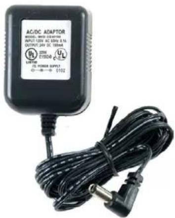
Software CD Power Supply Unit
POSITIONING THE ADAPTERS
2.1 Positioning the DisplayDock
The Wireless USB DisplayDock is designed for two possible mounting options:
- Simple table placement – the Docking Base is placed on a flat horizontal surface, and the Device Adapter is connected at 90 degrees to the base so that it is vertical.

natural_image
Line drawing of a portable electronic device with a top-mounted antenna and control buttons (no text or symbols)- Vertical mounting – the Docking Base is fastened to a wall, a projector, or behind a display screen, and the Device Adapter is connected so that it is flat with the mounting surface, with the Device Adapter pointing upwards.

natural_image
Illustration of a device and a computer monitor with cables (no text or symbols)Note: For best performance, it is recommended to always position the Device Adapter vertically so that it is pointing upwards.
2.2 Positioning the PC Adapter
To achieve best performance it is recommended to position the PC Adapter in the upright position.

natural_image
Line drawing of a laptop computer with blank screen and keyboard (no text or symbols)Figure 1: PC in working mode - PC Adapter in upright position
When the laptop is not in use, the PC Adapter can be rotated 90 degrees for storage, as seen in the following illustration:

natural_image
Line drawing of a rectangular electronic device with a red tag on the side panel (no text or symbols)Figure 2: Laptop inactive - PC adapter in horizontal position for storage.
SOFTWARE INSTALLATION AND FIRST CONNECTION
| 1. Ensure that the PC Adapter is unplugged from the PC. | |
| 2. Insert the installation CD in the PC CDROM drive. | |
| 3. The installation CD Autoplay menu is displayed. |  |
| 4. Select Install Wireless USB Software.The installer offers two options:Option 1: Install Directly from CD - initiates the installation process from the CD.Option 2: Download latest software from the WEB - provides a link to a web address where you can download software updates. If you choose this option, follow the instructions provided on the software download page. |  |
| 5. If you select Option 1: Install Directly from CD, the install wizard begins installing the Wireless USB software. The installation process may include more than one stage to accommodate different drivers that are installed. Following the Wireless USB drivers, the Disp drivers and application are installed. | 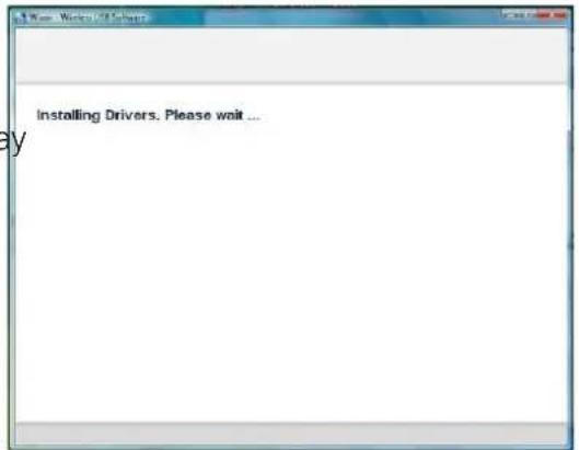 |
- Choose your geographic region to comply with your local radio regulations. This setting can be changed if needed once the software is installed.

- Follow the onscreen instructions, and proceed by clicking Next> when prompted, or by approving authorization requests to continue the installation.
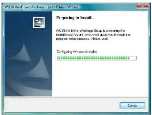
- When the Wireless USB Driver installation has completed, the Display driver installation begins. Click I Accept to approve the end-user license agreement and continue installation.


- When the installation procedure has successfully finished, you are automatically returned to the opening screen of the Autoplay menu. You may be requested to reboot.

3.1 Connect the PC Adapter to the PC
- Connect the Wireless USB PC Adapter to a high speed PC USB port. The system will automatically detect and install the drivers for the connected PC Adapter.
- System Tray icon turns red 📋 to indicate that the PC Adapter (Host) is ready to connect to any paired device in range.
3.2. Connect the DisplayDock
- Attach the DisplayDock to the remote display device (TV/Projector/Monitor), and ensure the PC (with PC Adapter attached) is within 3 meter distance from the DisplayDock for the initial connection. Ensure the two adapters have clear line-of-sight. Connect the provided power supply to the Docking Base power receptacle.
Note: The PC Adapter and Device Adapter in this set are already paired and do not require performing a pairing procedure. If you should need to perform pairing manually for any reason (e.g. connecting to a new host PC Adapter, or adding a Device Adapter that was not purchased in a set), please refer to Appendix B: Pairing Procedure
- Wait for the System Tray icon to turn green 📋, indicating that a wireless connection with the A/V Adapter has been established. The Display icon is also displayed as soon as a connection is established and the Display drivers are active.

Note: If you do not see the icon changing to green, or do not see the Display icon, please see Appendix A: Troubleshooting Help for suggestions.
3.2.1 Connecting Audio
Connect an audio cable with a 3.5mm (mini-stereo) plug to the audio jack on the Docking Base. Connect the other end of the cable to the appropriate audio input jack on the TV/Projector/Monitor. The audio output driver is activated automatically.
Note: If you need to set the audio output device manually Setting Audio Output Device.
3.2.2 Connecting USB Keyboard and Mouse
- Attach the USB Keyboard or Mouse to one of the USB ports of the Docking Base. Wait for the PC to recognize the USB device connection.
- If needed, install the device drivers which were supplied with your Keyboard or Mouse.
- Finally a popup balloon saying the new device is ready to use should appear.
Note: The DisplayDock is designed to work with USB Keyboard and Mouse. Other USB devices may not operate properly when connected to the USB ports of the DisplayDock.
Wireless USB Manager User Interface
The Wireless USB Manager allows you to monitor and control the available Wireless USB devices and connections that are within range of the PC.
4.1 Wireless USB Manager System Tray Icon
The Wireless USB Manager icon is automatically displayed in the Windows System Tray whenever Windows starts. The color and shape of the icon indicates the current activity state, as described in the following table:
| Icon Color Status | |
| Connected (green icon)A wireless connection is established with a Wireless USB Device Adapter. | |
| Host Hardware Enabled (red icon)Wireless USB PC Adapter is connected to the PC (PC Adapter is enabled), but no wireless connection is detected. | |
| Host Hardware Disconnected (gray icon)Wireless USB PC Adapter is not connected. | |
| Host Hardware Disabled (gray icon with X) Wireless USB PC Adapter is disabled.Note: Under the Japan regional setting, this icon is displayed whenever the AC power source is disconnected from the PC. | |
| Wireless USB Channel is Busy (green icon with exclamation)Low channel quality detected, but at least one Wireless USB device is still connected. To improve connection quality, see Appendix A: Troubleshooting Help for suggestions. | |
| Wireless USB Channel is not available (red icon with exclamation) No available channel detected. To improve connection quality, see Appendix A: Troubleshooting Help for suggestions. | |
4.2 Accessing the Wireless USB Manager
To access the Wireless USB Manager:
- Right click the Wireless USB Manager System Tray icon and select Wireless USB Connections to display the Wireless USB Manager screen.

Figure 3: System Tray Icon - Context menu
Table 1: Context menu options
| Menu Option Description | |
| Wireless USB Manager | Displays the main user interface, which displays a list of Wireless USB devices that are available, and their connection status (Connected, Not Connected, Blocked) |
| Help Opens the help/troubleshooting file (HTML format) in a browser | |
| About Displays the About screen, containing version information for the drivers and software. | |
| Exit Closes the Wireless USB Manager application | |
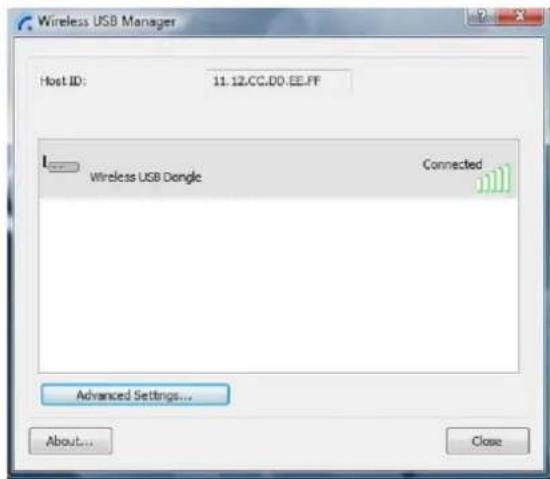
Figure 4: Wireless USB Manager– remote device connected
Table 2: Wireless USB Manager options
| Menu Option Description | |
| Host ID Displays the | currently connected PC Adapter ID number |
| Connection Quality | The following are the different states of the connection status icon which indicates the connection quality:Blocked -Not connected -Connected -Medium -  Good -Very Good -Excellent - Good -Very Good -Excellent - |
| Advanced Settings | Displays the Advanced Settings screen, allows configuration of the PC Adapter RF settings. |
| Close Closes the Wireless USB Manager screen, does NOT close the Wireless USB Manager application. | |
| About Displays the A | about screen containing basic information regarding the software version and vendor details |
| (Help) | Opens the help/troubleshooting file (HTML format) in a browser |
4.3 Blocking or Disassociating a Device
The Wireless USB Manager screen allows you to remove devices or to temporarily disable them from connecting to the Host. To Block a device temporarily, and prevent it from connecting to the Host:
- Right click the device name in the Connection list and select Block Device.
Block device Disassociate Device Properties ...
Figure 5: Wireless USB Manager Context Menu
To remove a device from the list of available devices completely:
- Right click the device name in the Connection list and select Disassociate Device
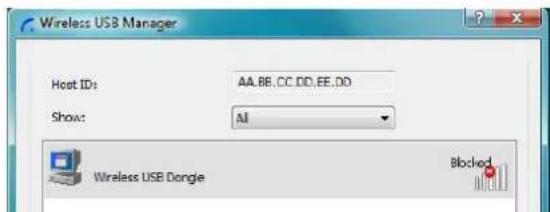
Figure 6: Wireless USB Manager– remote device blocked
Note: The Disassociate Device option is only available for Device Adapters that are purchased separately and not in a set. For information about pairing an Adapter set, see Appendix B: Pairing Procedure.
Table 3: Context menu options
| Menu Option Description | |
| Block/UnBlock Device | Allows you to temporarily disable a device from connecting with the Host. |
| Disassociate Device | Removes the device from the list. To return the device to the list, Pairing must be performed again. |
| Properties Displays the properties screen for this device. | |
4.4. Changing Device Names in the Wireless USB Manager
The Wireless USB Manager screen allows you to modify the name of the device that appears in the connections list.
To modify the device name:
-
Double-click the device name, or right click on the device name and choose Rename.
-
Enter the text that you want.
-
Click anywhere outside of the device name area to finalize.
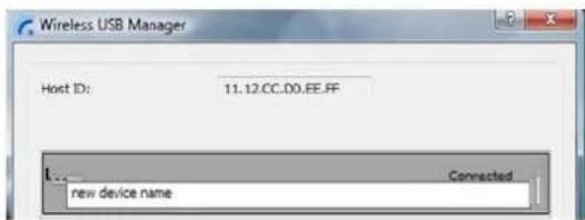
Figure 7: Editing Device Name in Wireless USB Manager
4.5. Advanced Settings
The Advanced Settings screen of the Wireless USB Manager allows viewing advanced settings, and allows configuration of the Channel and Region selection in the Host. To access the Advanced Settings screen:
• In the Wireless USB Manager screen, click Advanced Settings

Figure 8: Advanced Settings Screen
| Option Description | |
| Region Allows selecting the regulatory region: USA, Europe, Japan, Korea, China | |
| Current Channel (read only) | Displays the current PHY Channel |
| Channel Quality (read only) | Displays Channel quality: Excellent, Very Good, Good, Low, Not Connected |
| Select Channel Allows selecting PHY Channels: 13*, 14, 15# | |
| Select Rate (Mbps) This option is not active. | |
| OK Applies configuration changes that were made | |
| Close Closes the Advanced Settings screen | |
Notes: * This is the default value for USA region.
This is the only available option for Europe, Japan, Korea and China regions.
USING AND CONFIGURING THE DISPLAYDOCK
5.1 Using the DisplayDock Video connection
The following are suggested work modes for connecting a display screen to the DisplayDock:
- Mirror Mode
- Extend Mode
- Laptop with Lid Closed
- External Display Only
Note:
On Windows XP/Vista, the display properties for the DisplayDock can be configured in two ways: as described in Sec. 5.3.1 Configuring the Display via the Display Icon Context Menu in Windows XP/Vista, or as described in Sec. 5.3.2 Configuring the Display via Windows Display Properties in Windows XP/Vista.
On Windows 7, refer to Sec. 5.2 Configuring Display in Windows 7
When changing settings, or during first connection between the PC Adapter and DisplayDock, the PC display may flicker or turn on and off as the screen resolution is automatically adjusted.
Upon first time operation, the DisplayDock is in Extend mode, this section (Sec. 5.1) describes the different modes that can be set. In Sec. 5.2 and 5.3.2 you will find the procedures for configuring these modes.
5.1.1 Using Mirror Mode
Mirror mode is used to display the identical content on the additional screen as is shown on the main PC/Laptop screen. Mirror mode is generally used to display the PC contents on a larger or higher definition display. See Figure 9: Mirror Mode - displaying PC desktop on a larger display screen.

flowchart
graph TD
    A["Speakers"] --> B["MONITOR"]
    C["KEYBOARD"] --> B
    D["MOUSE"] --> B
    B --> E["Device Adapter"]
    E --> F["PC Adapter"]
    style A fill:#f9f,stroke:#333
    style C fill:#f9f,stroke:#333
    style D fill:#f9f,stroke:#333
    style E fill:#ccf,stroke:#333
    style F fill:#ccf,stroke:#333
Figure 9: Mirror Mode - displaying PC desktop on a larger display screen
Note: Mirror mode is not recommended for playing HD video.
5.1.2 Using Extend Mode
Use the Extend mode to display different content on each display screen. In Extend mode, the display attached to the DisplayDock becomes an extended part of the Windows desktop. The extra desktop area is a great productivity aid, allowing you to view or work with more applications or documents at the same time. You can also use this mode to extend your desktop to fill multiple screens that are positioned next to each other for a larger continuous work space.

Figure 10: Illustration of extend mode Note: Extend mode is recommended for playing HD video.

flowchart
graph TD
    A["Speaker"] --> B["MONITOR"]
    C["Keyboard"] --> B
    D["Speaker"] --> E["DEVICE ADAPTER"]
    F["Mouse"] --> E
    B --> E
    E --> G["PC ADAPTER"]
Figure 11: Extend Mode - using second display for an additional application or a movie
5.1.3 Laptop Operation with the Lid Closed
You can work conveniently with a laptop by setting its default action upon closing the lid to "Do nothing" (to prevent the laptop from entering "sleep" or "hibernation" mode, Control Panel > Power Options, "When I close the lid:" - "Do nothing"), and then set the DisplayDock screen as the primary display while disabling the main screen (see Sec. 5.3.2.5 Setting the DisplayDock as the Primary Display).
The laptop lid can then be closed, and the laptop can be used with the DisplayDock screen and an external keyboard and mouse attached to the laptop. This configuration can be used together with either Mirror mode or Extend mode.
5.1.4. External Display Only
When you want to use the external display only, (see Sec. 5.3.2.5 Setting the DisplayDock as the Primary Display), you can close your main monitor and view movies on the external display attached to the DisplayDock.
5.2. Configuring Display in Windows 7
5.2.1 Setting Mirror or Extend Mode in Windows 7
In Windows 7, there is a built-in support for external monitor. To use it press the windows key together with the P key (4P), and then the following menu will appear:

Figure 12 - Switching projection mode under Windows 7
- For mirror mode, choose Duplicate
- For Extend mode, choose Extend
5.2.2 Configure Screen Options in Windows 7
When a link is established with the Wireless USB DisplayDock, the Display drivers are activated and the Display icon appears in the Windows system tray. The right-click context menu of the Display icon contains configuration options that correspond to the display mode.

Figure 13 - DisplayLink Context Menu
To configure screen resolution, or any other display option, choose Advanced. The following window will appear:
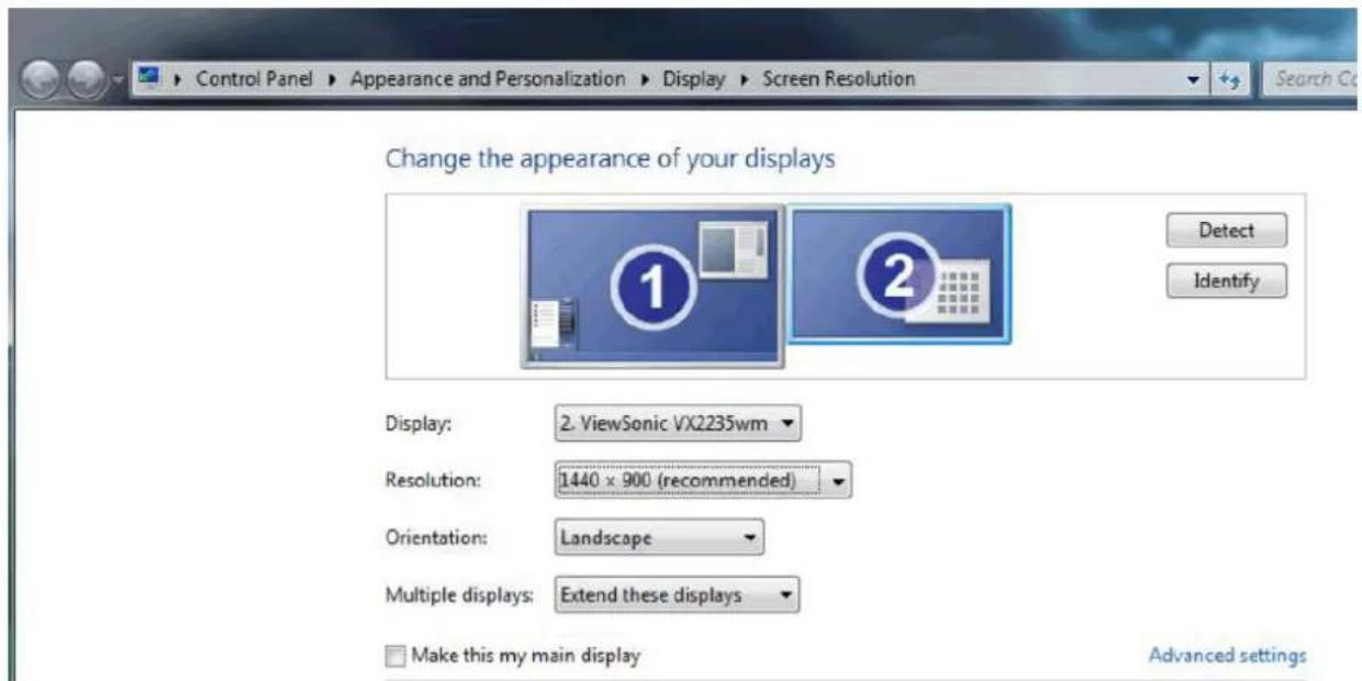
Figure 14 - Windows 7 Display Settings
To change any of the external display settings:
- Select the appropriate display name in the Display scroll down options. You should select the name of the TV/Monitor/Projector connected to your DisplayDock.
- Select the desired value in any of the available settings:
a. Resolution: your external display resolution.
b. Orientation: select either Landscape or Portrait.
c. Multiple displays: select either Mirror or Extend mode.
d. Make this my main display: mark this option to make the external display the primary display on which the desktop is displayed.
5.3 Configuring Display in Windows XP/Vista
5.3.1 Configuring the Display via the Display Icon Context Menu in Windows XP/Vista
When a link is established with the Wireless USB DisplayDock, the Display drivers are
activated and the Display icon – appears in the Windows system tray. The right-click context menu of the Display icon contains configuration options that correspond to the display mode.
Note: When changing settings, the PC display may flicker or turn on and off as the screen resolution is automatically adjusted.
| Configuration Option Options available | able Remarks | ||
| Screen Resolution Extend mode only | |||
| Color Quality | Extend mode only | ||
| Screen Rotation | |||
| Extend To | |||
| ● Extend | |||
| Mirror | |||
| Off | |||
| Extend To Extend mode only | |||
| Extend | Sets the Extend mode | ||
| Mirror Sets the Mirror mode | |||
| Off Disables the remote display Select | Mirror or Extend mode to enable the display | ||
| Advanced Opens the Windows Display Settings screen | |||
5.3.1.1 Setting Mirror Mode
To set the display to Mirror mode:
- Right click the DisplayLink System Tray icon and select Mirror from the context menu

- The resolution, color depth and refresh rate of the primary screen are duplicated on the display connected to the DisplayDock.
- If the display connected to the DisplayDock supports a lower resolution than the primary display, the primary graphics device will have its resolution changed automatically to ensure the whole picture fits on the additional display screen.
- If the display screen connected to the DisplayDock is larger than the primary screen, the image will be adjusted to a letter-box frame to preserve the correct aspect ratio.
Note: When changing from Extend to Mirror mode, it is recommended to first set the Display to Off, and then set to Mirror.
5.3.1.2 Setting Extend Mode
To set the display to Extend mode:
- Right click the DisplayLink System Tray icon and select Extend from the context menu. You can also select the Extend To option to specify which side of the extended space is occupied by the extended display.


Note: When changing from Mirror to Extend mode, it is recommended to first set the Display to Off, and then set to Extend.
To place an application window in the extended space, use the following tips:
- Reduce the application window size to about half the normal size, and then drag the application window (dragging by the Title Bar at the top of the screen) past the edge of your main display and into the extended display space. Resize the window in the extended space as needed for comfortable viewing.
- When dragging a running process window such as a movie or other application from the main screen to the extended screen, it is recommended to pause or stop the running application first, and restart it in the extended screen.
5.3.2 Configuring the Display via Windows Display Properties in Windows XP/Vista
Display settings can also be configured from the Windows Display Properties dialog box. (In Windows Vista: right click on the desktop, select Personalize > Display Settings. InWindows XP: right click on the desktop, select Properties>Settings tab).
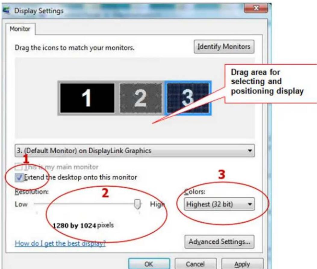
Figure 14: Windows Display Settings
5.3.2.1 Selecting the Correct Display Monitor
In the monitor drop down box, find the entry for the DisplayDock display monitor “... on DisplayLink Graphics”. You can arrange this display's position with respect to the other monitors on the extended desktop by using the drag area at the top of the Windows Display Settings dialog. If you are not sure which number represents which display, click Identify Monitors and a large identifying number will appear on each display.
5.3.2.2 Setting the Display to Extend or Mirror Mode
To set the display in Extend mode, check the option Extend the desktop onto this monitor To set the display into Mirror mode, uncheck the box marked Extend the desktop onto this monitor (see circle #1 in Figure 14).
5.3.2.3 Adjusting Screen Resolution
Use the Resolution slider to adjust the desired resolution of the display (see circle #2 in Figure 14).
5.3.2.4 Adjusting Color Level
Use the Colors drop-down box to select a color complexity level (see circle #2 in Figure 14).
5.3.2.5 Setting the DisplayDock as the Primary Display

To make the DisplayDock display the primary display:
-
Select the screen that is connected to the DisplayDock - for example "Default Monitor on DisplayLink Graphics Adapter" as shown in the screen above.
-
Check the option Extend the desktop onto this monitor. (In Windows XP - Extend my Windows desktop onto this monitor).
-
Check the option This is my main monitor. (in Windows XP - Use this device as the primary monitor).
-
Click OK to save the new settings. Note: On some PCs it is necessary to disable the main display (uncheck the box marked 'Extend the desktop onto this monitor' for the main display) as part of the same settings change. The DisplayDock remains the primary one if the PC enters Hibernate or Suspend mode or is rebooted. If the DisplayDock is detached, the main display becomes the primary display again.
5.4 Optimizing Wireless Video Display
The following are suggested operating modes for best results in displaying video with the Wireless USB DisplayDock. Additional suggestions can be found in Appendix A: Troubleshooting Help.
5.4.1 Use Extend Mode
For optimum performance it is recommended to use Extend mode. When playing HD movies it is recommended to limit the extended screen to 720p resolution (i.e. 1280x720) or any closer resolution.
5.4.2 Optimizing Internet Video Viewing
Many video content websites use an embedded Adobe Flash player to show video content. In some cases to achieve best performance with the Flash player, (for example, when viewing online video content in full screen mode) adjust the Flash Player settings as follows.
To optimize the Flash player for the DisplayDock:
- Right click the video content on the website and select Settings from the Adobe Flash Player context menu.

- In the Adobe Flash Player Settings screen, uncheck the Enable hardware acceleration option and click Close to close the settings screen.

- Resume viewing the video content.
5.4.3 Using Optimize for Video Mode
For best performance when using the Wireless DisplayDock, use the Optimize for Video mode (if available).

5.4.4 Setting Aero Desktop Theme in Vista
For best performance when using the Wireless DisplayDock with Windows Vista operating platform, it is recommended to use the Aero desktop theme.
To set the Vista desktop to the Aero theme:
- Right click the desktop and select Personalize.
| ATI CATALYST(R) Control Center | |
| View | |
| Sort By | |
| Refresh | |
| Paste | |
| Paste Shortcut | |
| Undo Copy Ctrl+Z | |
| New | |
| Personalize | |
- In the Control Panel > Personalization screen, select Windows Color and Appearance
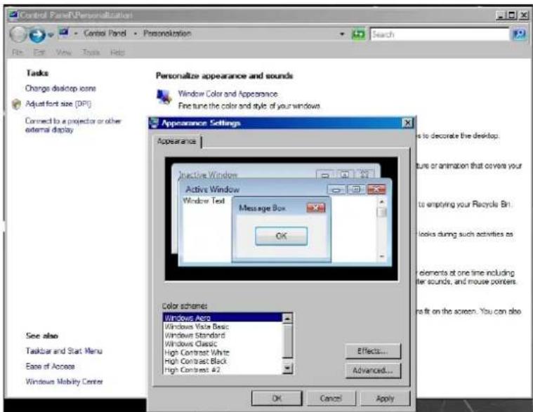
- Select Windows Aero from the Color scheme list, click OK to save the new setting.
5.4.5 Recommended Media Player Applications
On Vista WDDM Aero and Windows XP (in Extend mode), the DisplayDock can display media files and DVDs using the following media players:
• Windows Media Player 11 (http://www.microsoft.com/windows/windowsmedia/default.mspx)
• WinDVD 8 (www.intervideo.com)
• PowerDVD 7 (www.cyberlink.com)
• RealPlayer 11 (www.real.com)
Note: To get a better idea of what you can do with the DisplayDock and multiple display screens, please see the web page "How it Works" at this address: http://www.displaylink.com/how_it_works.html
5.4.6 Recommended Minimum System Requirements
For best performance, the following are the recommended minimum system requirements:
• Personal computer with USB 2.0 port available
- Microsoft Windows® XP SP3, or Microsoft Windows Vista SP2 (32 or 64 bit)
• TV/display/projector with DVI port
- When using Windows XP:
- For office use, productivity, web browsing etc.: At least 1.6GHz Atom or Celeron processor and 512MB memory
- For full screen video, 720p playback etc.: At least 1.8GHz Core2 Duo processor and 1GB memory
- When using Windows Vista:
- For office use, productivity, web browsing etc.: At least 1.6GHz Core Solo processor and 1GB memory
- For full screen video, 720p playback etc.: At least 1.8GHz Core2 Duo processor and 1GB memory
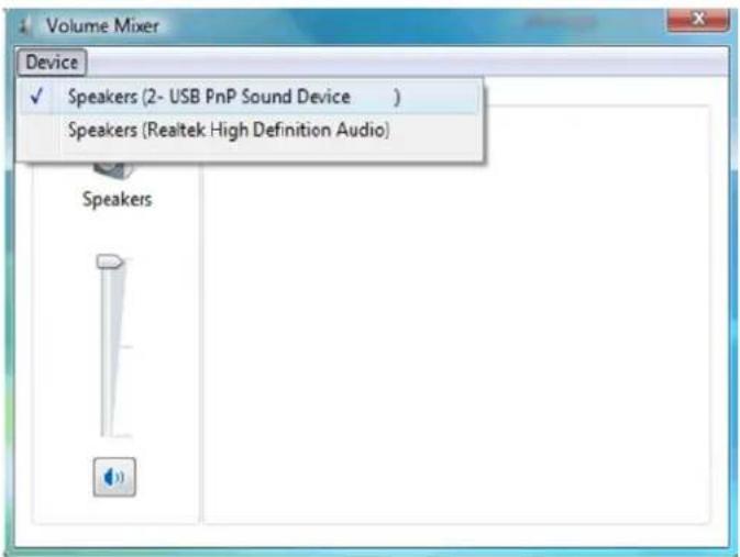
5.5 Setting Audio Output Device
The PC audio output device should set itself automatically to the connected DisplayDock CMedia audio device. If it doesn't, you can select the correct Audio Playback device from the drop down dialog as follows:
In Windows XP:
- Right click the Volume icon in the System Tray and select Adjust Volume Properties.
- In the Sounds and Audio Devices Properties screen, select the Audio tab.
- In the Sound Playback > Default Device drop-down box, select the USB PnP Sound Device.
- Click OK to save the new setting.

In Windows Vista:
- Right click the Volume icon in the System Tray and select Open Volume Mixer.
- In the Volume Mixer screen, click Device and select the USB PnP Sound Device from the drop down list.
- Close the Volume Mixer screen to save the new setting.
In Windows 7:
-
Right click the Volume icon in the System Tray and select Open Volume Mixer.
-
In the Volume Mixer screen, under Device, click Speakers and select the USB PnP Sound Device from the drop down list.
-
Close the Volume Mixer screen to save the new setting.

LED Indications
The following LED indications allow you to see the operational status of the Wireless USB adapters.
- Power:
- OFF when no power is applied or adapter is not connected
- Momentary green when initially connected to USB port.
- Traffic - Rapid flashing when data is received.

Figure 15: Wireless USB Adapter LED
APPENDIX A: TROUBLESHOOTING HELP
| Problem/Question Symptoms Solution | ||
| PC Adapter is attached to PC, but I see the Gray icon in System Tray. | Host show Disconnected (Gray) icon  in System Tray in System Tray | Detach and re-attach PC AdapterORExit from the Wireless USB Manager (right-click the System Tray icon, select Exit) and restart the Wireless USB Manager.ORDetach PC Adapter, restart PC, re-attach the PC Adapter |
| Display Adapter icon is not displayed in the System Tray | Display Adapter icon  is not displayed in the System Tray. is not displayed in the System Tray. | Detach and re-attach the power supply of the A/V Adapter ORDetach and re-attach the PC Adapter to restart the adapter hardware.ORReset the PC and try again to establish the wireless connection to the A/V Adapter. |
| The External Display is not activated | No image is displayed by the remote screen (external display). | Check to see that the video cable between the DisplayDock and the display screen is connected properly and securely.Ensure that you have selected the correct input source in the display screen controls (e.g. HDMI, VGA, Line In, and Digital Input).Check to see that the power supply to the display screen is connected properly.Make sure that the Screen Resolution that is set on the PC is supported by the external display. Please see Sec. 5.2Configuring Display in Windows 7 or Sec. 5.3 Configuring Display in Windows XP/Vista. You can also try switching between the different screens resolutions until picture appears on the TV. |
| The DisplayDock is not activated | No image is displayed by the remote screen, and the DisplayDock LED is off. | Make sure you have connected the power supply to the correct port on the Docking Base. |
| Problem/Question Symptoms Solution | ||
| Movie playing is disrupted by moving the laptop | Some laptop models offer an active hard-disk protection feature that locks the hard-disk when too much motion is detected by the laptop. This may cause movie playing to be disrupted when moving or jarring the laptop. | Disable or lower the sensitivity of the active hard-disk protection mechanism. |
| Movie playing performance is poor | Movie playing is jumpy or uneven or may get stuck due to weak wireless connection. | Open the Wireless USB Manager and check the Connection Quality indication - adjust the distance and/or the line of sight between the PC and the DisplayDock to improve the wireless connection quality. |
| Online movies freeze in full screen mode | Movie freeze when going to full screen mode on websites which use an embedded Adobe Flash player. | In the Adobe Flash Player Settings screen, un-check the Enable hardware acceleration option. Please see Sec.Error! Reference source not found.Error! Reference source not found. |
| Video does not play properly on Apple's QuickTime player | When using QuickTime player, the video looks green/pink or does not play on the remote display. | Open QuickTime: Click Start > Program Files > QuickTime. On the QuickTime application click Edit > Preferences > QuickTime Preferences, and then switch to Safe Mode under the Video setting. |
| TV by default is setup to a specific resolution, and is not scanning the HDMI for supported resolutions | When connecting a TV in HDMI mode the picture on the TV is too big (only part of my laptop screen is showing)ORWhen connecting a TV in HDMI mode the picture on the TV is too small (Black bars are seen around the picture) | In the TV setup screen look for a method for either:Enabling the HDMI scanSwitch to PC modeDisable Over ScanIf neither of these modes is available, please try to select different screen resolutions in the TV until you find one that fits the resolution you have selected on your laptop screen settings. |
| For more Display Adapter tips and information: | Please refer to the Support Knowl-edgebase section of the DisplayLink website for more specific information and answers to questions:www.displaylink.com/support/knowledgebase.phpFor basic definitions, see the Frequently Asked Questions:www.displaylink.com/setup_faqs.html. | |
| Audio is not synchronized with the video | When you play a video, the audio part of the playback may not be synchronized with the video playback. | Change the active power plan to 'Always On' or to 'Balanced' or to 'High Performance'.XP: Click Start, select Control Panel. Click Power Options.Under Power Schemes select Always On.Vista: Click Start, type power in the Start Search box, and then click Power Options in the Programs list.Under Select a power plan, click Balanced or click High performance. |
| No Audio on the remote speakers connected to the DisplayDock | When you play a video and the audio part of the playback is heard from the PC speakers and not from the remote speakers. | Make sure you have connected the remote speakers to the 3.5mm audio port.On the media player press Stop and then Play to restart the video. Please see Sec. 5.5 Setting Audio Output Device for further details. |
| Problems in establishing connection with Device (red) iconin System Tray | To check if a device is connected, right click the System Tray icon and select Wireless USB Manager to view the list of available devices and to see the green Connected icon next to the device name of the newly established connection - Green System Tray icon - Green System Tray icon  not light up to indicate that a connection has been established,OR- The Device is not listed in the Wireless USB Manager screen not light up to indicate that a connection has been established,OR- The Device is not listed in the Wireless USB Manager screen | Power not connected to Device: ensure that the correct power supply is connected to the device side.Device Adapter requires restart: detach and re-attach the Device Adapter from the Table Adapter to restart the hardware.Wireless Device is out of range: if you experience frequent Wireless link disconnection, the Wireless Device may be out of range –the solution is to bring the Wireless Device closer to the Wireless USB Host.Device Adapter requires pairing: if you are adding a Device Adapter that was not part of a set, or if you are connecting to a new unrecognized Host, you may need to perform the Pairing procedure see Appendix B: Pairing Procedure |
| Problem/Question Symptoms Solution | ||
| Channel busy message displays when I try to change the channel Note: manual channel selection may be restricted by local communication regulation laws. | External radio interference may exist close to the PC/device Channel selection SW may have failed | Another wireless system may be in use in proximity to the PC or device environment, and may cause temporary interference to the wireless USB system. Try to select a different channel (where applicable - local regulatory restrictions may apply) Close the message box, detach the PC Adapter from your PC and re-attach it. If the message displays again, try to change the channel again. |
| Problems with Pairing see also - Appendix B: Pairing Procedure | The Pairing procedure does not result in the confirmation screen "WIRELESS USB device has been paired", or results in an error message.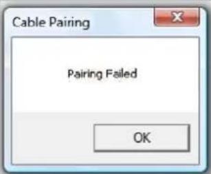 | Detach and re-attach Device Adapter OR Re-attach PC Adapter, then attach Device Adapter OR Detach all Adapters, restart PC and tryPairing again |
| Pairing with multiple Hosts present – each pairing must correspond to a specific PC Adapter (Host) see also - Appendix B:Pairing Procedure | If more than a single PC Adapter (Host) has been attached to the PC at any time, the pairing process requires that at least one PC Adapter be connected while the Device Adapter is being paired | Ensure that a single PC Adapter is attached to the PC, and then re-attach the Device Adapter to perform Pairing |
APPENDIX B: PAIRING PROCEDURE
The PC Adapter and Device Adapter in this set are already paired and do not require performing a pairing procedure. If you should need to perform pairing manually for any reason (e.g. connecting to a new host PC Adapter, or adding a Device Adapter that was not purchased in a set), please follow these steps: To perform Pairing:
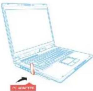
- Ensure that a Wireless USB Host or PC Adapter is connected to the PC.
natural_image
Line drawing of a laptop with a pointing hand, no text or symbols present- Remove the Device Adapter from the Docking Base and connect it directly to the host PC USB port, do not use the Docking Base or any other accessory to connect to the PC.

-
Upon first time connection of a Device Adapter to the PC, the Pairing driver is installed automatically.
-
Once the Pairing driver is installed, pairing is automatically performed between the host PC and the Device Adapter, and the following confirmation message is displayed:
| Windows VISTA Windows XP | |
 | 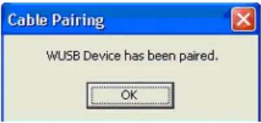 |
- Click OK to confirm and close the Cable Pairing screen.
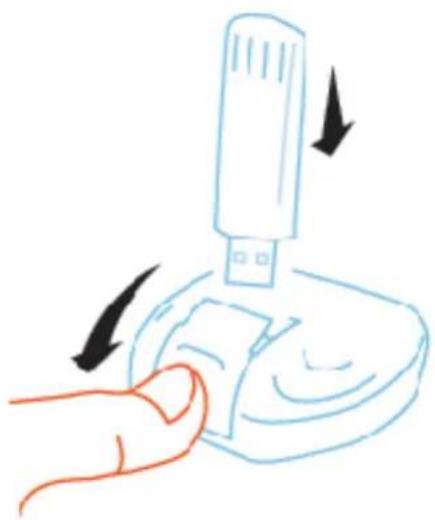
- Remove the Device Adapter from the PC and reconnect it to the Docking Base.

natural_image
Hand inserting a small object into a device with arrows indicating process (no text or symbols)SAFETY INFORMATION
Safeguards

To reduce the risk of electric shock, do not expose this product to rain or moisture

If the wall plug does not fit into your local power socket, hire an electrician to replace your obsolete socket.

Do not modify the wall plug. Doing so will void the warranty and safety features.

This equipment should be installed near the socket outlet and the device should be easily accessible in the case it requires disconnection.
Precautions
FCC regulations state that any unauthorized changes or modifications to this equipment, not expressly approved by the manufacturer, could void the user's authority to operate this equipment.
Operate this product using only the included external power supply. Use of other power supplies could impair performance, damage the product, or cause fires.
In the event of an electrostatic discharge this device may automatically turn off. If this occurs, unplug the device and plug it back in.
Protect and route power cords so they will not be stepped on or pinched by anything placed on or against them. Be especially careful of plug-ins or cord exit points from this product.
Avoid excessive humidity, sudden temperature changes or temperature extremes.
Keep this product away from wet locations such as bathtubs, sinks, laundries, wet basements, fish tanks, and swimming pools.
Use only accessories recommended by Atlona to avoid fire, shock, or other hazards.
Unplug the product before cleaning. Use a damp cloth for cleaning and not cleaning fluid or aerosols. Such products could enter the unit and cause damage, fire, or electric shock. Some substances may also mar the finish of the product.
Never open, remove unit panels, or make any adjustments not described in this manual. Attempting to do so could expose you to dangerous electrical shock or other hazards. It may also cause damage to your AT-PCLINK. Opening the product will void the warranty.
Do not attempt to service the unit. Disconnect the product and contact your authorized Atlona reseller or contact Atlona directly.
WARRANTY
Limited Warranty
Atlona Technologies warrants that (a) its products (the AT-PCLINK) will perform substantially in accordance with the accompanying written materials for a period of 3 years from the date of receipt and (b) that the product will be free from defects in materials and workmanship under normal use and service for a period of 3 years. In the event applicable law imposes any implied warranties, the implied warranty period is limited to 3 years from the date of receipt. Some jurisdictions do not allow such limitations on duration of an implied warranty, so the above limitation may not apply to customers that fall within those areas.
Customer Remedies
Atlona Technologies' and its suppliers' entire liability and Customer's exclusive remedy shall be, at Atlona Technologies' decision, either return of the price paid for the product, repair, or replacement of the product that does not meet this Limited Warranty and which is returned to Atlona Technologies with a copy of the Customer's receipt. This Limited Warranty is void if failure of the product has resulted from accident, abuse, misapplication, or natural occurrence. In example but not limited to: power surges (electrical storms, local power outage), dropping the product (or items on the product), contact with fluids, and physical misconduct (i.e. kicking or punching). Any replacement product will be warranted for the remainder of the original warranty period.
No other warranties
To the maximum extent permitted by applicable law, Atlona Technologies and its suppliers disclaim all other warranties, either expressed or implied, including, but not limited to, implied warranties of merchantability and fitness for a particular purpose, with regard to the product and any related written materials. This Limited Warranty gives customer specific legal rights. Customers may have other rights depending on the jurisdiction.
No liability for damages
To the maximum extent permitted by applicable law, in no event shall Atlona Technologies or its suppliers be liable for any damages arising out of the use of or inability to use this product, even if Atlona Technologies has been advised of the possibility of such damages. Such damages include but are not limited to: special, incidental, consequential, or indirect damages for personal injury, loss of business profits, business interruption, loss of business information, or any other pecuniary loss. Atlona Technologies' and its suppliers' entire liability under any provision of this agreement shall be limited to the amount actually paid by you for the product. Some Jurisdictions do not allow the exclusion or limitation of liability for consequential or incidental damage. The above limitations may not apply to you in such jurisdictional cases.
ATLONA PRODUCT REGISTRATION
Thank you for purchasing this Atlona product. - We hope you enjoy it and will take an extra few moments to register your new purchase.
Registration creates an ownership record if your product is lost or stolen and helps ensure you'll receive notification of performance issues and firmware updates.
At Atlona, we respect and protect your privacy, assuring you that your registration information is completely secure. Atlona product registration is completely voluntary and failure to register will not diminish your limited warranty rights.
To register go to: http://www.atlona.com/registration
- TABLE OF CONTENTS
- What's in the Package
- POSITIONING THE ADAPTERS
- Positioning the DisplayDock
- Positioning the PC Adapter
- Connect the PC Adapter to the PC
- Connect the DisplayDock
- Connecting Audio
- Connecting USB Keyboard and Mouse
- Wireless USB Manager User Interface
- Wireless USB Manager System Tray Icon
- Accessing the Wireless USB Manager
- Blocking or Disassociating a Device
- Changing Device Names in the Wireless USB Manager
- Advanced Settings
- This is the only available option for Europe, Japan, Korea and China regions.
- USING AND CONFIGURING THE DISPLAYDOCK
- Using the DisplayDock Video connection
- Note:
- Using Mirror Mode
- Using Extend Mode
- Laptop Operation with the Lid Closed
- External Display Only
- Configuring Display in Windows 7
- Setting Mirror or Extend Mode in Windows 7
- Configure Screen Options in Windows 7
- To change any of the external display settings:
- Configuring Display in Windows XP/Vista
- Configuring the Display via the Display Icon Context Menu in Windows XP/Vista
- Setting Mirror Mode
- Setting Extend Mode
- Configuring the Display via Windows Display Properties in Windows XP/Vista
- Selecting the Correct Display Monitor
- Setting the Display to Extend or Mirror Mode
- Adjusting Screen Resolution
- Adjusting Color Level
- Setting the DisplayDock as the Primary Display
- Optimizing Wireless Video Display
- Use Extend Mode
- Optimizing Internet Video Viewing
- To optimize the Flash player for the DisplayDock:
- Using Optimize for Video Mode
- Setting Aero Desktop Theme in Vista
- To set the Vista desktop to the Aero theme:
- Recommended Media Player Applications
- Recommended Minimum System Requirements
- Setting Audio Output Device
- In Windows XP:
- In Windows Vista:
- In Windows 7:
- LED Indications
- APPENDIX B: PAIRING PROCEDURE
- SAFETY INFORMATION
- Safeguards
- Precautions
- WARRANTY
- Limited Warranty
- Customer Remedies
- No other warranties
- No liability for damages
- ATLONA PRODUCT REGISTRATION
Brand : Atlona
Model : AT-PCLINK
Category : Computer accessory