
6530 - Wall mount MONOPRICE - Free user manual and instructions
Find the device manual for free 6530 MONOPRICE in PDF.


| Product Type | Wall Mount for TVs |
| Brand | Monoprice |
| Model | 6530 |
| Maximum TV Size | 65 inches |
| Maximum Weight Capacity | 130 lbs (59 kg) |
| VESA Compatibility | 100x100mm to 600x400mm |
| Tilt Range | +5° / -15° |
| Swivel Range | ±45° |
| Rotation | ±3° for leveling |
| Material | Cold rolled steel, powder coated |
| Distance from Wall | 1.5 to 19 inches (3.8 to 48 cm) |
| Installation Type | Fixed to wall studs, included hardware |
| TV Compatibility | Flat or curved screens |
| Wall Plate Dimensions | 32 x 7 inches (81 x 18 cm) |
| Weight of Mount | 8.5 lbs (3.9 kg) |
| Color | Black |
| Included Components | Mount, hardware kit, bubble level, manual |
| Warranty | Limited lifetime warranty |
Frequently Asked Questions - 6530 MONOPRICE
User questions about 6530 MONOPRICE
0 question about this device. Answer the ones you know or ask your own.
Ask a new question about this device
Download the instructions for your Wall mount in PDF format for free! Find your manual 6530 - MONOPRICE and take your electronic device back in hand. On this page are published all the documents necessary for the use of your device. 6530 by MONOPRICE.
USER MANUAL 6530 MONOPRICE
Max Load Capacity: 80 lbs (36kg)

natural_image
Technical line drawing of a vertical mechanical assembly with mounting flanges and mounting brackets (no text or symbols)Note: Read entire instruction sheet before you start installation and assembly.
WARNING
- Be sure to read this entire manual thoroughly and you fully understand all the instructions and warning before attempting to begin your installation.
- This product should only be installed by someone who has a basic knowledge of building construction, in stallations and fully understands these instructions.
- Make sure that the supporting surface will safely support the combined load of the mount, the display and all attached hardware and components.
- This wall bracket will only support flat panel displays(LCD,Plasma).The maximum load capacity is 80 pounds.
- If mounting to a wall of wood stud construction, be sure that mounting bolts are anchored to the center of the studs.
• Always have someone assist you to lift and position your equipment. - Tighten screws and bolts firmly, but do not over tighten. Over tightening can damage the items and greatly reduce their ability to hold. Please refer to suggested torque values where applicable in these instructions.
Tools Needed for Assembly
- stud finder ("edge to edge" stud finder is recommended)
- phillips screwdriver
- drill with 1/4", 3/8", and 5/32" drill bits
Table of Contents
Parts List .... 3
Installation to Wood Joist Ceiling 4
Installation to Concrete Ceiling 5
Installation of Extension Column 6
Attaching display mounting plate to a screen with a VESA ^® Mounting Pattern....7
Tilt Adjustment and Wire Management 8
| Before you begin, make sure all parts shown are included with your product.Parts may appear slightly different than illustrated.Parts ListDescription | ||||
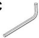
| C | allen wrench | 1 | M2 | |
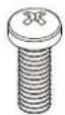
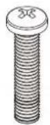
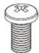
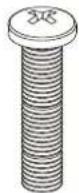
| D | philips pan head screw | 8 | M4x10 | |
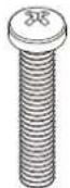
| E | philips pan head screw | 8 | M4x20 | |
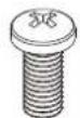
| F | philips pan head screw | 8 | M5x15 | |
| G | philips pan head screw | 8 | M5x30 | |
| H | philips pan head screw | 8 | M6x12 | |
| I | philips pan head screw | 8 | M6x30 | |
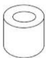
| J | spacer | 8 | ∅12.7x∅6.0x12.7 | |
| K | concrete anchor | 4 | M8x50 | |
| L | washer | 4 | ∅8.2x∅16x1.5 | |
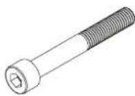
| L | hex bolt screw | 4 | M8x50 | |
| M | Hexagon fillister head screw | 2 | M4x3 | |
| N | nonskid nut | 4 | M8 | |
| N | Hexagon fillister head screw | 4 | M8x60 | |
C
D
E
F
G
H
|
J
K
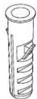
L
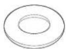
L
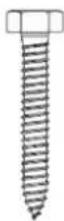
M
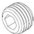
N
N
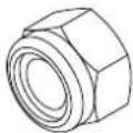
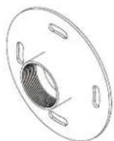
plate (x1)
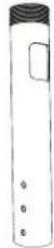
AA (x1) BB (x1)

Installation to Wood Joist Finished Ceilings, Exposed Wood Joists, or Wood Beam Ceilings

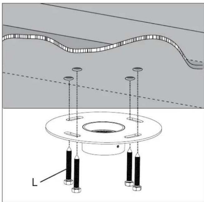
Drill four 1/4" (6 mm) dia. holes to a minimum depth of 1.57" (40 mm). Attach ceiling plate with four hex bolt screws M8x50 (L) as shown using 1/2" (13mm) socket wrench. Tighten wood screws (L). so ceiling plate is firmly attached.
WARNING
- Tighten wood screws so that ceiling plate is firmly attached, but do not overtighten. Overtightening can damage the screws, greatly reducing their holding power.
- Make sure that mounting screws are anchored into the center of the joist. The use of an "edge to edge" stud finder is highly recommended.
natural_image
Technical diagram showing a mechanical assembly with a central circular component and multiple vertical supports, no text or symbols present.Installation to Concrete Ceilings

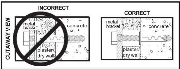
Drill four 3/8" (10 mm) dia. holes to a minimum depth of 1.57" (40 mm). Attach ceiling plate using four concrete anchors (K) and M8x50 hex bolt screws (L) as shown in Illustration A and 1, 2, and 3 (below). Tighten all fasteners.
WARNING
- Tighten wood screws firmly, but do not overtighten.
- Overtightening can damage the bolt, greatly reducing its holding power.
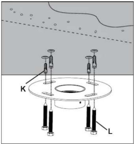
Illustration A
WARNING
- Concrete anchors are not intended for attachment to concrete wall covered with a layer of plaster, drywall, or other finishing material. If mounting to concrete wall covered with plaster/drywall is unavoidable, plaster/drywall (up to 5/8" thick) must be counterbored as shown below. If plaster/drywall is thicker than 5/8", custom fasteners must be supplied by installer.
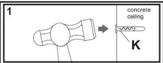
Drill hole and insert anchor
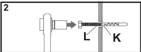
Place ceiling plate over anchor and secure with screw
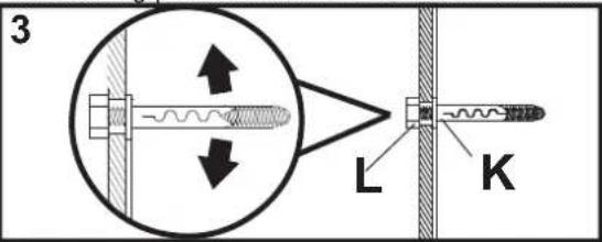
After repeating step one tighten all fasteners
Installation of Extension Column

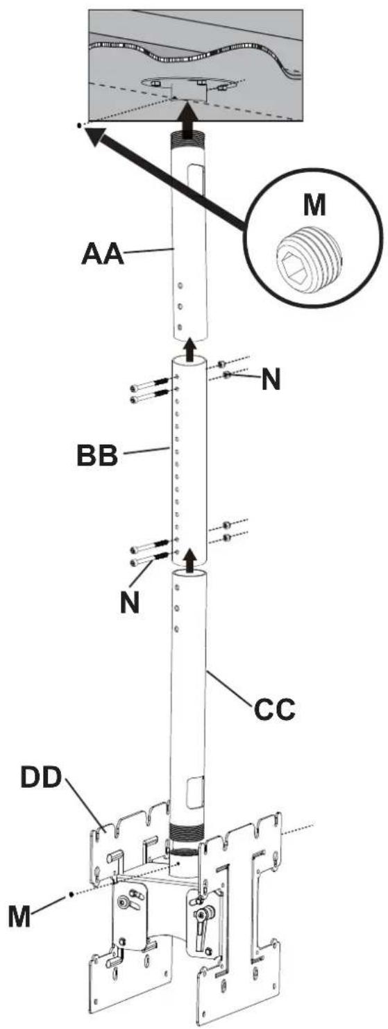
Attach threaded end of adjuster tube (AA) to threaded fitting in ceiling plate. Tighten securely aligning slot in end of adjuster tube (AA) with one of the holes in the side of threaded fitting. Insert and tighten one M4 x 3 mm hexagon filler screw (M) to lock adjuster tube (AA) to threaded fitting.
WARNING
- Installer must verify that the ceiling will safely support the combined weight of all attached equipment and hardware.

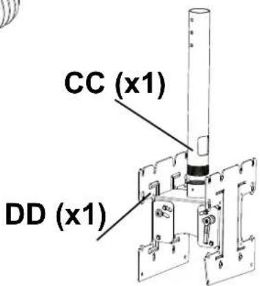
Slide extension pipe (BB) over adjuster tube (AA) to the desired height. Attach with two M8 x 60 mm hexagon fillister head screws (K) and lock nut (K).
Slide extension pipe (CC) over adjuster tube (BB) to the desired height. Attach with two M8 x 60 mm hexagon fillister head screws (N) and lock nut (N).
Attach threaded end of adjuster tube (DD) to threaded fitting in (DD) and lock nut (M).
WARNING
- Adjuster tube must be fully threaded (six or seven full turns) onto threaded fitting in ceiling plate and then locked with screw (C).
Attaching display mounting plate to a Screen with a VESA Mounting Pattern
Choose hole pattern as shown in detail 3 for VESA mounting pattern. Begin with the shortest length screw, hand thread through adapter plate into screen as shown in detail 4. Screw must make at least three full turns into the mounting hole and fit snug into place. Do not over tighten. If screw cannot make three full turns into the screen, select a longer length screw from the fastener pack. Repeat for remaining mounting holes. Securely tighten screws.
NOTE: Spacers do not have to be used, depending upon the type of screen.
| Mounting Patterns | ||
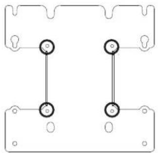 VESA® 100 x 100 VESA® 100 x 100 | 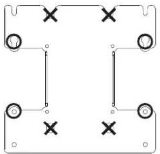 VESA® 200 x 100 VESA® 200 x 100 | 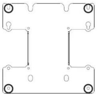 VESA® 200 x 200 VESA® 200 x 200 |
| DETAIL 3 | ||
| VESA® 100 x 100 | VESA® 200 x 100 VESA | ® 200 x 200 | |
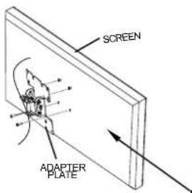 | 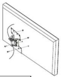 | 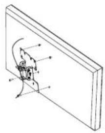 | |
| NOTE: For screens with a hole pattern in a pocket, spacers go between adapter plate and screen. | DETAIL 4 | ||
For Flat Back Screen
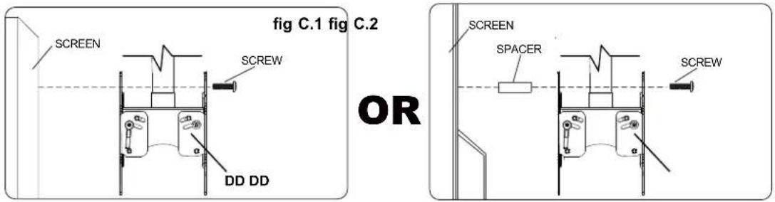
Select the small, medium, large or extra large screws from the baffled .Fastener pack then attach screen brackets(DD) to screen following figure C.1 or C.2 on page 7.
Insert two for 200x200 & 200x100 VESA patterns appropriate sized bolts into the top two mounting holes on the back of your display as shown in fig.1 Leave approx. 1/4" of exposed thread.
Lift the display and hook it on to the display mounting plate by lowering the exposed portion of the top screws down the notches on the top edge of the plate for a 200x200 pattern or into the key hole.
Once in position, attach the bottom two for a 200x200 pattern bolts to secure the display to the mounting plate as shown in fig.2
WARNING
- Do not lift more weight than you can handle. Use additional man power or mechanical lifting equipment to safely handle placement of the screen.
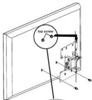
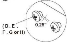
fig.2
fig.1
Tilt Adjustmentd
Adjust tension knob on side of mount as shown in fig. 1 to desired tension to balance your screen size and weight.
The tension knob, without changing the bracket tension, can be pulled out, away from the bracket and turned independently of the knob post for readjustment as shown in fig 2
Push or pull from top or bottom of screen to adjust tilt as shown. The tilt can be adjusted to a maximum of -5^ forward or +15^ backward
CAUTION
- Be careful not to pinch fingers when opening and closing mount from the wall.
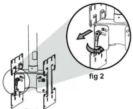
fig1
Wire Management
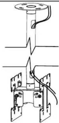
pull cables up and through conduit.
WARNING
- Do not remove or loosen screw while the mount is in use. Doing so may cause the screen to fall.
natural_image
Technical line drawing of a mechanical assembly with no visible text or symbols- WARNING
- Tools Needed for Assembly
- Table of Contents
- Installation to Wood Joist Finished Ceilings, Exposed Wood Joists, or Wood Beam Ceilings
- Installation to Concrete Ceilings
- Installation of Extension Column
- Attaching display mounting plate to a Screen with a VESA Mounting Pattern
- Tilt Adjustmentd
- CAUTION
- Wire Management
Brand : MONOPRICE
Model : 6530
Category : Wall mount