POE-E174 - Wi-Fi Router Planet - Free user manual and instructions
Find the device manual for free POE-E174 Planet in PDF.

| Product Type | Wireless Router with PoE Support |
| Model | POE-E174 |
| Brand | Planet |
| Wi-Fi Standards | IEEE 802.11b/g/n (2.4 GHz) |
| Maximum Wireless Speed | 300 Mbps |
| Ports | 4x 10/100 LAN, 1x 10/100 WAN |
| PoE Input | 802.3af PoE (PD) |
| Power Supply | DC 12V/1A (adapter included) |
| Dimensions | 200 x 150 x 30 mm (approx.) |
| Weight | 350 g (approx.) |
| Antennas | 2x external 5 dBi (detachable) |
| Security | WPA2-PSK, WPA-PSK, WEP, firewall |
| Management | Web-based GUI, firmware upgrade |
| Operating Temperature | 0°C to 40°C |
| Humidity | 10% to 90% non-condensing |
| Mounting | Desktop or wall-mount |
| LED Indicators | Power, WAN, LAN, WLAN, PoE |
| Maintenance | Keep in a dry, ventilated area; clean with a soft dry cloth |
| Spare Parts / Repairability | Power adapter and antennas are user-replaceable; other components require professional service |
| General Information | Designed for small office/home use; supports PoE for flexible deployment |
Frequently Asked Questions - POE-E174 Planet
User questions about POE-E174 Planet
0 question about this device. Answer the ones you know or ask your own.
Ask a new question about this device
Download the instructions for your Wi-Fi Router in PDF format for free! Find your manual POE-E174 - Planet and take your electronic device back in hand. On this page are published all the documents necessary for the use of your device. POE-E174 by Planet.
USER MANUAL POE-E174 Planet
1-Port Ultra PoE to 4-Port 802.3af/at Gigabit PoE Extender
IPOE-E174
User's Manual
Table of Contents
1. Introduction.... 3
1.1 Packet Contents.... 3
1.2 Application Diagram 4
1.3 Key Features....5
1.4 Technical Specifications 7
1.5 Power over Ethernet Budget....10
2. InSTALLATION....11
2.1 Physical Dimensions....11
2.2 Front Panel 12
2.3 Mounting Installation....14
2.3.1 DIN-rail Mounting....14
2.3.2 Wall-mount Plate Mounting ....15
2.4 Connecting IPOE-E174 to Power Source Equipment (PSE) .....16
2.5 Connecting IPOE-E174 to Powered Device (PD)....17
3. Customer Support....19
1. Introduction
1.1 Packet Contents
Thank you for purchasing PLANET IPOE-E174- 1-Port Ultra PoE to 4-Port 802.3af/at Gigabit PoE Extender. Open the box of the IPOE-E174 and carefully unpack it. The box should contain the following items:
■ Industrial Power over Ethernet Extender x 1
■ User's Manual x 1
■ RJ45 Dust Cap x 5
■ Wall Mounting Kit x 1
If any of these are missing or damaged, please contact your dealer immediately; if possible, retain the carton including the original packing material, and use them again to repack the product in case there is a need to return it to us for repair.
1.2 Application Diagram
The IPOE-E174 is designed as the repeater to forward both Gigabit Ethernet data and IEEE 802.3at PoE power, thus extending the range of PoE installation. With just plug and play and without additional power supply and setup, one single IPOE-E174 can increase the PoE range to 200m and drive up four remote PoE IP cameras or wireless access point.

flowchart
graph TD
    A["Power"] --> B["Ultra PoE Injector"]
    B --> C["Switch"]
    D["100meters"] --> E["100meters"]
    E --> F["100meters"]
    F --> G["100meters"]
    G --> H["100meters"]
    H --> I["100meters"]
    I --> J["100meters"]
    J --> K["100meters"]
    K --> L["100meters"]
    L --> M["100meters"]
    M --> N["100meters"]
    N --> O["100meters"]
    O --> P["100meters"]
    P --> Q["100meters"]
    Q --> R["100meters"]
    R --> S["100meters"]
    S --> T["100meters"]
    T --> U["100meters"]
    U --> V["100meters"]
    V --> W["100meters"]
    W --> X["100meters"]
    X --> Y["100meters"]
    Y --> Z["100meters"]
    Z --> AA["100meters"]
    AA --> AB["100meters"]
    AB --> AC["100meters"]
    AC --> AD["100meters"]
    AD --> AE["100meters"]
    AE --> AF["100meters"]
    AF --> AG["100meters"]
    AG --> AH["100meters"]
    AH --> AI["100meters"]
    AI --> AJ["100meters"]
    AJ --> AK["100meters"]
    AK --> AL["100meters"]
    AL --> AM["100meters"]
    AM --> AN["100meters"]
    AN --> AO["100meters"]
    AO --> AP["100meters"]
    AP --> AQ["100meters"]
    AQ --> AR["100meters"]
    AR --> AS["100meters"]
    AS --> AT["100meters"]
    AT --> AU["100meters"]
    AU --> AV["100meters"]
    AV --> AW["100meters"]
    AW --> AX["100meters"]
    AX --> AY["100meters"]
1.3 Key Features
Physical Port
■ 5-port 10/100/1000BASE-T Gigabit RJ45 interface
◆ 1-port data + power input
◆ 4-port data + power output
Power over Ethernet
■ 1-port data + power input
◆ Complies with ultra Power over Ethernet end-span and mid-span PD
◆ Complies with IEEE 802.3at High Power over Ethernet end-span / mid-span PD
◆ Supports PoE input power up to 60 watts
■ 4-port data + power output
◆ Complies with IEEE 802.3af / IEEE 802.3at Power over Ethernet / end-span PSE
◆ Up to 4 IEEE 802.3af / 802.3at devices powered
◆ Supports PoE power up to 30.8 watts for each PoE port
◆ Auto detects powered device (PD)
■ Extends the range of PoE to an additional 100 meters (328ft.)
■ Forwards both Ethernet data and PoE power to remote device
Layer 2 Features
■ Hardware based 10/100Mbps, half / full duplex and 1000Mbps full duplex mode, flow control, auto-negotiation and auto MDI/MDI-X
■ Features Store-and-Forward mode with wire-speed filtering and forwarding rates
■ IEEE 802.3x flow control for full duplex operation and back pressure for half duplex operation
■ Integrates address look-up engine, supporting 8K absolute MAC addresses
■ 9K jumbo frame support in 1000Mbps duplex mode
■ Automatic address learning and address aging
■ Supports CSMA/CD protocol
Industrial Case / Installation
■ IP30 aluminum case protection
■ DIN rail and wall-mount design
■ Supports EFT protection for 6000V DC power, and 6000V DC Ethernet ESD protection
■ -40 to 75 degrees C operating temperature
■ No external power cable required for installation
■ Plug and Play installation
Standard Compliance
■ IEEE 802.3 10BASE-T
■ IEEE 802.3u 100BASE-TX
■ IEEE 802.3ab 1000BASE-T
■ IEEE 802.3x Flow Control
■ IEEE 802.3at High Power over Ethernet
■ IEEE 802.3af Power over Ethernet
■ FCC Part 15 Class A, CE

Note
PSE (Power Sourcing Equipment) is a device (switch, or hub for instance) that provides power in a PoE setup. Maximum allowed continuous output power per such device in IEEE 802.3af is 15.4W, and in IEEE 802.3at is 30W.
PD (Powered Device) is a PoE-enabled terminal by PSE and thus consumes energy, such as PoE IP Phones, PoE IP cameras, PoE wireless access points, etc.
1.4 Technical Specifications
| Model IPOE-E174 | |
| Hardware Specifications | |
| Network Connector | PoE In Port1 x 10/100/1000BASE-T Ethernet with ultra PoE "Data + DC" in, auto MDI/MDI-X, auto-negotiation RJ45 connectorPoE Out Port4 x 10/100/1000BASE-T Ethernet with IEEE 802.3af/at PoE "Data + DC" out, auto MDI/MDI-X, auto-negotiation RJ45 connector |
| Switch Architecture Store-and-Forward switch architecture | |
| MAC Address Table | 8K MAC address table with auto learning function |
| Data Buffer 1Mbit | |
| Switch Fabric 10Gbps | |
| Switch Throughput 7.44Mpps @ 64Bytes | |
| Flow Control | IEEE 802.3x pause frame for full duplex Back pressure for half duplex |
| Jumbo Frame 9Kbytes | |
| ESD Protection 6KV DC | |
| EFT Protection 6KV DC | |
| Enclosure IP30 aluminum metal case | |
| Installation DIN rail kit and wall-mount ear | |
| LED Display | System: PWR (Green)Power Input: Midspan in (Green)Power Input: Endspan in (Green)PoE Power Usage (%): 25 (Green)PoE Power Usage (%): 50 (Green)PoE Power Usage (%): 75 (Green)PoE Input Port: LNK/ACT (Green)PoE Input Port: PoE in (Orange)Per PoE Output Port: LNK/ACT (Green)Per PoE Output Port: PoE-in-Use (Orange) |
| Cable | Twisted-pair cable:10BASE-T: 2-pair UTP Cat. 3,4,5, up to 100 meters100BASE-TX: 2-pair UTP Cat. 5, 5e up to 100 meters1000BASE-T: 4-pair UTP Cat. 5e,6 up to 100 meters |
| Dimensions(W x D x H) | 135 x 87.8 x 56 mm |
| Weight 715g | |
| Power Consumption | 60 watts / 204.6BTU (Full loading with PoE function) |
| Power over Ethernet | |
| PoE Standard | PoE in PortIEEE 802.3at High Power over Ethernet end-span / mid-span PD class 4 PDPer PoE out PortIEEE 802.3at High Power over Ethernet end-span PSEIEEE 802.3af Power over Ethernet end-span PSE |
| PoE Power | PoE in Port50~57V DC, max. 60 wattsPer PoE out Port44~55V DC, max. 30.8 watts |
| Power Pin Assignment | PoE in Port1/2(+), 3/6(-); 4/5(+), 7/8(-)Per PoE out Port1/2(+), 3/6(-) |
| PoE Power Budget | 50 watts (max.) @ Ultra PoE input20 watts (max.) @ IEEE 802.3at PoE+ inputNo support @ IEEE 802.3af PoE input |
| Standards Conformance | |
| Regulation Compliance | FCC Part 15 Class A, CE |
| Stability Testing | IEC60068-2-32 (Free fall)IEC60068-2-27 (Shock)IEC60068-2-6 (Vibration) |
| Standards Compliance | IEEE 802.3 EthernetIEEE 802.3u Fast EthernetIEEE 802.3ab Gigabit EthernetIEEE 802.3x Flow ControlIEEE 802.3af Power over EthernetIEEE 802.3at High Power over Ethernet |
| Environment | |
| Operating | Temperature: -40 ~ 75 degrees CRelative Humidity: 5 ~ 95% (non-condensing) |
| Storage | Temperature: -40 ~ 85 degrees CRelative Humidity: 5 ~ 95% (non-condensing) |
1.5 Power over Ethernet Budget
The following table lists how many PoE devices can be powered by IPOE-E174:
| Power Source | PoE Output Budget* | Max. Number of PDs supported | |
| PLANET Ultra PoE PSE | 50 watts max. | Class 4 PD@25-watt | 2 units |
| Class 3 PD@15-watt | 3 units | ||
| Class 2 PD@7-watt 4 | units | ||
| IEEE 802.3at PoE+ PSE | 20 watts max. | Class 4 PD@25-watt | 0 |
| Class 3 PD@15-watt | 1 unit | ||
| Class 2 PD@7-watt 2 | units | ||
| IEEE 802.3af PoE PSE | 10 watts max. Cl | Class 2 PD@7-watt 1 unit | |
Remarks
- The PoE Output Budget means the 4-port PD aggregated power output. The aggregated power consumption will be below 50 watts if with ultra PoE PSE.
- Please check the power input LED (60W PoE) for optimal power output. Both mid-span and end-span LEDs should be turned on for maximum capability.
2. InSTALLATION
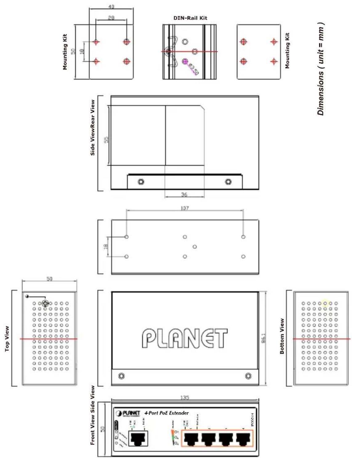
2.1 Physical Dimensions
IPOE-E174 1-port Ultra PoE to 4-port 802.3af/at Gigabit PoE Extender dimensions (W x D x H): 135 x 87.8 x 56 mm
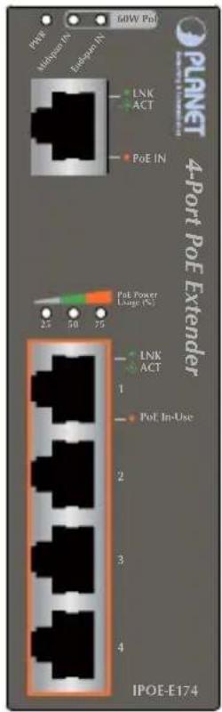
2.2 Front Panel
Figure 2-1 shows the front panel of Industrial Power over Ethernet Extender
text_image
PREF Methiogen IN Inbetgen IN 50W Pol LNK ACT PoE IN PoE Power Lange (%) 25 50 75 4 3 2 1 PoE In-Use IPOE-E174Figure 2-1: IPOE-E174 Front Panel
System
| LED Color Function | ||
| PWR Green | Light to indicate IPOE-E174 has power. | |
| Midspan IN | Green | Light to indicate IPOE-E174 is working in midspan mode and offers up to 30-watt power. |
| Endspan IN | Green | Light to indicate IPOE-E174 is working in endspan mode and offers up to 30-watt power. |
PoE Input Por
| LED Color Function | |
| LNK/ACT Green | Light to indicate the port is linked up. |
| Blink to indicate that the IPOE-E174 is actively sending or receiving data over that port. | |
| PoE In Orange Light | to indicate IPOE-E174 has power. |
➢ Per PoE Output Port (Port 1 \~ 4)
| LED Color Function | |
| LNK/ACT Green | Light to indicate the port is linked up. |
| Blink to indicate that the IPOE-E174 is actively sending or receiving data over that port. | |
| PoE In-Use Orange | Light to indicate the port is providing PoE power. |
| OFF to indicate that the Switch is inactively sending or receiving data over that port. |
➢ PoE Power Usage (%)
| LED Color Function | ||
| 25 Green | Light to indicate the system is providing >25% PoE power usage. | |
| 50 Green | Light to indicate the system is providing >50% PoE power usage. | |
| 75 Green | Light to indicate the system is providing >75% PoE power usage. | |
2.3 Mounting Installation
This section describes how to install the Industrial Power over Ethernet Extender and make connections to it. Please read the following topics and perform the procedures in the order being presented.

text_image
NoteIn the installation steps below, this Manual uses IGS-801 (PLANET 8 Port Industrial Gigabit Switch) as an example. However, the steps for PLANET Industrial Power over Ethernet Extender are similar.
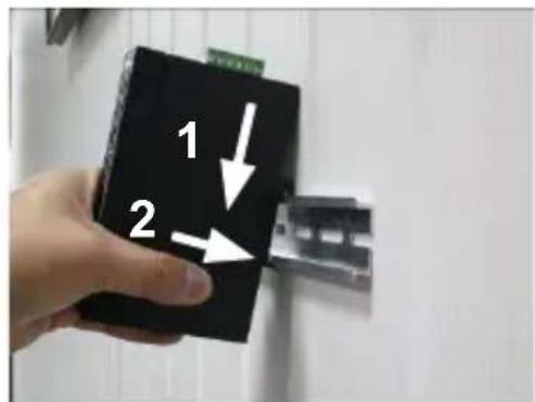
2.3.1 DIN-rail Mounting
Place the Industrial Power over Ethernet Extender on the DIN rail, which is mounted on the wall, and screw it. Just follow the steps below to install the Extender.
Step 1: Lightly insert the bottom of the switch into the track.
text_image
1 2Step 2: Check if the DIN rail is tightly on the track.

natural_image
Black electronic device mounted on a metal bracket (no visible text or symbols)Please refer to the following procedures to remove the Industrial Power over Ethernet Extender from the track.
Step 3: Lightly remove the DIN rail from the track.

text_image
1 22.3.2 Wall-mount Plate Mounting
To mount the Industrial Power over Ethernet Extender on the wall, please follow the instructions described below.
Step 1: To remove the DIN rail from the Industrial Power over Ethernet Extender, loosen the screws.
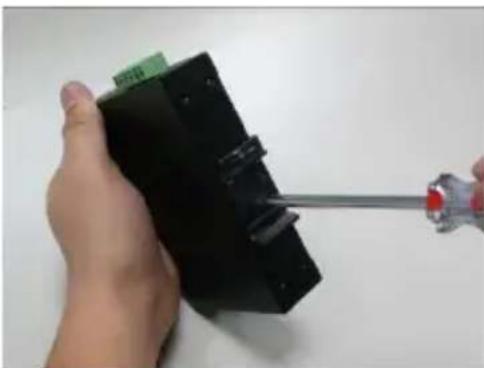
natural_image
Hand holding a black electronic device with a screwdriver inserted, no visible text or symbolsStep 2: Place the wall-mount plate on the rear panel of the Industrial Power over Ethernet Extender.

natural_image
Hand holding a black electronic device with a green label, against a plain white background (no readable text or symbols)Step 3: Use the screws to screw the wall-mount plate on the Industrial Power over Ethernet Extender.
Step 4: Use the hook holes in the corners of the wall-mount plate to hang the Industrial Gigabit Ethernet Switch on the wall.
Step 5: To remove the wall-mount plate, reverse the steps above.
2.4 Connecting IPOE-E174 to Power Source Equipment (PSE)
This section describes how to install the Industrial Power over Ethernet Extender and make connections to it. Please read the following topics and perform the procedures in the order being presented.
There are five RJ45 ports in the Industrial Power over Ethernet Extender, of which the "PoE IN" port functions as "PoE (Data and Power) input" and the "PoE In-Use" port on the other side functions as "PoE (Data and Power) output".
Step 1: Connect a standard CAT-5e/6 UTP cable from Power Source Equipment (PSE), such as PoE Switch, PoE injector hub and single port PoE injector, to the "PoE IN" port of the IPOE-E174.

text_image
PWR Analog port IN 60W PoE PLNET 4-P LNK ACT PoE INStep 2: The PSE delivers both Ethernet Data and PoE power over UTP cable to the IPOE-E174 and the "PoE IN" LED will be lit steadily.

text_image
Note-
When the LED turns steady green, it means the IPOE-E174 is being powered successfully with PoE.
-
If the LED is not lit, please check the remote PSE or the cable connecting to a PC or a network device to see if the cable is correct. Or with an 802.3at device such as the target PD, check whether the power injection is correct.
-
Never connect any non-standard POE PSE to the IPOE-E174, it will damage the device permanently.
2.5 Connecting IPOE-E174 to Powered Device (PD)
Step 1: Connect the additional CAT-5e/6 cable that will be used to connect to the remote Powered Device (PD) to the "PoE In-Use" port of the IPOE-E174.
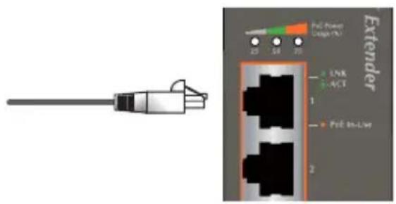
text_image
Extender PcE Power Cable (Hz) LNR ACF 1 PcE On/Low 2Step 2: The "PoE In-Use" port is also the power injector which transmits DC voltage to the CAT-5e/6 cable and transfer data and power simultaneously between the PSE and PD.
Step 3: Once the IPOE-E174 detects the existence of an IEEE 802.3at/af device, the "PoE In-Use" LED indicator will be lit steadily, showing it is providing power.
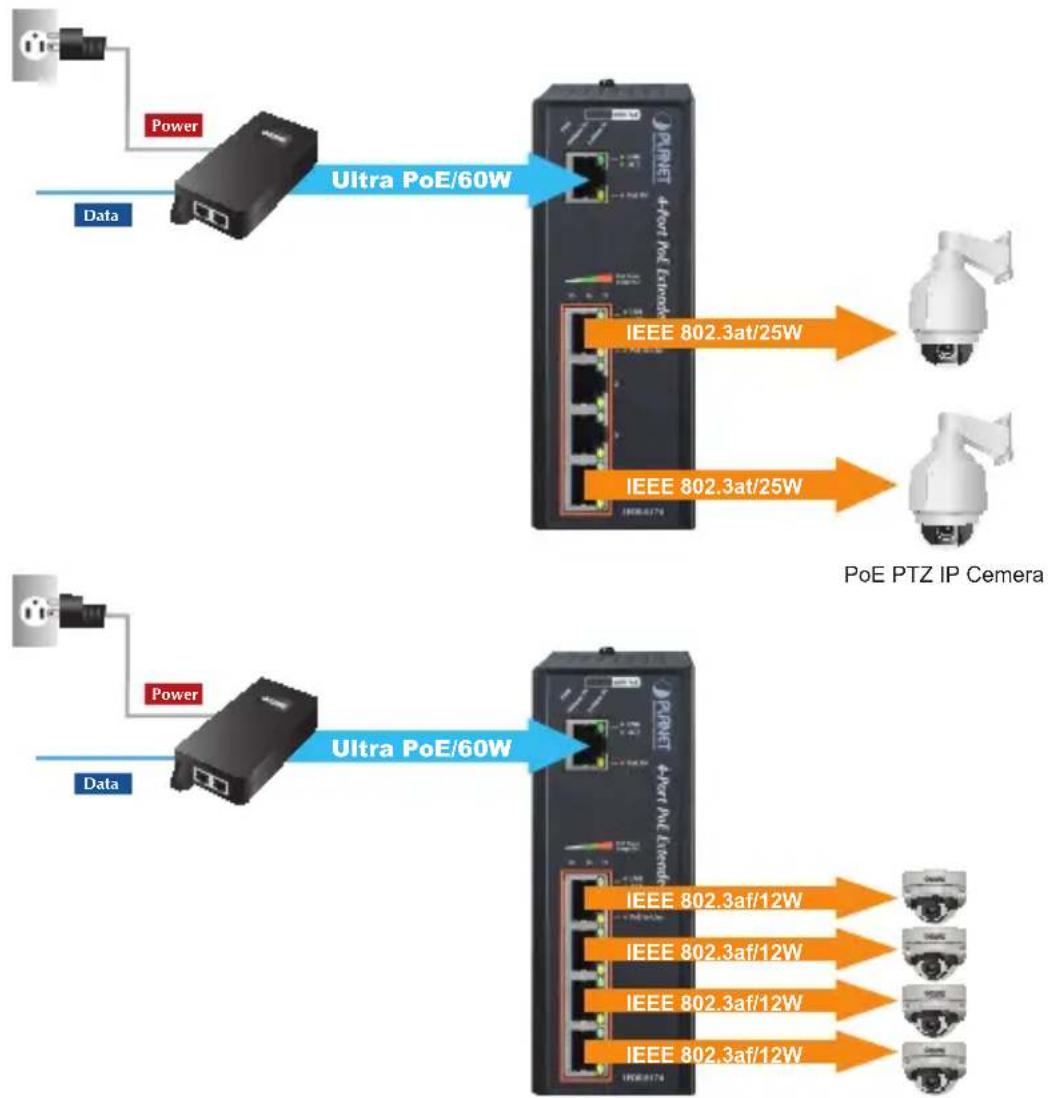
flowchart
graph TD
    A["Power"] --> B["Data"]
    B --> C["Ultra PoE/60W"]
    C --> D["IEEE 802.3at/25W"]
    C --> E["IEEE 802.3at/25W"]
    D --> F["PoE PTZ IP Cemera"]
    E --> F
    G["Power"] --> H["Data"]
    H --> I["Ultra PoE/60W"]
    I --> J["IEEE 802.3af/12W"]
    I --> K["IEEE 802.3af/12W"]
    I --> L["IEEE 802.3af/12W"]
    I --> M["IEEE 802.3af/12W"]
PoE Dome IP Camera

Note
- If the connected device is not fully complying with IEEE 802.3af/at standard or in-line power device, the PoE In-Use LED indicator of the IPOE-E174 will not be lit steadily.
- According to IEEE 802.3af/at standard, the IPOE-E174 will not inject power to the cable if not connecting to a standard IEEE 802.3af/at device.
- DONOT connect any PSE to port 1 \~ port 4 of the IPOE-E174, it may damage the device permanently.
3. Customer Support
Thank you for purchasing PLANET products. You can browse our online FAQ resource and User's Manual on PLANET Web site first to cl could solve your issue. If you need more support information, please contact PLANET switch support team.
PLANET online FAQ:
http://www.planet.com.tw/en/support/faq.php?type=1
Switch support team mail address:
support_switch@planet.com.tw
Copyright © PLANET Technology Corp. 2014.
Contents are subject to revision without prior notice.
PLANET is a registered trademark of PLANET Technology Corp. All other trademarks belong to their respective owners.