C4CCTVKITD4TB - Security Camera CONCEPTRONIC - Free user manual and instructions
Find the device manual for free C4CCTVKITD4TB CONCEPTRONIC in PDF.

User questions about C4CCTVKITD4TB CONCEPTRONIC
0 question about this device. Answer the ones you know or ask your own.
Ask a new question about this device
Download the instructions for your Security Camera in PDF format for free! Find your manual C4CCTVKITD4TB - CONCEPTRONIC and take your electronic device back in hand. On this page are published all the documents necessary for the use of your device. C4CCTVKITD4TB by CONCEPTRONIC.
USER MANUAL C4CCTVKITD4TB CONCEPTRONIC
User's installation and operation Manual
Important Safeguards and Warding
Do not place heavy objects on the DVR.
Do not let any solid or liquid fall into or infiltrate the DVR
Please brush printed circuit boards, connectors, fans, machine box and so on regularly. Before the dust cleaning please switch off the power and unplug it.
Do not disassemble or repair the DVR by yourself. Do not replace the components by yourself.
Environment
Please place and use the DVR between 0°C and 40°C. Avoid direct sunlight. Stay away from heat source.
Do not install the DVR in the damp environment.
Do not use the DVR in smoky or dusty environment.
Avoid collision or strong fall.
Please insure the DVR level installation in a stable workplace.
Please install in ventilated place. Keep the vent clean.
Use within the rating input and output scope.
Directory
1 Production Introduction....4
1.1 Product overview ....4
1.2 Main functions ....4
2 Open-package check and cable connections....5
2.1 Open-package check....5
2.2 Hard disk installation....6
2.3 Front panel 7
2.5 Rear panel 7
2.6 Audio and video input and output connections....7
2.6.1 Video input connections ....7
2.6.2 Video output connections and options 8
2.6.3 Audio signal input 8
2.6.4 Audio signal output....9
PTZ decoder connections....9
3 Basic operation....9
3.1 Turn on....9
3.1 Turn off 10
3.3 System Login ....10
3.4 Preview ...... 11
3.5 Desktop shortcut menu....11
3.5.1 Main menu....12
3.5.2 Playback 12
There are two methods for you to play the video files in the hard disk....12
3.5.3 Record Control....14
3.5.4 PTZ control....14
3.5.5 Color setting....20
3.5.7 Output Adjust....20
3.5.8 Logout....21
4 Main menu 22
4.2 Record....24
4.2.2 Playback 25
4.2.3 Backup 25
4.3 Alarm Function 27
4.3.1 Motion Detect....27
4.3.2 Video Blind .... 30
4.3.3 Video Loss....31
4.3.4 Abnormal....32
4.4 System setup ....33
4.4.1 General 33
4.4.2 Encode setup....34
4.4.3 Network setup....36
4.4.4 NetService....37
【Enable】Click Enable, then all settings will be available....41
4.4.5 GUI Display 43
4.4.6 PTZ device /RS485 device 44
4.4.7 Tour....45
4.4.8 Channel manage 46
4.5 Advanced....51
4.5.1 HDD Manage ....51
4.5.2 Account 51
4.5.3 Online user ....54
4.5.4 Output adjust....55
4.5.5 Auto Maintain ....55
4.5.6 Restore....55
4.5.7 Upgrade....56
4.5.9 Import / Export....56
4.6 Info....57
4.6.1 HDD info ....57
4.6.2 BPS....58
4.6.3 LOG....58
4.6.4 Version....59
4.7 Shut down system 59
Chapter 5: Cloud Technology Basic Operation....60
6 FAQ and maintenance 65
6.1 FAQ....65
6.2 Maintenance....71
Appendix 1.Remote controller operation (Optional) 72
Appendix 2.Mouse operation (optional) ....73
Appendix 3. Hard disk capability calculation....74
1 Production Introduction
1.1 Product overview
The series DVR is designed specifically for security and defence field which is an outstanding digital surveillance product. It introduces embedded LINUX operating system which is more stable. It introduces standard H.264mp video compressed format and G.711A audio compressed format which insures the high quality image, low error coding ratio and single frame playing. It introduces TCP/IP network technology which achieves the strong network communication ability and telecommunication ability.
The series DVR can be used individually or online applied as a part of a safety surveillance network. With the professional network video surveillance software it achieves the strong network communication ability and telecommunication ability.
The series DVR can be applied in the bank, telecom, electric power system, judicial system, transportation, intelligent housing, factory, storehouse, water conservancy and so on.
1.2 Main functions
Real-time surveillance
- spot interface、analog interface、VGA interface and HDMI interface, surveillance function through monitor or display.
Storage
·non-working hard disk dormancy processing which is convenient to radiate heat, reduce power and extend the life-span
· special storage format which insures the data safety
Compression
· real-time compression by individual hard disk which insures the audio and video signal stable synchronization
Backup
· through SATA interface and USB interface such as USB equipment, removable hard disk and so on
· through net download the files in the hard disk
Playback
· individual real-time video recording as well as searching, playback, network surveillance, recording check, downloading and so on
· multi-playback mode
· zoom at arbitrary region
Net operating
· through net tele-surveillance in the real time
- tele-PTZ control
- tele-recording check and real-time playback
Alarm linkage
- Alarm activated video record, tour ,message, buzzer, e-mail, ftp
Communication interface
- RS485 interface which fulfills the alarm input and PTZ control
· standard ethernet network interface which fulfills the telecommuting function
Intelligent operating
· mouse action function
· fast copy and paste operating for the same setting
2 Open-package check and cable connections
2.1 Open-package check
When you receive the DVR, please check first
First, please check whether there is any visible damage to the package appearance. The protective materials used for the package of the DVR can protect most accidental clashes during transportation.
Then, please open the box and get rid off the plastic protective materials. Check whether there is any visible damage to the DVR appearance.
At last, please open the machine crust and check the data wire in the front panel, power wire, the connection between the fan power and the main board.
1.Front panel and rear panel
The key function specification in the front panel and the interface specification in the real panel are in the specification.
Please check the product type in the front panel whether is accordant with the product type you order.
The label in the real panel is very important for the after service. Please protect it carefully. When you contact us for after service, please provide the product type and serial number in the label.
2.Check
After open the cover, you should check if it has obvious damage trace, also please check the front panel data cable, power cord and motherboard's connection are loose or not.
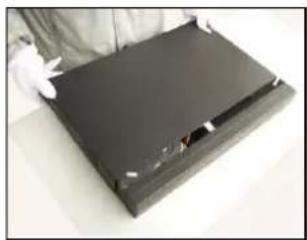
2.2 Hard disk installation
For the first use, please install the hard disk, this machine box can install one or two hard disk(no limited capacity).

natural_image
Hand holding a small yellow object placed on a dark rectangular electronic device (no visible text or symbols)①disassemble the screw
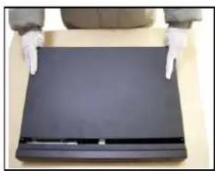
natural_image
Person wearing gloves standing behind a black rectangular object (no visible text or symbols)②disassemble the cover
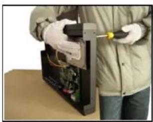
natural_image
Person in protective gear handling electronic components on a mechanical device (no visible text or symbols)③fix the screw of hard disk

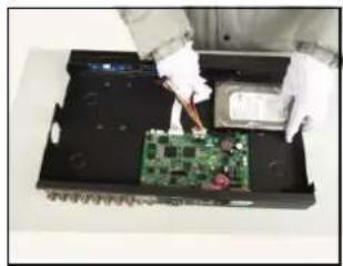
natural_image
Person in protective gear handling a black metal bracket with a yellow tool, against a plain beige background (no text or symbols visible)④fix the screw of hard disk
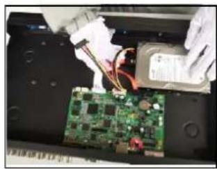
natural_image
Close-up of hands installing a green circuit board with power supply components (no visible text or symbols)⑤connect the data wire
natural_image
Person in white gloves working on a green circuit board inside a black electronic device (no visible text or symbols)⑥connect the power wire
natural_image
Person holding a dark rectangular object with a white clip, possibly a device or panel (no visible text or symbols)⑦cover the machine

natural_image
Person in gloves handling a black electronic device with a yellow tool (no visible text or symbols)⑧fix the cover
2.3 Front panel
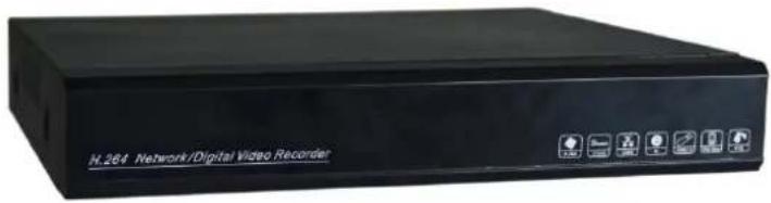
text_image
H. 264 Network/Digital Video Recorder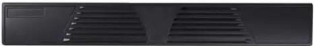
natural_image
Front view of a black ventilation grille with two slatted panels (no text or symbols visible)2.5 Rear panel
The rear panel of 4/8channel series
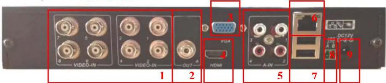
text_image
7 8 VIDEO-IN 5 6 3 4 VIDEO-IN 1 2 OUT A 3 VGA HDMI 4 A-IN 2 6 7 8 DC12V 9- Video input (4channel:Video1-4,8channel:Video5-8)
- Audio output
- VGA output
- HDMI output
- Audio input
- Network port
- USB port
- RS485 port
- Power input
2.6 Audio and video input and output connections
2.6.1 Video input connections
The video input port is BNC connector plug. The demand of input signal is PAL/NTSC BNC(1.0V _P-P ,75Ω).
The video signal must be accorded with the state standard which has the high signal to noise ratio,
low aberration and low interference. The image must be clear and has natural color in the appropriate brightness.
Insure the camera signal stable and credible
The camera should be installed in the appropriate location where is away from backlighting and low illumination or adopts the better backlighting and low illumination compensation.
The ground and power supply of the camera and the DVR should be shared and stable.
Insure the transmission line stable and credible
The video transmission line should adopt high quality coaxial pair which is chosen by the transmission distance. If the transmission distance is too far, it should adopt shielded twisted pair, video compensation equipment and transmit by fiber to insure the signal quality.
The video signal line should be away from the electro magnetic Interference and other equipments signal lines. The high voltage current should be avoided especially.
Insure the connection stable and credible
The signal and shield lines should be firm and connected credible which avoid false and joint welding and oxidation.
2.6.2 Video output connections and options
The video output is divided into PAL/NTSC BNC(optional) and VGA /HDMI output.
When replace the monitor by the computer display, there are some issues to notice
1、Do not stay in the turn-on state for a long time.
2、Keep the computer display normal working by demagnetizing regularly.
3、Stay away from the electro magnetic Interference.
2.6.3 Audio signal input
Audio port is RCA connection.
The input impedance is high so the tone arm must be active.
The audio signal line should be firm and away from the electro magnetic Interference and connected credible which avoid false and joint welding and oxidation. The high voltage current should be avoided especially.
2.6.4 Audio signal output
Commonly the output parameter of DVR audio signal is greater than 200mv 1KΩ(RCA) which can connect the low impedance earphone and active sound box or other audio output equipments through power amplifier. If the sound box and the tone arm can not be isolated, howling phenomena is often existed. There are some methods to deal with the above phenomena.
1、Adopt better directional tone arm.
2、Adjust the sound box volume to be under the threshold that produces the howling phenomena.
3、Use fitment materials that absorb the sound to reduce reflection of the sound.
4、Adjust the layout of the sound box and the tone arm.
PTZ decoder connections
A. The grounding of the PTZ decoder and DVR must be shared otherwise the common-mode voltage will lead to the PTZ control failure. The shielded twisted pair is recommended.
B. Avoid the entrance of high voltage. Make the layout reasonably. Take precaution from the thunder.
C. In the outlying end connect 120 resistance paralleled to reduce the inflection and insure the signal quality.
D. The 485 AB lines of DVR can not connected with other 485 output equipments paralleled.
E. The voltage between the AB lines of the decoder must be less than 5V.
3 Basic operation
Note: The button in gray display indicates nonsupport.
3.1 Turn on
Plug the power supply and turn on the power supply switch. Power supply indicator light shining indicates turning on the video recorder. After the startup you will hear a beep. The default setting of video output is multiple-window output mode. If the startup time is within the video setting time, the timing video recording function will start up automatically. Then the video indicator light of corresponding channel is
shining and the DVR is working normally.
Note:1. Make sure that the input voltage corresponds with the switch of the DVR power supply.
- Power adapter supply demands: 12V±10%.
3.1 Turn off
There are two methods to turn off the DVR. Entering [main menu] and choosing [turn off] in the [turn off the system] option is called soft switch. Pressing the power supply switch is called hard switch.
1、Auto resume after power failure
If the DVR is shut down abnormally, it can automatically backup video and resume previous working status after power failure.
2、Replace the hard disk
Before replacing the hard disk, the power supply switch in the real panel must be turned off.
3、Replace the battery
Before replacing the battery, the setting information must be saved and the power supply switch in the real panel must be turned off. The DVR uses button battery. The system time must be checked regularly. If the time is not correct you must replace the battery, we recommend replacing the battery every year and using the same battery type.
Note: The setting information must be saved before replacing the battery otherwise information will lose.
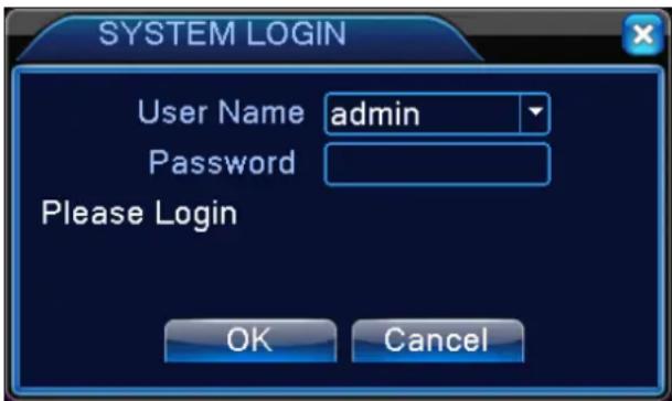
3.3 System Login
When the DVR boots up, the user must login and the system provides the corresponding functions with the user purview. There are three user settings. The default user name is admin, default password is null.
text_image
SYSTEM LOGIN User Name admin Password Please Login OK CancelPicture 3.1 System Login
Password protection: If the password is continuous wrong three times, the alarm will start. If the password is continuous wrong five times, the account will be locked. (Through reboot or after half an hour, the account will be unlocked automatically).
For your system security, please modify your password after first login.
3.4 Preview
You can right click mouse to choose the switch between the windows.
The system date, time and channel name are shown in each viewing window. The surveillance video and the alarm status are shown in each window.
| 1 |  | Recording status | 3 |  | Video loss |
| 2 |  | Motion detect | 4 |  | Camera lock |
Table 3.1 Preview icon
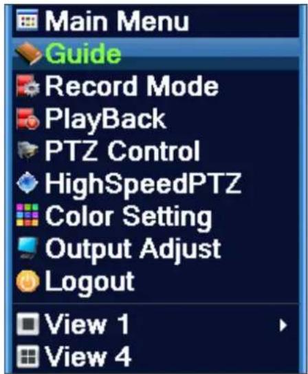
3.5 Desktop shortcut menu
In preview mode you can right click mouse to get a desktop shortcut menu, as the picture 3.2 shows. The menu includes: main menu, record mode, playback, PTZ control, High Speed PTZ, Alarm Output, color Setting, Output adjust, Logout, view mode shift ,spot.
text_image
Main Menu Guide Record Mode Playback PTZ Control HighSpeedPTZ Color Setting Output Adjust Logout View 1 View 44channel
8channel
Picture 3.2 Shortcut Menu
*compare to analog/hybrid mode's shortcut menu, the full digital mode do not have color setting function.
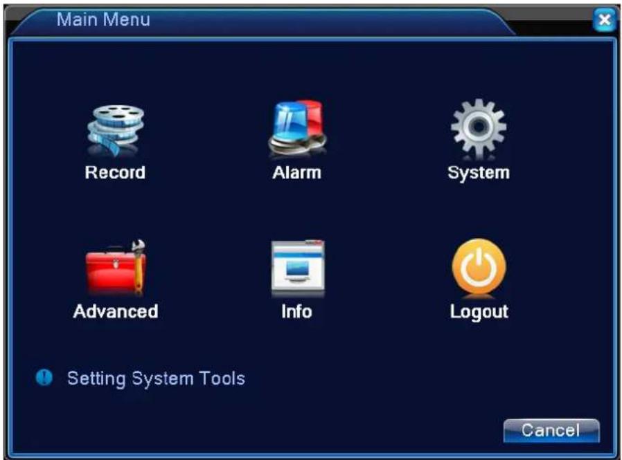
3.5.1 Main menu
When you login, the system main menu is shown as below.
text_image
Main Menu Record Alarm System Advanced Info Logout Setting System Tools CancelPicture3.3 Main Menu
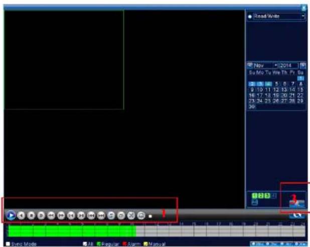
3.5.2 Playback
There are two methods for you to play the video files in the hard disk.
1、In the desktop shortcut menu.
2、Main menu>Record->Playback
Note: The hard disk that saves the video files must be set as read-write or read-only state.(4.5.1).
text_image
Read Write Nov 2014 Sw Mo Tu We Th Pr Sa 5 6 7 8 9 10 11 12 13 14 15 16 17 18 19 20 21 22 23 24 25 26 27 28 29 30 18 19 20 3 Sync Mode All Regular Alarm Manual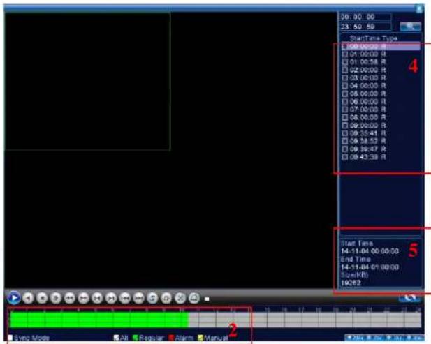
text_image
00:00:00 23:59:56 Start Time Type 00:00:00 R 01:00:00 R 02:00:00 R 03:00:00 R 04:00:00 R 05:00:00 R 06:00:00 R 07:00:00 R 08:00:00 R 09:00:00 R 09:35:41 R 09:38:53 R 09:38:47 R 09:43:39 R Start Time 14:11-04 00:00:00 End Time 14:11-04 6/1/00:00 Size(KB) 19262 Sync Mode All Regular Alarm ManualPicture 3.4 video playback
-
Playback control
-
Process bar
-
file searching
-
listed files
-
file information
【Listed files】Look up the listed files that accord with the searching criteria.
【File information】Look up the found file information.
【Playback control】 See detail in below chart
| Key | Function | Key | Function |
 | Play/Pause |  | Backward play |
| [3008] | Slow forward | [1X3W] | Fast forward |
| [4HT2] | Previous frame |  | Next frame |
| [2XWK] | Previous file |  | Next file |
| [H009] | Round play | [2HWZ] | Full screen |
| [5XXC] | Stop |
Picture 3.5 Playback control key
Note: play under frame by frame, the playback status should be paused firstly.
Special functions:
Accurate playback: Input time (h/m/s) in the time column and then click play button. The system can operate accurate playback according to the searching time.
Local zoom: When the system is in single-window full-screen playback mode, you can drag your mouse in the screen to select a section and then left click mouse to realize local zoom. You can right click
mouse to exit.
Note: When current resolution of the channel is over Max resolution, to playback this channel, will show a Red "X".
3.5.3 Record Control
Please check current channel status: “○” means it is not in recording status, “●” means it is in recording status.
You can use desktop shortcut menu or click [main menu]> [recording function]> [recording set] to enter the recording control interface.
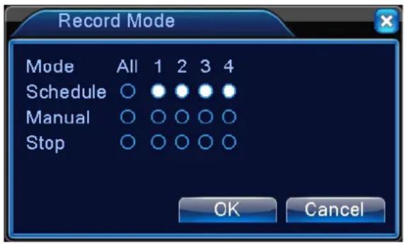
【Schedule】Record according to the configuration.
【Manual】Click the all button and the according channel is recording no matter the channel in any state.
【Stop】Click the stop button and the according channel stops recording no matter the channel in any state.
3.5.4 PTZ control
*PTZ control is a little different between hybrid mode & full digital mode:
Digital channel – the digital channel need link PTZ, the remote device should connect with PTZ and with protocol correctly set also.
Analog channel – Only when the device is connect with PTZ and configure protocol correctly is ok.
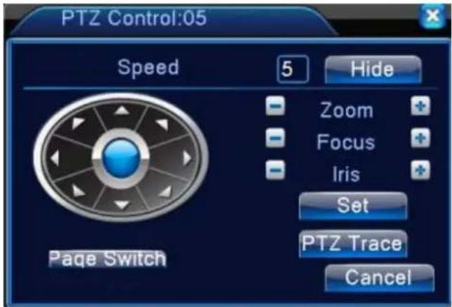
Operation interface is as followed. The functions include: PTZ direction control, step, zoom, focus, iris, setup operation, patrol between spots, trail patrol, boundary scan, assistant switch, light switch, level rotation and so on.
Note1. Decoder A(B)line connects with DVR A(B)line. The connection is right.
-
Click [main menu] >[system configuration] >[PTZ setup] to set the PTZ parameters.
-
The PTZ functions are decided by the PTZ protocols.
text_image
PTZ Control:05 Speed 5 Hide Zoom Focus Iris Set PTZ Trace Cancel Page SwitchPicture 3.10 PTZ setup
【Speed】Set the PTZ rotation range. Default range: 1 \~ 8.
【Zoom】Click - / + button to adjust the zoom multiple of the camera.
【Focus】Click - / + button to adjust the focus of the camera.
【Iris】Click - / + button to adjust the iris of the camera.
【Hide】Current interface will be temporarily hidden after click it.
【Direction control】Control the PTZ rotation. 8 directions control is supportive.(4 directions in Front panel is supportive)
【High speed PTZ】Full-screen show channel image. Left press mouse and control PTZ to rotate orientation. Left press mouse and then rotate the mouse to adjust the zoom multiple of the camera.
【Set】Enter the function operation menu.
【Page switch】Switch between different pages.
Special functions:
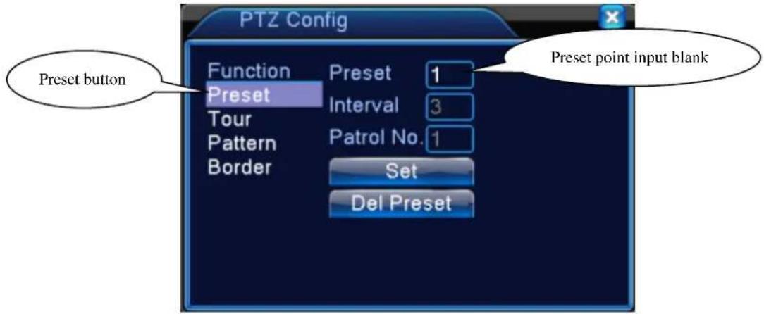
1、Preset
Set a location for the preset, calls the preset points, PTZ automatically turns to the setting position
1) Preset option
Set a location for the preset, procedure is as follows:
Step1: in Picture 3.10, click the Direction button will turn into preset position, click the Settings button to enter Picture 3.11.
Step 2: click the Preset button, then write the preset points in the input blank,
Step 3: click Settings button, return the Picture 3.10 Complete setup, that is the preset points and preset position corresponds.
Clear Preset: Input preset points, click Remove button, remove the preset.
text_image
PTZ Config Function Preset 1 Preset Interval 3 Tour Patrol No. 1 Pattern Border Set Del Preset Preset point input blankPicture 3.11 Preset Settings
2) Preset Point Calls
In Picture 3.10, click Page Shift button, enter PTZ control interface as shown in Picture 3.12. In the input blank, write the preset points, then click Preset button, PTZ turn to the corresponding preset point.
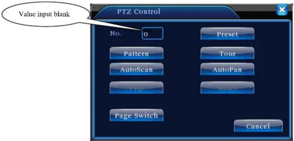
text_image
Value input blank PTZ Control No. 0 Preset Pattern AutoScan AutoPan Flip Reset Page Switch CancelPicture 3.12 PTZ Control
2、Cruise between Points
Multiple preset points connected cruise lines, call cruise between points, the PTZ run around on the line
1) Cruise Between Points Settings
Cruise lines is connected by multiple preset points, setting procedure is as follows:
Step1: In Picture 3.10, the Direction key will turn PTZ to designated location, click Settings button to enter Picture 3.13,
Step 2: click Cruise buttons, the write proper value into the Cruise Line and Preset Points blank, then click Add Preset Points button, complete setting (also can add and delete cruise line which has been set up)
Step 3: repeat step1 and step2, until set out all the preset designated cruise lines.
Remove Preset: Please input preset value in the blank, click Remove Preset button, then remove the preset points.
Remove Cruise Line: Input the number of cruise line, click Remove Cruise Lines button, then remove the cruise lines set.
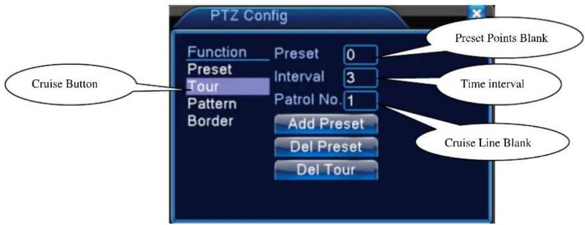
text_image
PTZ Config Function Preset 0 Preset Interval 3 Tour Patrol No. 1 Border Add Preset Del Preset Del Tour Cruise Button Preset Points Blank Time interval Cruise Line BlankPicture 3.13 Cruise Between Points Settings
2) The Calls of Cruise between Points
In Picture 3.10, click Page Shift button, enter PTZ control menu as shown in Picture 3.12. Please input the number of cruise in the value blank, then click Cruise between Points button, PTZ begins to work on the cruise line. Click Stop button to stop cruise.
3、Scan
PTZ also can work on the preset scan line repeatedly.
1) Scan setup
Setting steps:
Step1: In Picture 3.10, click Setup button, enter Picture 3.14;
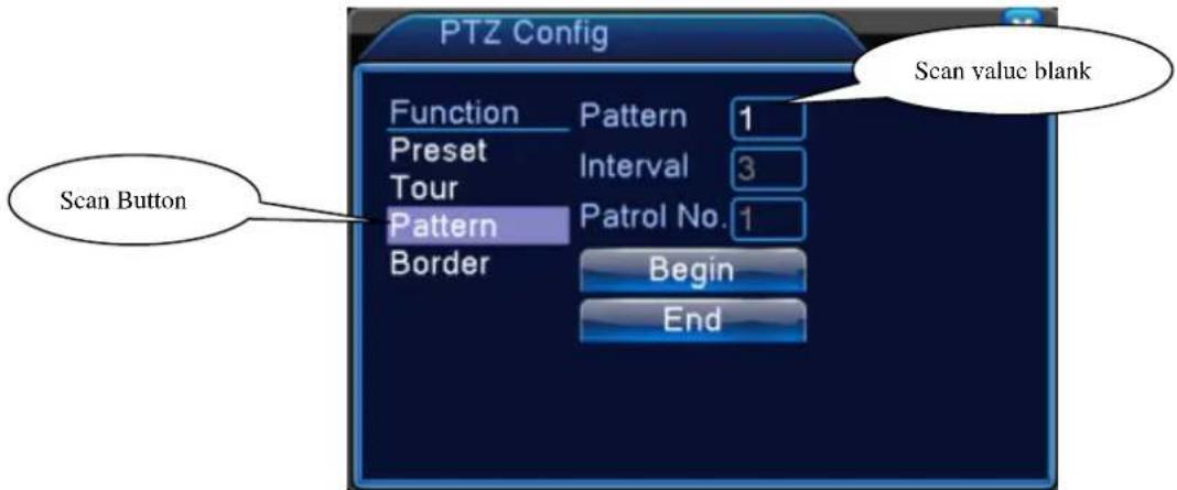
Step2: Click Scan button, the input proper value in the scan value blank;
Step3: Click Start button, enter Picture3.10, here you can set the following items: Zoom, Focus, Aperture, Direction and so on. Click Setup button to go back Picture 3.14
Step4: Click End button to complete setup. Click the right button of the mouse to exit.
text_image
PTZ Config Function Pattern 1 Preset Interval 3 Tour Patrol No. 1 Pattern Border Begin Scan value blank Scan Button EndPicture 3.14 Scan Setup
2) Scan Calls
In Picture 3.10, click Page Shift button, then enter PTZ control menu as shown in Picture 3.12. Please input the number of scan in the value blank, then click Scan button, PTZ begins to work on the scan line. Click Stop button to stop.
4、Boundary Scan
In a horizontal line, set up a line, call scan, PZT repeat operation according to the route
1) Boundary Scan setup
Set a period of horizontal curve for PTZ search path, the steps are as follows:
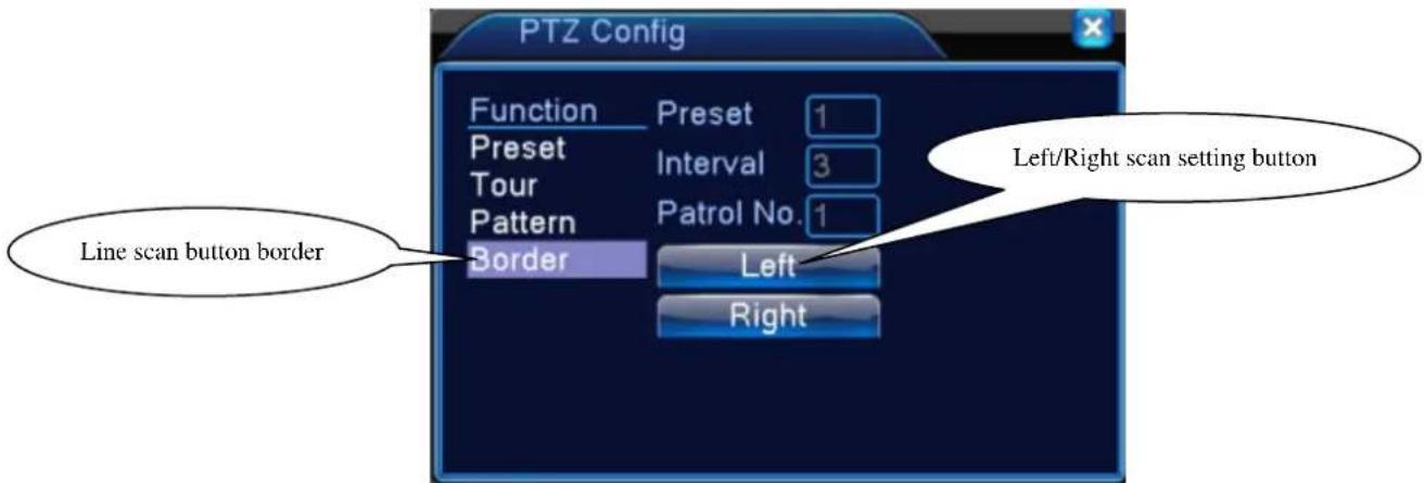
Step1: In Picture 3.10, click Direction button to turn the PTZ to preset direction, then click Setup button enter Picture 3.15, select the left boundary, return to Picture 3.10;
Step2: Please click direction arrows to adjust PTZ direction, click Setup button enter Picture3.15, then select the right boundary, return to Picture 3.10;
Step3: Complete setup, that is the position of left and right boundary
Note: when the left and right scan in one horizontal, the PTZ will cycle rotate from left scan along the reverse direction to the right scan.
When the left and right scan not in the same horizontal, the PTZ will regard the end of horizontal line which connect to left scan as right scan, cycle rotate from left scan along the reverse direction to the right scan.
text_image
PTZ Config Function Preset 1 Preset Interval 3 Tour Patrol No. 1 Pattern Border Left Right Line scan button border Left/Right scan setting buttonPicture 3.15 Boundary Scan Setup
2) Boundary Scan Calls
In Picture 3.10, click Page Shift button, then enter PTZ control menu as shown in Picture 3.12.
Please input the number of scan in the value blank, then click Scan button, PTZ begins to work on the scan line. Click Stop button to stop.
5、Horizontal Rotating
Click Horizontally Rotating button, PTZ begins to rotate horizontally (relative to the original position of the camera). Click the Stop button to stop.
6、Rotate
Click on horizontal Rotating button, PTZ turn around.
7、Reset
PTZ restart, all the data clears to 0.
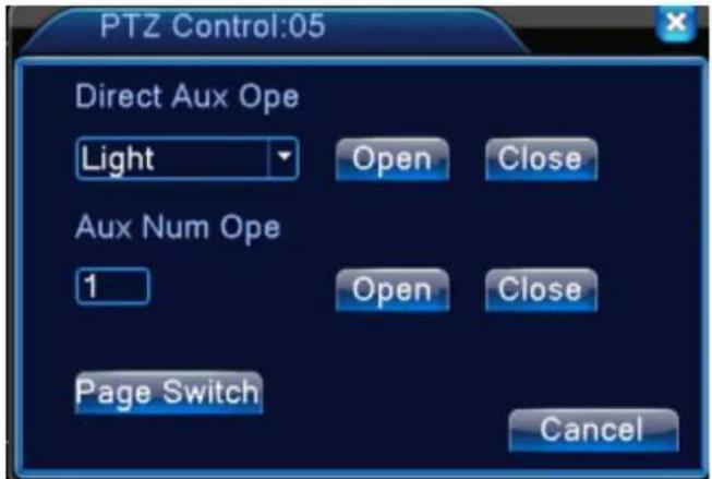
8、Page Shift
In Picture 3.12, click Page Shift button into Picture3.16, setting auxiliary function. Auxiliary number corresponding to auxiliary switch on the decoder.
text_image
PTZ Control:05 Direct Aux Ope Light Open Close Aux Num Ope 1 Open Close Page Switch CancelPicture 3.16 Auxiliary Function Control
【Intuitive Auxiliary Operation】 choose auxiliary equipment, select Open or Close button, switch control;
【Auxiliary Number】The operation of corresponding auxiliary switch according to PTZ agreement;
【Page Shift】In Picture 3.16, click Page Shift button enter the Picture 3.17 PTZ Main Menu, the menu itself can be control by the menu control buttons
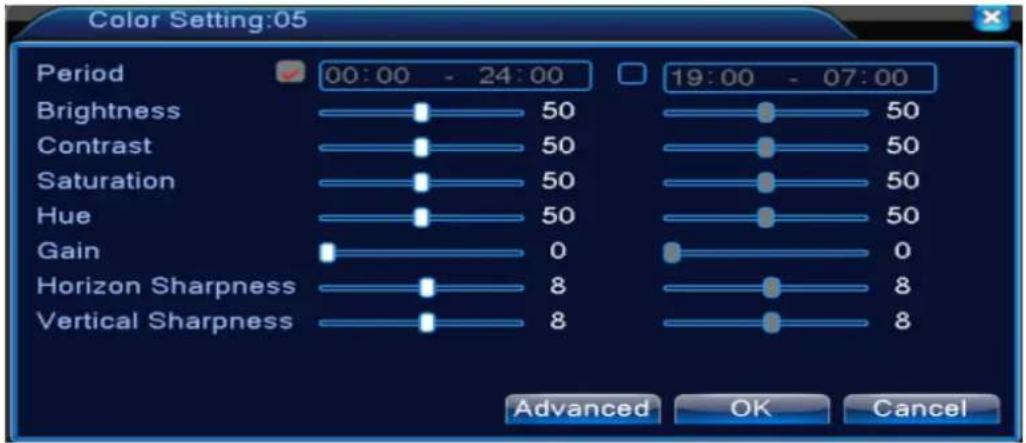
3.5.5 Color setting
*color setting only apply for Hybrid(HVR)/full analog(DVR) mode, and only analog channel can setting.
Set the selective image parameters (current channel for single window display and cursor place for multi-window display). You can use the desktop shortcut menu and enter the interface. The image parameters include: tonality, brightness, contrast, saturation. You can set different parameters at different time sections.
text_image
Color Setting:05 Period 00:00 - 24:00 19:00 - 07:00 Brightness 50 50 Contrast 50 50 Saturation 50 50 Hue 50 50 Gain 0 0 Horizon Sharpness 8 8 Vertical Sharpness 8 8 Advanced OK CancelPicture 3.18 Color Setting
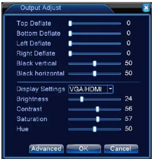
3.5.7 Output Adjust
*Hybrid mode is with black margin vertical & horizontal, while full digital mode without.
Adjust TV output area parameters. You can use the desktop shortcut menu or enter [main menu] > [management tools] > [Output adjust].
text_image
Output Adjust Top Deflate 0 Bottom Deflate 0 Left Deflate 0 Right Deflate 0 Black vertical 50 Black horizontal 50 Display Settings VGA/HDMI Brightness 24 Contrast 56 Saturation 57 Hue 50 Advanced OK CancelPicture 3.19 Output Adjust
Note: The black margin vertical & horizontal at output adjust of hybrid mode is only effect to analog channel.
3.5.8 Logout
Logout, shut down the system or reboot up. You can use the desktop shortcut menu or enter [main menu].

text_image
Logout Logout Shutdown RebootPicture 3.20 Logout/Shutdown/Reboot the system
【logout】Quit the menu. Offer password next entrance.
【shut down】Quit the system. Turn off the power supply.
When press the shut down button, there is schedule hint. After three seconds, the system is shut down. Cancel midway is of no effect.
【reboot】Quit the system. Reboot up the system.
3.5.9 Window switch
Preview in single window/four windows/eight windows/nine windows/sixteen windows according to your choice.
4 Main menu
4.1 Main menu navigation
| Main menu | Sub menu | Function |
| Record | Config | Set the recording configuration, recording type, recording time section |
| playback | Set recording search, recording play, video file storage | |
| backup | Detect backup device, format device, back the selective files | |
| Alarm | Motion detection | Set motion detect alarm channel, sensitivity, area, linkage parameters: defending time section, alarm output, screen hint, recording, screen shot, PTZ, patrol, buzz, email and FTP upload |
| Video blind | Set camera mask alarm channel, sensitivity, linkage parameters: defending time section, alarm output, screen hint, recording, screen shot, PTZ, patrol, buzz, email and FTP upload | |
| Video loss | Set video loss alarm channel, linkage parameters: defending time section, alarm output, screen hint, recording, screen shot, PTZ, patrol, buzz, email and FTP upload | |
| Exception handling | No HDD, HDD error, HDD capacity not enough, network cut, IP Conflict, linkage parameters, screen hint or buzz. | |
| System configuration | General configuration | Set system time, data format, language, hard disk full time operation, machine number, video format, output mode, summertime, stay time |
| Encode configuration | Set main (extra) coding parameter: code mode, resolving ability, frame rate, code stream control, image quality type, code stream value, frame between value, video/audio enable, Note: only Hybrid mode and full analog mode have encode configuration. | |
| Network configuration | Set basic network parameters, DHCP and DNS parameters, network high speed download | |
| Net Service | PPPOE、NTP、Email、IP purview、DDNS parameter | |
| GUI display | Set channel title, preview hint icon state, transparency, cover area time title, channel title fold.Note: only analog channel can set channel name,region cover ,time title,channel title fold. | |
| PTZ configuration | Set channel, PTZ protocol, address, baud rate, date bit, stop bit, checkNote: Hybrid mode shows PTZ configuration, | |
| RS485 Device | Set serial port function, baud rate, date bit, stop bit, checkNote: Full digital mode shows : RS485 Device | |
| Tour | Set patrol mode and interval time | |
| Digital | Set channel mode, check channel status and configure the digital channel, etc.Note: only HVR series support | |
| Management tools | Hard disk management | Set appointed hard disk as read-write disc, read-only disc or redundant disc, clear data, resume date and so on |
| User management | Modify user, team or password. Add user or team. Delete user or team. | |
| Online user | Break the connection with the already login user. Lock the account after break until booting up again. | |
| Output adjust | Adjust upside, downside, nearside, starboard distance, black margin vertical & horizontalNote: only analog channel have black margin vertical & horizontal | |
| Automatic maintenance | Set automatic reboot system and automatic deleting files. | |
| Restore | Resume setup state: common setup, code setup, recording setup, alarm setup, network setup, network service, preview playback, serial port setup, user management | |
| Upgrade | upgrade with external device(like USB) | |
| Device Info | device hardware configuration and message | |
| Import/Export | Export the device's log or configuration to external device(like USB flash disk);Input the configuration with external device(like USB flash disk). | |
| System information | Hard disk information | Display hard disk capability and recording time |
| BPS | Display code stream information | |
| Log information | Clear all log information according to the log video and time | |
| Edition information | Display edition information | |
| Shut down | Logout, shut down or reboot |
4.2 Record
Operations related to record, including: Record, Playback, Backup, Screen shot(only Hybrid mode and full analog have)
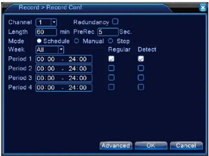
4.2.1 Record Configuration
Set the recording parameters in the surveillance channel. The system is set 24 hours consecutive recording in the first startup. You can enter [main menu] > [recording function] > [recording setup] to set.
Note: There is at least one read-write hard disk. (refer to chapter 4.5.1)
text_image
Record > Record Conf. Channel 1 Length 60 min PreRec 5 Sec. Mode Schedule Manual Stop Week All Period 1 00:00 - 24:00 Period 2 00:00 - 24:00 Period 3 00:00 - 24:00 Period 4 00:00 - 24:00 Redundancy Regular Detect Advanced OK CancelPicture 4.1 Record Configuration
【Channel】Choose the corresponding channel number to set the channel. Choose the all option to set the entire channels.
【Redundancy】Choose the redundancy function option to implement the file double backup function. Double backup is writing the video files in two hard disks. When you do the double backup, make sure that there are two hard disks installed. One is read-write disk and the other is redundant disk. (refer to 4.5.1)
【Length】Set the time length of each video file. 60minutes is default value.
【Pre-Record】Record 1-30 seconds before the action. (time length is decided by the code stream)
【Record mode】Set video state: schedule, manual or stop.
Schedule: Record according to the set video type (common, detection and alarm) and time section.
Manual: Click the button and the according channel is recording no matter the channel in any state.
Stop: Click the stop button and the according channel stops recording no matter the channel in any state.
【Period】Set the time section of common recording, The recording will start only in the set range.
【Record type】Set recording type: regular, detection or alarm.
Regular: Perform the regular recording in the set time section. The video file type is "R".
Detect: Trigger the "motion detect", "camera mask" or "video loss" signal. When above alarm is set as opening recording, the "detection recording" state is on. The video file type is "M".
4.2.2 Playback
Refer to chapter 3.5.2.
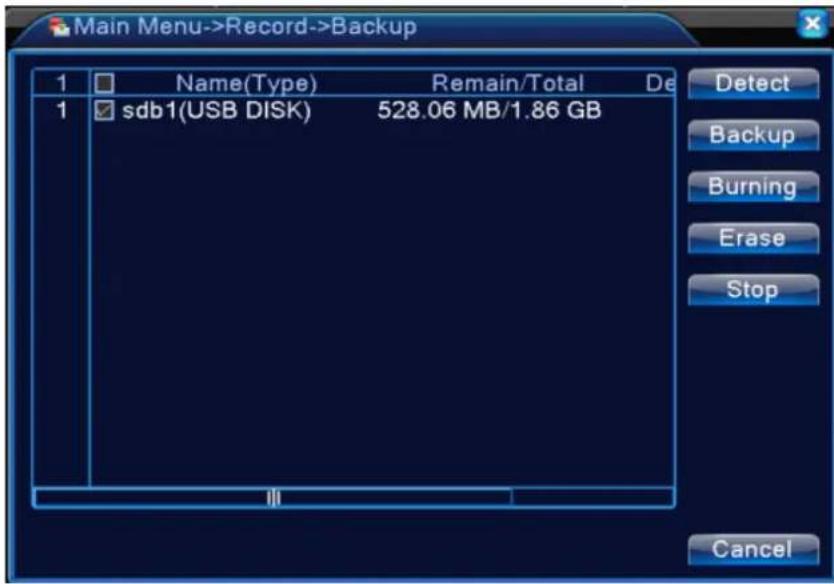
4.2.3 Backup
You can backup the video files to external storage through setup.
Note: The storage must be installed before the file backup. If the backup is terminated, the already backup can playback individually.
text_image
Main Menu->Record->Backup 1 Name(Type) Remain/Total De 1 sdb1(USB DISK) 528.06 MB/1.86 GB Detect Backup Burning Erase Stop CancelPicture 4.2 Backup
【Detect】Detect the storage connected with the DVR such as hard disk or universal disk.
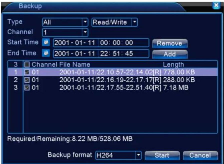
【Backup】Click backup button and the dialog box is popped up. You can choose the backup file according to the type, channel and time.
text_image
Backup Type All Read/Write Channel 1 Start Time 2001 - 01 - 11 00: 00: 00 Remove End Time 2001 - 01 - 11 22: 51: 45 Add 3 Channel File Name Length 1 01 2001-01-11/22.10.57-22.14.02[R] 778.00 KB 2 01 2001-01-11/22.16.19-22.17.17[R] 288.00 KB 3 01 2001-01-11/22.17.55-22.51.40[R] 7.18 MB Required/Remaining:8.22 MB/528.06 MB Backup format H264 Start CancelPicture 4.3 Backup
Remove: Clear the file information.
Add: Show the file information satisfying the set file attributes.
Backup format: configure the backup file format, according to require, can choose

Start/pause: Click the play button to start the backup and click the pause button to stop the backup.
Note: During backup you can exit the page layout to carry out other functions.
【Burning】the file will be burned synchronously after click it.
【Erase】Choose the file to delete and click erasure to delete the file.
【Stop】Stop the backup.
4.3 Alarm Function
Alarm functions include: motion detect, video blind, video loss, abnormality.
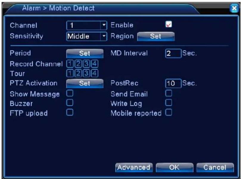
4.3.1 Motion Detect
When system detects the motion signal that reaches the set sensitivity, the motion detect alarm is on and the linkage function is turned on.
Note: "Advanced" button is the same as right click.
*Motion detect function is different between Hybrid mode & Full digital mode:
Digital channel: not only to enable motion detect function at local side, but also to enable the remote device that was connected. when remote device detect motion movement, local side will start alarm recording, otherwise this function is not enable.
Hybrid mode: only need to enable motion detect function at local side.
text_image
Alarm > Motion Detect Channel 1 Enable ✓ Sensitivity Middle Region Set Period Set MD Interval 2 Sec. Record Channel 1 2 3 4 Tour 1 2 3 4 PTZ Activation Set PostRec 10 Sec. Show Message □ Send Email □ Buzzer □ Write Log □ FTP upload □ Mobile reported □ Advanced OK CancelPic 4.4 motion detection
【Channel】Choose the set motion detect channel.
【Enable】■ means that the motion detect function is on.

【Sensitivity】Choose in the six options according to the sensitivity.
Note: Only the motion detect under hybrid mode/ full analog mode have this function of setting sensitivity, and also only the analog channel can set region.
【Region】Click [set] to enter the set area. The area is divided into 16X12. Red block means the motion detect defensive area. White block means the unfenced area. You can set the area as followed, Drag the mouse and draw the area. Default: all selected blocks are detection area.
Note: Only the motion detect under hybrid mode/full analog mode have this function of setting region, and also only the analog channel can set region.

natural_image
Grid pattern with red squares and a central white square, no text or symbols presentPicture 4.5 Region
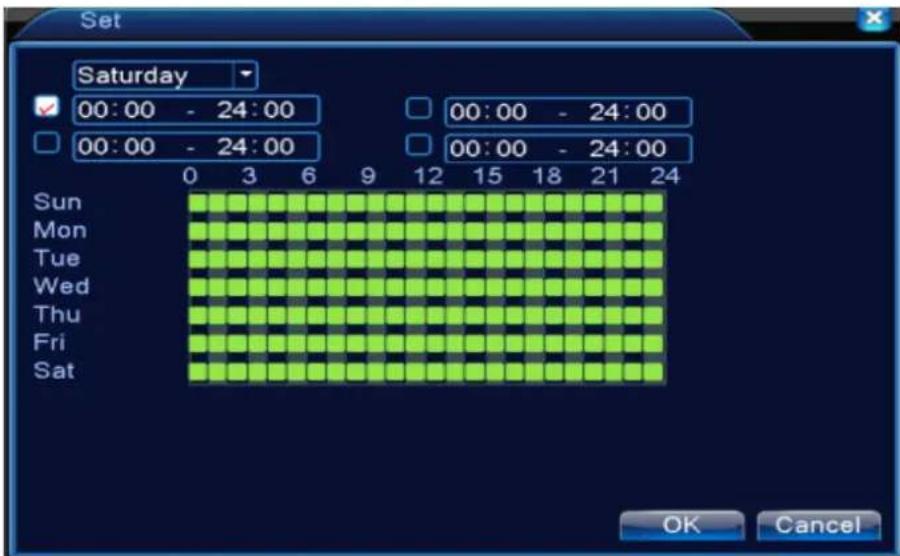
【Period】Trigger the motion detect signal in the set time section. You can set according to week or set uniformly. Each day is divided into four time sections.■ means the set valid.
text_image
Set Saturday 00:00 - 24:00 00:00 - 24:00 00:00 - 24:00 Sun Mon Tue Wed Thu Fri Sat OK CancelPicture 4.6 set the time section
【Interval】Only one alarm signal is turned on even there are several motion detect signals in the set interval.
【Alarm output】Start the external equipment of corresponding linkage alarm when the motion detect alarm is turned on.
【Delay】Delay a few moments and stop when the alarm state is turned off. The range is 10\~300 seconds.
【Record channel】Choose the recording channel (multiple option supportive). Trigger the video signal when the alarm is turned on.
Note: Set in the [recording setup] and perform the linkage recording. Start detecting video files in the corresponding time section.
【Tour】■ means that the selective channel is single window alternate patrol preview. The interval is set in the [Main Menu] > [System] > [Tour].
【PTZ Activation】Set the PTZ activation when the alarm is turned on.
*Hybrid mode, PTZ link to the related PTZ information of analog channel, While digital channel model, the PTZ is link to the related PTZ information on the remote device connected.
Note: to link PTZ, need go [Shortcut menu]->[PTZ control] to set preset point, cruise between points & interval time, etc.
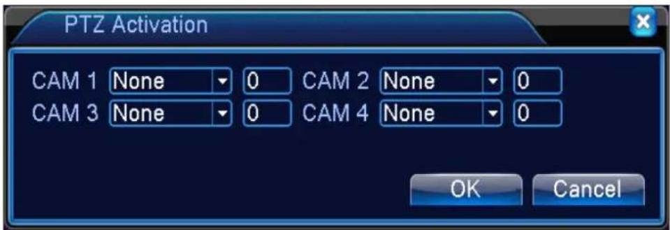
text_image
PTZ Activation CAM 1 None 0 CAM 2 None 0 CAM 3 None 0 CAM 4 None 0 OK CancelPicture 4.7 PTZ Activation under hybrid mode
【Delay】When alarm is over, recording will last some seconds(10\~300sec), then stop.
【Show message】Pop the alarm information dialog box in the local host computer screen.
【Send EMAIL】■ means sending an email to user when the alarm is turned on.
Note: Set in the [NetService] and send email.
【FTP upload】to tick it, the video & picture of related record channel & snapshot channel will be uploaded to assigned position.
Note: FTP upload need be set at [Netservice]
【Buzz】When alarm happens, device will come out with buzz.
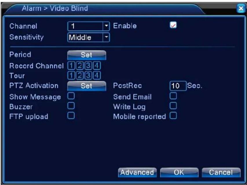
4.3.2 Video Blind
When the video image is influenced by the environment such as bad brightness or reaching the set sensitivity parameter, the camera mask function is turned on and the linkage function is turned on.
*Same as motion detect function, video blind is different between Hybrid mode & Full digital mode:
Digital channel: not only to enable video blind function at local side, but also to enable the remote device that was connected. when remote device with video blind, local side will start alarm recording, otherwise this function is not enable.
Hybrid mode: only need to enable video loss function at local side.
Note: "Advanced" button is the same as right click.
text_image
Alarm > Video Blind Channel 1 Enable ✓ Sensitivity Middle Period Set Record Channel 1 2 3 4 Tour 1 2 3 4 PTZ Activation Set PostRec 10 Sec. Show Message □ Send Email □ Buzzer □ Write Log □ FTP upload □ Mobile reported □ Advanced OK CancelPic 4.8 Video blind
Set method: refer to chapter 4.3.1. Motion detect
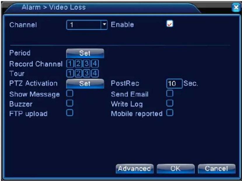
4.3.3 Video Loss
When the equipment can not obtain the channel video signal, the video loss alarm is turned on and the linkage function is turned on.
*Same as motion detect function, video loss is different between Hybrid mode & Full digital mode:
Digital channel: not only to enable video loss function at local side, but also to enable the remote device that was connected. when remote device with video loss, local side will start alarm recording, otherwise this function is not enable.
Hybrid mode: only need to enable video loss function at local side.
Note: "Advanced" button is the same as right click.
text_image
Alarm > Video Loss Channel 1 Enable Period Set Record Channel 1 2 3 4 Tour 1 2 3 4 PTZ Activation Set PostRec 10 Sec. Show Message □ Send Email □ Buzzer □ Write Log □ FTP upload □ Mobile reported □ Advanced OK CancelPic 4.9 Video loss
Set method: refer to chapter 4.3.1. Motion detect
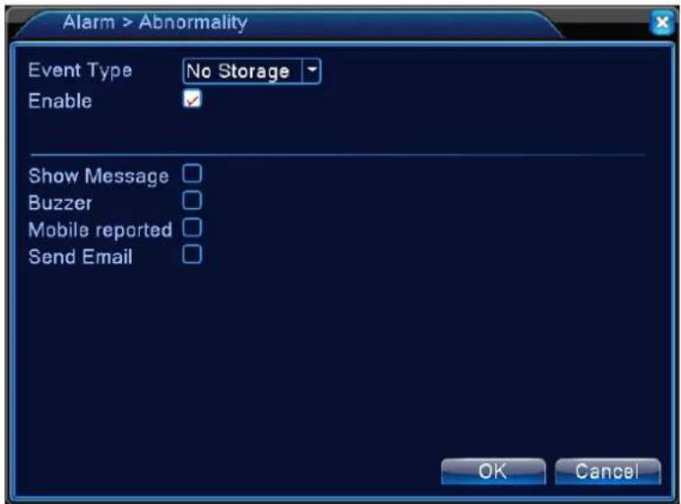
4.3.4 Abnormal
Analysing and inspecting current software and hardware of the device: When some abnormal events happen, the device will make a relative answer such as show message and buzzer.
text_image
Alarm > Abnormality Event Type No Storage Enable Show Message □ Buzzer □ Mobile reported □ Send Email □ OK CancelPicture 4.11 Abnormal

text_image
No Disk Disk Error Disk No Space Net Disconnection IP Conflict【Event Type】selecting abnormality you want to inspect
【Enable】 Select it to make sure abnormal function workable
【Show message】 Automatically alarm cue dialog box come out of the main screen
【Buzzer】 Device will have one long nosie "di" while alarm is happening
4.4 System setup
Set the system parameters such as General, Encode(under Hybrid/full analog mode)、Network, Net service、GUI display、PTZ configure/RS485 device、RS232、Tour setup、Spot and digital。
4.4.1 General
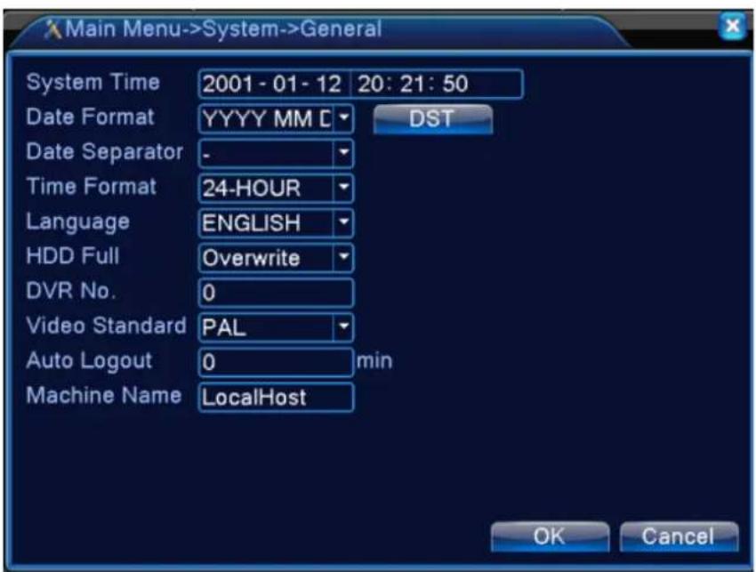
text_image
Main Menu->System->General System Time 2001 - 01 - 12 20: 21: 50 Date Format YYYY MM C DST Date Separator - Time Format 24-HOUR Language ENGLISH HDD Full Overwrite DVR No. 0 Video Standard PAL Auto Logout 0 min Machine Name LocalHost OK CancelPicture 4.17 General setup
【System time】Set the system data and time.
【Date format】Choose the data format: YMD, MDY, DMY.
【Date Separator】Choose list separator of the data format.
【Time Format】Choose time format: 24-hour or 12-hour.
【Language】support 29 language at present: Arabic, Czech, English, Finnish, Greek, Indonesian, Italian, Japanese, Portuguese, Russian, Thai, T-Chin
ese,S-Chinese,Turkish,Brazilian,Bulgarian,Farsi,French,German,Hebrew,Hungarian,Polish,Romanian,Spanish,Swedish,Vietnamese
【HDD full】Choose stop record: Stop recording when the hard disk is full.
Choose overwrite: Cover the earliest recording files and continue recording when the hard disk is full.
【DVR No.】Only when the address button in the remote controller and the corresponding DVR number is matched, the remote operation is valid.
【Video Standard】PAL or NTSC.
【Auto Logout】Set the latency time in 0-60. 0 means no latency time.
【Machine Name】Can setting the device's name.
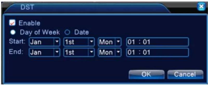
【DST】Choose the summer time option and pop the dialog box as followed.
text_image
DST Enable Day of Week Date Start: Jan 1st Mon 01 : 01 End: Jan 1st Mon 01 : 01 OK CancelPicture 4.18 DST (week)

text_image
DST Enable Day of Week Date Start: 2001 - 01 - 01 01: 01 End: 2001 - 01 - 01 01: 01 OK CancelPicture 4.19 DST (date)
4.4.2 Encode setup
*only 6000 series and HVR (other products only have analog channel) under Hybrid mode/full analog mode, it has encode setup function, encode settings is for analog channel only.
Set the video/audio code parameter: video file, remote monitoring and so on. Set every main stream parameter in the left part, and set the extra stream parameter in the right part.
Note: extra stream introduces video compression technique which was applying for multi-channel
playback simultaneously, Dial-up multi-channel real-time monitor under poor bandwidth, or mobile monitor and so on.
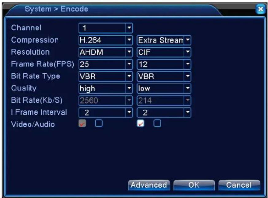
text_image
System > Encode Channel 1 Compression H.264 Extra Stream Resolution AHDM CIF Frame Rate(FPS) 25 12 Bit Rate Type VBR VBR Quality high low Bit Rate(Kb/S) 2560 214 I Frame Interval 2 2 Video/Audio Advanced OK CancelPicture 4.20 Encode setup
Independent channel code setting
【Channel】Choose the channel number.
【Compression】Standard H.264 main profile.
【Resolution】Resolution type: AHDM/AHDL/D1/CIF/QCIF.
【Frame Rate】P:1 frame/s\~25 frame/s; N: 1 frame/s\~30 frame/s
【Bit Rate Type】You can choose limited code stream or variable code stream. When you choose the variable code stream there are six image quality options. under the limited code stream, you can choose the code stream manually;
【Bit Rate】Set the code stream value to modify the image quality. The larger code stream value the better image quality.
1080P(1024\~8192kbsp) AHDM/720P(1024\~4096kbps) AHDL/960H(869\~4096kbps) D1
(512\~2560kbps) HD1 (384\~2048kbps) CIF (64\~1024kbps), QCIF(64\~512kbps)
【Frame Interval】can choose the range 2\~12s
【Video/Audio】When the icons are all in reverse displayed, the video file is video and audio multiplex stream.
Extra stream Settings
【Extra stream】is used for client side monitoring & mobile monitoring.
【Channel title】select channel title and then to choose whether need enable video & audio. The resolution, frame rate, bit rate type settings is the same as main stream.
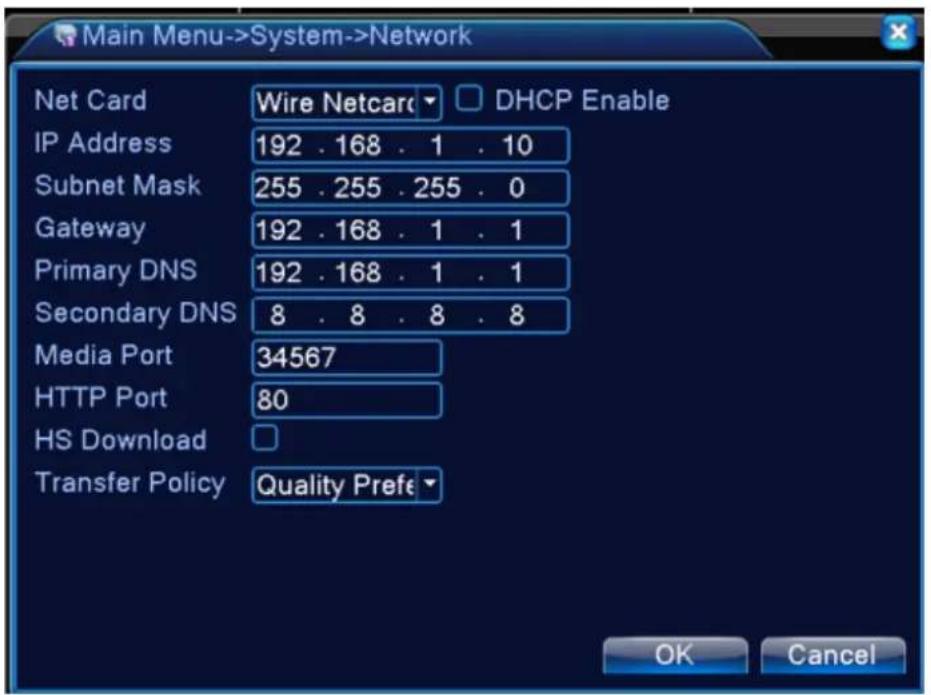
4.4.3 Network setup
text_image
Main Menu->System->Network Net Card Wire Netcard DHCP Enable IP Address 192 . 168 . 1 . 10 Subnet Mask 255 . 255 . 255 . 0 Gateway 192 . 168 . 1 . 1 Primary DNS 192 . 168 . 1 . 1 Secondary DNS 8 . 8 . 8 . 8 Media Port 34567 HTTP Port 80 HS Download Transfer Policy Quality Prefe OK CancelPicture4.21 Network
【Net Card】You can choose cable network card or wireless network card.
【DHCP Enable】Obtain IP address automatically(not suggested)
Note: DHCP server is preinstalled.
【IP address】Set the IP address. Default: 192.168.1.10.
【Subnet mask】Set the subnet mask code. Default: 255.255.255.0.
【Gateway】Set the default gateway. Default: 192.168.1.1.
【DNS setup】Domain Name Server. It translates the domain name into IP address. The IP address is offered by network provider. The address must be set and reboot then it works.
【Media port】Default: 34567.
【HTTP port】Default: 80.
【HS Download】
【Transfer Policy】There are three strategies: self-adaption, image quality precedence and fluency precedence. The code stream will adjust according to the setup. Self-adaption is the tradeoff between the image quality precedence and fluency precedence. Fluency precedence and self-adaption are
valid only when the assistant code stream is turned on. Otherwise image quality precedence is valid.
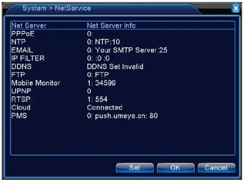
4.4.4 NetService
Choose the network service option and click the set button to configure the advanced network functions or double click the service button to configure the parameters.
text_image
System > NetService Net Server Net Server Info PPPoE 0: NTP 0: NTP:10 EMAIL 0: Your SMTP Server:25 IP FILTER 0: :0 :0 DDNS DDNS Set Invalid FTP 0: FTP Mobile Monitor 1: 34599 UPNP 0 RTSP 1: 554 Cloud Connected PMS 0: push.umeye.cn: 80 Set OK CancelPicture 4.22 NetService
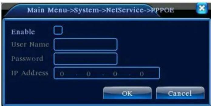
【PPPoE setup】
text_image
Main Menu->System->NetService->PPPOE Enable User Name Password IP Address 0 0 0 0 OK CancelPicture4.23 PPPOE
Enable: Reverse■ means choose, setting can become effective.
Input the user name and password that ISP (Internet service provider) provides. After saving it reboot up your system. Then the DVR will build a network connection based on PPPoE. The IP address will change into dynamic IP address after above operation is well done.
Operation: After PPPoE dialing successfully look up the IP address in the [IP address] and obtain the current IP address. Then use this IP address to visit the DVR through user port.
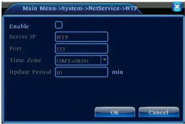
【NTP setup】
text_image
Main Menu->System->NetService->NTP Enable Server IP NTP Port 123 Time Zone GMT+08:00 Update Period 10 min OK CancelPicture 4.24 NTP
The NTP server must be installed in the PC.
Enable: Reverse■mean choose, setting can become effective.
Host computer IP: Input the IP address installed NTP server.
Port:Default: 123. You can set the port according to NTP server.
Time zone: London GMT+0 Berlin GMT +1 Cairo GMT +2 Moscow GMT +3 New Delhi GMT +5 Bangkok GMT +7 Hongkong Beijing GMT +8 Tokyo GMT +9 Sydney GMT +10 Hawaii GMT-10 Alaska GMT-9 Pacific time GMT-8 American mountain time GMT-7 American mid time GMT-6 American eastern time GMT-5 Atlantic time GMT-4 Brazil GMT-3 Atlantic mid time GMT-2.
Update Period: The same with the NTP server check interval. Default: 10 minutes.
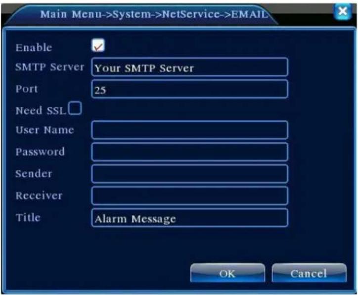
【EMAIL setup】
If the alarm is turned on or the alarm linkage photos are taken, send an email about the alarm information and the photos to appointed address.
text_image
Main Menu->System->NetService->EMAIL Enable ✓ SMTP Server Your SMTP Server Port 25 Need SSL User Name Password Sender Receiver Title Alarm Message OK CancelPicture 4.25 EMAIL
SMTP server: Email server address. It could be an IP address or domain name. Domain name can be translated only it is the correct DNS configuration.
Port: Email server port number.
SSL: Decide whether using Secure Socket Layer protocol to login.
User Name: Apply the email server user name.
Password: Input the password corresponding to the user.
Sender:Set the email sender address.
Receiver: Send the email to appointed receivers when the alarm is turned on. You can set three receivers at most.
Title: You can set as you wish.
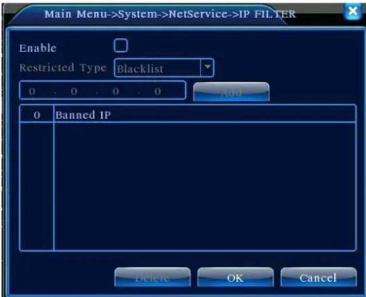
【IP Filter setup】
When choosing the white list, only the listed IP address can connect the DVR. The 64 IP addressed are supportive in the list.
When choosing the black list, the listed IP address can not connect the DVR. The 64 IP addressed are supportive in the list.
You can delete the set IP address by √ in the options.
Note: When the same IP address is in the white and black list at the same time, the black list precedence is higher.
text_image
Main Menu->System->NetService->IP FILTER Enable Restricted Type Blacklist 0 0 0 0 Add 0 Banned IP Delete OK CancelPicture 4.26 IP FILTER
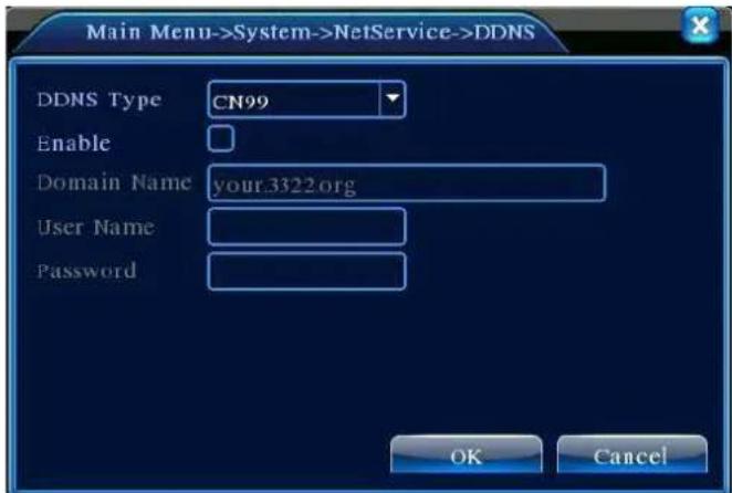
【DDNS】
text_image
Main Menu->System->NetService->DDNS DDNS Type CN99 Enable Domain Name your.3322.org User Name Password OK CancelPicture 4.27 DDNS setup
It is the abbreviation of dynamic domain name server.
Local domain name: Provide the domain name registered by DDNS.
User name: Provide the account registered by DDNS.
Password: Provide the password registered by DDNS.
When the DDNS is successfully configured and start, you can connect the domain name in the IE address column to visit.
Note: The DNS setup must be configured correctly in the network setup.
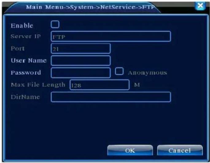
【FTP setup】
FTP is available only when alarm happens or alarm activates record and snapshot, it will upload related record and snapshot pictures to FTP server.
text_image
Main Menu->System->NetService->FTP Enable Server IP FTP Port 21 User Name Password Anonymous Max File Length 128 M DirName OK CancelPicture 4.28 FTP setup
【Enable】Click Enable, then all settings will be available
【Server IP】IP address for FTP server
【Port】Domain Port of FTP, default 21
【User Name】User name of FTP
【Password】Password of user
【Anonymous】: enable anonymous, no need setting user name and password
【Max File Length】Max length for upload files at every packed, default 128M
【Dir Name】: The directory of upload file.
Note: The user should be with authority to upload files.
To visit the device by mobile, please make a router mapping of this port and use CMS to monitor and operate it by protocol.

text_image
Main Menu->System->NetService->Mobil Enable Port 34599 OK CancelPicture 4.32 Mobile Monitor Setup
【Enable】 Select it to make sure abnormal function workable
【Port】 It's a port of mobile monitoring which you need to make a router mapping of if want to visit it by mobile
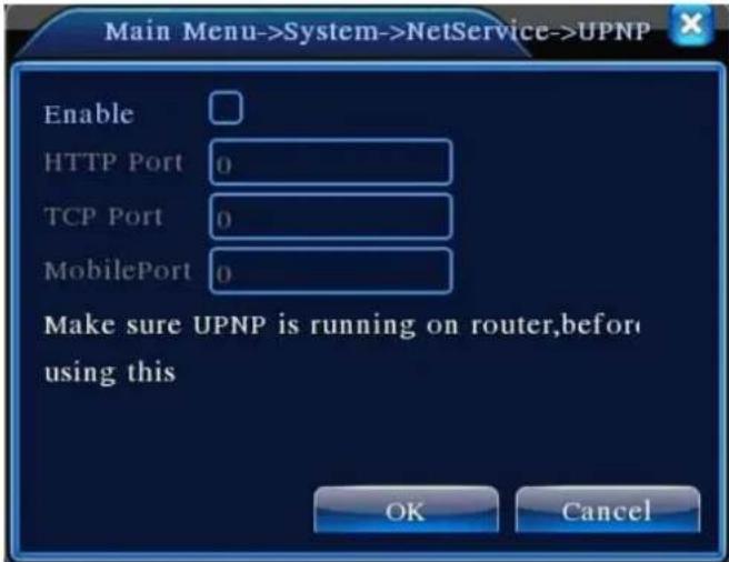
【UPNP】
UPNP protocol is to realize auto port forwarding on router, precondition of using this function is to make sure the UPNP function of router is enabled.
text_image
Main Menu->System->NetService->UPNP Enable HTTP Port 0 TCP Port 0 MobilePort 0 Make sure UPNP is running on router,before using this OK CancelPicture 4.33 UPNP
【Enable】Choose Enable to make sure all UPNP settings available
【HTTP】Route will automatically distribute HTTP port for the device, when IE viewing, it need this port
【TCP】Router will automatically distribute TCP port for the device, when monitoring via CMS, it need this port.
【Mobile Port】Router will automatically distribute Mobile Port for the device, when mobile monitor, it need this port.
【RTSP】
To do surveillance via cross-browser (Safari, Firefox, Google chrome) and VLC software. This function only for monitor but can not control the device.

text_image
RTSP Enable ✓ Port 554 OK CancelPic 4.35 RTSP setting
【Enable】: ■ means enable, tick it firstly before setting.
【Port】: the default port is 554
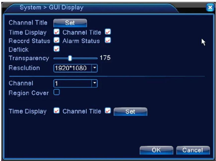
4.4.5 GUI Display
Configure the video output parameters including the front output mode and encode output mode.
Front output: In the local preview mode include: channel title, time display, channel display, record status, alarm status, transparency and region cover.
Encode output: In the network surveillance and video file mode include: channel title, time display, channel display, record status, alarm status, transparency and region cover.
text_image
System > GUI Display Channel Title Set Time Display ✓ Channel Title ✓ Record Status ✓ Alarm Status ✓ Deflick ✓ Transparency 175 Resolution 1920*1080 Channel 1 Region Cover Time Display ✓ Channel Title ✓ Set OK CancelPic 4.36 output mode
【Channel Title】Click the channel name modify button and enter the channel name menu. Modify the channel name. The 16 Chinese characters and 25 letters are supportive.
【Time Display】means the selective state. Display the system data and time in the surveillance window.
【Channel display】means the selective state. Display the system channel number in the surveillance window.
【Record Status】means the selective state. Display the system recording status in the surveillance window.
【Alarm Status】means the selective state. Display the system alarm status in the surveillance window.
【Transparency】Choose the background image transparency. The range is 128\~255.
【Resolution】set display resolution.
【Channel】Choose the set code output channel number.
【Region Cover】means the selective state. Click the cover area button and enter the corresponding channel window. You can cover the arbitrary using mouse. (Black region is for output)
【Time display】and 【Channel display】 set the display position of channel title and time title.
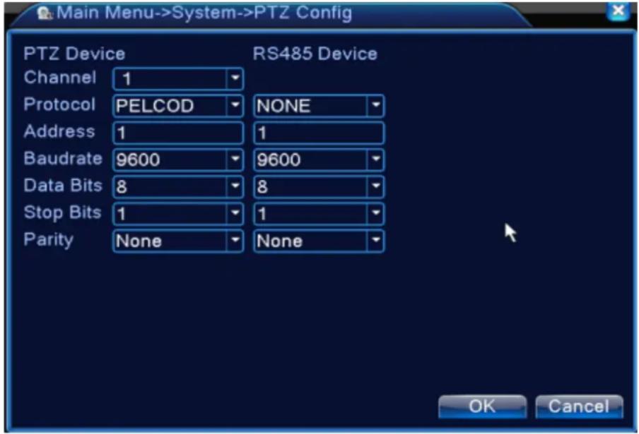
4.4.6 PTZ device /RS485 device
* when under hybrid mode/full digital mode, it shows with PTZ device and RS485 device,
text_image
Main Menu->System->PTZ Config PTZ Device Channel 1 Protocol PELCOD NONE Address 1 1 Baudrate 9600 9600 Data Bits 8 8 Stop Bits 1 1 Parity None None RS485 Device OK CancelPic 4.37 PTZ configure
【Channel】Choose the dome camera input channel.
【Protocol】Choose the corresponding dome protocol. (PELCOD as an example)
【Address】Set as the corresponding dome address. Default: 1. (Note: The address must be consistent with the dome address.)
【Baudrate】Choose the corresponding dome baud rate length. You can control the PTZ and vidicion. Default: 115200.
【Data bits】 Include 5-8 options. Default: 8.
【Stop bits】Include 2 options. Default: 1.
【Parity】Include odd check, even check, sign check, blank check. Default: void.
*When under full digital mode, it will show RS485 device.
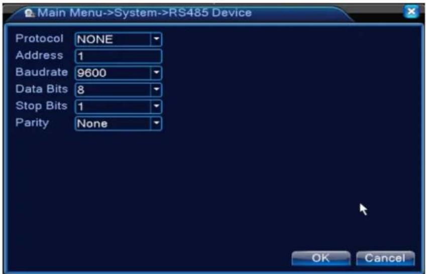
text_image
Main Menu->System->RS485 Device Protocol NONE Address 1 Baudrate 9600 Data Bits 8 Stop Bits 1 Parity None OK Cancel4.38 RS485 device
【Protocol】 choose related protocol of brand model;
【Address】set with corresponding address, default is 1;
【Baud rate】choose bard rate that related device use, default is 115200;
【Data bits】including 5-8 options, default is 8;
【Stop bits】including 2 options, default is 1;
【Parity】Include odd check, even check, sign check, blank check. Default: void.
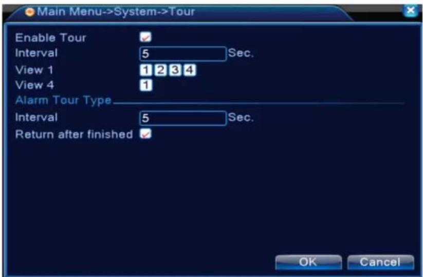
4.4.7 Tour
Set the patrol display. ■ means that the tour mode is enable. You can choose the single-view, four-view, six-view of single mode tour or hybrid mode tour.
text_image
Main Menu->System->Tour Enable Tour Interval 5 Sec. View 1 1 2 3 4 View 4 1 Alarm Tour Type Interval 5 Sec. Return after finished ✓ OK CancelPic 4.40 tour configure
【interval】Set the patrol switch interval. The set range is 5-120 seconds.
【alarm tour】set the interval to shift alarm tour, range is 5-120 seconds, choose return when alarm ends, when alarm link to tour, system will auto shift to six-view after alarm finished.
Remark: at preview mode, click upper right icon mean turn off).
/ can turn on / off tour ( mean turn on,
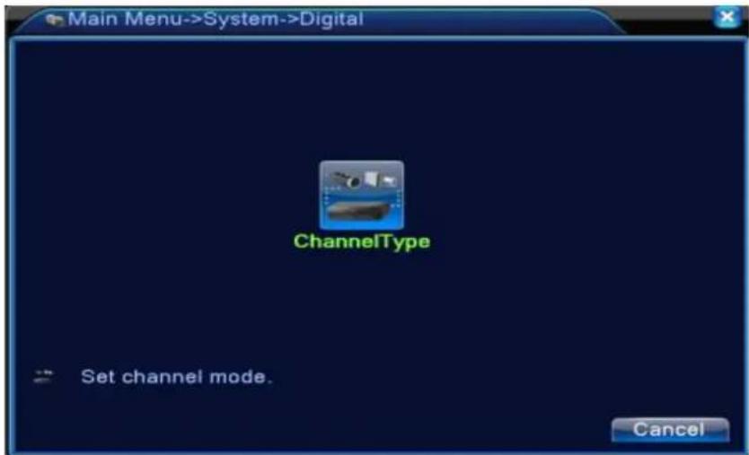
4.4.8 Channel manage
Digital manage including digital channel, channel status, and channel mode (Remark: there is only analog mode if device is under full analog mode):
text_image
Main Menu->System->Digital ChannelType Set channel mode. CancelChannel manage page under all analog(DVR) mode
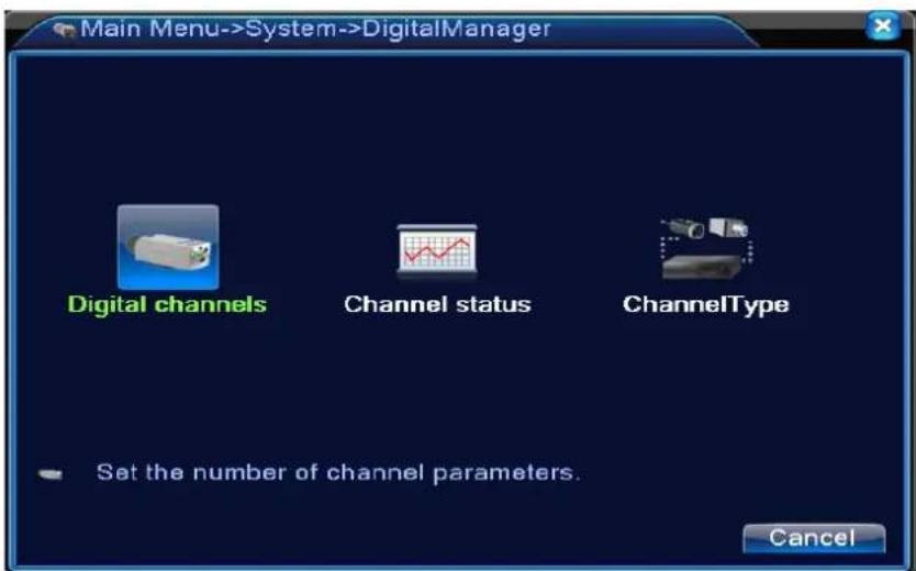
text_image
Main Menu->System->DigitalManager Digital channels Channel status ChannelType Set the number of channel parameters. CancelChannel manage page under Hybrid(HVR) mode / full digital(NVR) mode
Pic 4.42 channel manage interface
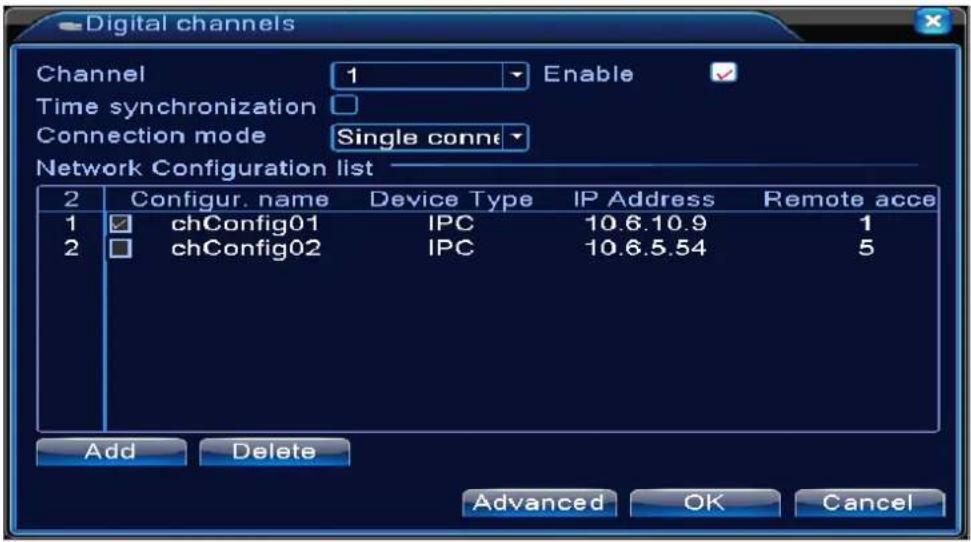
Digital channel:
text_image
Digital channels Channel 1 Enable Time synchronization □ Connection mode Single conn Network Configuration list 2 Configur. name Device Type IP Address Remote acce 1 chConfig01 IPC 10.6.10.9 1 2 chConfig02 IPC 10.6.5.54 5 Add Delete Advanced OK CancelSingle link page of digital channel
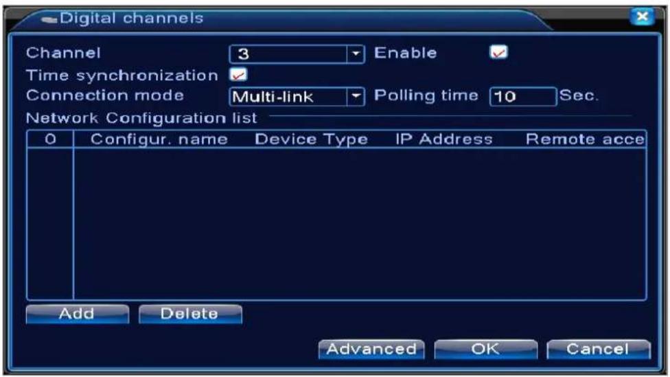
text_image
Digital channels Channel 3 Enable ✓ Time synchronization ✓ Connection mode Multi-link Polling time 10 Sec. Network Configuration list 0 Configur. name Device Type IP Address Remote acce Add Delete Advanced OK CancelMulti-linkage page of Digital channel
Pic 4.43 digital channel interface
【Channel】select channel title
【Enable】Open digital channel, tick enable, then can do related settings
【Time Synchronization】Tick it means the time of this channel and device is the same.
【Connection Mode】can be single connect or multi-ink, multi-link modes can connect to several devices, device will be tour displayed one by one, tour interval can be set, no less then 10s;
【Delete】If the user want to change device, select the existing device, click delete will be ok.
【Add】click add will come out below page to add new device
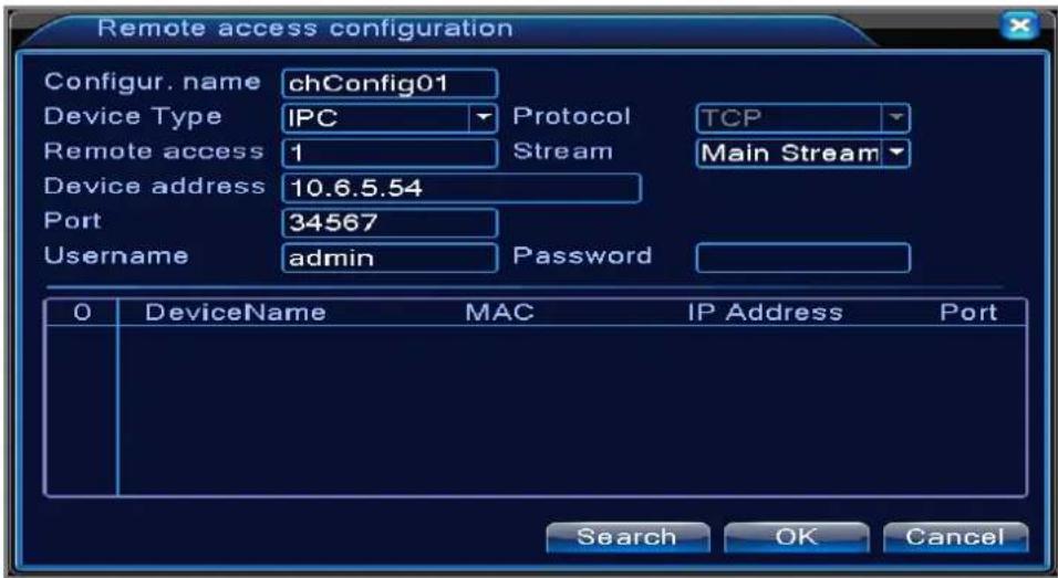
text_image
Remote access configuration Configur. name chConfig01 Device Type IPC Protocol TCP Remote access 1 Stream Main Stream Device address 10.6.5.54 Port 34567 Username admin Password 0 DeviceName MAC IP Address Port Search OK CancelPic 4.44 remote channel configure page
【Configure Name】device is with default configure title, user can revise it if necessary;
【Device Type】3 types: IPC、DVR、HVR, user can choose as what you like, default is IPC;
【Protocol】Default is TCP
【Remote channel】User can input remote channel title from the device that you want to connect remotely
【Stream】Default is main stream, do not support extra-stream at present;
【Device address】IP address of device.
【Port】Default is 34567
【User name】Default is admin
Remark: click 【search】will show all the devices that searched out, user can choose any of the device that you like.
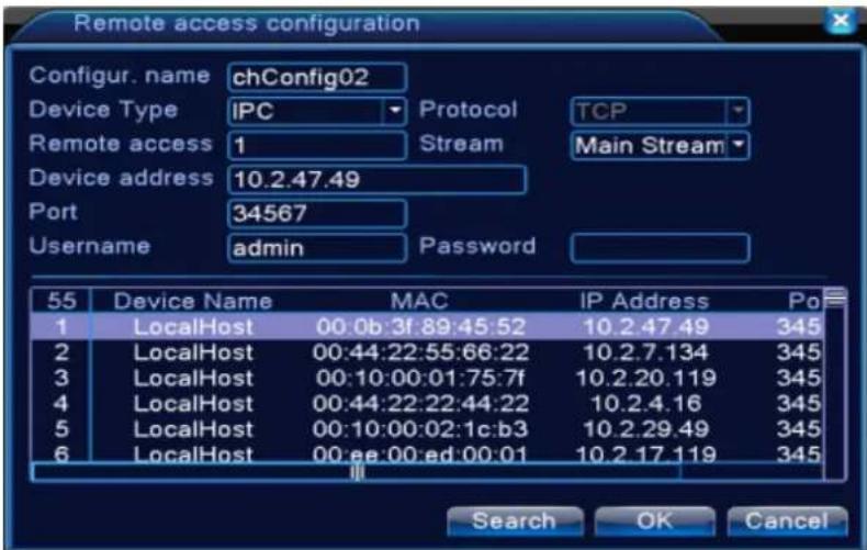
text_image
Remote access configuration Configur. name chConfig02 Device Type IPC Protocol TCP Remote access 1 Stream Main Stream Device address 10.2.47.49 Port 34567 Username admin Password 55 Device Name MAC IP Address Po 1 LocalHost 00:0b:3f:89:45:52 10.2.47.49 345 2 LocalHost 00:44:22:55:66:22 10.2.7.134 345 3 LocalHost 00:10:00:01:75:7f 10.2.20.119 345 4 LocalHost 00:44:22:22:44:22 10.2.4.16 345 5 LocalHost 00:10:00:02:1c:b3 10.2.29.49 345 6 LocalHost 00:ee:00:ed:00:01 10.2.17.119 345 Search OK CancelPic 4.45 the device list searched under remote channel setting
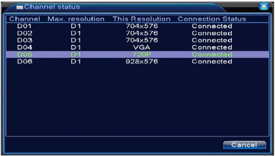
Channel Status:
channel status is to show the status of all the digital channel When there is what existing, status including Max Resolution, This Resolution, Connection Status.
For example: The channel status for 4+2 mode is as below:
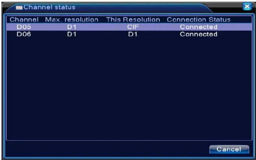
text_image
Channel status Channel Max. resolution This Resolution Connection Status D05 D1 CIF Connected D06 D1 D1 Connected CancelWhen a channel is added with device but it is not enable, you will see as below:
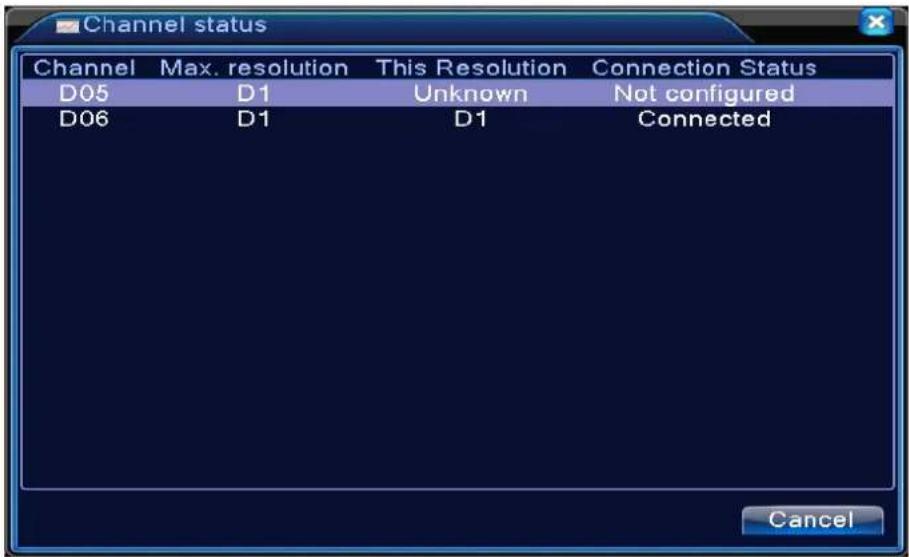
text_image
Channel status Channel Max. resolution This Resolution Connection Status D05 D1 Unknown Not configured D06 D1 D1 Connected CancelChannel status interface under full digital(NVR) mode (One of the channel without device)
text_image
Channel status Channel Max. resolution This Resolution Connection Status D01 D1 704x576 Connected D02 D1 704x576 Connected D03 D1 704x576 Connected D04 D1 VGA Connected D05 D1 720P Connected D06 D1 928x576 Connected CancelRemark: when the current resolution is over the max resolution that the channel supported, then a red "X" will be shown on the preview image, for example: Under full digital channel mode, Max resolution of channel 3 is D1, if it was connected to a device with resolution over D1 (such as 960H), you will see below pic:

text_image
x D03Channel mode:
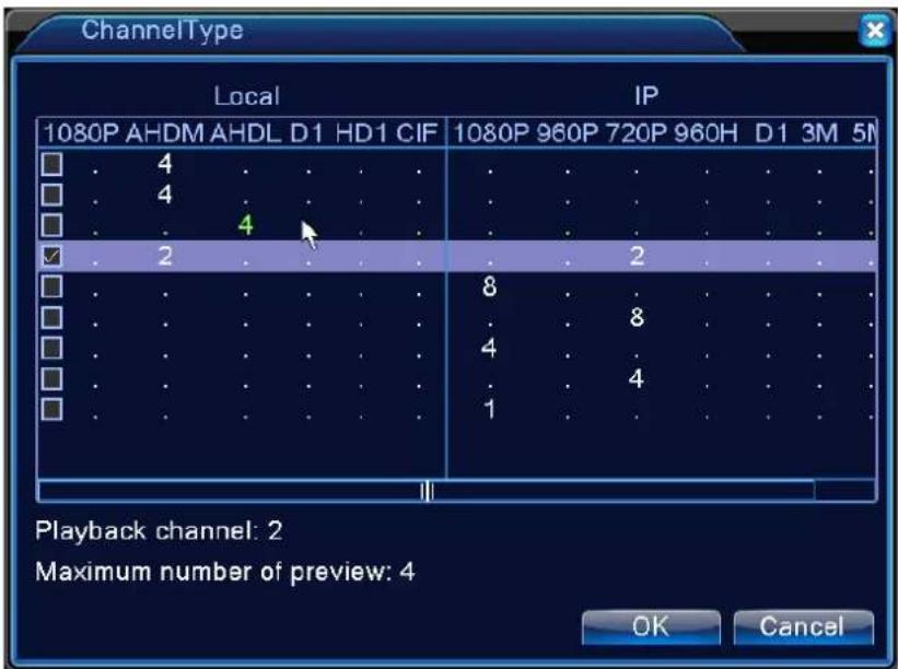
text_image
ChannelType Local IP 1080P AHDM AHDL D1 HD1 CIF 1080P 960P 720P 960H D1 3M 5N 4 4 4 2 8 8 4 4 1 Playback channel: 2 Maximum number of preview: 4 OK CancelRemark: this series of product with full analog channel mode, hybrid mode and full digital mode, and different model with different channel mode, user can shift the mode freely if necessary.
4.5 Advanced
Manage tools menu including: HDD manage, account manage, online user, output adjust, auto maintain, upgrade.
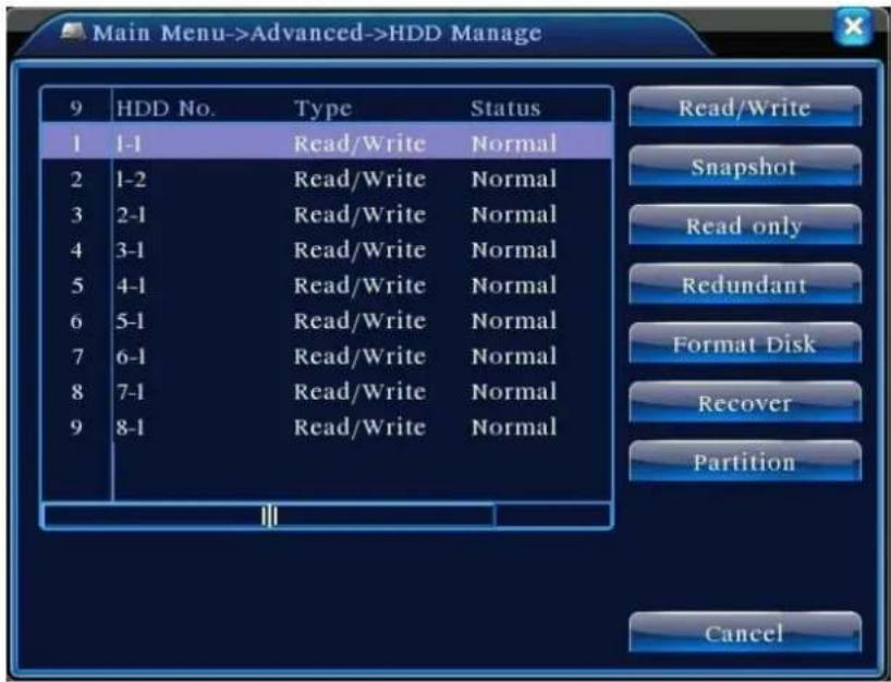
4.5.1 HDD Manage
Configure and manage the hard disk. The menu displays current hard disk information: hard disk number, input port, type, status and overall capability. The operation include: setup the write-read disk, read-only disk, redundant disk, hard disk format, resume default. Choose the hard disk and click the right function button to execute.
Note: Read/Write Disk: The equipment can write or read data.
Read-only Disk: The equipment can read data but can not write data.
Redundant Disk: Double backup the video files in the write-read disk.
text_image
Main Menu->Advanced->HDD Manage 9 HDD No. Type Status 1 1-1 Read/Write Normal 2 1-2 Read/Write Normal 3 2-1 Read/Write Normal 4 3-1 Read/Write Normal 5 4-1 Read/Write Normal 6 5-1 Read/Write Normal 7 6-1 Read/Write Normal 8 7-1 Read/Write Normal 9 8-1 Read/Write Normal Read/Write Snapshot Read only Redundant Format Disk Recover Partition CancelPic 4.46 HDD manage
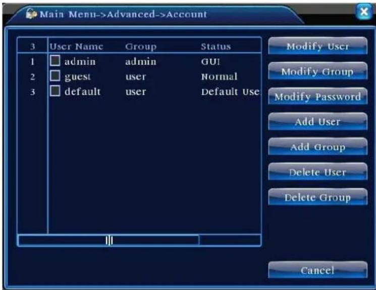
4.5.2 Account
Manage the user purview.
Note: 1. The character length is 8 bytes at most for the following user and user team name. The blank ahead or behind the character string is invalid. The middle blank in the character string is valid. Legal characters include: letter, number, underline, subtraction sign, dot.
- There is no limit in the user and user group. You can add or delete the user group according to user definition. The factory setup include: user\admin. You can set the team as you wish. The user can appoint the purview in the group.
- The user management include: group/ user. The group and user name can not be the same. Each user only belongs to one group.
text_image
Main Menu->Advanced->Account 3 User Name Group Status 1 admin admin GUI 2 guest user Normal 3 default user Default Use Modify User Modify Group Modify Password Add User Add Group Delete User Delete Group CancelPic 4.47 account management
【Modify User】Modify the existed user attribute.
【Modify Group】Modify the existed team attribute.
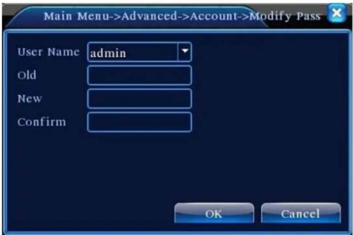
【Modify Password】Modify the user password. You can set 1-6 bit password. The blank ahead or behind the char string is invalid. The middle blank in the char string is valid.
Note: The user who possess the user control purview can modify his/her own or other users password
text_image
Main Menu->Advanced->Account->Modify Pass User Name admin Old New Confirm OK CancelPic 4.48 modify password
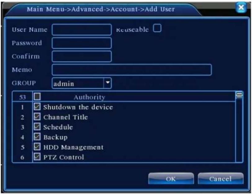
【Add user】Add a user in the group and set the user purview. Enter the menu interface and input the user name and password. Choose the team and choose whether cover using the user. Cover using means that the account can be used by multiple users at the same time.
Once choose the team the user purview is the subclass of the team.
We recommend that the common user's purview is lower than the advanced user.
text_image
Main Menu->Advanced->Account->Add User User Name Keuseable Password Confirm Memo GROUP admin 53 Authority 1 Shutdown the device 2 Channel Title 3 Schedule 4 Backup 5 HDD Management 6 PTZ Control OK CancelPic 4.49 Add User
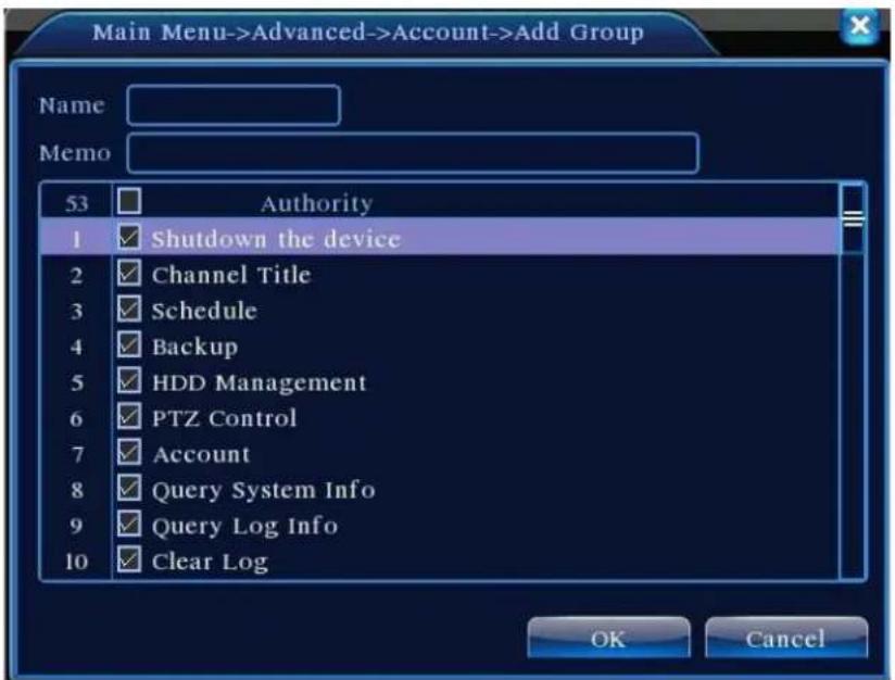
【Add Group】Add a user group and set the purview. There are 33 different purviews: shut down the equipment, real time surveillance, playback, record setting, video backup and so on.
text_image
Main Menu->Advanced->Account->Add Group Name Memo 53 Authority 1 Shutdown the device 2 Channel Title 3 Schedule 4 Backup 5 HDD Management 6 PTZ Control 7 Account 8 Query System Info 9 Query Log Info 10 Clear Log OK CancelPic 4.50 add group
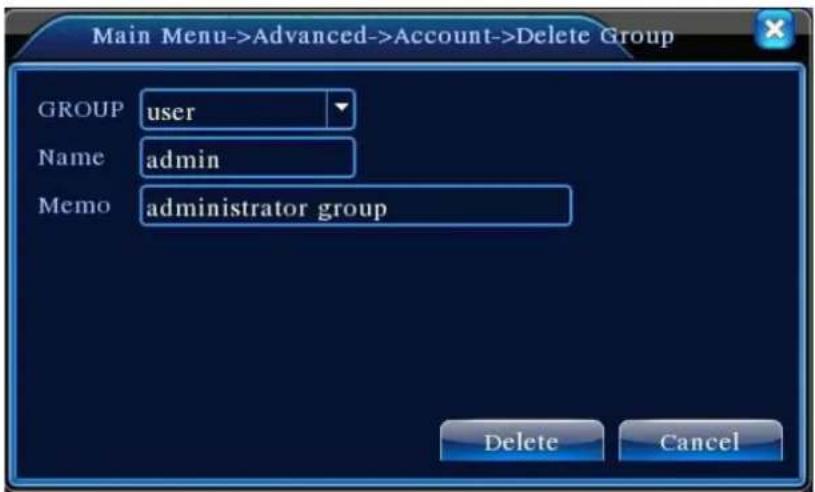
【Delete User】 Delete the current user. Choose the user and click delete user button.
【Delete Group】Delete the current group. Choose the group and click delete group button.
text_image
Main Menu->Advanced->Account->Delete Group GROUP user Name admin Memo administrator group Delete CancelPic 4.51 Delete Group
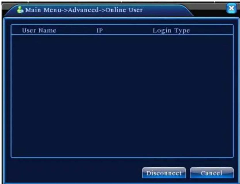
4.5.3 Online user
To check the information of network user that connected with local device, also can tick the selected user to break up connection, (make √ at the box), then the user will be frozen after connection stopped, and will not log in until device reboot.
text_image
Main Menu->Advanced->Online User User Name IP Login Type Disconnect CancelPic 4.52 online user
4.5.4 Output adjust
Refer to chapter 3.5.7 .
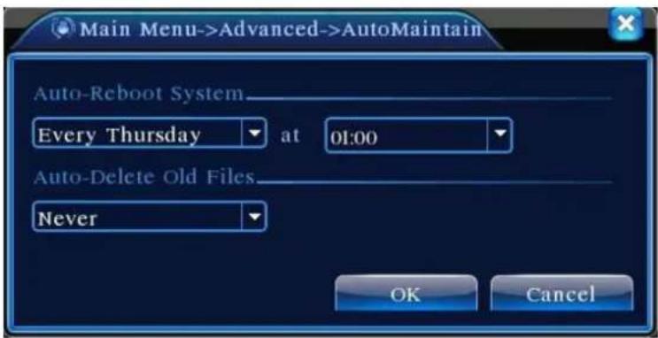
4.5.5 Auto Maintain
The user can set the time to auto reboot and auto delete file.
text_image
Main Menu->Advanced->AutoMaintain Auto-Reboot System Every Thursday at 01:00 Auto-Delete Old Files Never OK CancelPicture 4.39 Auto maintain
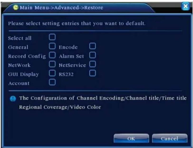
4.5.6 Restore
The system restore to the default. You can choose the items according to the menu.
text_image
Main Menu->Advanced->Restore Please select setting entries that you want to default. Select all General Record Config NetWork GUI Display Account Encode Alarm Set NetService RS232 The Configuration of Channel Encoding/Channel title/Time title Regional Coverage/Video Color OK CancelPic 4.54 restore to default
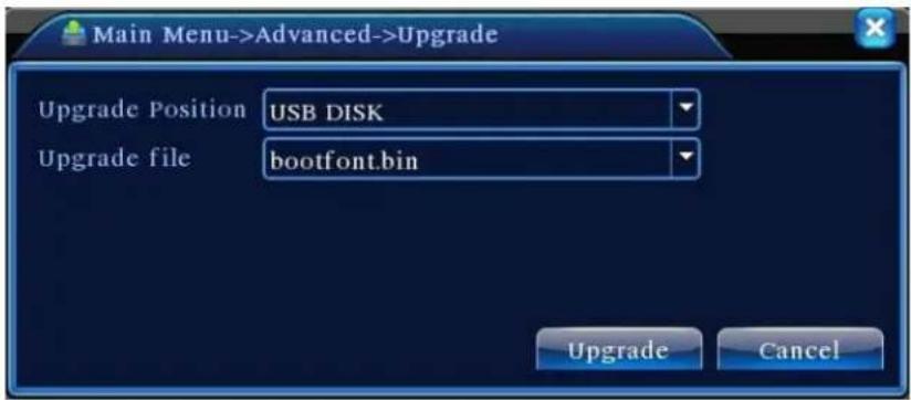
4.5.7 Upgrade
text_image
Main Menu->Advanced->Upgrade Upgrade Position USB DISK Upgrade file bootfont.bin Upgrade CancelPic 4.55 Upgrade
【Upgrade file】 choose the upgrade file.
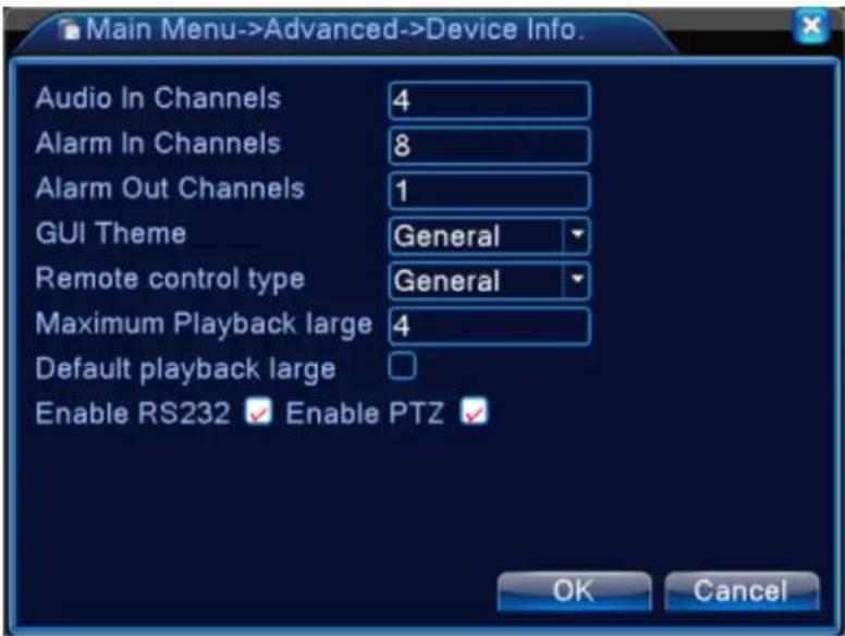
4.5.8 Device Info
Provide device interface info like audio in, alarm in/out to be conveniently used for user.
text_image
Main Menu->Advanced->Device Info. Audio In Channels 4 Alarm In Channels 8 Alarm Out Channels 1 GUI Theme General Remote control type General Maximum Playback large 4 Default playback large Enable RS232 ✓ Enable PTZ ✓ OK CancelPic 4.56 device info
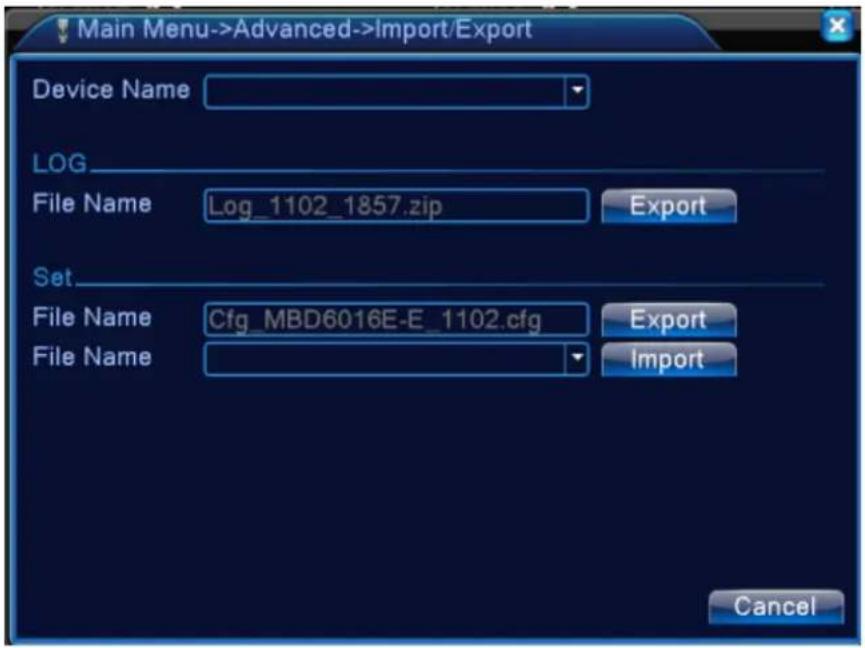
4.5.9 Import / Export
Users can export the log info and the configure file from device to connected flash stick, and also can import related configure file from flash stick to settings, which greatly bring convenience to the customers.
text_image
Main Menu->Advanced->Import/Export Device Name LOG File Name Log_1102_1857.zip Export Set File Name Cfg_MBD6016E-E_1102.cfg Export File Name Import Cancel4.57 Import / Export interface
4.6 Info
Display the hard disk information, including HDD info, code stream statistic, log info, version info
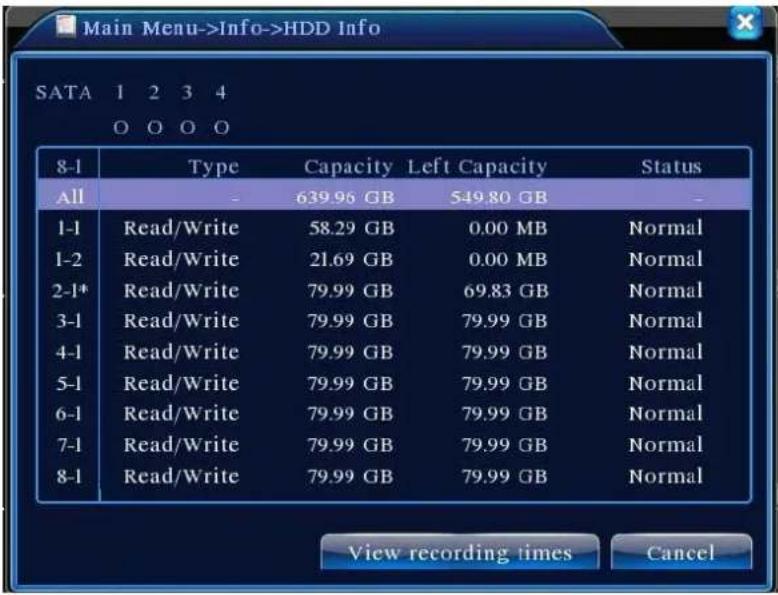
4.6.1 HDD info
Display the hard disk state: hard disk type, overall capability, residual capability, the recording time and so on.
text_image
SATA 1 2 3 4 O O O O 8-1 Type Capacity Left Capacity Status All - 639.96 GB 549.80 GB - 1-1 Read/Write 58.29 GB 0.00 MB Normal 1-2 Read/Write 21.69 GB 0.00 MB Normal 2-1* Read/Write 79.99 GB 69.83 GB Normal 3-1 Read/Write 79.99 GB 79.99 GB Normal 4-1 Read/Write 79.99 GB 79.99 GB Normal 5-1 Read/Write 79.99 GB 79.99 GB Normal 6-1 Read/Write 79.99 GB 79.99 GB Normal 7-1 Read/Write 79.99 GB 79.99 GB Normal 8-1 Read/Write 79.99 GB 79.99 GB Normal View recording times CancelPic 4.58 HDD info
Tips: ○ means that the hard disk is normal. X means that the hard disk is broken-down.- means that there is no hard disk. If the user need to change the damaged hard disk, you must shut down the DVR and take up all the damaged hard disks, then install a new one.
* behind serial number means the current working disk such as 1*. If the corresponding disk is damaged, the information will show “?”.
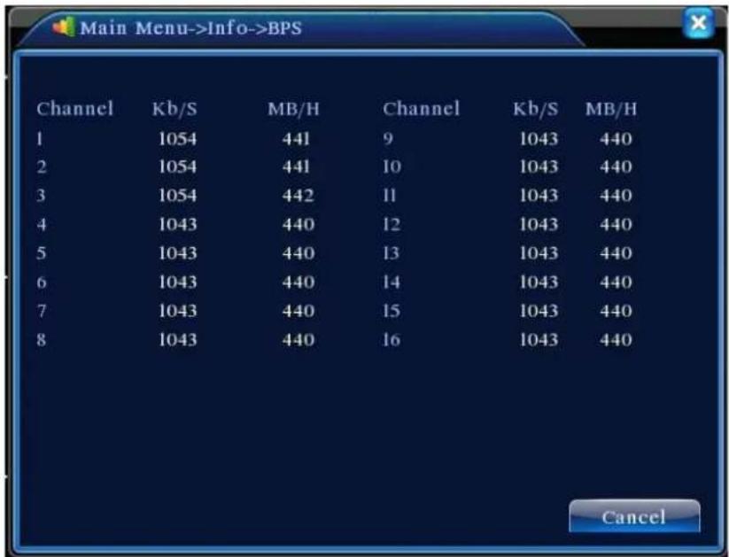
4.6.2 BPS
Display the code stream (Kb/S) and hard disk capability (MB/H) in real time. It displays as the wave sketch map.
text_image
Main Menu->Info->BPS Channel Kb/S MB/H Channel Kb/S MB/H 1 1054 441 9 1043 440 2 1054 441 10 1043 440 3 1054 442 11 1043 440 4 1043 440 12 1043 440 5 1043 440 13 1043 440 6 1043 440 14 1043 440 7 1043 440 15 1043 440 8 1043 440 16 1043 440 CancelPic 4.59 BPS
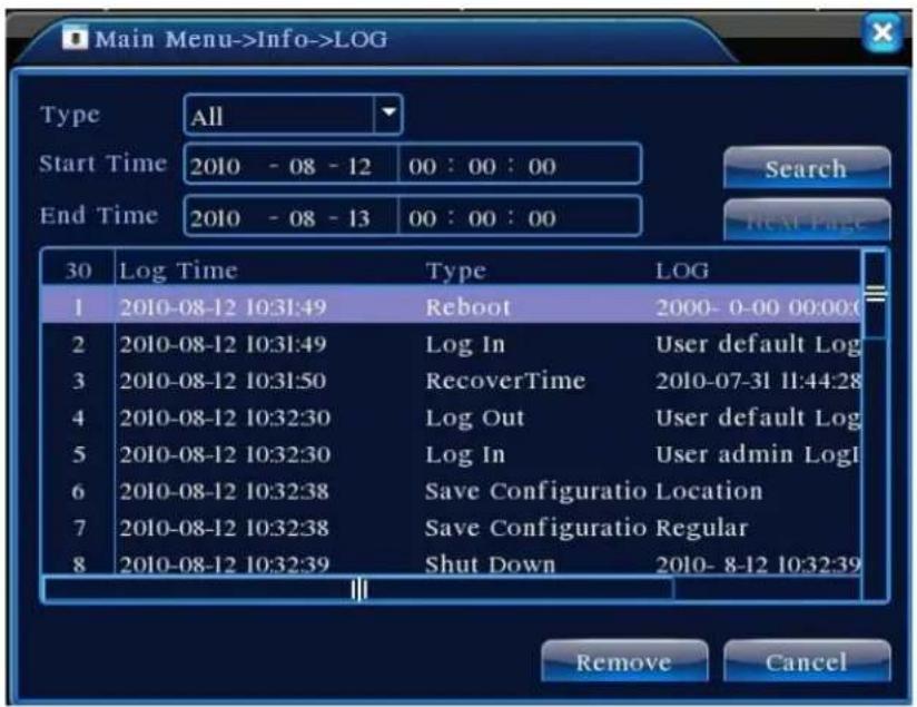
4.6.3 LOG
To search log information base on the set search mode.
Log information include: system operation, configuration operation, data management, alarm affair, recording operation, user management, file management and so on. Set the time section to look up and click the look up button. The log information will display as a list. (one page is 128 items) Press Page up or Page down button to look up and press delete button to clear all the log information.
text_image
Main Menu->Info->LOG Type All Start Time 2010 - 08 - 12 00 : 00 : 00 End Time 2010 - 08 - 13 00 : 00 : 00 30 Log Time Type LOG 1 2010-08-12 10:31:49 Reboot 2000- 0-00 00:00:0 2 2010-08-12 10:31:49 Log In User default Log 3 2010-08-12 10:31:50 RecoverTime 2010-07-31 11:44:28 4 2010-08-12 10:32:30 Log Out User default Log 5 2010-08-12 10:32:30 Log In User admin Log1 6 2010-08-12 10:32:38 Save Configuratio Location 7 2010-08-12 10:32:38 Save Configuratio Regular 8 2010-08-12 10:32:39 Shut Down 2010- 8-12 10:32:39 Remove CancelPic: 4.60 Log information
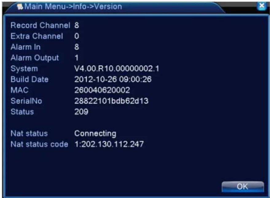
4.6.4 Version
Display the basic information such as hardware information, software version, issue date, serial number, NAT status and so on.
text_image
Record Channel 8 Extra Channel 0 Alarm In 8 Alarm Output 1 System V4.00.R10.00000002.1 Build Date 2012-10-26 09:00:26 MAC 260040620002 SerialNo 28822101bdb62d13 Status 209 Nat status Connecting Nat status code 1:202.130.112.247Pic 4.61 version information
4.7 Shut down system
Refer to chapter 3.5.8.
Chapter 5: Cloud Technology Basic Operation
5.1 Cloud technology monitor
Cloud technology make the device one step on net, greatly bring convenience for customer to monitor via wide area network, this technology is using the serial no to visit device.
*Remark: the device that using cloud technology should be in the WAN( Wide Area Network )firstly.
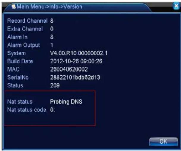
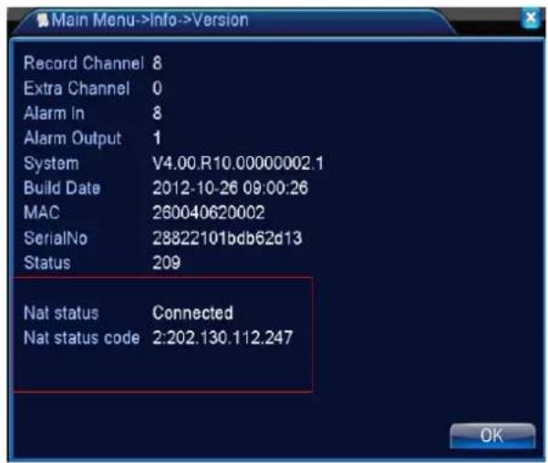
➢ Check the connecting status of cloud technology
Connect device to WAN firstly, then enter【Main menu】>【Info】>【Version】to check whether the device successfully connect to the cloud server or not.
text_image
Main Menu->Info->Version Record Channel 8 Extra Channel 0 Alarm In 8 Alarm Output 1 System V4.00.R10.00000002.1 Build Date 2012-10-26 09:00:26 MAC 260040620002 SerialNo 28822101bdb62d13 Status 209 Nat status Probing DNS Nat status code 0:Connect failed interface
text_image
Main Menu->Info->Version Record Channel 8 Extra Channel 0 Alarm In 8 Alarm Output 1 System V4.00.R10.00000002.1 Build Date 2012-10-26 09:00:26 MAC 260040620002 SerialNo 28822101bdb62d13 Status 209 Nat status Connected Nat status code 2:202.130.112.247successfully connect interface
Pic 5.1 cloud technology server connection status
Log in cloud server
Visit http://xmeye.net to see below log in page, it devided into two mode: by user and by device, user can base on their need to log in freely.
*Remark: to log in "by user", the user need to register at the first time.
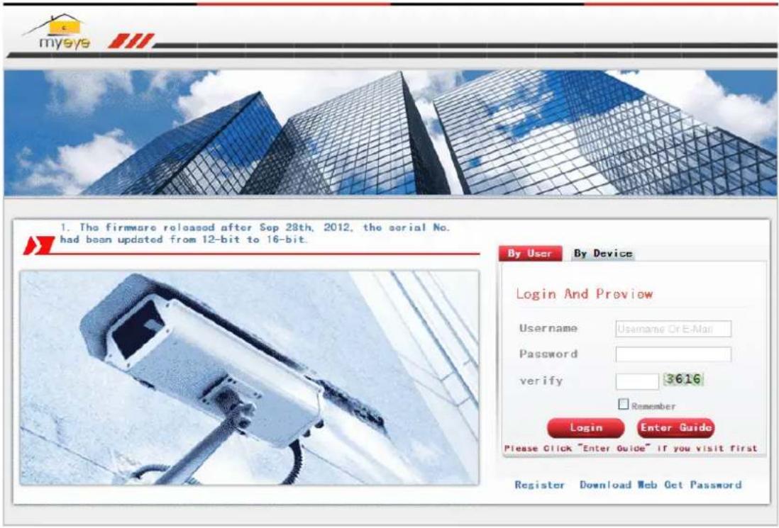
text_image
mysys 1. The firmware released after Sep 28th, 2012, the serial No. had been updated from 12-bit to 16-bit. By User By Device Login And Preview Username Username Or E-Mail Password verify 3616 Remember Login Enter Guide Please Click "Enter Guide" if you visit first Register Download Web Get PasswordLog in by user
Customer use their registered user name and password to log in, will see below interface
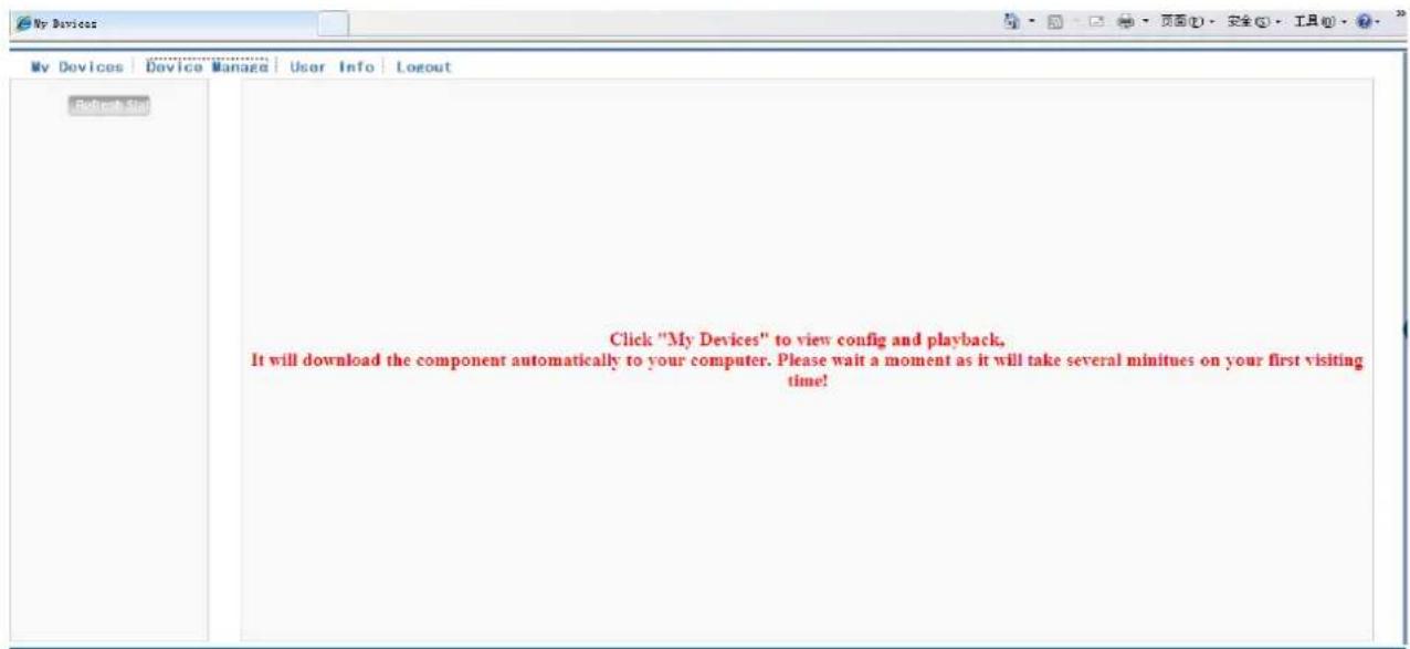
text_image
My Devices Device Manage | User Info | Logout Get out this Click "My Devices" to view config and playback. It will download the component automatically to your computer. Please wait a moment as it will take several minutes on your first visiting time!Pic 5.3 cloud technology operation interface
Device manage
Mainly use to add device, click "add" to add the serial number of device to be monitored.
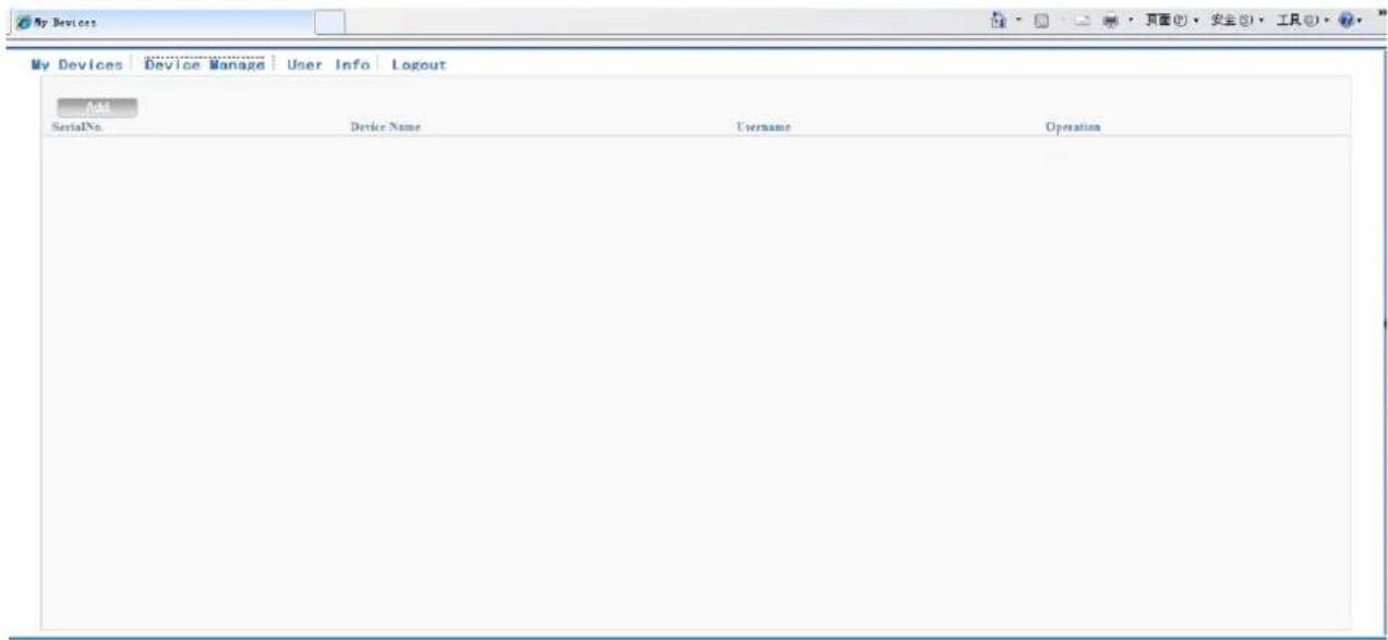
text_image
My Devices Device Manage | User Info | Logout Add SerialNo. Device Name Username OperationPic 5.4 device manage interface
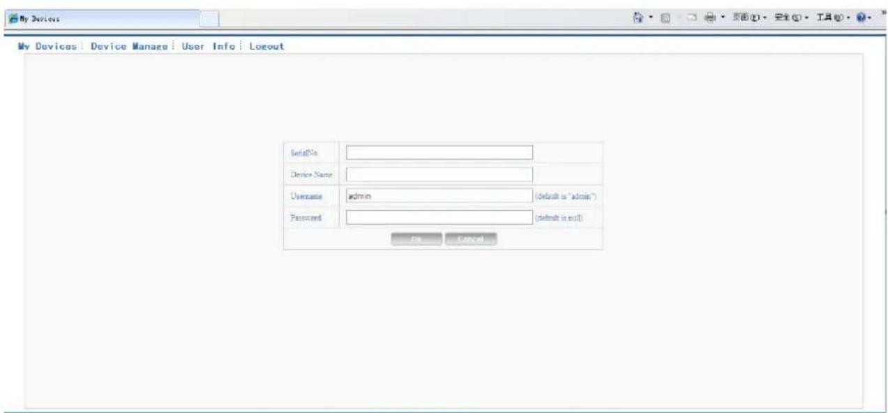
text_image
My Devices | Device Manage | User Info | Logout SerialNo: Device Name: Username admin (default is "admin") Password (default is null) OK CancelPic 5.5 add interface at device manage
*Remark: in pic 5.5, the user name means the user name of monitored device, password means the password of related user.
My Device
Mainly show all the added device here, click the on-line device name, can access to control this device accordingly.
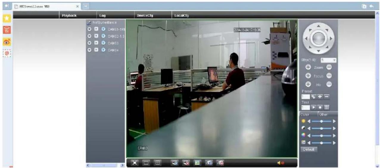
text_image
RXTS surveillance VR8 Playback Log DeviceCtrg LocalCtrg NetSurveillance CAME1-1M CAME2-1.1 CAME3 CAME4 2014-11-04 17:19:36 CAM03 CAM03Pic 5.6 monitor page - log in by user
*Remark: the icon of “✗” means offline, the device do not connect to server successfully.
Log in by device
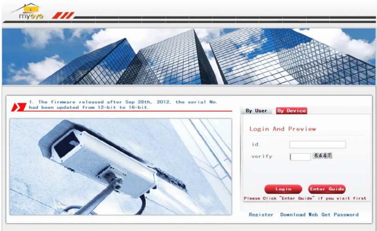
text_image
myeye 1. The firmware released after Sep 28th, 2012, the serial No. had been updated from 12-bit to 16-bit. By User By Device Login And Preview id verify 8447 Login Enter Guide Please Click "Enter Guide" if you visit first Register Download Web Get PasswordPic 5.7 interface of log in by device
Input the serial number of device and the verify code to monitor and control the device directly.
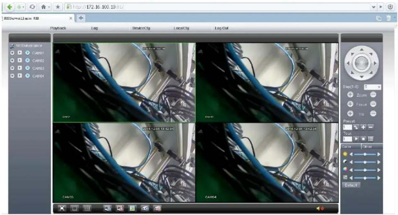
text_image
REISurveillance REI Playback Log DeviceCtg LocalCtg Log Out NetSurveillance CAM01 CAM02 CAM03 CAM04 CAM07 CAM08 2014-12-04 13:42:34 CAM09 CAM0A CAM0B CAM0C CAM0D Slow(1-8): 5 Zoom Focus Hig Preset: 1 Tour: 1 Color Other DefaultPic: 5.8 monitor page - log in by device
6 FAQ and maintenance
6.1 FAQ
If the problems are not listed, please contact the local service or call the HQ service. We are willing to offer the service.
1、The DVR can not boot up normally.
Possible reasons are as followed:
1 The power supply is not correct.
2 Switch power supply line is not in good connection.
3 Switch power supply is damaged.
4 The program updating is wrong.
5 The hard disk is damaged or the hard disk lines are broken.
6 The front panel is damaged.
7 The main board of the DVR is damaged.
2、The DVR reboots automatically or stops working after boot up a few minutes.
Possible reasons are as followed:
1 The input voltage is not stable or too low.
2 The hard disk is damaged or the hard disk lines are broken.
3 The power of the switch power supply is low.
4 Frontal video signal is not stable.
5 Bad heat radiator or too much dust or bad running circumstance for the DVR.
6 The hardware of the DVR is damaged.
3、System can not detect hard disk.
Possible reasons are as followed:
1 The hard disk power supply line is not connected.
2 The cables of the hard disk are damaged.
3 The hard disk is damaged.
4 The SATA port of main board is damaged.
4、There are no video outputs in single channel, multiple channels and all channels.
Possible reasons are as followed:
1 The program is not matched. Please update the program.
2 The image brightness is all 0. Please restore the default setup.
3 There is no video input signal or the signal is too weak.
4 The channel protection or the screen protection is set.
5 The hardware of the DVR is damaged.
5、Real-time image problems such as the image color or the brightness distortion.
Possible reasons are as followed:
1 When using the BNC output, the option between the N mode or PAL mode is wrong and the image becomes black and white.
2 The DVR is not matched the monitor impedance.
3 The video transmission distance is too far or the loss of the video transmission line is too large.
4 The color and brightness setting of the DVR is wrong.
6、I can not find the video files in local playback mode.
Possible reasons are as followed:
1 The data line of the hard disk is damaged.
2 The hard disk is damaged.
3 Update the different program with the origin program files.
4 The video files to look up are covered.
5 The recording is not on.
7、The local video is not clear.
Possible reasons are as followed:
1 The image quality is too bad.
2 The reading program is wrong. Reboot up the DVR.
3 The data line of the hard disk is damaged.
4 The hard disk is damaged.
5 The hardware of the DVR is damaged.
8、There is no audio signal in the surveillance window.
Possible reasons are as followed:
1 It is not an active tone arm.
2 It is not an active sound box.
3 The audio lines are damaged.
4 The hardware of the DVR is damaged.
9、There is audio signal in the surveillance window but no audio signal in the playback state.
Possible reasons are as followed:
1 Setting issues: the audio option is not chosen.
2 The according channel is not connected with the video.
10、The time is wrong.
Possible reasons are as followed:
1 Setting is wrong..
2 The battery is in bad connection or the voltage is too low.
3 The oscillation is damaged.
11、The DVR can not control the PTZ.
Possible reasons are as followed:
1 There is something wrong with the frontal PTZ.
2 The setting, connection or the installation of the PTZ decoder is not correct.
3 The connections are not correct.
4 The PTZ setting of the DVR is not correct.
5 The protocols of the PTZ decoder and the DVR are not matched.
6 The address of the PTZ decoder and the DVR are not matched.
7 When multiple decoders are connected, the far port of the PTZ decoder line A(B) must connect a 120Ω resistance to reduce the reflection otherwise the PTZ control is not stable.
8 The distance is too far.
12、The motion detect is not working,
Possible reasons are as followed:
1 The time range set is not correct.
2 The motion detect area set is not correct.
3 The sensitivity is too low.
4 Limited by some hardware edition.
13、I can not login via web or CMS.
Possible reasons are as followed:
1 The system is windows 98 or win me. We recommend updating to windows 2000sp4 or higher Version or installing the software for low edition.
2 ActiveX is hold back.
3 The version is not exceeded dx8.1. Update the display card driver.
4 Network connection failure.
5 Network setting issues.
6 Invalid password or user name.
7 The CMS is not matched the DVR program version.
14、The image is not clear or there is no image in network preview state or video file playback state.
Possible reasons are as followed:
1 Network is not stable.
2 The user machine is resource limited.
3 Choose the play-in-team mode in the network setup of DVR.
4 The region shelter or channel protection is set.
5 The user has no surveillance purview.
6 The real-time image of the hard disk recording machine itself is not clear.
15、Network connection is not stable.
Possible reasons are as followed:
1 Network is not stable.
2 IP address is conflicted.
3 MAC address is conflicted.
4 The net card of the DVR is bad.
16、There is something wrong with the USB backup or writing a CD.
Possible reasons are as followed:
1 The rewritable machine and the hard disk are shared the same data lines.
2 The data is too much. Please stop recording and backup.
3 The data exceeds the backup storage.
4 The backup equipment is not compatible.
5 The backup equipment is damaged.
17、The keyboard can not control the DVR.
Possible reasons are as followed:
1 The serial port of the DVR is not set correctly.
2 The address is not correct.
3 When multiple transformers are connected, the power supply is not large enough. Please give each transformer individual power supply.
4 The distance is too far.
18、Alarm can not be recessional.
Possible reasons are as followed:
1 The setting of the alarm is not correct.
2 The alarm output is turned on manually.
3 The input machine is damaged or the connections are not correct.
4 There are some problems for specific program edition, Please update the program.
19、Alarm is not working.
Possible reasons are as followed:
1 The setting of the alarm is not correct.
2 The connection of the alarm is not correct.
3 The alarm input signal is not correct.
4 A alarm is connected with two loops synchronously.
20、The remote controller is not working,
Possible reasons are as followed:
1 The remote control address is not correct.
2 The remote control distance is too far or the angle is too large.
3 The battery is used up.
4 The remote controller or the front panel of the recording machine is damaged.
21、The storage time is not enough.
Possible reasons are as followed:
1 Front camera quality is bad. The lens is too dirty. The camera is in backlighting installation.
2 The hard disk capability is not enough.
3 The hard disk is damaged.
22、The downloading files can not play.
Possible reasons are as followed:
1 There is no media player.
2 There is no DX8.1 software or higher edition.
3 There is no DivX503Bundle.exe file to play AVI video files.
4 The DivX503Bundle.exe and ffdshow-2004 1012 .exe files must be installed in the windows xp system.
23、 I can not remember the advanced password or network code in the local menu operation.
Please contact the local service or call the HQ service. We will offer the service according to the machine type and the program edition.
24、Can not see the preview picture the digital channel
Possible reasons are as followed:
1 Did not add device
2 The device of related channel was not enable
3 The device of related channel was not selected.
4 The selected device did not connect to video sources
5 The channel title of selected remote device is not exist.
6 Stream for remote channel was set by extra stream.
7 User name & password not matched
8 directly input with IP address or port No. incorrectly when adding device.
9. The resolution of added device is too large to display by the monitor.
25、Click "search" why not search out any of the device.
Possible reasons are as followed:
1 There is no other device exist in the Local area network
2 The subnet mask setting incorrectly on Network settings.
26、The snapshot at alarm function was enable, why not catch picture
Possible reasons are as followed:
1 HDD manage without partition for snapshot.
2 Partition for snapshot is 0
3 The snapshot function is not enable on record-> storage of related channel.
27、The time shows on digital channel is not the same as local side:
Enable the time synchronous function of digital channel.
28、Can not see preview picture of analog channel
Possible reasons are as followed:
1 The camera did not connect to video interface
2 The device did not connect to video source
3 Video source is broken.
29、Picture will be frozen when multi-connection and shift devices.
Picture come out from digital channel need few seconds, shift device means to show new picture, so it needs several seconds to buffer.
6.2 Maintenance
1 Please brush printed circuit boards, connectors, fans, machine box and so on regularly.
2 Please keep the grounding well done to prevent the video or audio signal interfered and the DVR from static or inductive electricity.
3 Do not pull out the video signal line or RS-232 port or RS-485 port with the power on.
4 Do not use the TV in the local video output port(VOUT) of DVR. It will damage the video output circuit easily.
5 Do not turn off the switch directly. Please use the turn-off function in the menu or press the turn-off button in the panel (3 seconds or longer) to protect the hard disk.
6 Please keep the DVR away from heat resource.
7 Please keep the DVR ventilated for better heat radiator.
Please check the system and maintain regularly.
Appendix 1.Remote controller operation (Optional)

text_image
(6)(1) (5) (8)(7) (4) (3) (2) DVR| Serial number | Name | Function |
| 1 | Multi-window button | Same function as Multi-window button in the front panel |
| 2 | Numeric button | Code input/number input/channel switch |
| 3 | 【Esc】 | Same function as 【Esc】 button in the front panel |
| 4 | Direction button | Same function as direction button in the front panel |
| 5 | Record control | Control the record |
| 6 | Record mode | Same function as “Record mode” |
| 7 | ADD | Input the number of DVR to control it |
| 8 | FN | Assistant function |
Appendix 2.Mouse operation (optional)
\*Take right hand as an example
The mouse in USB connection is supported.
| Operation | Function |
| Double left click | Double click one item in the file list to playback the videoDouble click the playback video to zoom in or out the screen |
| Double click the channel to make it full screen display double click again to resume the multi-window display | |
| Left click | Choose the according function in the menu |
| Right click | Pop desktop shortcut menu in preview state |
| Current shortcut menu in the menu | |
| Press middle button | Add or subtract number in the number setting |
| Switch the items in the combo box | |
| Page up or down in the list | |
| Move mouse | Choose the widget or move the item in the widget |
| Drag mouse | Set the motion detect area |
| Set the cover area |
Appendix 3. Hard disk capability calculation
Make sure the hard disk installed to the DVR for the first time. Pay attention to the IDE hard disk lines connection.
1、Hard disk capability
There is no limit for recording machine. We recommend 120G\~250G size to keep better stability.
2、Overall capability option
The hard disk capability formula is:
Overall capability (M) = channel number*time (hour) *capability in an hour (M/hour)
The recording time formula is:
$$ \text { Recording time (hour) } = \frac {\text { overall capability (M) }}{\text { Capability in an hour (M / hour) } * \text { channel number }} $$
The DVR introduces the H.264 compression technology. Its dynamic range is very large so the hard disk capability calculation is based on the estimation values of each channel creating files in an hour.
Example:
For one piece 500G HDD, real time CIF for recording, it will keep recording for about 25 days. HDD spaces per channel is 200M/H, if 4 channels real time CIF at 24 hours recording uninterrupted, it can last:500G/(200M/H*24H*4ch)=26 days