
PLCD20P - Tracking PANASONIC - Free user manual and instructions
Find the device manual for free PLCD20P PANASONIC in PDF.


| Product Type | LCD Monitor |
| Brand | Panasonic |
| Model | PLCD20P |
| Screen Size | 20.1 inches (diagonal) |
| Display Type | Active Matrix TFT (AM-TFT) |
| Maximum Resolution | 1600 x 1200 @ 60 Hz |
| Brightness | 300 cd/m² (typical) |
| Contrast Ratio | 800:1 (typical) |
| Viewing Angle | 178° horizontal / 178° vertical |
| Response Time | 16 ms (typical) |
| Pixel Pitch | 0.255 mm x 0.255 mm |
| Active Display Area | 408 mm x 306 mm |
| Horizontal Frequency | 31 – 80 kHz |
| Vertical Frequency | 56 – 75 Hz |
| Input Signals | PC RGB (D-SUB), DVI, HDMI, Component (Y,Pb,Pr), S-Video, Composite Video (AV1/AV2), PC Stereo Audio, AV Audio |
| Output Signals | Audio Out, AV1 and AV2 loop-through, S-Video loop-through |
| Power Supply | DC 12V, 5.83A via external adapter |
| Power Consumption | Approx. 70 W (typical) |
| Net Weight | 8.12 kg |
| Gross Weight | 9.72 kg |
| Packing Dimensions (W x H x D) | 477 mm x 543 mm x 205 mm |
| VESA Mount | 100 mm x 100 mm pattern |
| Features | PIP (Picture in Picture), OSD menu, Key Lock, Blue Screen, Auto Adjustment, Power Management (VESA DPMS) |
| Safety Certifications | FCC Class B, DOC (Canada), SEMKO (Sweden MPR 1990.10) |
Frequently Asked Questions - PLCD20P PANASONIC
User questions about PLCD20P PANASONIC
0 question about this device. Answer the ones you know or ask your own.
Ask a new question about this device
Download the instructions for your Tracking in PDF format for free! Find your manual PLCD20P - PANASONIC and take your electronic device back in hand. On this page are published all the documents necessary for the use of your device. PLCD20P by PANASONIC.
USER MANUAL PLCD20P PANASONIC
natural_image
Front view of a flat-screen computer monitor with no visible text or symbols on the screen.INSTRUCTION MANUAL
Please read this manual thoroughly before use, and keep it handy for future reference.
CONTENTS
SAFETY INSTRUCTION....2 - 3
CAUTIONS 4
FCC RF INTERFERENCE STATEMENT ....5
CONNECTING WITH EXTERNAL EQUIPMENT....6
REMOTE FUNCTIONS 7
CONTROLS AND FUNCTIONS....8 - 26
MOUNTING GUIDE 27
D-SUB CONNECTOR PIN ASSIGNMENTS 28
POWER MANAGEMENT....29
SPECIFICATIONS....30
TROUBLESHOOTING GUIDE. 31
This Monitor was
Manufactured by ISO 9001
Certified Factory
SAFETY INSTRUCTION
- Read all of these instructions.
- Save these instructions for later use.
- Follow all warnings and instructions marked on the product.
- Unplug this product from the wall outlet before cleaning.
Do not use liquid cleaners or aerosol cleaners. Use a damp cloth for cleaning.
- Do not use this product near water.
- Do not place this product on an unstable cart, stand or table.
The product may fall, causing serious damage to the product.
- Please keep the below conditions.
A. Minimum distances(10Cm) around the apparatus for sufficient ventilation.
B. The ventilation should not be impeded by covering the ventilation openings with items, such as newspapers, table-cloths, curtains, etc..
C. No naked flame sources, such as lighted candles, should be placed on the apparatus.
D. Attention should be drawn to the environmental aspects of battery disposal.
E. The use of apparatus in tropical and/or moderate climates.
- This product should be operated from the type of power source indicated on the marking label. If you are not sure of the type of power available, consult your dealer or local power company.
- This product is equipped with a 3 wire grounding type plug having a third(grounding) pin. This is a safety feature. If you are unable to insert the plug into the outlet, contact your electrician to replace your obsolete outlet. Do not defeat the purpose of the grounding-type plug.
- Do not allow anything to rest on the power cord.
Do not locate this product where persons will walk on the cord.
- If an extension cord is used with this product, make sure that the total of the ampere ratings on the products plugged into the extension cord do not exceed the extension cord ampere rating. Also, make sure that the total of all products plugged into the wall outlet does not exceed 10 amperes.
- Never push objects of any kind into this product through cabinet slots as they may touch dangerous voltage points or short out parts that could result in a risk of fire or electric shock. Never spill any kind of liquid on the product.
SAFETY INSTRUCTION
- Do not attempt to service this product yourself, as opening or removing covers may expose you to dangerous voltage points or other risks.
Refer all servicing to service personnel.
- Unplug this product from the wall outlet and refer servicing to qualified service personnel under the following conditions.
A. When the power cord or plug is damaged or frayed.
B. If liquid has been spilled into the product.
C. If the product has been exposed to rain or water.
D. If the Product does not operate normally when the operating instructions are followed. Adjust only those controls that are covered by the operating instructions since improper adjustment of other controls may result in damage and will often require extensive work by a qualified technician to restore normal operation.
E. If the product has been dropped or the cabinet has been damaged.
F. If the product exhibits a distinct change in performance, indicating a need for service.
CAUTION
The power supply cord is used as the main disconnect device, ensure that the socket-outlet is located/installed near the equipment and is easily accessible.
ATTENTION
POWER SUPPLY CORD IS USED AS MAIN POWER DISCONNECT DEVICE IN THIS PRODUCT. UNPLUG THIS PRODUCT FROM THE WALL OUTLET BEFORE REMOVING THE BACK COVER AND SERVICING
EMISSION CHARACTERISTICS TESTED BY SEMKO
THIS PRODUCT HAS BEEN TESTED AND HAS SHOWN COMPLIANCE WITH THE NATIONAL SPECIFICATIONS SUCH AS SWEDISH MPR 1990.10.(MPR II)
3 INSTRUCTION MANUAL
CAUTIONS
▶ NEVER REMOVE THE BACK COVER
Removal of the back cover should be carried out only by qualified personnel.
▶ DO NOT USE IN HOSTILE ENVIRONMENTS
To prevent shock or fire hazard, do not expose the unit to rain or moisture.
This unit is designed to be used in the office or home. Do not subject the unit to vibrations, dust of corrosive gases.
- KEEP IN A WELL VENTILATED PLACE
Ventilation holes are provided on the cabinet to prevent the temperature from rising.
Do not cover the unit or place anything on the top of unit.
▶ AVOID HEAT
Avoid placing the unit in direct sunshine or near a heating appliance.
▶ TO ELIMINATE EYE FATIGUE
Do not use the unit against a bright back ground and where sunlight or other light sources will shine directly on the monitor.
▶ BE CAREFUL OF HEAVY OBJECT
Neither the monitor itself nor any other heavy object should rest on the power cord. Damage to a power cord can cause fire or electrical shock.
FCC RF INTERFERENCE STATEMENT
NOTE
This equipment has been tested and found to comply with the limits for a Class B digital device, pursuant to Part 15 of the FCC Rules. These limits are designed to provide reasonable protection against harmful interference in a residential installation.
This equipment generates, uses and can radiate radio frequency energy and, if not installed and used in accordance with the instructions, may cause harmful interference to radio communications. However, there is no guarantee that interference will not occur in a particular installation.
If this equipment does cause harmful interference to radio or television reception which can be determined by turning the equipment off and on, the user is encouraged to try to correct the interference by one or more of the following measures.
- Reorient or relocate the receiving antenna.
- Increase the separation between the equipment and receiver.
- Consult the dealer or an experienced radio, TV technician for help.
- Only shielded interface cable should be used.
- Connect the equipment into an outlet on a circuit different from that to which the receiver is connected.
Finally, any changes or modifications to the equipment by the user not expressly approved by the grantee or manufacturer could void the users authority to operate such equipment.
▶ DOC COMPLIANCE NOTICE
This digital apparatus does not exceed the Class A limits for radio noise emissions from digital apparatus set out in the radio interference regulation of Canadian Department of communications.
CONNECTING WITH EXTERNAL EQUIPMENT
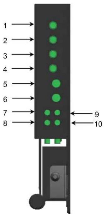
A. BOTTOM PANEL CONTROL

- DC 12V IN
- COMPONENT Y, Pb, Pr & SOUND L, R
- AUDIO OUT
- PC STEREO IN
- D-SUB IN
- DVI IN
- HDMI IN
B. SIDE PANEL CONTROL
- VIDEO 1(AV1) IN
- VIDEO 1(AV1) OUT
- VIDEO 2(AV2) IN
- VIDEO 2(AV2) OUT
- S-VIDEO (Y/C) IN
- S-VIDEO (Y/C) OUT
- AV1, S-VIDEO AUDIO IN
- AV1, S-VIDEO AUDIO OUT
- AV2 AUDIO IN
- AV2 AUDIO OUT
- DC 12V ADAPTOR
INSTRUCTION MANUAL
6
REMOTE FUNCTIONS
Turns the power ON or OFF. There will be a few seconds delay before the display appears.
2. SOURCE
Select pc or video( AV1/AV2/S-Video/DVI/PC) sources.
3. AUTO
Auto geometry adjustment in PC Source.
4. MUTE
Mute the sound.
5. MENU
Activates and exits the On Screen Display.
6. EXIT
Exit the On Screen Display.
7. VOL(
Increases or decreases the level of audio volume.
8. UP/DOWN
Move to OSD menu.
9. ENTER
Accepts your selection or displays the current mode.
10. INFO
Input mode information Display.
11. STILL
Pause the picture.
- PIP (Picture In Picture)
Activates PIP mode.
13. P. INPUT
Select PC or video source.
14. P.POS
Move the position of sub picture for PIP mode.
15. P.SIZE
Change the size of sub and main picture for PIP mode.
16. SWAP
Alternates between main and sub picture.
17. ARC (Aspect Ratio Control)
Select screen ratio.
18. APC (Auto Picture Control)
Select picture mode.
- ACC (Auto Color Control)

Select Colour mode.
- S.SET
Select Sound mode main input or sub input
- PC
Select PC mode(PC,DVI)
- AV
Select AV mode.(AV1,AV2,S-VIDEO)
- COMP
Select COMPONENT mode.
7 INSTRUCTION MANUAL
CONTROLS AND FUNCTIONS
D. FRONT KEY CONTROL
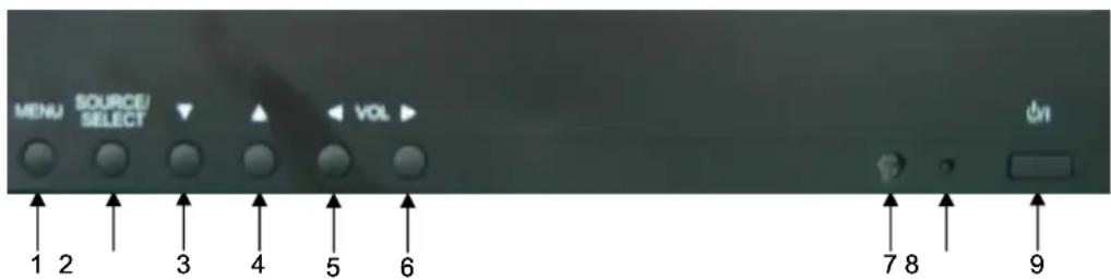
- MENU
Activates and exits the On Screen Display.
- SOURCE / SELECT
Select PC or video source.
Select On Screen Display menu
3 / 4. ▼ / ▲
This button allows user to enter the sub-menu of the activated function
5 / 6. [ VOL ]
Adjust the volume / Adjust menu settings.
- IR Sensor
Remote controller sensor.
- POWER LED
The power LED(next to the power switch) lights with green when the power is turned ON.
The power is turned off by pressing the power switch again and the power LED goes Red.
9. POWER ON/OFF(

Turns the power ON or OFF. There will be a few seconds delay before the display appears.
INSTRUCTION MANUAL
8
CONTROLS AND FUNCTIONS
A: CUSTOM MENU (Only PC mode)
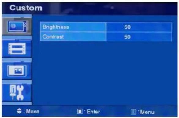
Press the MENU button and then up(▲) / down(▼) button to select the Custom menu.

Press the up(▲) / down(▼) button to select Custom sub menu.
Press (◀) /right(▶) button to adjust picture setting.
Press the MENU button to save.
CONTROLS AND FUNCTIONS
B. Picture / Sound Menu(Only Video mode)
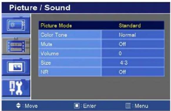
Press the MENU button and then up(▲) / down(▼) button to select the Picture / Sound.
Press the right(▶) or ENTER button.
1. Picture Mode

Press the up(▲) / down(▼) button to select the Picture Mode.
Press the right(▶) or ENTER button and then press up(▲) / down(▼) button to select the desire
Picture Mode.
Press the MENU button to save.
INSTRUCTION MANUAL
CONTROLS AND FUNCTIONS
2. Color Tone

Press the up(▲) / down(▼) button to select the Color Tone.
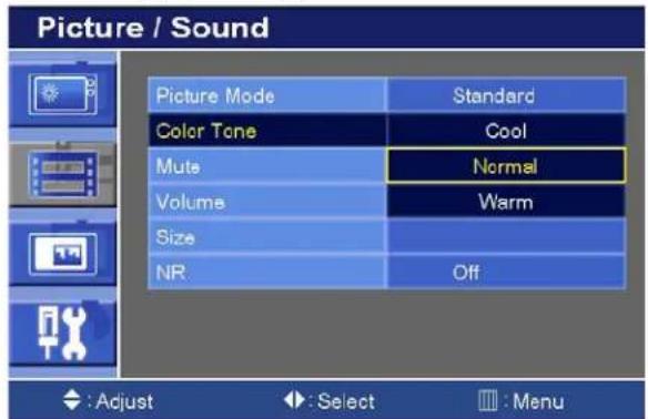
Press the (▶) or ENTER button and then up(▲)/down(▼) button to select the desired color tone.
Press the MENU button to save.
CONTROLS AND FUNCTIONS
3. Mute

Press the up(▲) / down(▼) button to select the Mute.

Press the (▶) or ENTER button and then up(▲)/down(▼) button to select the desired Mute. Press the MENU button to save.
4. Volume

Press the up(▲) / down(▼) button to select the Volume.
Press (◀) /right(▶) button to adjust Volume. Press the MENU button to save.
13
INSTRUCTION MANUAL
CONTROLS AND FUNCTIONS
5. Size

Press the up(▲) / down(▼) button to select the Size.

Press the (▶) or ENTER button and then up(▲)/down(▼) button to select the desired Size. Press the MENU button to save.
6. NR

Press the up(▲) / down(▼) button to select the NR.
INSTRUCTION MANUAL....14
CONTROLS AND FUNCTIONS

Press the (▶) or ENTER button and then up(▲) / down(▼) button to select on or off.
Press the MENU button to save
6. PC (Only PC mode)

Press the up(▲) / down(▼) button to select the PC
Press the ▶ or ENTER button
CONTROLS AND FUNCTIONS

Press the up(▲) / down(▼) button to select PC sub menu
Press the right(▶) or ENTER button and then left (◀) /right(▶) button to adjust PC setting.
Press the MENU button to save.
Auto Adjust: Auto geometry adjustment
Phase: Adjust the number of horizontal picture elements.
H. position: Move image horizontally on screen right or left.
V. position: Move image vertically on screen up or down.
Frequency: Adjust the vertical noise of screen image.
C. PIP MENU

Press the MENU button and then up(▲) / down(▼) button to select the PIP menu.
Press the right(▶) or ENTER button.
INSTRUCTION MANUAL....16
CONTROLS AND FUNCTIONS
1. PIP

Press the up(▲) / down(▼) button to select the PIP.
Press the right(▶) or ENTER button and then press up(▲) / down(▼) button to select the On or Off.
Press the MENU button to save.
2. Input Source

Press the up(▲) / down(▼) button to select the Input Source.
INSTRUCTION MANUAL
CONTROLS AND FUNCTIONS

Press the right(▶) or ENTER button and then press up(▲) / down(▼) button to select the desire Input Source.
Press the MENU button to save.
3. Size

Press the up(▲) / down(▼) button to select the Size.
INSTRUCTION MANUAL
CONTROLS AND FUNCTIONS

Press the right(▶) or ENTER button and then press up(▲) / down(▼) button to select the desire Size.
Press the MENU button to save.
4. Position

Press the up(▲) / down(▼) button to select the Position.
CONTROLS AND FUNCTIONS
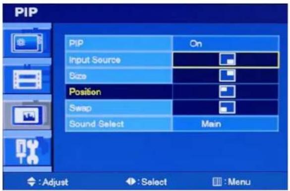
Press the right(▶) or ENTER button and then press up(▲) / down(▼) button to select the desire Position.
Press the MENU button to save.
5. Swap
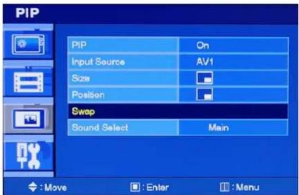
Press the up(▲) / down(▼) button to select the Swap.
Press the right(▶) or ENTER button
INSTRUCTION MANUAL
CONTROLS AND FUNCTIONS
5. Sound Select

Press the up(▲) / down(▼) button to select the Sound Select.
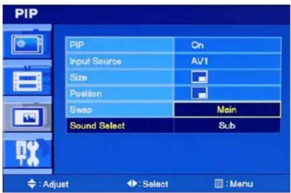
Press the right(▶) or ENTER button and then press up(▲) / down(▼) button to select the desire Sound Select.
Press the MENU button to save.
CONTROLS AND FUNCTIONS
D. SETUP MENU

Press the MENU button and then up(▲) / down(▼) button to select the Setup menu. Press the right(▶) or ENTER button.
1. Reset
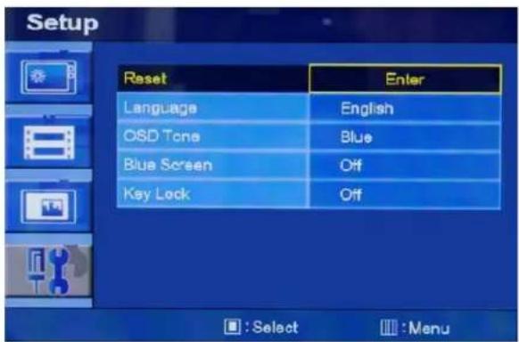
Press ENTER button to select the reset
Reset: Select to reset all setting to the factory default values.
INSTRUCTION MANUAL....22
CONTROLS AND FUNCTIONS
2. Language

Press the up(▲) / down(▼) button to select the Language menu.
Press the right(▶) or ENTER button.

Press the up(▲) / down(▼) button to select language.
Press the MENU button to save.
CONTROLS AND FUNCTIONS
3. OSD Tone

Press the up(▲) / down(▼) button to select the OSD tone menu.
Press the right(▶) or ENTER button

Press the up(▲) / down(▼) button to select the desire OSD Tone.
Press the MENU button to save.
CONTROLS AND FUNCTIONS
4. Blue Screen

Press the up(▲) / down(▼) button to select the blue screen.
Press the right(▶) or ENTER button.
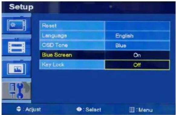
Press the up(▲) / down(▼) button to select on or off.
Press the MENU button to save.
CONTROLS AND FUNCTIONS
5. Key Lock
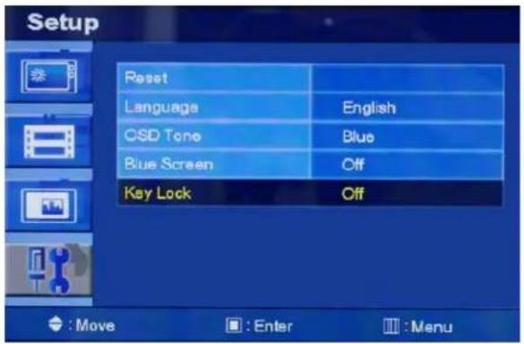
Press the up(▲) / down(▼) button to select the key lock menu.
Press the right(▶) or ENTER button
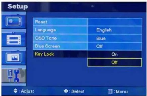
Press the up(▲) / down(▼) button to select on or off
Press the MENU button to save.
MOUNTING GUIDE
Using the VESA standard wall mount design and the 100mm hole pattern on the back panel to install the LCD monitor to the wall.
Wall-mount Installation
- The Monitor fixing bracket to the monitor using the fixing screws provided.
- The monitor fixing bracket assembled with monitor

natural_image
Diagram of a wall-mounted device with a vertical panel and circular components, labeled 'Monitor' (no text or symbols on the diagram itself)
natural_image
Diagram of a wall-mounted device with light bulbs and mounting holes, enclosed in a rectangular frame (no text or symbols)D-SUB CONNECTOR PIN ASSIGNMENTS
▶ PIN ASSIGNMENTS

3. Remote Control Unit And Battery

INSTRUCTION MANUAL....28
POWER MANAGEMENT
This monitor features a power management system to "power down" upon receipt of the VESA DPMS(The display power management signaling) from a VESA DPMS video card. The VESA DPMS-compliant video card performs this signaling system through not sending horizontal, vertical, or sync signal.
This monitor enters an appropriate mode through identifying each of the three modes of the signaling system.
The power management feature of the monitor is comprised of four stages: On(Green), Standby, Suspend, Active off(Red on/off 1 sec) and Unsupported mode(Green).
| MODE LED | COLOR MONITOR | OPERATION |
| ON | GREEN | Normal Operation |
| STANDBY | RED ON/OFF1 SEC | Screen blanks after preset idle timeAnd some electronic circuits or allCircuitry in the monitor shut down. |
| SUSPEND | ||
| ACTIV OFF | ||
| UNSUPPORTES MODE | GREEN | Normal operation but the on screenDisplay will show error massage |
| POWER OFF | RED | Not Operation |
SPECIFICATIONS
| 20" | |
| LCD- Type | 20.1" Diagonal AM-TFT(Active-Matrix) |
| Pixel pitch(mm) : 0.255(H)X 0.255(V) | |
| BRIGHTNESS: 300cd/m2(Typical) | |
| CONTRAST RATIO: 800:1(Typical) | |
| VIEWING ANGLE: 178°/178°(H/V) | |
| RESPONSE TIME: 16msec(Typical) | |
| RESOLUTION (H x V) | 1600X1200 @60Hz |
| FREQUENCY | HORIZONTAL: 31- 80KHzVERTICAL: 56-75Hz |
| INPUT SIGNAL | VIDEO(2ch input 1.0Vp-p, 75Ω terminated, loop-through out) |
| S-VIDEO(1ch input (Y/C) , loop-through out) | |
| COMPONENT(Y,Pb,Pr, Sound L/R) | |
| DVI D(Digital Video Interface) | |
| HDMI(High Definition Multimedia Interface) | |
| PC RGB | |
| AV(composite) Sound in/Out | |
| PC Stereo Sound | |
| Audio Out | |
| ACTIVE DISPLAY AREA (W x H) | 408 mm x 306 mm |
| PACKING DIMENSIONS (W x H x D) | 477mm X 543mm X 205mm |
| WEIGHT | Net Weight : 8.12Kg |
| Gross Weight : 9.72Kg | |
| ELECTRICAL RATINGS | DC 12V/5.83A |
NOTE :
Technical specifications are subject to change without notice.
INSTRUCTION MANUAL....30
TROUBLESHOOTING GUIDE
| TROUBLE | TROUBLESHOOTING TIP |
| No image on display screen | 1. Check that power cord of the Monitor have been connected securely into wall outlet or grounded extension cable or strip.2. Power switch should be in the ON position and LED is lit.3. Check that the Brightness and/or the Contrast adjustments of the Display have not been turned down to minimum levels. |
| "Going to Sleep" message on screen | 1. The signal cable should be completely connected to the video card/computer.2. The video card should be completely seated in its slot and the computer is switched ON. |
| Display image is not centered, too small or too large in PC mode | Push the down key in front side or Auto key in remocon. |
| Vortical or Horizontal noise is present in the picture | Adjust Clock and Phase in the OSD. |
WEEE Symbols
Correct Disposal of This Product (Waste Electrical & Electronic Equipment)
(Applicable in the European Union and other European countries with separate collection systems)
This marking shown on the product or its literature, indicates that it should not be disposed with other household wastes at the end of its working life. To prevent possible harm to the environment or human health from uncontrolled waste disposal, please separate this from other types of wastes and recycle it responsibly to promote the sustainable reuse of material resources. Household users should contact either the retailer where they purchased this product or their local government office, for details of where and how they can take this item for environmentally safe recycling. Business users should contact their supplier and check the terms and conditions of the purchase contract. This product should not be mixed with other commercial wastes for disposal.

INSTRUCTION MANUAL
- CONTENTS
- SAFETY INSTRUCTION
- CAUTION
- ATTENTION
- EMISSION CHARACTERISTICS TESTED BY SEMKO
- CAUTIONS
- FCC RF INTERFERENCE STATEMENT
- NOTE
- ▶ DOC COMPLIANCE NOTICE
- CONNECTING WITH EXTERNAL EQUIPMENT
- BOTTOM PANEL CONTROL
- SIDE PANEL CONTROL
- REMOTE FUNCTIONS
- SOURCE
- AUTO
- MUTE
- MENU
- EXIT
- VOL(
- UP/DOWN
- ENTER
- INFO
- STILL
- P. INPUT
- P.POS
- P.SIZE
- SWAP
- ARC (Aspect Ratio Control)
- APC (Auto Picture Control)
- CONTROLS AND FUNCTIONS
- FRONT KEY CONTROL
- POWER ON/OFF(
- Picture / Sound Menu(Only Video mode)
- Picture Mode
- Color Tone
- Mute
- Volume
- Size
- NR
- PC (Only PC mode)
- PIP MENU
- PIP
- Input Source
- Size
- Position
- Swap
- Sound Select
- SETUP MENU
- Reset
- Language
- OSD Tone
- Blue Screen
- Key Lock
- MOUNTING GUIDE
- Wall-mount Installation
- D-SUB CONNECTOR PIN ASSIGNMENTS
- POWER MANAGEMENT
- TROUBLESHOOTING GUIDE
- WEEE Symbols
- Correct Disposal of This Product (Waste Electrical & Electronic Equipment)
Brand : PANASONIC
Model : PLCD20P
Category : Tracking