
A1WH-6 - Hot plate SMEG - Free user manual and instructions
Find the device manual for free A1WH-6 SMEG in PDF.

| Product Type | Freestanding Gas Stove |
| Brand | Smeg |
| Model | A1WH-6 |
| Energy Source | Natural Gas / LPG (convertible) |
| Number of Burners | 4 |
| Burner Power (Max) | Triple-ring burner: 3.5 kW; Semi-rapid: 1.75 kW; Auxiliary: 1.0 kW |
| Oven Type | Gas oven with thermostat |
| Oven Capacity | 58 liters |
| Grill | Gas grill included |
| Dimensions (W x H x D) | 600 mm x 850 mm x 600 mm |
| Weight | 52 kg |
| Finish | White enamel |
| Control Type | Front knobs |
| Safety Features | Flame failure device on all burners; Oven door safety lock |
| Cleaning | Enamel surfaces: mild detergent and soft cloth |
| Spare Parts Availability | Original Smeg spare parts available through authorized service centers |
| Repairability Index | 8.2 / 10 (based on EU regulations) |
Frequently Asked Questions - A1WH-6 SMEG
User questions about A1WH-6 SMEG
0 question about this device. Answer the ones you know or ask your own.
Ask a new question about this device
Download the instructions for your Hot plate in PDF format for free! Find your manual A1WH-6 - SMEG and take your electronic device back in hand. On this page are published all the documents necessary for the use of your device. A1WH-6 by SMEG.
USER MANUAL A1WH-6 SMEG
INSTRUCTIONS FOR THE INSTALLER: these are for the qualified technician who must carry out a suitable check of the gas system, install the appliance, set it functioning and carry out an inspection test.

INSTRUCTIONS FOR THE USER: these contain user advice, description of the commands and the correct procedures for cleaning and maintenance of the appliance.
1. INSTRUCTIONS FOR SAFE AND PROPER USE
THIS MANUAL IS AN INTEGRAL PART OF THE APPLIANCE AND THEREFORE MUST BE KEPT IN ITS ENTIRETY AND IN AN ACCESSIBLE PLACE FOR THE WHOLE WORKING LIFE OF THE COOKER. WE ADVISE READING THIS MANUAL AND ALL THE INSTRUCTIONS THEREIN BEFORE USING THE COOKER. ALSO KEEP THE SERIES OF NOZZLES SUPPLIED. INSTALLATION MUST BE CARRIED OUT BY QUALIFIED PERSONNEL IN ACCORDANCE WITH THE REGULATIONS IN FORCE. THIS APPLIANCE IS INTENDED FOR DOMESTIC USES AND CONFORMS TO CURRENT REGULATIONS IN FORCE. THE APPLIANCE HAS BEEN BUILT TO CARRY OUT THE FOLLOWING FUNCTIONS: COOKING AND HEATING-UP OF FOOD. ALL OTHER USES ARE CONSIDERED IMPROPER.
THE MANUFACTURER DECLINES ALL RESPONSIBILITY FOR IMPROPER USE.
DO NOT LEAVE THE PACKING IN THE HOME ENVIRONMENT. SEPARATE THE VARIOUS WASTE MATERIALS AND TAKE THEM TO THE NEAREST SPECIAL GARBAGE COLLECTION CENTRE.
IT IS OBLIGATORY FOR THE ELECTRICAL SYSTEM TO BE GROUNDED ACCORDING TO THE METHODS REQUIRED BY SAFETY RULES.

THE PLUG TO BE CONNECTED TO THE POWER CABLE AND THE SOCKET MUST BE THE SAME TYPE AND MUST CONFORM TO CURRENT REGULATIONS.
THE SOCKET MUST BE ACCESSIBLE AFTER THE APPLIANCE HAS BEEN BUILT IN.
IMMEDIATELY AFTER INSTALLATION CARRY OUT A BRIEF INSPECTION TEST OF THE APPLIANCE, FOLLOWING THE INSTRUCTIONS BELOW. SHOULD THE APPLIANCE NOT FUNCTION, DISCONNECT IT FROM THE SUPPLY AND CALL THE NEAREST TECHNICAL ASSISTANCE CENTRE.
NEVER ATTEMPT TO REPAIR THE APPLIANCE.

ALWAYS CHECK THAT THE CONTROL KNOBS ARE IN THE POSITION "ZERO" (OFF) WHEN YOU FINISH USING THE HOB.
NEVER PUT INFLAMMABLE OBJECTS IN THE OVEN: THEY COULD BE ACCIDENTALLY LIGHTED AND CAUSE FIRES.
Introduction
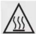
DURING USE THE APPLIANCE BECOMES VERY HOT. TAKE CARE NOT TO TOUCH THE HEATING ELEMENTS INSIDE THE OVEN.
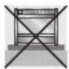
DO NOT INSTALL THIS APPLIANCE ON A RAISED PLATFORM.

THE I.D. PLATE WITH TECHNICAL DATA, REGISTRATION NUMBER AND BRAND NAME IS POSITIONED VISIBLY IN THE STORAGE COMPARTMENT. THE PLATE MUST NOT BE REMOVED.

DO NOT PUT PANS WITHOUT PERFECTLY SMOOTH AND FLAT BOTTOMS ON THE COOKING HOB GRIDS. NEVER USE THE COOKING HOB AS A WORK SURFACE.
DO NOT USE CONTAINERS OR BROILERS THAT EXTEND BEYOND THE OUTER PERIMETER OF THE HOB.

THE USE OF THIS APPLIANCE IS NOT PERMITTED TO PEOPLE (INCLUDING CHILDREN) OF REDUCED PHYSICAL AND MENTAL ABILITY, OR LACKING IN EXPERIENCE IN THE USE OF ELECTRICAL APPLIANCES, UNLESS THEY ARE SUPERVISED OR INSTRUCTED BY ADULTS OR PEOPLE RESPONSIBLE FOR THEIR SAFETY.

THIS APPLIANCE IS MARKED ACCORDING TO THE EUROPEAN DIRECTIVE 2002/96/EC ON WASTE ELECTRICAL AND ELECTRONIC EQUIPMENT (WEEE). THIS GUIDELINE IS THE FRAME OF A EUROPEAN-WIDE VALIDITY OF RETURN AND RECYCLING ON WASTE ELECTRICAL AND ELECTRONIC EQUIPMENT.

BEFORE THE APPLIANCE IS PUT INTO OPERATION, ALL THE LABELS AND PROTECTIVE FILMS APPLIED INSIDE OR OUTSIDE MUST BE REMOVED.

The manufacturer declines all responsibility for damage to persons or things caused by non-observance of the above prescriptions or by interference with any part of the appliance or by the use of non-original spares.
2. INSTALLATION OF THE APPLIANCE

It is the law that all gas appliances are installed by competent persons. Corgi gas installers are approved to work to safe and satisfactory standards. All gas installation, servicing and repair work must be in accordance with the gas safety regulations 1984 (installation and use) as amended 1990.
It may be installed against walls one of which is higher than the worktop surface, at least 50 mm from the side of the appliance, as shown in the installation class drawings A and B. Wall units or extractor hoods installed above the appliance's work-top must be at least 750 mm above it.

SLOT IN

FREE STANDING
2.1 Electrical connection
Make sure that the power line voltage matches the specifications indicated on the rating plate located inside the storage compartment.
This rating plate must never be removed.

The plug at the end of the power cable and the wall socket must be the same type (conforming to regulations in force). Check that the power line is adequately grounded. Do not use reducers, adapters or shunts.

On the power line, install an omnipolar cut-off device with contact cut-off distance greater than or equal to 3 mm, located in an easily accessible position near the unit.
If the power cable is replaced, the wire section on the new cable must not be less than 1.5 mm ^2 (3 x 1.5 cable), keeping in mind that the end to be connected to the hob must have the ground wire (yellow-green) longer by at least 20 mm. Use only the special cables available at our Service Centres.


The manufacturer declines all responsibility for damage to persons or things caused by non-observance of the above prescriptions or by interference with any part of the appliance.

2.2
2.3 Ventilation requirements
The room containing the appliance should have an air supply in accordance with B.S. 5440 part 2 1989.
- All rooms require an opening window or equivalent, and some rooms will require a permanent vent as well.
- For room volumes up to 5 m ^3 an air vent of 100 cm ^2 is required.
- If the room has a door that opens directly to the outside, and the room exceeds 1 m^3 no air vent is required.
- For room volumes between 5 m^-3 and 10 m^3 an air vent of 50 cm^2 is required.
- If there are other fuel burning appliances in the same room B.S. 5440 part 2 1989 should be consulted to determine the air vent requirements.
- This appliance must not be installed in a bed sitting room of less than 20 m^3 or in a bathroom or shower room.
Windows and permanent vents should therefore not be blocked or removed without first consulting a Corgi gas installer.
Failure to install appliances correctly is dangerous and could lead to prosecution.
2.4
2.5 Connecting to natural and LPG gas (Please see connection diagram)
This type of connection is possible on both built-in and free-standing appliances. Make the connection to the appliance using flexible bayonet style hose in accordance to B.S. 669. The hose connection at the rear of the appliance has a 12 BSP internal thread. Please use seal C between the flexible connection L and the appliance supply tube B.
After completing the installation, check for any leaks with a soapy solution, never with a naked flame. Make sure that the hose complies with the regulations in force.
When connecting to an LPG cylinder use a pipe with adapter for connection to the pressure regulator.
If connecting to LPG the bayonet hose must have red bands on it.
Take care that the hose is not crushed or damaged.

3. ADAPTATION TO DIFFERENT TYPES OF GAS
Before performing any cleaning or maintenance work, detach the appliance from the electrical socket.
The cooker hob is set for natural gas G20 (2H) at a pressure of 20 mbar. In the case of functioning with other types of gas the burner nozzles must be changed and the minimum flame adjusted on the gas taps. To change the nozzles, proceed as described below.
3.1 Replacement of nozzles on the hob
This operation requires no primary air regulation.
- Extract the grids and remove all the caps and flame-spreader crowns;
-
Unscrew the burner nozzles with a 7 mm socket wrench;
-
Replace the nozzles according to the type of gas to be used and the description in paragraph "3.2 Burner and nozzle characteristics table".
Replace the burners in the correct position.

natural_image
Technical diagram showing a mechanical assembly with a piston and nut, including a magnified inset of the component (no text or labels)3.2 Burner and nozzle characteristics table
| Burner | Rated heating capacity (kW) | LPG – G30/G31 28/37 mbar | ||||
| Nozzle diameter1/100 mm | By-pass mm1/100 | Reduced flowrate (W) | Flowrate g/h G30 | Flowrate g/h G31 | ||
| Auxiliary 1.05 50 30 400 76 75 | ||||||
| Semi-rapid 1.8 65 33 500 131 129 | ||||||
| Rapid 3 85 45 800 218 215 | ||||||
| Triple crown 4.0 100 65 1600 290 286 | ||||||
| Fish pan 1.9 68 45 800 138 136 | ||||||
| Burner | Rated heating capacity (kW) | NATURAL GAS – G20 20 mbar | ||||
| Nozzle diameter1/100 mm | Reduced Flowrate (W) | |||||
| Auxiliary | 1.05 | 72 | 400 | |||
| Semi-rapid | 1.8 | 97 | 500 | |||
| Rapid | 3 | 115 | 800 | |||
| Triple crown | 4.0 | 135 | 1600 | |||
| Fish pan | 1.9 | 94 | 800 | |||
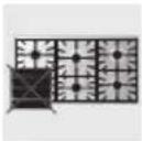
3.3 Arrangement of burners on cooking hob
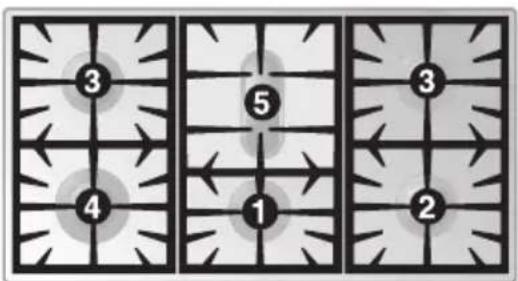
BURNERS
1 Auxiliary
2 Semi rapid
3 Rapid
4 Ultra rapid
5 Fish pan
4. FINAL OPERATIONS
After replacing the nozzles, reposition the flame-spreader crowns, the burner caps and the grids.
After adjustment to a different kind of gas from the one for which the cooker has been tested, replace the plate inside the storage compartment with one corresponding to the new kind of gas. This plate can be obtained from your nearest Authorised Assistance Centre.
4.1 Adjustment of minimum for natural gas
Light the burner and take it to the minimum. Remove the gas tap knob and turn the adjustment screw inside or at the side of the tap shaft (depending on the model) until there is a regular minimum flame. Replace the knob and check burner flame stability: (rapidly turning the knob from maximum to minimum position, the flame should not go out). Repeat the operation on all the gas taps.

natural_image
Two mechanical tools with textured surfaces, one showing a curved handle and the other a circular component (no text or symbols)4.2 Regulation of minimum for LPG
For regulating the minimum with LPG, the screw at the side of the tap rod must be turned clockwise all the way.
The bypass diameters for each individual burner are shown in paragraph "3.2 Burner and nozzle characteristics table". Once the regulation has been completed, replace the seal on the by-passes using paint or similar materials.
4.3 Positioning and levelling of the appliance
Having carried out the electricity and gas hook-up, level the appliance using the four adjustable legs.
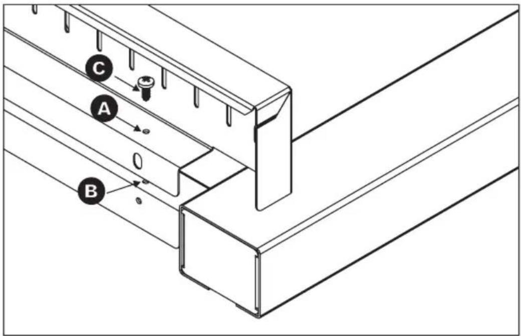
4.4 Mounting the rear top upstand
- Position the upstand above the top, taking care to align holes A with holes B.
- Secure the upstand to the top by tightening screws C.
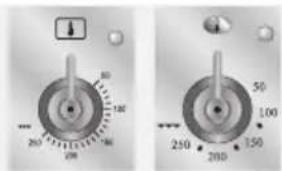
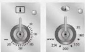
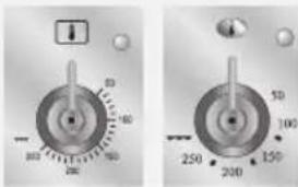
5. DESCRIPTION OF CONTROLS
5.1 Front control panel
All the cooker controls and commands are on the front panel.
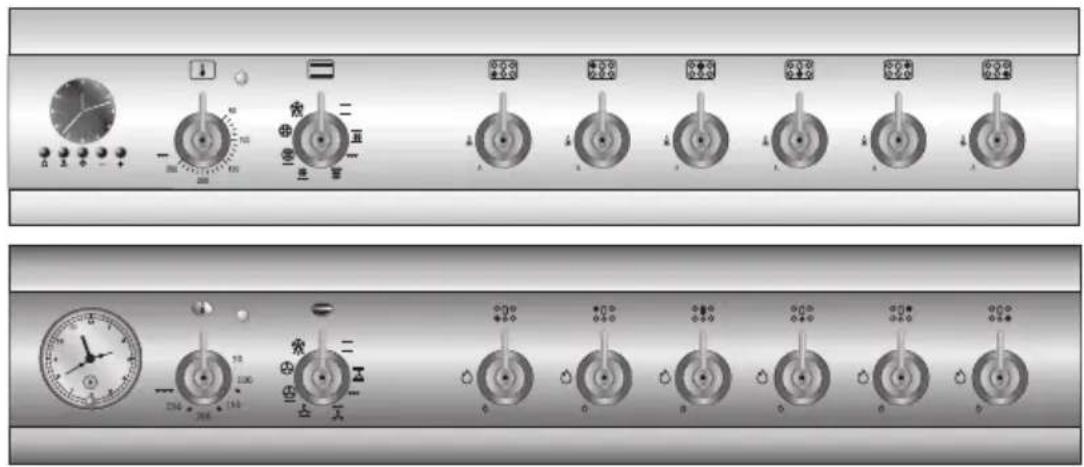
DESCRIPTION OF SYMBOLS
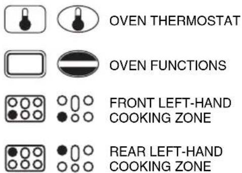

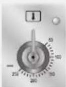
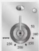
THERMOSTAT KNOB
Selection of cooking temperature is carried out by turning the knob clockwise to the required temperature, between 50° and 250°C.
The tell-tale light comes on to indicate that the oven is warming up.


When it goes out it means that the required temperature has been reached. Regular flashing means that oven temperature is being constantly maintained at the programmed level.
FUNCTION SWITCH KNOB
Turn the knob to select from the following functions:
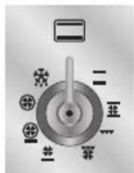


NO FUNCTION SET

UPPER AND LOWER HEATING ELEMENT


UPPER AND LOWER HEATING ELEMENT + VENTILATION GRILL ELEMENT


LOWER HEATING
ELEMENT +
VENTILATION
LOWER HEATING
ELEMENT +
VENTILATED
HEATING ELEM.
VENTILATED
HEATING ELEMENT +
VENTILATION
DEFROSTING
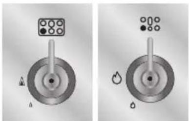
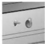
COOKING HOB BURNER COMMAND KNOB
To light the flame, press and turn the knob anticlockwise to the large flame symbol. Adjust the flame by turning the knob to the area comprised between maximum and minimum marks. To turn off, set the knob to either "zero".
natural_image
Mechanical component diagram showing a rotating wheel with labeled parts (A and B) and a top panel (no text or symbols beyond labels)
natural_image
Pure mechanical component diagram without any text, numbers, or symbols5.2 Analog Programmer

To set the correct time, pull out the knob A and turn it clockwise.
Before setting programmer, select desired cooking mode and temperature.
5.2.2 Timed cooking
Select the function and temperature required before setting the cooking duration. Now pull the knob A out and turn it clockwise to locate the minute minder hand C aligned with the hour hand. Now turn the knob A clockwise to set the cooking duration in the window B.
5.2.3 Delayed start cooking
Turn the knob A clockwise until a 0 appears in the window B. Now pull the knob A out and turn it clockwise to locate the minute minder hand C on the chosen cooking start time (the cooking star time cannot be more than 12 hours ahead of the current time). Now turn the knob A either to the 🔊 symbol for cooking in manual mode, or to the required cooking duration (all oven elements will be disconnected at the end of the time set).
5.2.4 Manual mode cooking
Turn the knob A clockwise until a 0 appears in the window B. Now pull the knob A out and turn it clockwise to locate the minute minder hand C aligned with the hour hand.
Now turn the knob A clockwise again until the ⏻ symbol appears in the window B.
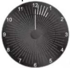
5.3 Electronic Analogue Clock (on some models only)

natural_image
Circular dial with numbered segments and six small icons below (bell, lock, smiley face, clock, minus, plus) — no readable text or symbols on the dial itself.LIST OF FUNCTIONS

MINUTE-MINDER BUTTON

AUTOMATIC SWITCH-OFF TIMING BUTTON

TIME SETTING AND RESET

VALUE DECREASE BUTTON

VALUE INCREASE BUTTON
5.3.1 Setting the time
When the oven is used for the first time, or after a power blackout, the display flashes on and off at regular intervals. Press the ⏻ key for 1/2 seconds to stop the display flashing and start setting of the current time.
Press the value modification keys — or + to increase or decrease by one minute for each time a key is pressed.
Press one of the two value modification keys until the current time appears. The clock will start from the time set 6/7 seconds after the last key is pressed.
At the end of each programmed cooking operation, the clock gives 8 beeps, repeated 3/4 times at intervals of about 1 and a half minutes. The beeps can be stopped at any moment by pressing any key.
5.3.2 Minute-minder
This function does not stop cooking but just triggers the beeps.
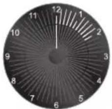
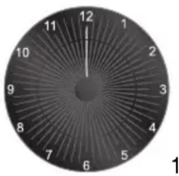
- When the ⏻ key is pressed the display illuminates, appearing as shown in figure 1;
- Press the + or - keys within 6/7 seconds to set the minute-minder. Whenever a key is pressed, 1 outside segment, representing 1 cooking minute will light up (figure 2 shows 10 cooking minutes).
- The countdown will start 6/7 seconds after the last key is pressed; at the end of it, you will hear the beeps.
- During cooking with countdown, the current time can be displayed by pressing the 🔗 key once; press again to return to the minute-minder display.
- At the end of the countdown, the oven has to be switched off by hand, by turning the thermostat and the function selector to 0.
natural_image
Circular analog clock face with hour markers (no text or symbols beyond numbers)1
natural_image
Circular analog clock face with hour and minute hands (no numbers or text)2
5.3.3 Programming
Cooking duration time: the 2^nd button can be used to set the cooking time. Before setting it, turn the thermostat to the cooking temperature of choice and the function selector knob to any setting. To set the cooking time, proceed as follows:
- Press the 📊 key for 1/2 seconds; the pointer will move to position 12 (Fig. 1).
- Use the - and + keys to set the cooking time; whenever the + key is pressed, 1 minute will be added to the cooking time, and every 12 minutes a new inside segment will light up (figure 2 shows a cooking time of 1 hour).
- Once the required time has been set, cooking will start about 6 seconds after the last time the - or + key is pressed.
- Once cooking has started, the display will show the current time, represented by the constantly on segments, and the minutes left until cooking finishes, represented by the flashing segments (every flashing segments indicates 12 minutes of cooking time left).
- When the end of the cooking time is reached, the timer will switch off the oven heating elements, the beeps will start and the numbers on the dial will flash.
- The cooking time can also be reset by deleting the program set; pressing the central key ⏻ for 1 or 2 seconds will delete the time set and the oven will have to be switched off by hand.
natural_image
Circular analog clock face with hour and minute hands (no numbers or text)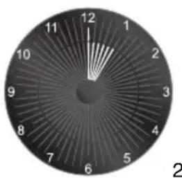
natural_image
Circular analog clock face with hour and minute hands (no numbers or text)Caution: cooking times of more than 6 hours cannot be set.
Cooking start: as well as setting a cooking duration time, the user can also set the cooking start time (up to 12 hours after the current time). To set the cooking start/end time, proceed as follows.
- Set the cooking duration time as described in the previous point.
- Within 6/7 seconds after the last time the - or + keys are pressed, press the ⚪ key to set the cooking start time. The display will show the current time with the inside segments indicating the cooking end time illuminated. Use the - and + keys to set the cooking start time.
- 6/7 seconds after the last time a key is pressed, the display will show the current time and the cooking start and end times, indicated by the illuminated inside segments. The segments on the display will be constantly on until the current time is the same as the cooking start time; as soon as the current time reaches the cooking start time set, all the inside segments will start to flash, indicating that the oven has started cooking.
- When the end of the cooking time is reached, the timer will switch off the oven heating elements, the beeps will start and the numbers on the dial will flash.
- To reset the entire program set, keep the central key ☑ pressed for 1 or 2 seconds: if cooking has already started the oven will have to be switched off by hand.
- The image on the right shows an example of programming: the current time is 7.06 and cooking is programmed to start at 8 o'clock and finish at 9.
- At 8 o'clock, the inside segments between 8 and 9 will start to flash and the hour pointer will remain still.
natural_image
Circular analog clock face with hour markers (no text or symbols beyond numbers)Caution: for the oven to start cooking after the programming procedure just described, the thermostat and function selector must be properly set on the temperature and function required.
5.3.4 "DEMO" Function
Models with analogue/digital programmer feature a "DEMO" function which deactivates the heating elements while leaving the other functions unchanged. To activate it, simply press the ⏻, and keys for 3/4 seconds. A confirmation beep will inform the user that the function is active. To deactivate it, simply repeat the same procedure.
6. USE OF THE COOKING HOB
6.1 Lighting of the cooking hob burners
Before lighting the hob burners check that the flame caps are in the correct position and that their burner caps are in place, making sure that the holes A in the flame caps correspond to the spark plugs and thermocouples.
Grid B should be used with Chinese woks.

Each knob corresponds to the burner indicated. The appliance is equipped with an electric lighting device. To light the burners, press and turn the knob anticlockwise to the large flame symbol ▲ / 🔒
natural_image
Two identical diagrams showing a mechanical component with circular features and symbols, no text or labels present.Keep the knob pressed for about 2 seconds to let the thermocouple heat up.
If the burner turns off when the knob is released, it means that the thermocouple isn't hot enough. Repeat ignition and keep the knob pressed longer.
Once the burner has been ignited, the flame can be regulated as required.
Always check that the control knobs are in the position ○ (off) when you finish using the hob.

If the burners turn off accidentally, a safety device will trip after about 20 seconds to cut off gas flow (even with the gas tap open).
6.2 Practical advice for using the cooking hob burners
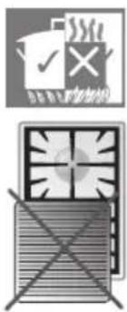
For better use of the burners and lower gas consumption, use covered containers that are proportional in size to the burner to prevent the flame from licking the sides (see paragraph "6.3 Diameter of containers"). When water reaches the boiling point, lower the flame so that it doesn't overflow. To avoid burns or damage to the hob, all recipients or griddle plates must be placed within the perimeter of the cooking hob. All containers have to have a flat and smooth bottom. When using fats or oils, be extremely careful that they don't overheat and catch fire.
If the flame accidentally goes out, turn off the control knob and wait at least 1 minute before trying to re-light the burner.
6.3 Diameter of containers
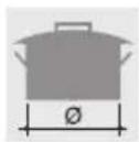

BURNERS
∅ min. and max. (in cm)
1 Auxiliary
2 Semi rapid
3 Rapid
4 Ultra rapid
5 Fish pan
12-14
16-20
18-26
20-26
use special oval-shaped pan
7. USE OF THE OVEN

Before using the oven make sure that the analog programmer shows the 🔊 symbol (see paragraph "5.2.4 Manual mode cooking").
In models equipped with analogue digital timer, the user has only to press the central key for 1/2 seconds to enable use of the oven on first use or after a power blackout.
7.1 Warnings and general advice
Before using the oven for the first time, pre-heat it to maximum temperature (250°C) long enough to burn any manufacturing oily residues which could give the food a bad taste.

To prevent any steam in the oven creating problems, open the door in two stages: half open (5 cm approx.) for 4-5 seconds and then fully open. To access food, always leave the door open as short a time as possible to prevent the temperature in the oven from falling and ruining the food.

natural_image
Illustration of a mechanical component with a 50mm dimension label (no readable text or symbols)
During cooking, do not cover the bottom of the oven with aluminium or tin foil, and do not place pans or trays on it; this may damage the enamel coating. If you wish to use greaseproof paper, position it so that it does not interfere with the hot air circulation inside the oven.
7.2 Oven Light
It comes on when the function switch knob is turned to any position.
The appliance is equipped with a cooling system, which comes into operation as soon as a cooking function is selected. This is also the case for cooking with the minute minder.
Fans cause a steady outflow of air from the rear top skirt board on the rear of the cooking hob, which may continue for a brief period of time even after the oven has been turned off.
This ventilation system ensures that the temperatures on the outside of the appliance meet the standards required by the current regulations.
7.4 Storage drawer
The storage drawer is at the bottom of the cooker, underneath the oven. For access, pull the bottom of the door.
Never store inflammable materials such as rags, paper or the like. The compartment is intended only for holding the metal accessories of the range.

natural_image
3D diagram of a mechanical component with a downward arrow indicating force or direction (no text or symbols)
Never open the storage compartment when the oven is on and still hot. The temperature inside may be very high.
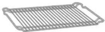
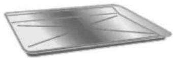
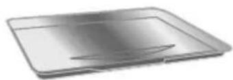
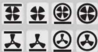
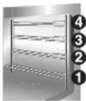
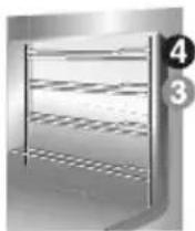
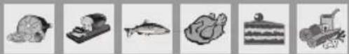
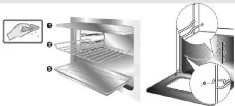
8. AVAILABLE ACCESSORIES
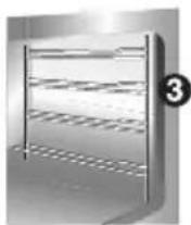
The oven features 4 support positions for plates and racks of different height.
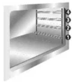
natural_image
Interior view of a stainless steel kitchen appliance with numbered compartments (1-4) shown in the corner, no text or symbols on the main body.Oven grill: for cooking food on plates, small cakes, roasts or food requiring light grilling.

Plate grill: for placing above plate for cooking foods that might drip.
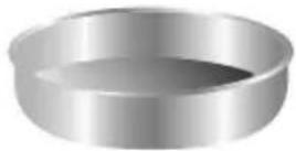
Oven plate: useful for catching fat from foods on the grill above.
Pastry plate: for baking cakes, pizza and oven desserts.
natural_image
Metallic rectangular tray with a flat lid and a small protrusion on the side (no text or symbols visible)Roasting spit: useful for cooking chicken, sausages and anything else requiring uniform cooking over the whole surface.

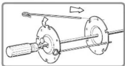
natural_image
Technical line drawing of two mechanical components: a fork and a flanged shaft (no text or symbols)Spit supports: to be inserted in the holes of the oven plate before mounting the roasting spit.

natural_image
Two abstract line drawings with jagged ends, no text or symbols present
Accessories on Request
You can order the lower base through Authorised Assistance Centres.
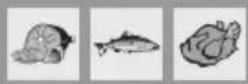
9. COOKING HINTS
9.1 Traditional cooking
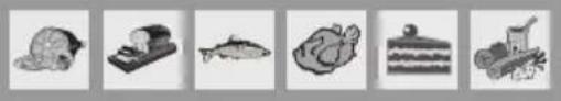
natural_image
Six grayscale icons representing various objects: turtle, boat, fish, bread, cake, and tractor (no text or symbols)FUNCTION SWITCH

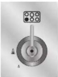
THERMOSTAT SELECTOR SWITCH FROM 50° TO 250°C


This traditional cooking method, in which heat comes from above and below, is suitable for cooking food on a single level. You have to preheat the oven until the set temperature is reached. Place the food in the oven only after the thermostat indicator light has turned off. very fatty meats may be put in when the oven is still cold. Put frozen meat in immediately, without waiting for it to thaw. The only precaution you need to take is to set the temperature about 20^ C lower and cooking time about 1/4 longer than you would for fresh meat.

Use high-rim pans to prevent fat splashing and dirtying the sides of the oven.
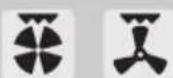
9.2 Hot-air cooking

natural_image
Six grayscale illustrations of various objects and objects, including a turtle, computer, fish, bread, cake, and newspaper (no text or symbols)FUNCTION SWITCH
natural_image
Grid of nine black-and-white icons representing various aircraft or signal symbols (no text or labels)THERMOSTAT SELECTOR SWITCH FROM 50° TO 250°C
This system is suitable for cooking on several levels, including different types of food (fish, meat etc.), without the tastes and smells mingling. Air circulation in the oven ensures a uniform distribution of heat. Pre-heating is not necessary.

Multiple cooking is possible as long as the cooking temperature of the different foods is the same.

Keep the oven door closed during grilling. Grilling with the door open could permanently damage the oven and affect safety of operation.
9.3 Grill cooking
FUNCTION SWITCH
THERMOSTAT SWITCH AT MAXIMUM


Permits rapid browning of foods. You are advised to place the pan in the highest guide. For short-term cooking of small quantities, place the grid in the third guide from the bottom. For long-term cooking and grills, put the grid in the lowest guide in accordance with the size of the pieces.
Make sure that the oven door is closed during cooking.

Keep the oven door closed during grilling. Grilling with the door open could permanently damage the oven and affect safety of operation.
9.4 Hot-air grilling
FUNCTION SWITCH
THERMOSTAT SWITCH FROM 50° TO 250°C

Ensures uniform heat distribution with greater heat penetration into the food. Food will be lightly browned on the outside and remain soft inside. Keep the oven door closed during cooking.
9.5 Defrosting
natural_image
Six grayscale illustrations of various food and beverage items: bread, fish, meat, bread, milk, and soda (no text or symbols)FUNCTION SWITCH

THERMOSTAT SWITCH IN POSITION 0

The flow of air produced by the fan ensures quicker defrosting. The air circulating inside the oven is at room temperature.

The advantage of defrosting at room temperature is that it does not alter the taste and appearance of the food.
9.6 Spit cooking
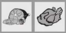
FUNCTION SWITCH
THERMOSTAT SWITCH FROM 50° TO 200°C
Prepare the spit with the food, blocking fork screws A. Insert frame B into the third guide from the bottom. Remove handle D and position the spit shaft so that pulley E is guided on the link of frame B in the right side. Insert the drip tray into the oven as far as it will go until the tip of the rod is in line with the hole C. Now rock the frames B to insert the tip of the rod into the drive connection C of the rotisserie motor on the side of the oven. Pour a bit of water into the pan to avoid smoke from the dripping.
Keep the oven door closed during cooking.
Cooking procedures with grill and rotisserie must never last more than 60 minutes.

It is normal for the thermostat light to go on and off intermittently during cooking. This indicates the temperature inside the oven is regular.

natural_image
Pure electrical circuit lines without any symbols
natural_image
Mechanical assembly diagram showing a shaft, flange, and rotating shaft with motion arrow (no text or labels)
CAUTION: the frames B must be fitted as shown in the diagram
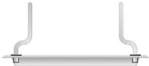
natural_image
Pure diagram of a horizontal pipe or support structure with two vertical flanges and two base supports (no text or symbols)9.7 Recommended cooking table
Cooking times, especially meat, vary according to the thickness and quality of the food and to consumer taste.
TRADITIONAL COOKING

| LEVELFROM BELOW | TEMPERATURE(°C) | TIME INMINUTES (*) | |
| FIRST COURSES | |||
| LASAGNE | 2 - 3 | 210 - 230 | 30 |
| OVEN-BAKED PASTA | 2 - 3 | 210 - 230 | 40 |
| MEAT | |||
| ROAST VEAL | 2 | 170 - 200 | 30 - 40 / KG. |
| ROAST BEEF | 2 | 210 - 240 | 30 - 40 / KG. |
| ROAST PORK | 2 | 170 - 200 | 30 - 40 / KG. |
| CHICKEN | 2 | 170 - 200 | 45 - 60 |
| DUCK | 2 | 170 - 200 | 45 - 60 |
| GOOSE - TURKEY | 2 | 140 - 170 | 45 - 60 |
| RABBIT | 2 | 170 - 200 | 50 - 60 |
| LEG OF LAMB | 1 | 170 - 200 | 15 / KG. |
| ROAST FISH 1 - 2 170 - 200 ACCORDING TO DIMENSIONS | |||
| PIZZA 1 - 2 210 - 240 40 - 45 | |||
| DESSERTS | |||
| MERINGUE | 1 - 2 | 50 - 70 | 60 - 90 |
| SHORT PASTRY | 1 - 2 | 170 - 200 | 15 - 20 |
| CIAMBELLA | 1 - 2 | 165 | 35 - 45 |
| SAVOYARDS | 1 - 2 | 150 | 30 - 50 |
| BRIOCHES | 1 - 2 | 170 - 200 | 40 - 45 |
| FRUIT CAKE | 1 - 2 | 170 - 200 | 20 - 30 |
(*) = WITH PREHEATED OVEN
GRILLING


| LEVELFROM BELOW | TIME IN MINUTES | ||
| FIRST SURFACE SECOND SURFACE | |||
| PORK CHOPS | 4 | 7 - 9 | 5 - 7 |
| FILLET OF PORK | 3 | 9 - 11 | 5 - 9 |
| FILLET OF BEEF | 3 | 9 - 11 | 9 - 11 |
| LIVER | 4 | 2 - 3 | 2 - 3 |
| VEAL ESCALOPES | 4 | 7 - 9 | 5 - 7 |
| HALF CHICKEN | 3 | 9 - 14 | 9 - 11 |
| SAUSAGES | 4 | 7 - 9 | 5 - 6 |
| MEAT-BALLS | 4 | 7 - 9 | 5 - 6 |
| FISH FILLETS | 4 | 5 - 6 | 3 - 4 |
| TOAST | 4 | 2 - 4 | 2 - 3 |
HOT-AIR COOKING

natural_image
Grid of nine black-and-white icons representing various aircraft or signal symbols (no text or labels)| LEVELFROM BELOW | TEMPERATURE(°C) | TIMEIN MINUTES | |
| FIRST COURSES | |||
| LASAGNE | 2 | 190 - 210 | 20 - 25 |
| OVEN-BAKED PASTA | 2 | 190 - 210 | 25 - 30 |
| CREOLE RICE | 2 | 190 - 220 | 20 - 25 |
| MEAT | |||
| ROAST VEAL | 2 | 150 - 170 | 65 - 90 |
| ROAST PORK | 2 | 150 - 160 | 70 - 100 |
| ROASTED BEEF | 2 | 160 - 170 | 65 - 90 |
| FILLET OF BEEF | 2 | 160 - 180 | 35 - 45 |
| ROAST LAMB | 2 | 130 - 150 | 100 - 130 |
| ROAST BEEF | 2 | 170 - 180 | 40 - 45 |
| ROAST CHICKEN | 2 | 170 | 70 - 90 |
| ROAST DUCK | 2 | 160 - 170 | 100 - 160 |
| ROAST TURKEY | 2 | 150 - 160 | 160 - 240 |
| ROAST RABBIT | 2 | 150 - 160 | 80 - 100 |
| ROAST HARE | 2 | 160 - 170 | 30 - 50 |
| ROAST PIGEON | 2 | 140 - 170 | 15 - 25 |
FISH 2 - 3 150 - 170 ACCORDING
TO DIMENSIONS
| PIZZA 2 - 3 210 - 240 30 - 50 | |||
| DESSERTS (PASTRIES) | |||
| CIAMBELLA | 2 - 3 | 150 - 170 | 35 - 45 |
| FRUIT CAKE | 2 - 3 | 170 - 190 | 40 - 50 |
| SPONGE-CAKE | 2 - 3 | 190 - 220 | 25 - 35 |
| BRIOCHES | 2 - 3 | 160 - 170 | 40 - 60 |
| STRUDEL | 1 - 2 | 150 | 25 - 35 |
| SAVOYARD PUDDING | 2 - 3 | 160 - 170 | 30 - 40 |
| BREAD | 2 - 3 | 190 - 210 | 40 |
| TOAST | 1 - 2 | 220 - 240 | 7 |
10. CLEANING AND MAINTENANCE
10.1 Cleaning stainless steel
Before performing any operations requiring access to powered parts, switch off the power supply to the machine.

To keep stainless steel in good condition it should be cleaned regularly after use. Let it cool first.
10.1.1 Ordinary Daily Cleaning
To clean and preserve the stainless steel surfaces, always use only specific products that do not contain abrasives or chlorine-based acids.
How to use: pour the product on a damp cloth and wipe the surface, rinse thoroughly and dry with a soft cloth or deerskin.
10.1.2 Food stains or residues
Do not use metallic sponges or sharp scrapers: they will damage the surface.
Use normal non-abrasive products for steel, and a wooden or plastic tool if necessary.
Rinse thoroughly and dry with a soft cloth or deerskin.
Do not allow residues of sugary foods (such as jam) to set inside the oven. If left to set for too long, they might damage the enamel lining of the oven.

10.2 Cleaning of cooking hob components
10.2.1 Grids
Extract the grids (the central one first, then the side ones). Clean with warm water and non-abrasive detergent, taking care to remove incrustation. Reassemble positioning the side ones first and then the central one.
10.2.2 Burner caps, flame cap crowns and burners
To facilitate cleaning, caps, flame cap crowns, and burners are all removable. To remove the flame separating crown of the fish hob, loosen the two screws exposed after having removed the cap. Wash all parts with warm water and non-abrasive detergent taking care to remove all tough spots. Wait for all parts to be fully dry before remounting.
Replace the flame-spreader crowns, checking that they are positioned in their housing with their respective caps, taking care that flame-spreader holes A correspond to the spark plugs and the thermocouples.

10.2.3 Ignition plugs and thermocouples
To work well, the ignition plugs and thermocouples must always be very clean. Check them frequently and clean them with a wet rag if necessary. Any dry residue should be removed with a toothpick or a needle.

10.3 Cleaning of the oven

For best oven upkeep clean regularly after having allowed to cool. Take out all removable parts.
Remove the side runners by lifting them at the front and extracting them from the hole at the back.
• DO NOT USE A STEAM JET FOR CLEANING THE INSIDE OF THE OVEN.
- Clean the oven grill and side guides with hot water and non-abrasive detergent. Rinse and dry.
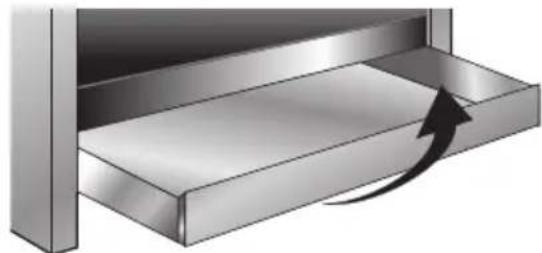
For easier cleaning, the storage drawer underneath the oven can be completely removed.
Pull it right out and raise the front (as for an ordinary drawer).
natural_image
Diagram of a metallic mechanical component with an arrow indicating force or motion (no text or symbols present)10.3.1 Self-cleaning liners
The main oven is equipped with continuous self-cleaning enamelled liners.
These liners make the oven easier to clean and ensure its efficiency over time.
10.4.1 Using the self-cleaning liners
Periodically, to prevent food residues and unpleasant smells from accumulating inside the oven, the appliance should be operated empty at temperatures of not less than 200^ C for a time varying from 30 to 60 minutes, in order to allow the self-cleaning liners to oxidise the residues present; when the oven has cooled, these will then be removed with a damp sponge
10.4.2 Looking after the self-cleaning liners
The liners should not be cleaned with abrasive creams or ordinary detergents. Use a damp sponge only, so as not to damage the special characteristics of the enamel which coats the liners.
10.4.3 Assembling the self-cleaning liners
- Remove all accessories from the oven;
- Remove the side grilles (fig.1);
- Extract the side liners "F" and "G"(fig. 2);
- Remove the back panel "A" after undoing the threaded ring-nuts "C" (fig. 2).
- Reassemble the panels, restoring them to their original position.

10.5 Door glass
The door glass should always be kept clean. Use absorbent kitchen paper to clean. In case of tough spots, clean with a damp sponge using regular detergent.
11. EXTRAORDINARY MAINTENANCE
The oven may require extraordinary maintenance or replacement of parts subject to wear such as seals, bulbs, and so on. The following instructions describe how to carry out these minor maintenance operations.

Before any intervention, disconnect the power supply of the device.
11.1 Replacement of light bulb
Remove cover A by twisting anticlockwise, replace bulb B with another similar bulb. Refit the cover A.


Only use oven bulbs (T 300°C).
11.2 Removing the door
Open the door completely and fit the pins (supplied) into the holes from the inside. Close the door to an angle of about 45^ , lift it and remove it from its seat. To replace, fit the hinges into the grooves provided, then lower the door until it comes to rest and extract the pins. If the pins are lost, two screwdrivers can also be used.

natural_image
Diagram showing three views of a kitchen appliance with a 45-degree angle indicator (no text or symbols present)11.3 Oven door seal
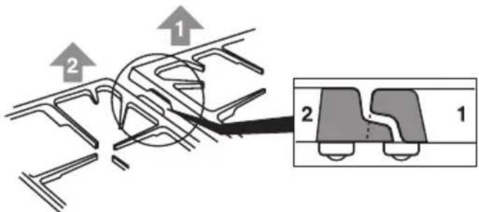
To permit thorough cleaning of the oven, the seal may be removed. Before removing the seal, take off the door as described above. Once the door has been taken off, lift the tabs at the corners as shown in the figure.
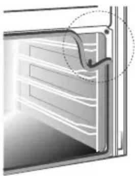
natural_image
Diagram of a door with a curved handle and internal panel lines, no text or symbols present11.4 Lubrication of gas taps
With time it may happen that the gas taps get blocked and hard to turn. Clean them inside and re-grease them. This operation must be done by a specialised technician.
- INSTRUCTIONS FOR SAFE AND PROPER USE
- Introduction
- INSTALLATION OF THE APPLIANCE
- Electrical connection
- 2.2
- Ventilation requirements
- 2.4
- Connecting to natural and LPG gas (Please see connection diagram)
- ADAPTATION TO DIFFERENT TYPES OF GAS
- Replacement of nozzles on the hob
- Arrangement of burners on cooking hob
- BURNERS
- FINAL OPERATIONS
- Adjustment of minimum for natural gas
- Regulation of minimum for LPG
- Positioning and levelling of the appliance
- Mounting the rear top upstand
- DESCRIPTION OF CONTROLS
- Front control panel
- DESCRIPTION OF SYMBOLS
- THERMOSTAT KNOB
- FUNCTION SWITCH KNOB
- COOKING HOB BURNER COMMAND KNOB
- Analog Programmer
- Timed cooking
- Delayed start cooking
- Manual mode cooking
- Electronic Analogue Clock (on some models only)
- LIST OF FUNCTIONS
- Setting the time
- Minute-minder
- Programming
- "DEMO" Function
- USE OF THE COOKING HOB
- Lighting of the cooking hob burners
- Practical advice for using the cooking hob burners
- Diameter of containers
- USE OF THE OVEN
- Warnings and general advice
- Oven Light
- Storage drawer
- AVAILABLE ACCESSORIES
- Accessories on Request
- COOKING HINTS
- Traditional cooking
- FUNCTION SWITCH
- THERMOSTAT SELECTOR SWITCH FROM 50° TO 250°C
- Hot-air cooking
- Grill cooking
- THERMOSTAT SWITCH AT MAXIMUM
- Hot-air grilling
- THERMOSTAT SWITCH FROM 50° TO 250°C
- Defrosting
- THERMOSTAT SWITCH IN POSITION 0
- Spit cooking
- THERMOSTAT SWITCH FROM 50° TO 200°C
- Keep the oven door closed during cooking.
- Recommended cooking table
- CLEANING AND MAINTENANCE
- Cleaning stainless steel
- Ordinary Daily Cleaning
- Food stains or residues
- Cleaning of cooking hob components
- Grids
- Burner caps, flame cap crowns and burners
- Ignition plugs and thermocouples
- Cleaning of the oven
- Self-cleaning liners
- Using the self-cleaning liners
- Looking after the self-cleaning liners
- Assembling the self-cleaning liners
- Door glass
- EXTRAORDINARY MAINTENANCE
- Replacement of light bulb
- Removing the door
- Oven door seal
- Lubrication of gas taps
Brand : SMEG
Model : A1WH-6
Category : Hot plate