
AVN363V - Security Camera LOGILINK - Free user manual and instructions
Find the device manual for free AVN363V LOGILINK in PDF.

| Product Type | Megapixel Outdoor IR Network Camera |
| Brand & Model | LogiLink AVN363V |
| Image Sensor | 1/3" MOS-Type |
| Resolution | 1280 x 1024 (SXGA), also supports SXVGA, 720P, VGA, QVGA |
| Lens | f4.0mm ~ f9.0mm, F2.0 (f=4mm) / F2.6 (f=9mm) |
| Viewing Angle | 75° ~ 36° |
| Minimum Illumination | 0 Lux (IR ON), 0.3 Lux (IR OFF) |
| IR LEDs | 56 units, effective range up to 30 meters (15 IPS) or 15 meters (30 IPS) |
| IR Cut Filter | Yes (IR Shift) |
| Video Compression | H.264 / MPEG-4 / MJPEG |
| Frame Rate | NTSC: 30 fps, PAL: 25 fps |
| Network | 10/100 Base-T Ethernet, supports DDNS, PPPoE, DHCP, NTP, SNTP, TCP/IP, ICMP, SMTP, FTP, HTTP, RTP, RTSP |
| ONVIF Compatible | Yes (AVN363V only) |
| Power Supply | AC 100V ~ 240V (±10%) |
| Power Consumption | 10W ~ 15W |
| IP Rating | IP67 (weatherproof) |
| Operating Temperature | -20°C ~ 40°C |
| Mobile Surveillance | iPad, iPod, iPhone, BlackBerry, Windows Mobile, Symbian, Android |
| Special Features | Face Tracking, Digital PTZ, Smart Zoom (optical), Smart Light Control, Motion Detection, Event Notification (Email, FTP, SMS), E-Map CMS support |
| Dimensions | Not specified |
| Weight | Not specified |
Frequently Asked Questions - AVN363V LOGILINK
User questions about AVN363V LOGILINK
0 question about this device. Answer the ones you know or ask your own.
Ask a new question about this device
Download the instructions for your Security Camera in PDF format for free! Find your manual AVN363V - LOGILINK and take your electronic device back in hand. On this page are published all the documents necessary for the use of your device. AVN363V by LOGILINK.
USER MANUAL AVN363V LOGILINK
Powerful Remote Surveillance
Distance makes no difference
To Our Valuable Customers,
Thank you for choosing this product. You'll be amazed by those useful functions this product provides, especially for the powerful mobile surveillance support.
Remote access via different platforms is widely supported:
a) For mobile platforms, iPhone®, BlackBerry®, Nokia® Symbian®, Windows® Mobile & Android™ are available with our self-developed and free program, EagleEyes, installed.
b) For web browsers, Internet Explorer®, Mozilla® Firefox®, Safari®, Google Chrome™ and Opera are supported.
c) Apple's media player, QuickTime®, is also one tool you can use.
To monitor and control multiple network devices, you can also install our free CMS software provided within the CD manual.
To know more about our mobile phone program, "EagleEyes", and where to download, please visit: http://www.eagleeyescctv.com
To know more about feature applications, please visit: www.eagleeyescctv.com/video
To know what's new for our products, please visit: www.eagleeyescctv.com/facebook
To seek for technical support, please contact: support@eagleeyescctv.com
To give us your precious suggestions and comments, please contact: marketing@eagleeyescctv.com
EagleEyes

MEGAPIXEL OUTDOOR IR NETWORK CAMERA SERIES
USER MANUAL
IMPORTANT SAFEGUARD

All lead-free products offered by the company comply with the requirements of the European law on the Restriction of Hazardous Substances (RoHS) directive, which means our manufacture processes and products are strictly “lead-free” and without the hazardous substances cited in the directive.
The crossed-out wheeled bin mark symbolizes that within the European Union the product must be collected separately at the product end-of-life. This applies to your product and any peripherals marked with this symbol. Do not dispose of these products as unsorted municipal waste. Contact your local dealer for procedures for recycling this equipment.
Disclaimer
We reserve the right to revise or remove any content in this manual at any time. We do not warrant or assume any legal liability or responsibility for the accuracy, completeness, or usefulness of this manual. The content of this manual is subject to change without notice.
Grounding
This is a Safety Class 1 Product (provided with a protective earthing ground incorporated in the power cord). The mains plug shall only be inserted in a socket outlet provided with a protective earth contact. Any interruption of the protective conductor inside or outside of the instrument is likely to make the instrument dangerous. Intentional interruption is prohibited.
Water & Moisture
Do not expose this product to dripping or splashing and that no objects filled with liquids, such as vases, shall be placed on the product.
Trademark Acknowledgements
iPhone® is the registered trademark of Apple Inc.
BlackBerry® and related trademarks, names and logos are the property of Research In Motion Limited and are registered and/or used in the U.S. and countries around the world. Used under license from Research In Motion Limited.
Android ™ is a trademark of Google Inc. Use of this trademark is subject to Google Permissions.
Microsoft, Windows, Internet Explorer, Mozilla Firefox, Google Chrome, QuickTime, Windows Mobile & Symbian mentioned in this document are the registered trademarks of their respective holders.
MPEG4 Licensing
THIS PRODUCT IS LICENSED UNDER THE MPEG4 VISUAL PATENT PORTFOLIO LICENSE FOR THE PERSONAL AND NON-COMMERCIAL USE OF A CONSUMER FOR (i) ENCODING VIDEO IN COMPLIANCE WITH THE MPEG4 VISUAL STANDARD ("MPEG-4 VIDEO") AND/OR (ii) DECODING MPEG4 VIDEO THAT WAS ENCODED BY A CONSUMER ENGAGED IN A PERSONAL AND NON-COMMERCIAL ACTIVITY AND/OR WAS OBTAINED FROM A VIDEO PROVIDER LICENSED BY MPEG LA TO PROVIDE MPEG4 VIDEO. NO LICENSE IS GRANTED OR SHALL BE IMPLIED FOR ANY OTHER USE. ADDITIONAL INFORMATION INCLUDING THAT RELATING TO PROMOTIONAL INTERNAL AND COMMERCIAL USES AND LICENSING MAY BE OBTAINED FROM MPEG LA, LLC. SEE HTTP://WWW.MPEGLA.COM.
GPL Licensing

This product contains codes which are developed by Third-Party-Companies and which are subject to the GNU General Public License (“GPL”) or the GNU Lesser Public License (“LGPL”).
The GPL Code used in this product is released without warranty and is subject to the copyright of the corresponding author.
Further source codes which are subject to the GPL-licenses are available upon request.
We are pleased to provide our modifications to the Linux Kernel, as well as a few new commands, and some tools to get you into the code. The codes are provided on the FTP site, and please download them from the following site or you can refer to your distributor:
http://download.dvrtw.com.tw/GPL/076D_Series/arm-linux-2.6.tar.gz
TABLE OF CONTENTS
1. OVERVIEW.... 1
1.1 Product features....1
1.2 Package content .... 1
1.3 Dimensions .... 1
1.4 Cable overview....1
2. BEFORE USING YOUR NETWORK CAMERA.... 3
3. ACCESSING THE CAMERA VIA VIDEO VIEWER 4
3.1 Installing Video Viewer .... 4
3.2 Accessing the camera .... 4
3.3 Control panel overview....5
3.3.1 Simplified version (Default) 5
3.3.2 Full function version 6
3.3.3 Main button overview 6
3.4 Frequently-used functions....7
3.4.1 Record....7
3.4.2 Playback....7
3.4.3 Firmware upgrade....8
3.4.4 E-Map....8
4. CAMERA CONFIGURATIONS VIA WEB BROWSER 13
4.1 Accessing the camera 13
4.2 Control panel overview....14
4.3 Face detection configurations 15
4.4 Digital PTZ (DPTZ) operations....16
4.5 System configuration menu....17
4.6 Network 18
4.6.1 Network 18
4.6.2 DDNS 18
4.6.3 SNTP 18
4.6.4 FTP 18
4.6.5 MAIL 19
4.6.6 SMS....19
4.6.8 Filter 20
4.6.9 UPnP 20
4.7 Camera 21
4.7.1 Camera....21
4.7.2 Preset....21
4.7.3 Cruise 22
4.7.4 Color....23
4.7.5 Time....24
4.7.6 Smart Zoom / Digital Smart Zoom....24
4.7.7 Calibration 25
4.7.8 Face Tracking....25
4.8 General 26
4.8.1 General....26
4.8.2 Server Log....26
4.8.3 Online 26
4.8.4 Account....27
4.8.5 Trigger 28
4.8.8 Upgrade....29
APPENDIX 1 PRODUCT SPECIFICATIONS....30
APPENDIX 2 API ID APPLICATION FOR SMS MESSAGING....31
APPENDIX 3 BIT RATE TABLE FOR REFERENCE ...... 33
1. OVERVIEW
1.1 Product features
● Powerful Remote Surveillance on Multiple Mobile Platforms
-- For mobile device platforms, iPad®, iPod®, iPhone®, BlackBerry®, Nokia® Symbian, Windows® Mobile & Android™ (with their built-in web browsers or EagleEyes)
-- For web browsers, Internet Explorer®, Mozilla Firefox®, Safari®, Google Chrome™ and Opera
-- For operating systems, Windows & Mac
-- For multiple device control, our CMS software, Video Viewer, is provided for free
● Free CMS software with E-Map for multiple devices control & surveillance
● Smart Light Control to avoid overexposure
● Motion detection & notification
● Excellent outdoor design with cable management and IP67
● Face Tracking support to zoom in on intruders with clear images
● 1.3 Megapixel for clear and accurate images
● Digital pan / tilt / zoom support for wide area monitoring
● (AVN363V / 362V Only) ONVIF standard supported to simplify system integration
1.2 Package content
| | Network camera
| | Installation Sticker
□ Installation Guide
☐ RJ45 cable extender adapter
□ CD-ROM disc (including user manuals & CMS software "Video Viewer")
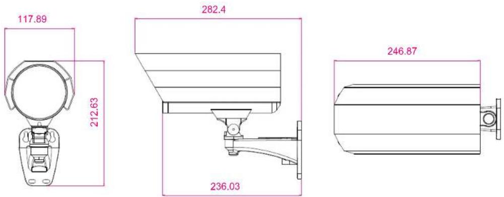
1.3 Dimensions
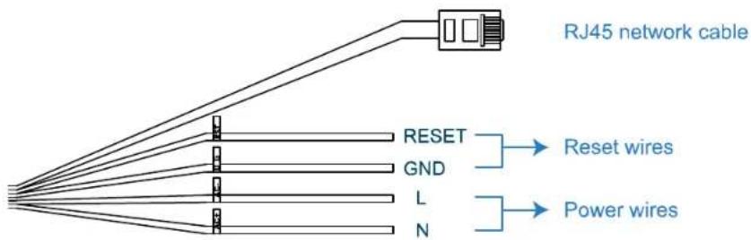
1.4 Cable overview
For AVN363 / 363V
flowchart
graph TD
    A["RJ45 network cable"] --> B["RESET"]
    A --> C["GND"]
    A --> D["L"]
    A --> E["N"]
    B --> F["Reset wires"]
    C --> G["Power wires"]
CABLE DESCRIPTION
| RJ45 network cable | Connect it to the supplied RJ45 cable extender adapter for cable extension, and prepare another RJ45 network cable with suitable length for your connection. |
| Reset wires | Remove the insulating coating of these two wires, and twist them together to reset default. This will reset all parameters, including the IP address to factory default settings.Note: Disconnect power before twisting these two wires together, and connect to power again for reset default. When the reset is done, disconnect these two wires. |
| Power wires Connect to AC power supply. For details, please refer to the installation guide. | |
For AVN362 / 362V
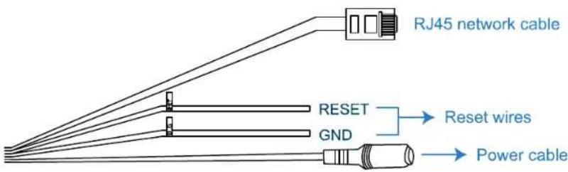
CABLE DESCRIPTION
| RJ45 network cable | Connect it to the supplied RJ45 cable extender adapter for cable extension, and prepare another RJ45 network cable with suitable length for your connection. |
| Reset wires | Remove the insulating coating of these two wires, and twist them together to reset default.This will reset all parameters, including the IP address to factory default settings.Note: Disconnect power before twisting these two wires together, and connect to power again for reset default. |
| Power cable Connect to | DC12V power supply. |
2. BEFORE USING YOUR NETWORK CAMERA
This network camera can be accessed via our supplied CMS software "Video Viewer", the web browser (such as "Microsoft Internet Explorer" or "Mozilla Firefox"), and smart phones with our self-developed program "EagleEyes" installed depending on different using situations.
Note: For details about accessing network cameras via smart phones, please refer to http://www.eagleeyescctv.com.
Before using the network camera, make sure:
1) You have installed the supplied CMS software, "Video Viewer", or a web browser.
2) You have configured the network settings, and the network connection is fine.
For Video Viewer installation, please refer to "3.1 Installing Video Viewer" at page 4.
For network configurations, please refer to your installation guide.
To check or configure up to 16 surveillance devices simultaneously with the record function, please use "Video Viewer".
For details about using Video Viewer, please refer to "3. ACCESSING THE CAMERA VIA VIDEO VIEWER" at page 4, and "4. CAMERA CONFIGURATION" at page 13.
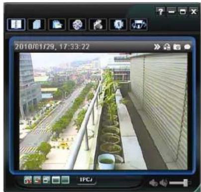
natural_image
Exterior view of a modern building with greenery and adjacent urban landscape (no signage)To check or configure this network camera only, it's recommended to use a web browser, such as "Microsoft Internet Explorer" or "Mozilla Firefox".
For details about using the web browser, please refer to "4. CAMERA CONFIGURATIONS VIA WEB BROWSER" at page 13.
3. ACCESSING THE CAMERA VIA VIDEO VIEWER
3.1 Installing Video Viewer
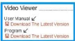
Step1: Place the supplied CD into your CD-ROM or DVD-ROM drive. The program will be automatically run.
Step2: Click "Program" in the "Video Viewer" section to install Video Viewer, or click "Download The Latest Version" under "Program" to download the latest version of Video Viewer from the Internet (if your PC is connected to Internet).
Step3: Follow the on-screen instructions to finish the installation. When the installation is completed, a shortcut icon "20 will be placed on your PC desktop."
3.2 Accessing the camera
Step1: Double-click "a" on your PC desktop to open Video Viewer. By defaults, the "Address Book" panel will be displayed on the right side of the control panel.
Step2: In "Address Book", click "☐" to key in the IP address, user name, password, and port number of the camera you intend to connect.
OR
Click "Q" → "G" to search the available IP address(es) of other camera(s) under the same domain as your PC's IP address. The found address(es) will be listed, and can be added into the address book by clicking "F".
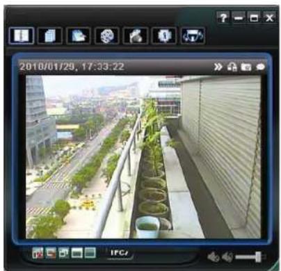
Step3: Double-click the IP address you just added into the address book to log in. The live view is displayed in the Video Viewer.
natural_image
Exterior view of a modern urban rooftop with greenery and adjacent buildings (no signage)3.3 Control panel overview
Two control panels are available and can be switched depending on your using habit.
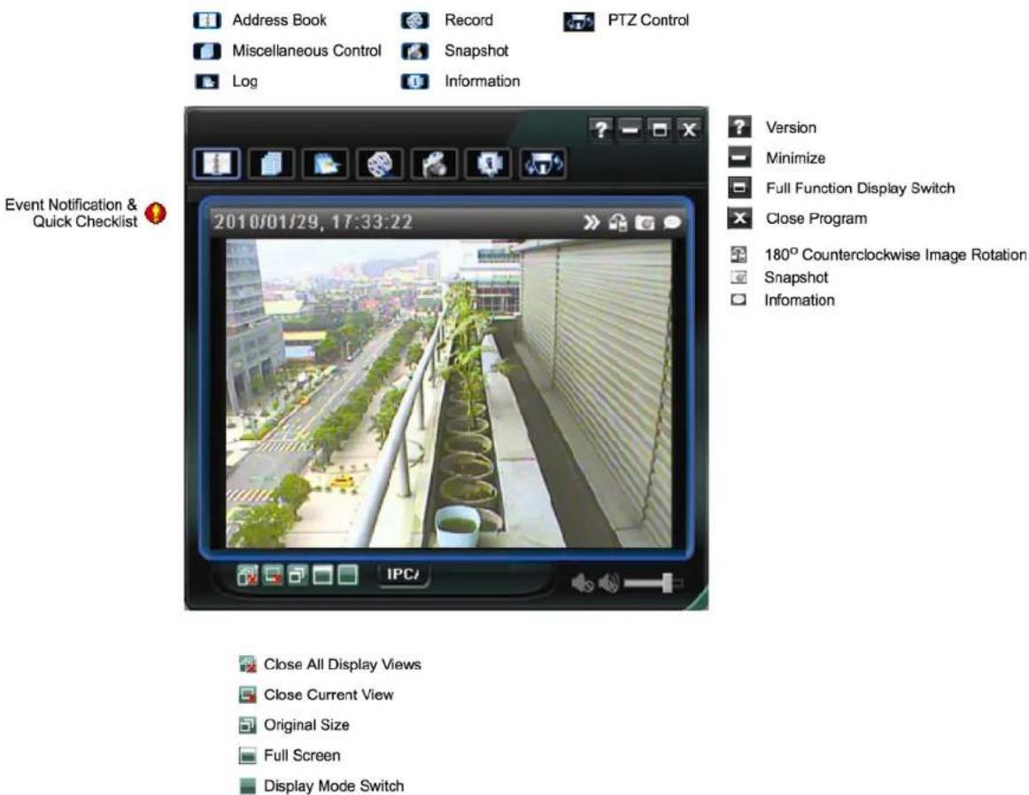
3.3.1 Simplified version (Default)
3.3.2 Full function version
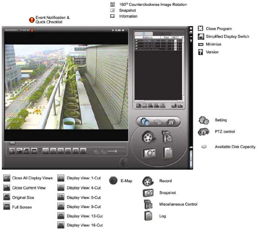
3.3.3 Main button overview
| Button | Function | Description | |||
| Simplified | Full Function | ||||
| Address Book | Click to show the predefined IP address(es). You can add, remove or search the IP address to log in the DVR remotely. | ||||
| Miscellaneous Control | Remote Config | Click to go to the detailed system configuration. For details, please refer to "4. CAMERA CONFIGURATIONS VIA WEB BROWSER" at page 13. | |||
| Record Setting | Click to go to the detailed record setting. For details, please refer to "3.4.1 Record" at page 7. | ||||
| Custom Setting | Click to choose the language of this program, or set the password when activating this program. The changes will take effect when this program is closed and executed again. | ||||
| Log | Click to view all event and recording logs, search the desired log(s) by date, or playback the recording of the selected log. | ||||
| Record / Record Stop | Click to start / stop the manual recording.The record button will be disabled when the reserved disk capacity set in "Record Setting" is larger than the current disk capacity. For details, please refer to "3.4.1 Record" at page 7. | ||||
| Snapshot | Click to take a snapshot of the current view. The snapshot will be saved in the path you specified in "Record Setting". | ||||
| Information | Click to show the current network connection details. | ||||
| PTZ Control | Click to enter the DPTZ control panel. | ||||
3.4 Frequently-used functions
3.4.1 Record
To record remotely, click "☐" or "☐" → "☐" to go to the "Record Setting" page.
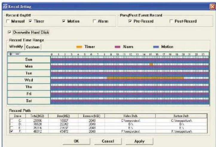
In the "Record Setting" page, you can set the following items:
- Record type
• Pre- / post-event record - Record time setting
- Record path
Note: The record function will be disabled when the reserved disk capacity in "Reserved(MB)" is larger than the current disk capacity in "Free(MB)".
When “Manual” is checked, click “☐” or “☐” on the main control panel to start the manual recording immediately, and the recordings will be saved in the location specified in “Record Path”.
When "Motion" and / or "Alarm" are checked, the recording function will be enabled for any motion or alarm event, and the recordings will be saved in the location specified in "Record Path".
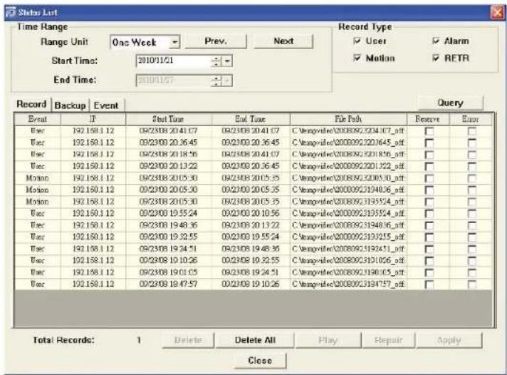
3.4.2 Playback
To play a recording, click “” or “”, and select the “Record” tab. A list of all the recordings will be shown by defaults, and you can also sort out the logs you want to speed up the search time.
3.4.3 Firmware upgrade
This function is used when users need to upgrade the network camera for function scalability.
Note: Before using this function, make sure you have the correct upgrade files provided by your installer or distributor.
Step1: Click "☐", and select the IP address of your network camera in the address book.
Step2: Click "to show the upgrade page, "Update Server".
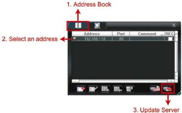
Step3: Click "Add" to browse to the upgrade files.
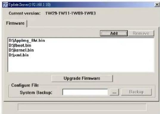
Step4: Click "Upgrade Firmware" to start firmware upgrade.
Note: It takes a few minutes to finish the upgrade process. Do not disconnect the power during firmware upgrade, or the upgrade may be failed. The camera will reboot after the upgrade.
Step5: Select the IP address of the camera and click again to check if the firmware is upgraded.
3.4.4 E-Map
Video Viewer is also a Central Management System (CMS) software, which allows network device control & management for up to 16 devices simultaneously.
Note: Before using this function, make sure Video Viewer is connected to all the devices (up to 16) you want to monitor.
E-Map is ONLY available when the control panel is switch to the full function version.
How to add an E-Map group
STEP1: In the simplified version, click "☐" to switch the control panel to the full function version, and click "☐" to enter the E-Map page as follows.
Note: To know where the buttons are, please refer to "3.3.1 Simplified version (Default) at page 5, and "3.3.2 Full function version" at page 6.
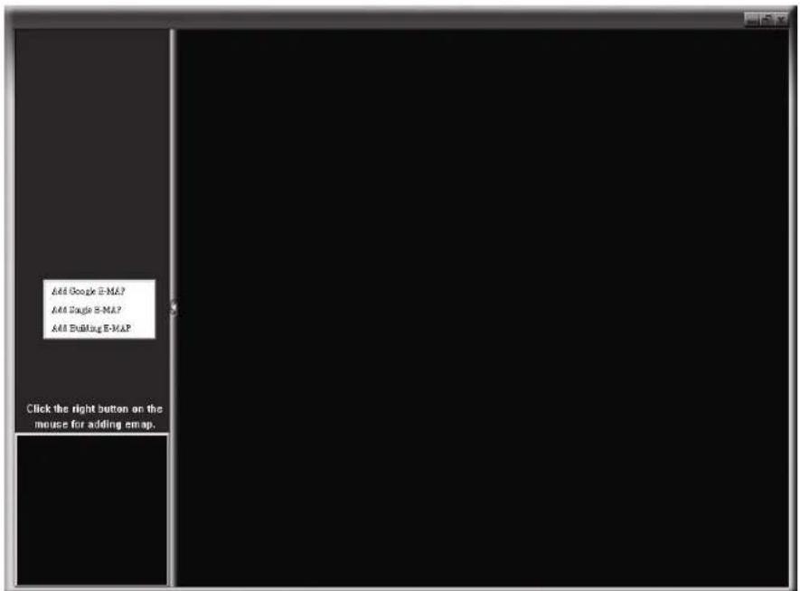
STEP2: Right-click to show the shortcut menu on the top-left panel, and select the E-Map group you want to add. There are three E-Map groups you can add: Google E-MAP, Single E-MAP, and Building E-MAP.

How to add a Google E-Map group:
1 Enter the name of this Google E-Map group.
2 Enter a specific address or landmark, and click "Search". OR Move to the map and drag to the location you want.
3 Click and drag the IP address to where it's located in the current level.
4 Click "Apply" to save and finish.
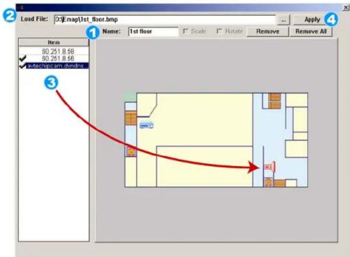
How to add a single E-Map group:
1 Enter the name of this single E-Map group.
2 Click “...” to browse the map file in BMP or JPEG.
3 Click and drag the IP address to where it's located in the current level.
4 Click "Apply" to save and finish.
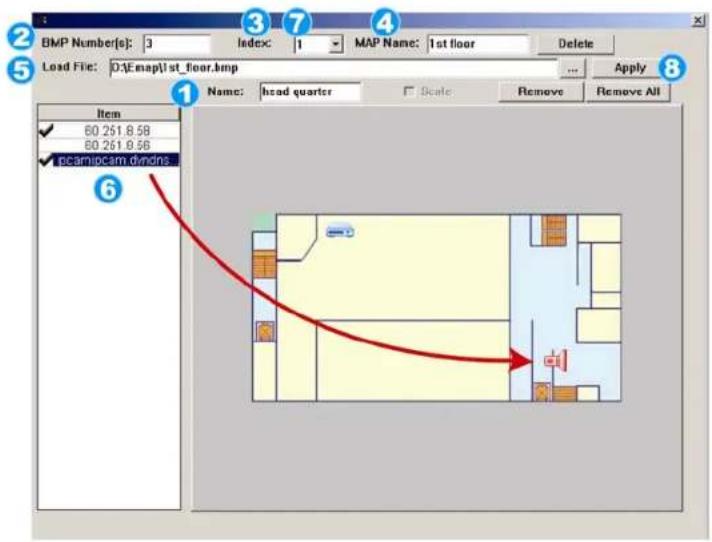
How to add a building E-Map group:
1 Enter the name of this building E-Map group.
2 Enter the total levels of this building.
3 Select the level of the building from the drop-down list.
4 Enter the name of the level.
⑤ Click “...” to browse the map file in BMP or JPEG.
6 Click and drag the IP address to where it's located in the current level.
7 Go back to STEP 3 to select other level of the building, and repeat from STEP 3 to 6 until the setup for all levels are finished.
8 Click "Apply" to save and finish.
STEP3: When the E-Map group is created, you will see the tree on the top-left panel, showing all the devices you've added to this group.
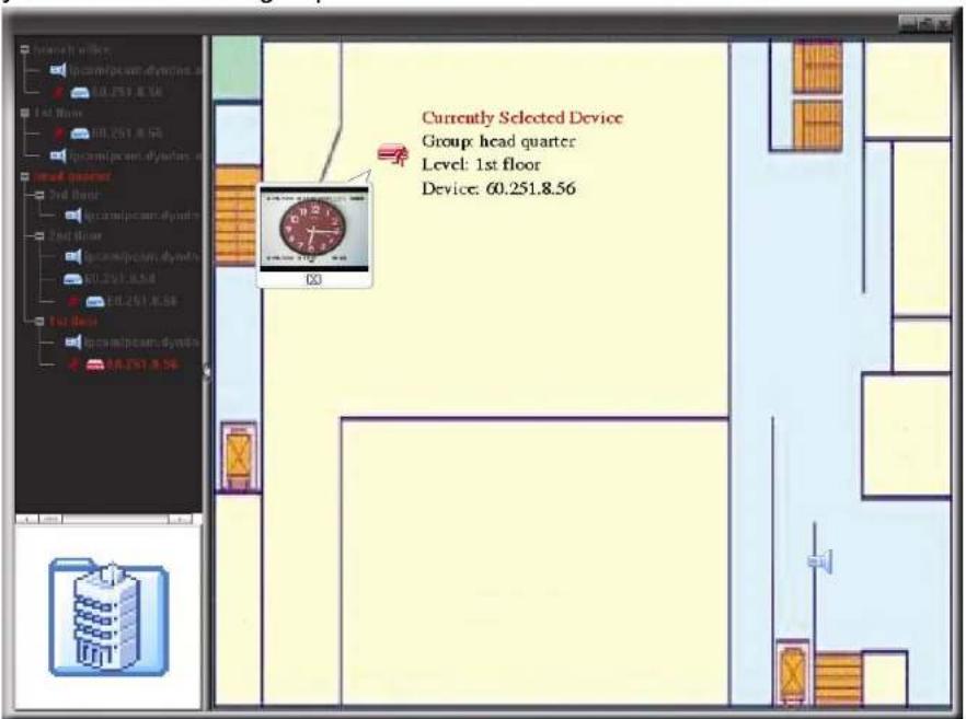
| Icon | Description |
| The connected device is camera. When it's selected, it will become red. | |
| The connected device is DVR. When it's selected, it will become red. | |
| For any motion or alarm event, it will appear on the screen to catch your attention.To know what's happening quickly, double-click the device icon on the E-Map to show the live view. |
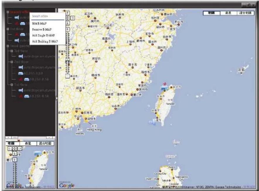
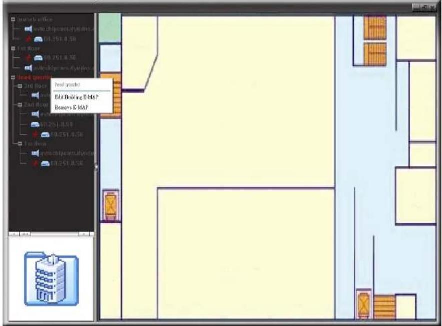
How to edit / remove an existing E-Map group
For Google E-Map Group
Right-click on the group name to show the shortcut menu list, and select "Edit E-MAP" or "Remove E-MAP" as needed.
You can also add a single E-Map group (Add Single E-MAP) or Building E-Map group (Add Building E-MAP) into the existing Google E-Map group.
Right-click on the group name to show the shortcut menu list, and select "Edit E-MAP" or "Remove E-MAP" as needed.
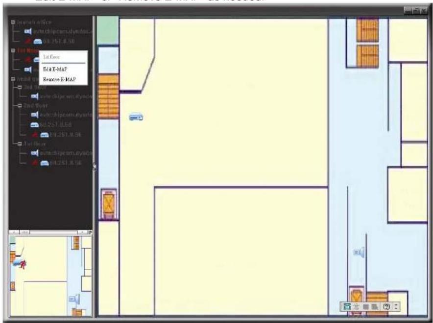

For Building E-Map Group
Right-click on the group name to show the shortcut menu list, and select "Edit Building E-MAP" or "Remove E-MAP" as needed.
4. CAMERA CONFIGURATIONS VIA WEB BROWSER
Users can also access the network camera via a web browser, such as Microsoft Internet Explorer, Mozilla Firefox, Google Chrome and Safari.
Note: It's recommended to consult with your installer before changing system configurations.
Note: You need to be the supervisor to enter the system configuration page. If not, please re-log into the camera with the supervisor user level.
However, the web browser is only available for single device access. If users want to access more than two devices through one interface, it's recommended to use our supplied CMS software, Video Viewer. For details, please refer to "3. ACCESSING THE CAMERA VIA VIDEO VIEWER" at page 4.
Before using the network camera, make sure you have configured the network settings and have the IP address, user name and password used for accessing the camera in hand. If not, please refer to the installation guide.
4.1 Accessing the camera
Step1: Open your web browser, and key in http://ipaddress:portnum in the URL address box.
For example, for IP address 60.121.46.236 and port No. 888, please key in "http://60.121.46.236:888" into the URL address box, and press "Enter".
Step2: In the login page, key in the user name and password, and enter the security code from the image below if any. Then, click "LOGIN".
Step3: The wizard is then started.
- To skip the wizard and directly access the camera live view, click "Close".
- To directly access the camera live view without starting the wizard for the login next time, check "Do not start wizard at login".
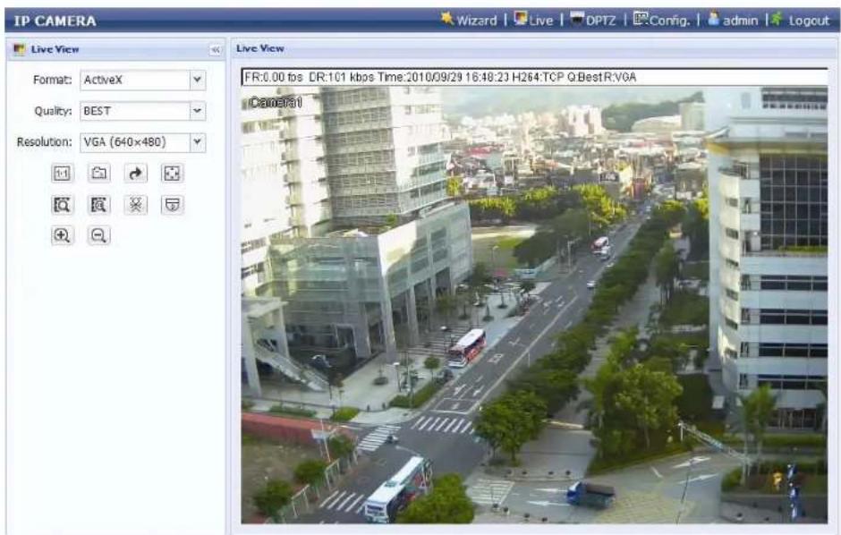
Step4: When the login is successful, the live view is shown.
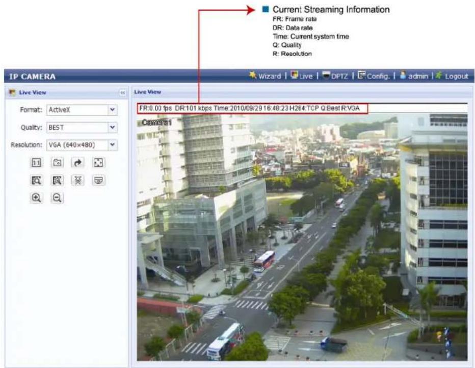
4.2 Control panel overview
| Function Icon User Level Description | |||
| Configuration Page: Supervisor / Power User | |||
| Live |  | Switch to the live view page. | |
| DPTZ | Switch to the DPTZ configuration page.For details, please refer to "4.4 Digital PTZ (DPTZ) operations" at page 16. | ||
| Config. |  | Switch to the system configuration page, and the functions available for "Supervisor" and "Power User" are different.For details, please refer to "4.5 System configuration menu" at page 17. | |
| Format | -- | Supervisor / Power User / Normal User / Guest | Select the web transmission format from the drop-down list:■ ActiveX■ QuickTimeFor users using Mozilla Firefox or Google Chrome, only "QuickTime" is selectable.QuickTime is Apple Inc.'s multimedia software. You need to have QuickTime installed in your operating system before selecting "QuickTime". When it is selected, you will be promoted to enter the user name and password to access the camera. |
| Quality -- Supervisor / Power User / Normal | Click & drag the slider to select the video quality:BASIC / NORMAL / HIGH / BEST. | ||
| Resolution | -- Supervisor / Power User / Normal | Select the image resolution from the drop list:■ SXGA (1280 x 1024) ■ SXVGA (1280 x 960)■ 720P (1280 x 720) ■ VGA (640 x 480)■ QVGA (320 x 240) | |
| Live View Size: | Supervisor / Power User | ||
| Normal Size |  | The current live view size is the same as the selected resolution. | |
| Fit to screen | [004H] | Resize the selected resolution to fit into the live view size.This icon appears only when the selected resolution is larger than the current live view size. | |
| Scale | [0xH2] | Click and hold the movable square on the left bottom corner of the live view to moveThis icon appears only when the selected resolution is larger than the current live view size. | |
| CIF Resize |  | Resize the QVGA resolution to fit into the live view size.This icon appears only when the selected resolution is QVGA (CIF) than the current live view size. | |
| Snapshot | [XYY] | Supervisor / Power User / Normal User | Click to take a snapshot of the current view, and save to the location specified in "Config." → "Camera" → "Camera" → "Snapshot Path". |
| Flip | [SY78] | Supervisor / Power User / Normal User | Click to rotate the image 180irc counterclockwise when necessary. |
| Full Screen | Supervisor / Power User / Normal User | Click to display the image in full screen.To exit the full screen mode, press “Esc” on your keyboard. | |
| Smart Zoom | Supervisor / Power User / Normal User | Click to activate the optical (AVN363 / 363V) / digital (AVN362 / 362V) smart zoom function. | |
| Smart Zoom 10 | Supervisor / Power User | For AVN363 / 363V onlyClick to enable consecutive Smart Zoom for 10 minutes and disable the idle mode. Con80secutive Smart Zoom will be off after 10 minutes, and auto Smart Zoom will be on instead. | |
| Face Tracking | Supervisor / Power User / Normal User | Click to enable the face tracking function.Note: This function is disabled when the stream format is set to “Multi-Mode”. | |
| DPTZ | Supervisor / Power User / Normal User | Click to enable digital PTZ functions. | |
| Zoom in / out | Supervisor / Power User / Normal User / Guest | For AVN363 / 363V onlyClick to zoom in / out the current image. | |
**Face Tracking, DPTZ & Smart Zoom can't be activated simultaneously.
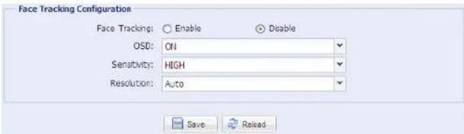
4.3 Face tracking configurations
Face tracking is used to especially zoom in on the intruder's face, easy for everyone to identify.
Note: When this function is enabled, DPTZ, Smart Zoom, and optical zoom are not allowed to use.
Note: Face tracking is not supported when the stream format is set to Multi-Mode, and this menu will not be shown in the configuration page.
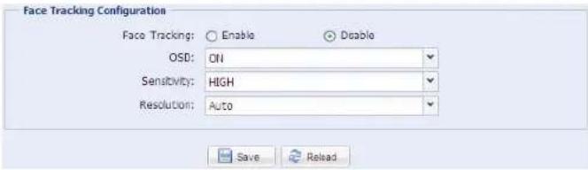
STEP1: Click "Config." → "Camera" → "Face Tracking" to enter the configuration page.
STEP2: Select and set as described below:
| ITEM DESCRIPTION | |
| Face Tracking | Select “Enable” to activate or “Disable” to deactivate this function. |
| OSD | Select “ON” to display the following status messages on the live view:FACE STANDBY: This function is activated and ready to use. |
| FACE TRACKING: This function is tracking. | |
| FACE ZOOM IN / OUT: This function is zooming on the face for tracking / zooming out when the tracking object leaves the surveillance area. | |
| Sensitivity | Set the tracking sensitivity from HIGH / MEDIUM / LOW. |
| Resolution | Set the resolution for face tracking from Auto / VGA / QVGA. |
STEP3: When all the configurations are done, click "Save" to save your changes, and click "Live" on the top to return to the live view.
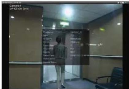
4.4 Digital PTZ (DPTZ) operations
This fixed network camera type has PTZ capability, i.e. digital PTZ (hereafter called "DPTZ"), for wide area monitoring.
Note: When this function is enabled, Face Tracking, Smart Zoom, and optical zoom are not allowed to use.
STEP1: Click "DPTZ" to show the DPTZ control panel.

STEP2: Select the functions when needed:
| ICON FUNCTION DESCRIPTION | ||
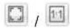 | Fit to screen /Restore to original size | There are several monitor resolutions available. When the selected resolution is out of your current live view support, a part of your surveillance area might get covered on the screen, and you need to manually move on the screen to check the covered part. |
| This is used to scale the selected resolution to fit in the current live view size. | ||
| This is used to restore the scaled live view resolution to its original size. | ||
 | Take snapshots | Click to take a snapshot of the current view, and save to the location specified in "Config." → "Camera" → "Camera" → "Snapshot Path". |
 | Enable Auto mode | Click to activate the auto mode of the camera. The auto mode could be "Sequence" or "Auto Pan" specified in "Config." → "Camera" → "Cruise" → "Active Mode".Note: This function is available only when DPTZ is enabled. |
| Sequence: Move to several preset points accordingly and regularly specified in "Config." → "Camera" → "Cruise" → "Active Mode" → "Sequence".Note: Preset points are set in "Config." → "Camera" → "Preset". | ||
| Auto Pan: Pan automatically and horizontally. | ||
 | Enable DPTZ | Click to activate the digital PTZ function. When this function is enabled, the following operations are available:Auto modeMove up / down / left / right after digital zoom-in. |
 | Zoom in / out | Click to zoom in / out the image.For AVN362 / 362V, they're available only when DPTZ is enabled.For AVN363 / 363V, they're optical zoom-in / out; when is selected, they'll switch to digital zoom-in / out. |
| [X654] | Max. zoom in / out | Click to zoom in / out the image.For AVN362 / 362V, they're available only when DPTZ is enabled.For AVN363 / 363V, they're optical max. zoom-in / out; when is selected, they'll switch to digital max. zoom-in / out. |
4.5 System configuration menu
Click "Config." to enter the configuration page.
Note: You need to be "Supervisor" or "Power User" to enter the system configuration page, and the functions available for these two user levels are different. If you're not either of these two user levels, please re-log into the camera with one of them.
The functions are categorized into three menus: Network, Camera and General.
For details about "Network", please refer to "4.6 Network" at page 18.
For details about "Camera", please refer to "4.7 Camera" at page 21.
For details about "General", please refer to 4.8 General" at page 26.
Main Menu Sub-Menu Reference
| Network Network Configure network settings. | ||
| DDNS Enter DDNS information when the network type is PPPOE or DHCP. | ||
| SNTP Synchronize your camera time with the networked computer systems. | ||
| FTP | Enter the FTP information for event notifications when "FTP" is chosen in "General" > "Trigger". | |
| Enter Email information for event notifications when "Email" is chosen in "General" > "Trigger". | ||
| SMS | Enter text messaging information for SMS notifications when "SMS" is chosen in "General" → "Trigger". | |
| Filter Choose to permit or block the IP address(es) which can access this camera. | ||
| Camera | Camera | 1. Set the camera title.2. Specify the snapshot path.3. Select the streaming settings based on your network environment. |
| Preset Set the preset points for the DPTZ function. | ||
| Cruise Set the cruise mode when the auto mode is enabled: Sequence or Auto Pan. | ||
| Color | Adjust the color performance. | |
| Time | Set daylight saving time and the current time. | |
| Smart Zoom or Digital Smart Zoom | "Smart Zoom" is for AVN363 / 363V; "Digital Smart Zoom" is for AVN362 / 362V.Set the sensitivity and standby interval. | |
| Calibration | This function is available for AVN363 / 363V only.Adjust the focus of each focal length. | |
| Face Tracking | Hidden only when the steam format is set to "Multi-Mode".Configure the parameters for face tracking. | |
| General | General | 1. Select the language of the web browser.2. Check the MAC address of the camera.3. Lock camera access after the specified time. |
| Server Log | Available for Supervisor only.Check the system event logs. | |
| Online | Available for Supervisor only.Check the current online user(s). | |
| Account | Available for Supervisor only.1. Create a new user account with different access privilege.2. Modify or delete an existing user account. | |
| Trigger | 1. Enable / disable face and motion detection.2. Set the motion detection area.3. Select the event notification method. | |
| Upgrade | Check the current firmware version and upgrade. | |
4.6 Network
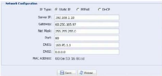
4.6.1 Network
You can set the network configuration of the network camera depending on your network type.
For details, please refer to your installation guide.
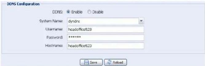
4.6.2 DDNS
Select "On" when the selected network type in "Network" is "PPPOE" or "DHCP". For details, please refer to the installation guide.
4.6.3 SNTP
SNTP (Simple Network Time Protocol) is used to synchronize your camera time with the networked computer systems.
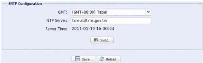
| Function Description | |
| GMT Once users choose the time zone, the network camera will adjust the local area time of the system automatically. | |
| NTP Server Simply use the default SNTP server (For example, tock.stdtime.gov.tw) or change to another server with which users are familiar. | |
| Sync Click and the network camera will synchronize the time with the network time. | |
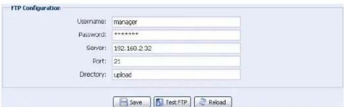
4.6.4 FTP
Enter the detailed FTP information and click "Save" to confirm. The information you set here will be applied when "FTP" is selected in "General" > "Trigger".
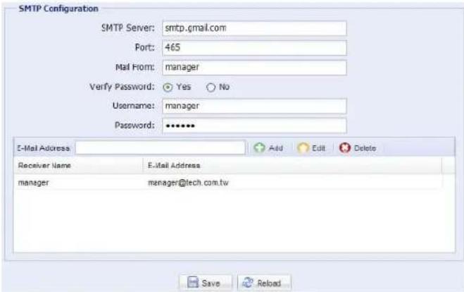
4.6.5 MAIL
Enter the detailed e-mail information and click "Save" to confirm. The information you set here will be applied when "Email" is selected in "General" → "Trigger".
Function Description
| SMTP Server Enter the SMTP server address provided from your e-mail system supplier. | |
| Port | Enter the port number provided from your e-mail system supplier. If this column is left blank, the e-mail server will use port 25 to send e-mails. |
| Mail From Enter the entire mail address to ensure e-mails will not be blocked by SMTP. | |
| Verify Password | Some mail servers are required to verify the password. Please enter the "user name" and "password". |
| E-Mail Address List Add the e-mail address(s) of the assigned recipient(s). | |
4.6.6 SMS
Note: Before using this function, you need to apply an API ID from the mobile messaging company, Clickatell, and you will be charged starting from the 11 th message. For details, please refer to "APPENDIX 2 API ID APPLICATION FOR SMS MESSAGING' at page 31.
Enter the detailed information needed for text messaging, and click "Save" to confirm. The information you set here will be applied when "SMS" is selected in "General" → "Trigger".
![SMS Configuration System: clickatell Username: toch Password: ********** API ID: 3281378 Recipient: +386912665475 Transfer Interval: 15 Message: [192.168.1.10] unauthorised access Minute(s) Reset Counter Include Hostname or IP Save Test Reload](/content/2026/05/1141460/images/c41f0c712542a54845bf58069d9368599f244951bb7911dfb0c10394a1937d73.jpg)
Function Description
| System The text messaging service provider is Clickatell. | |
| User name / Password | Enter the account user name and password you created in Clickatell. |
| API ID Enter the API ID you applied from Clickatell. | |
| Recipient | Click "Add" to enter the phone number, including the country code, to receive the text message. Five sets of phone numbers are allowed. |
| Transfer Interval | Set the interval time in minutes between two-message sending.The options are 0, 15, 30 & 60. |
Function Description
| Reset Counter | Click to restart the text messaging, and the SMS will be sent after the specified time interval since you click this button. |
| Message | Enter the text content (up to 70 characters) you want to send with the text message. |
| Test SMS | To know whether your SMS setting is correct, click this button to immediately send a SMS to your phone.Note: This testing is not free and you will be charged for SMS sending base on your local rate. |
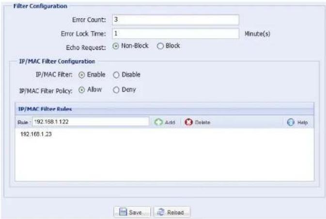
4.6.8 Filter
Choose to permit or block the IP address(es) which can access this camera, and click "Save" to confirm.
Function Description
■ Filter Configuration
| Error Count | Set the maximum count for login failure. When the maximum count is reached, the IP address trying to access the network camera will be locked. |
| Error Lock Time | Set the lock time in minutes when the maximum count of error login for an IP address is reached. |
| Echo Request | Select "Non-Block" to allow other users to use the ping command to detect the IP address of your network camera, or "Block" to deny the ping command request. |
| ■ IP/MAC Filter Configuration | |
| IP/MAC Filter Choose | to enable or disable the filter function. |
| IP/MAC Filter Policy If | "Enable" is selected, choose whether you want to permit (Allow) or block (Deny) the IP address list below. |
| ■ IP/MAC Filter Rules | |
| Rule | To add an item to the IP address list, key in the IP address in "Rule", and click "Add".To remove an existing item in the IP address list, click the item you want to remove, and click "Delete". |
4.6.9 UPnP
"UPnP" stands for "Universal Plug and Play", which allows devices to connect seamlessly in the home and corporate environments and simplify installation of computer components.
Check "Enable" to allow the network camera to be detected among devices within the same network area, and set the identification name of the camera in "Friendly name".
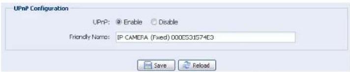
When this function is activated, the other PC within the same domain as this camera will be able to search this camera in "Network Neighbor" with the identification name set in "Friendly name". Double-click it to quickly open the web browser for camera access.
4.7 Camera
4.7.1 Camera
Adjust the camera parameters if necessary.
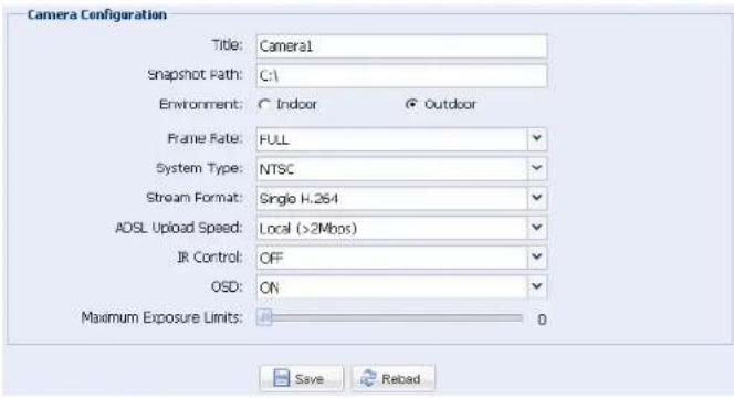
| Item Description | |
| Title Enter the title for the camera with up to 15 alphabetic characters. | |
| Snapshot Path Specify the location to save the snapshot pictures. | |
| Environment | Select the current environment for the camera to automatically adjust itself to produce the images suitable for the selected environment. |
| Frame Rate | The frame rate allowed to each viewer can be adjusted to adapt to the bandwidth on the network.Set the desired image frequency to the maximum (FULL) or to a specified frame rate (1/2; 1/3; 1/4; 1/5; 1/10; 1/15).The actual frame rate depends on the actual network connection, and may be lower than the specified one. |
| System Type It shows the current system type: NTSC or PAL. | |
| Stream Format Select the streaming format to H.264 / MPEG-4 / Motion JPEG. | |
| ADSL Upload Speed | Select your Internet upload speed, and the system will automatically adjust your data flow.The options are: Local (>2Mbps) / 2M (2000Kbps) / 1M (1000Kbps) / 640Kbps / 512 Kbps / 256Kbps / 128 Kbps / 64Kbps |
| IR Control | Select “AUTO” to automatically enable IR LEDs at night or in the dark environment, or “OFF” to disable this function. |
| OSD | Select “ON” to show the camera title on the live view, or “OFF” to hide the camera title. |
| Maximum Exposure Limits | This function is used to extend the exposure time for clearer images when the light is not sufficient.Select 1 ~ 5 to extend the exposure time based on your current light condition. The larger the value, the longer the exposure time, and the less the fps.0 means function off. |
4.7.2 Preset
Note: Before using this function, make sure the DPTZ function is enabled.
You can set new preset points (up to 16) or check existing points here.
How to set a new preset point
Step1: Click DPTZ icon.
Step2: Click to where you want to see, and you'll get a 5x zoom-in image. To slightly zoom out, draw a square from the bottom right to top left, and you'll get a 3x image. Draw the square again and you'll return to the original size.
Step3: In "Current Position", give a name to this point, and click "Add".

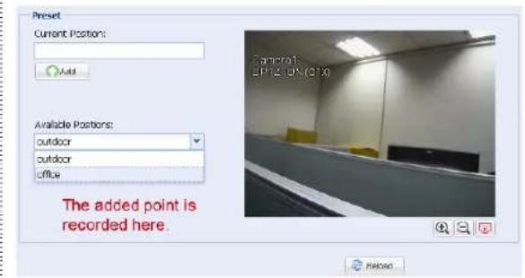
How to check an existing preset point
In "Available Positions", select the name of the point you want to check from the drop-down list, and click "Goto".
You will see the camera view on the right side moving to the point it's recorded.
How to delete an existing preset point
In "Available Positions", select the name of the point you want to check from the drop-down list, and click "Remove".
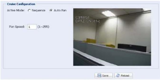
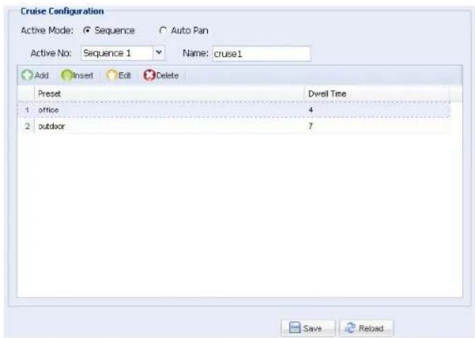
4.7.3 Cruise
Note: Before using this function, make sure you have finished setting several preset points.
Here defines how the auto mode of the camera is going to work when is selected: Sequence or Auto Pan.
Auto Pan
When "Auto Pan" is selected here and 🔒 is clicked on the live view page, the camera will start panning.
Sequence
When "Sequence" is selected here and is clicked on the live view page, the camera will start patrolling each preset point defined in "Sequence".
Step1: Click "Add" to choose a preset point from the drop-down list, and select the duration to stay at this point from 1 \~ 60 minutes.
Then, click "Save" to confirm.
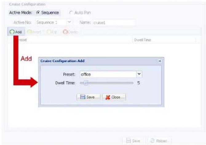
Step2: Click "Add" again to add more preset points. When all the points are added, click "Save" to confirm.
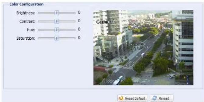
4.7.4 Color
Adjust the color performance from Brightness, Contract, Hue and Saturation. Click and drag the slider to preview the color change on the right side of this page and adjust the image color.
To restore the default values, click "Back to Default".
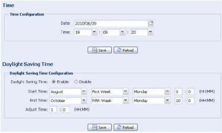
4.7.5 Time
Set daylight saving time and the current time, and click "Save" to confirm.
Function Description
■ Time Configuration
| Date | Set the current date. |
| Time | Set the current time. |
| ■ Daylight Saving Time Configuration | |
| Daylight Saving Time | Specify whether to use daylight saving time (Enable / Disable). |
| If this function is enabled, set the time period (Start Time / End Time), and adjust the daylight saving time in hours (Adjust Time). | |
4.7.6 Smart Zoom / Digital Smart Zoom
Note: "Smart Zoom" is available for AVN363 / 363V; "Digital Smart Zoom is available for AVN362 / 362V.

Column Description
| Smart Zoom To switch this function on or off, select "Enable" or "Disable".Or, it's also available to click ☑ to enable / disable this function on the live view panel. | |
| Detection* Select to set a specific detection area for this function. | |
| Sensitivity Select the digital smart zoom sensitivity (HIGH / MEDIUM / LOW) | |
| Stand-by Interval Select the stand-by interval (Short / Normal / Long). |
* Aavailable for AVN362 / 362V only.
Note: This function is available for AVN363 / 363V only.
Go to this page to adjust the focus in each focal length.
When you finish the calibration, select "Storage" to save, or "Back to Default" to discard.
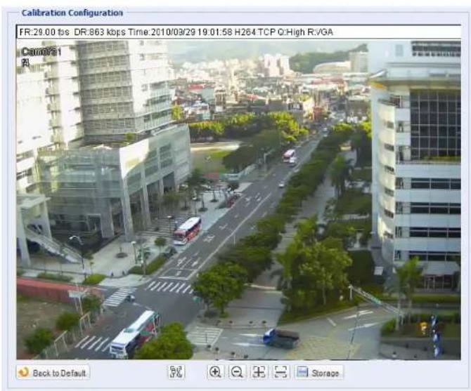
| Icon Function Description | ||
| Auto Calibration Click to start calibrating the focus in each zoom ratio. | ||
| Manual Calibration | ||
| Zoom in / out | Clickto select the focal length you want to adjust. | |
| Focus in / out | Click/to adjust the focus for the selected focal length. | |
4.7.8 Face Tracking
Configure the parameters for face tracking.
Note: Face tracking is not supported when the stream format is set to Multi-Mode, and will not be shown in the configuration page.
| Function Description | |
| Face Tracking | Select “Enable” to activate or “Disable” to deactivate this function. |
| OSD | Select “ON” to display the following status messages on the live view:FACE STANDBY: This function is activated and ready to use. |
| FACE TRACKING: This function is tracking. | |
| FACE ZOOM IN / OUT: This function is zooming on the face for tracking / zooming out when the tracking object leaves the surveillance area. | |
| Sensitivity | Set the tracking sensitivity from HIGH / MEDIUM / LOW. |
| Resolution | Set the resolution for face tracking from Auto / VGA / QVGA. |
4.8 General
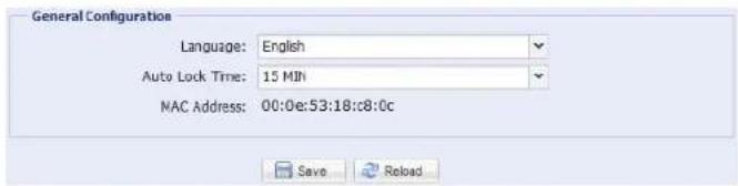
4.8.1 General
In "General", you can select the UI language to English or Chinese, and check the MAC address of your camera.
To lock camera access when it's not used after the specified time, select "5 MIN", "15 MIN" or "30 MIN" from the drop-down list of "Auto Lock Time", or select "NEVER" to disable this function.
Note: When the camera access is locked after the specified time, to resume camera access, please enter the password.
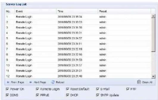
4.8.2 Server Log
Note: This function is available only for "Supervisor".
To quickly search the system logs you want by event type, click "Prev. Page" or "Next Page" to find the logs you want, or check the event type(s) and click "Reload" to start searching.
To clear all system event logs, click "Clear All".
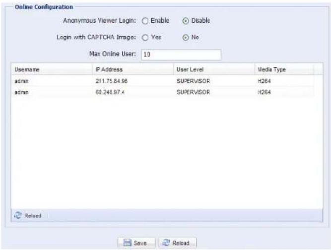
4.8.3 Online
Note: This function is available only for "Supervisor".
You can check the current online user(s) with respective online information. To refresh the list, click "Reload".
To allow anonymous login, select "Enable" in "Anonymous Viewer Login".
To disable image code verification at login, select "No" in "Login with CAPTCHA Image".
4.8.4 Account
Note: This function is available only for "Supervisor".
You can create a new account with different user access privilege, or delete or modify an existing account setting.
How to create a new account
Step1: Click "New", and fill in the following columns.
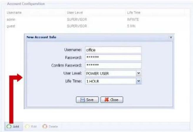
| Column Description | |
| User Name | Set a user name that will be used for camera access. The user name allows up to 16 alphanumeric characters. |
| Password Set the password that will be used for remote login. The password allows up to 16 alphanumeric characters. | |
| Confirm Password Enter the password again to confirm. | |
| User Level | Set the security level of an account to give the permission to control different functions. There are four user levels: SUPERVISOR, POWER USER, NORMAL USER and GUEST. |
| Life Time | Select how long this account is allowed to stay online (1 MIN / 5 MIN / 10 MIN / 1 HOUR / 1 DAY / INFINITE) |
Step2: Then, click "Save" to save your setting and create a new account.
How to modify or delete an existing account
Step1: Select the account you want to modify or delete.
Step2: To modify the account, click "Edit" to change the settings, and click "Save".
To remove the account, click "Delete".
Note: It's not allowed to remove an account when there's only one account in the account list.
4.8.5 Trigger
You can set the motion or face detection and select the notification function.
Note: Motion detection is not supported when the stream format is Motion JPEG.
Note: Face detection is not supported when the stream format is set to Multi-Mode.
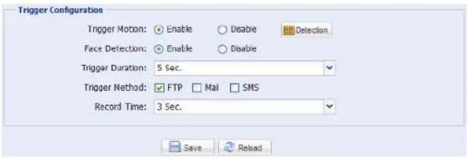
Trigger Setting
In this section, you can select to enable or disable motion & face detection.
| Item Description | |
| Motion | Select to enable or disable the motion detection function. |
• Motion Detection Area SettingWhen “Enable” is selected, click “Detection” to enter the motion detection area setting page as follows: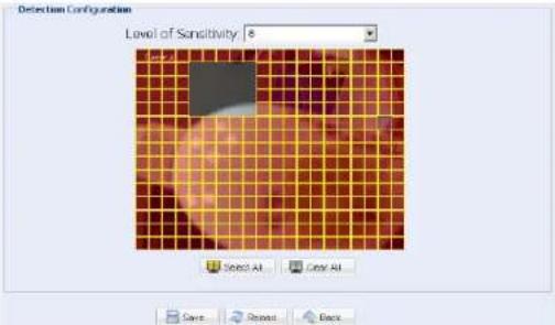 | |
| Level of Sensitivity:Set the detection sensitivity from 0 ~ 9.Area Setting:Set the motion detection area by selecting the area grids with your mouse. Pink grids represent the area that is not being detected while the transparent grids are the area under detection. You can set multiple areas under detection.Click “Clear All” to set the whole area undetected.Click “Select All” to set the whole area under detection. | |
| Trigger Duration Set the duration time for trigger recording (5 / 10 / 20 / 40 seconds). | |
◆ Notification Setting
In this section, you can select to enable E-mail / FTP / SMS notification when a motion event happens.
| Item Description | |
| Method • Email | When this option is checked, the network camera will upload the captured video clip to the assigned e-mail address(s) once motion recording happened. • FTP When this option is checked, the network camera will upload the captured video clip to the specified FTP site once motion recording happened. • SMS When this option is checked, the network camera will send a text message to the specified mobile phone number once a motion detection event occurs. For details, please refer to “4.6.6 SMS” at page 19. |
| Trigger Duration | Set the duration when a motion or face detection event occurs (5 / 10 / 20 / 40 seconds). |
| Record Time Set the record time of the notification video clip (1 ~ 5 seconds). | |
4.8.8 Upgrade
This function is used when users need to upgrade the network camera for function scalability.
Note: Before using this function, make sure you have the correct upgrade files provided by your installer or distributor.
Note: For system upgrade from a web browser, it only supports upgrading one file at a time. To upgrade all files, you need to start from Step1 again when one file is upgraded. If you want to upgrade all files at a time, please use our supplied CMS software, Video Viewer. For details, please refer to "3.4.3 Firmware upgrade" at 8.
Step1: Click "☐" to browse to where you save the upgrade files, and select one of them.
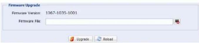
Step2: Click "Upgrade" to start system upgrading.
Note: It takes a few minutes to finish the upgrade process. Do not disconnect the power during firmware upgrade, or the upgrade may be failed. The camera will reboot after the upgrade.
APPENDIX 1 PRODUCT SPECIFICATIONS
| AVN363 | AVN363V | AVN362 | AVN362V | |
| ■ Network | ||||
| Network Compression H.264 / MPEG4 / MJPEG | ||||
| LAN Port YES | ||||
| LAN Speed 10/100 Based-T Ethernet | ||||
| Supported Protocols | DDNS, PPPoE, DHCP, NTP, SNTP, TCP/IP, ICMP, SMTP, FTP, HTTP, RTP, RTSP | |||
| ONVIF Compatible | NO | YES | NO | |
| Video Resolution SXGA,SXVGA,720P, VGA,QVGA | ||||
| Frame Rate NTSC:30, PAL:25 | ||||
| Number of Online Users | 10 | |||
| Security | Multiple user access levels with password | |||
| Web management | (1) Web browsers, such as Internet Explorer, Mozilla Firefox, Google Chrome, & Safari for single device access, or (2) Free CMS software, Video Viewer, for up to 16 network cameras control simultaneously | |||
| ■ Camera | ||||
| Image Sensor | 1/3" MOS-Type Image Sensor | |||
| Pixels | 1280 (H) x 1024 (V) | |||
| Min Illumination | 0 Lux (11m IR ON) / 0.3 Lux (IR OFF) | 0 Lux (11m IR ON) / 0.2 Lux (IR OFF) | ||
| Shutter Speed | At 60 fps: 1/60s to 1/60000s | |||
| S/N Ratio | More than 48dB (AGC off) | |||
| Lens | f4.0mm ~ f9.0mm | f6.0mm | ||
| F-number | F2.0(f=4mm) / F2.6(f=9mm) | F1.8 | ||
| Viewing Angle | 75°~36° | 62° | ||
| IR LED | 56 units | |||
| IR Effective Range | 15 meters (30 IPS) / 30 meters (15 IPS) | Up to 25 meters | ||
| IR Shift | YES | |||
| White Balance | ATW | |||
| IP Rating | IP67 | |||
| Power Source (±10%) | AC100V ~ 240V | DC12V / 1.5A | ||
| Power Consumption (±10%) | 10W ~ 15W | -- | ||
| Current Consumption (±10%) | -- | 1000 mA | ||
| Operating Temperature | -20°C~40°C | |||
| ■ Others | ||||
| Mobile Surveillance | iPad, iPod, iPhone, BlackBerry, Windows Mobile, Symbian & Android | |||
| Motion Detection | YES | |||
| Smart Light Control | YES | |||
| Digital Smart Zoom | YES | |||
| Digital Pan / Tilt / Zoom | YES | |||
| Face Detection | YES | |||
| Event Notification | FTP and Email | |||
| Minimum Web Browsing Requirements | · Pentium 4 CPU 1.3 GHz or higher, or equivalent AMD · 256 MB RAM · AGP graphics card, Direct Draw, 32MB RAM · Windows 7, Vista & XP, DirectX 9.0 or later · Internet Explorer 7.x or later | |||
** The specifications are subject to change without notice.
** Dimensional tolerance: ± 5mm
APPENDIX 2 API ID APPLICATION FOR SMS MESSAGING
To allow the camera automatically sending a text message when an event happens, you need to apply an API ID from Clickatell, one mobile messaging company, first.
Note: The SMS messaging is not totally free. You will be charged starting from the 11th message.
Please follow the steps below for application.
Step1: Go to http://www.clickatell.com/login.php. In "New Customers", select "Clickatell Central (API)" from the drop-down list.
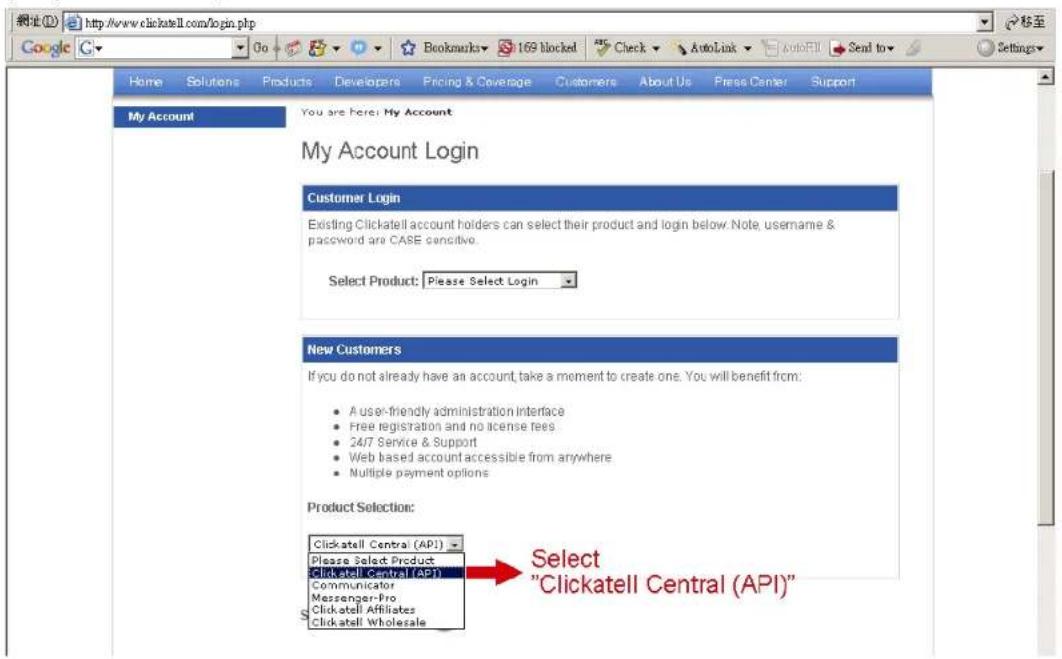
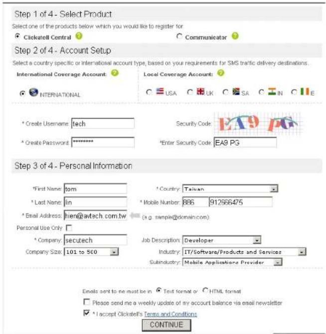
Step2: Fill in your information to create an account, and click "CONTINUE".
Note: Note down the user name and password, and the mobile phone number you specified here for SMS notification setting later.
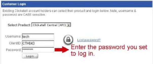
Step2: When the account is created, the system will automatically send an Email to your specified Email address and ask you to activate your account.
Click the link in the Email to complete account activation, and enter the login page as follows. Enter the password you set, and click "Login".
My Account Login
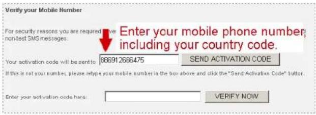
Step3: Enter the mobile phone number (including your country code) you want the text message to be sent, and click "SEND ACTIVATION CODE". The system will send an activation code to that number for verification.
Check if you receive a text message from Clickatell.
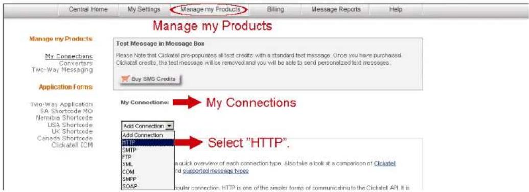
Step4: Go back to Clickatell, and click the tab "Manage my Products". Then, select "HTTP" from the drop-down list "My Connections".
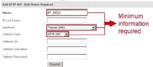
Step5: In "Add HTTP API", enter a descriptive name for this service, and make sure the dial prefix is correct and callback type is "HTTP GET". Then, click "Submit".
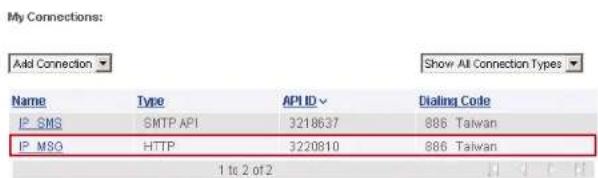
Step5: You will get an API ID as follows.
Note: Note down the API ID for SMS notification setting later.
APPENDIX 3 BIT RATE TABLE FOR REFERENCE
The data below is for reference only.
The bit rates listed here may vary depending on the resolution, image quality & frame rate you choose, the complexity of your monitoring area, and how often the moving objects show in your monitoring area.
Testing Environment
■ Place: Office Entrance
■ Network translation: H.264
■ Camera type: Megapixel camera
Static: No one coming in and out Dynamic: One or two people coming in and out
| Resolution Quality Frame Rate | (Dynamic) kbps (Static) kbps | |||
| SXGA | Best | FULL | 3253 | 3216 |
| High | 2375 | 2160 | ||
| Normal | 1571 | |||
| Basic | 1465 | |||
| VGA | Best | 2010 | 1261 | |
| High | 1042 | 1034 | ||
| Normal | 685 | 572 | ||
| Basic | 457 | 350 | ||
| QVGA | Best | 646 | 366 | |
| High | 482 | 350 | ||
| Normal | 302 | 286 | ||
| Basic | 168 | 161 | ||
| SXGA | Best | 1/4 | 1163 | 1076 |
| High | 989 | 715 | ||
| Normal | 855 | 534 | ||
| Basic | 719 | 443 | ||
| VGA | Best | 789 | 571 | |
| High | 451 | 447 | ||
| Normal | 349 | 237 | ||
| Basic | 217 | 165 | ||
| QVGA | Best | 269 | 147 | |
| High | 182 | 131 | ||
| Normal | 164 | 113 | ||
| Basic | 97 | |||
1266 873
71
| Resolution Quality Frame Rate | (Dynamic) kbps (Static) kbps | |||
| SXGA | Best | 1/15 | 581 | |
| High | 405 | |||
| Normal | 487 | |||
| Basic | 337 | |||
| VGA | Best | 358 | ||
| High | 201 | |||
| Normal | 180 | |||
| Basic | 92 | 15 | ||
| QVGA | Best | 111 | 84 | |
| High | 99 | 68 | ||
| Normal | 97 | |||
| Basic | 58 | 42 | ||
- Powerful Remote Surveillance
- Distance makes no difference
- MEGAPIXEL OUTDOOR IR NETWORK CAMERA SERIES
- IMPORTANT SAFEGUARD
- Disclaimer
- Grounding
- Water & Moisture
- Trademark Acknowledgements
- MPEG4 Licensing
- GPL Licensing
- TABLE OF CONTENTS
- OVERVIEW.... 1
- BEFORE USING YOUR NETWORK CAMERA.... 3
- ACCESSING THE CAMERA VIA VIDEO VIEWER 4
- CAMERA CONFIGURATIONS VIA WEB BROWSER 13
- APPENDIX 1 PRODUCT SPECIFICATIONS....30
- APPENDIX 2 API ID APPLICATION FOR SMS MESSAGING....31
- APPENDIX 3 BIT RATE TABLE FOR REFERENCE ...... 33
- OVERVIEW
- Product features
- Package content
- Dimensions
- Cable overview
- BEFORE USING YOUR NETWORK CAMERA
- ACCESSING THE CAMERA VIA VIDEO VIEWER
- Installing Video Viewer
- Accessing the camera
- Control panel overview
- Simplified version (Default)
- Full function version
- Main button overview
- Frequently-used functions
- Record
- Playback
- Firmware upgrade
- E-Map
- How to add a Google E-Map group:
- How to add a single E-Map group:
- How to add a building E-Map group:
- How to edit / remove an existing E-Map group
- For Google E-Map Group
- For Building E-Map Group
- CAMERA CONFIGURATIONS VIA WEB BROWSER
- Accessing the camera
- Control panel overview
- Face tracking configurations
- Digital PTZ (DPTZ) operations
- System configuration menu
- Network
- Network
- DDNS
- SNTP
- FTP
- SMS
- Filter
- Function Description
- UPnP
- Camera
- Camera
- Preset
- How to set a new preset point
- How to check an existing preset point
- How to delete an existing preset point
- Cruise
- Auto Pan
- Sequence
- Color
- Time
- Smart Zoom / Digital Smart Zoom
- Column Description
- Face Tracking
- General
- General
- Server Log
- Online
- Account
- How to create a new account
- Trigger
- Trigger Setting
- ◆ Notification Setting
- Upgrade
- APPENDIX 1 PRODUCT SPECIFICATIONS
- APPENDIX 2 API ID APPLICATION FOR SMS MESSAGING
- APPENDIX 3 BIT RATE TABLE FOR REFERENCE
- Testing Environment
Brand : LOGILINK
Model : AVN363V
Category : Security Camera