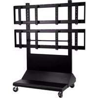
100013262 - Television NEC - Free user manual and instructions
Find the device manual for free 100013262 NEC in PDF.


| Product Type | Mobile Display Cart / Stand |
| Brand | NEC |
| Model | 100013262 |
| Maximum Load Capacity | 500 lbs (227 kg) |
| Material | Steel, powder-coated finish |
| Color | Black (typical) |
| Dimensions (Approx.) | Height: 60–72 in, Width: 40–50 in, Depth: 30–40 in (adjustable) |
| Weight | Approx. 80–100 lbs (empty) |
| Wheel Size | 5" swivel casters (4 included) |
| VESA Compatibility | Up to 600x400 mm (via adapter brackets) |
| Number of Displays Supported | Up to 4 (typical multi-panel) |
| Height Adjustment | Yes, via horizontal rails and knobs |
| Tilt / Angle Adjustment | Yes, fine-tuning knobs |
| Cable Management | Yes, with mesh sleeve and cable ties |
| Assembly Required | Yes, detailed instructions included |
| Certifications | ETL, TÜV (typical) |
| Warranty | 5 years (typical NEC warranty) |
Frequently Asked Questions - 100013262 NEC
User questions about 100013262 NEC
0 question about this device. Answer the ones you know or ask your own.
Ask a new question about this device
Download the instructions for your Television in PDF format for free! Find your manual 100013262 - NEC and take your electronic device back in hand. On this page are published all the documents necessary for the use of your device. 100013262 by NEC.
USER MANUAL 100013262 NEC
natural_image
Technical line drawing of a multi-panel modular device with wheels and structural panels (no text or symbols)
Maximum Load Capacity 500 lbs (227 kg)
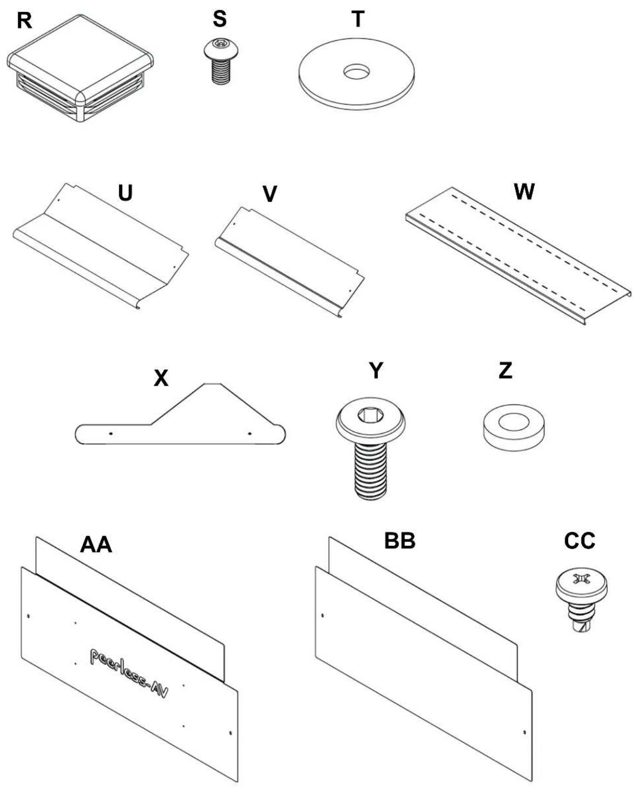
| PARTS LISTDescription Qty. Part # | |
| A vertical support 2 145-1389 | |
| B adapter brackets 8 145-1711 | |
| C horizontal support 3 124-1852 | |
| D horizontal rail 2 145-1238 | |
| E 5" caster | 4 600-0026 |
| F 1/4" flat washer | 56 540-9440 |
| G M8 x 25 mm phillips screw | 16 520-1031 |
| H 5/16 flat washer | 16 540-9406 |
| I 5/16 split washer | 16 540-9405 |
| J 1/4-20 x 3.5" hex head screw | 56 520-1656 |
| K 1/4-20 nylock nut 56 530-9413 | |
| L .38 OD x .06 LG nylon washer | 16 590-2233 |
| M 18" mesh sleeve | 4 600-1014 |
| N M8 x 16 mm phillips screw | 16 520-9257 |
| O M6 x 12 mm phillips screw | 16 520-1128 |
| P 4 mm allen wrench | 4 560-9646 |
| Q cable tie | 8 560-9711 |
| R tube cap | 2 590-1289 |
| S M5 x 10 mm socket pin screw (not used) | 8 520-1164 |
| T #14 fender washer (not used) | 16 540-1008 |
| U front bottom cover | 1 145-1364 |
| V back bottom cover | 1 145-1363 |
| W component shelf | 1 145-1361 |
| X side cover | 2 145-1362 |
| Y decorative screw | 12 520-2326 |
| Z spacer | 4 |
| AA front top cover | 1 145-1388 |
| BB back top cover | 1 145-1368 |
| CC self-drilling phillips screw | 3 520-1320 |

natural_image
Technical illustration of mechanical components including a frame, wheel, and threaded fastener (no text or symbols)

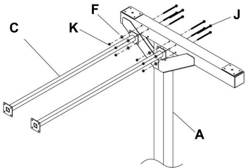
Assembling Cart
1 Attach two horizontal supports (C) to vertical support (A) using eight 1/4-20 x 3.5" hex head screws (J), 1/4" SAE washers (F) and 1/4-20 nylock nuts (K).
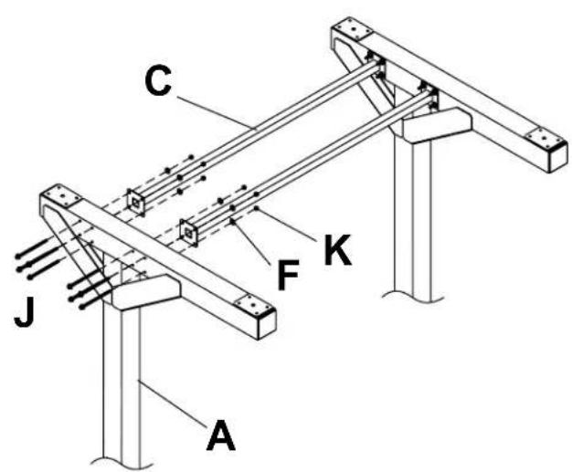
2 Attach horizontal supports (C) to second vertical support (A) using eight 1/4-20 x 3.5" hex head screws (J), 1/4" SAE washers (F) and 1/4-20 nylock nuts (K).
3 Attach horizontal support (C) to vertical supports (A) using eight 1/4-20 x 3.5" hex head screws (J), 1/4" SAE washers (F) and 1/4-20 nylock nuts (K).


Attach four swivel casters (E) to vertical supports (A) using sixteen M8 x 25 mm pan phillips screws (G), split washers (I) and 5/16" SAE flat washers (H).


Determine position of horizontal rails (D) using the formula below.
- Locate the position of the lower horizontal rail (D) and attach to vertical supports (A).
- Use display height to determine location of upper horizontal rail (D),
NOTE: Lowest horizontal rail (D) position shown in detail 1.
NOTE: Horizontal rails (D) must be secured using sixteen 1/4-20 x 3.5" hex head screws (J).

5 of 10
ISSUED: 03-08-11 SHEET #: 125-9195-5 09-20-12

Attach horizontal rails (D) onto vertical supports (A) using sixteen 1/4-20 x 3.5" hex head screws (J), 1/4" SAE washers (H) and 1/4-20 nylock nuts (K) as shown in detail 1. Make sure that horizontal rails (D) are level then tighten all 1/4-20 x 3.5" hex head screws (J). Place two tube caps (R) into tops of vertical supports (A) as shown in detail 2. NOTE: horizontal rails (D) must be secured using sixteen 1/4-20 x 3.5" hex head screws (J).

CABLE MANAGEMENT

Run display cables though top and bottom openings in vertical supports (A) as shown.
NOTE: Display cables can be covered using 18" mesh sleeve (M) before securing.
Display cables can be secured to horizontal rails (D) using eight cable ties (Q) as needed through slots in horizontal rails (D).


Attach adapter brackets (B) to back of display using four M6 x 12 mm phillips screws (O) with nylon shoulder washer (L), or four M8 x 15 mm phillips screws (N) as shown below.

Adapter Bracket Placement Detail

Use detail 3 to figure adapter bracket (B) placement.


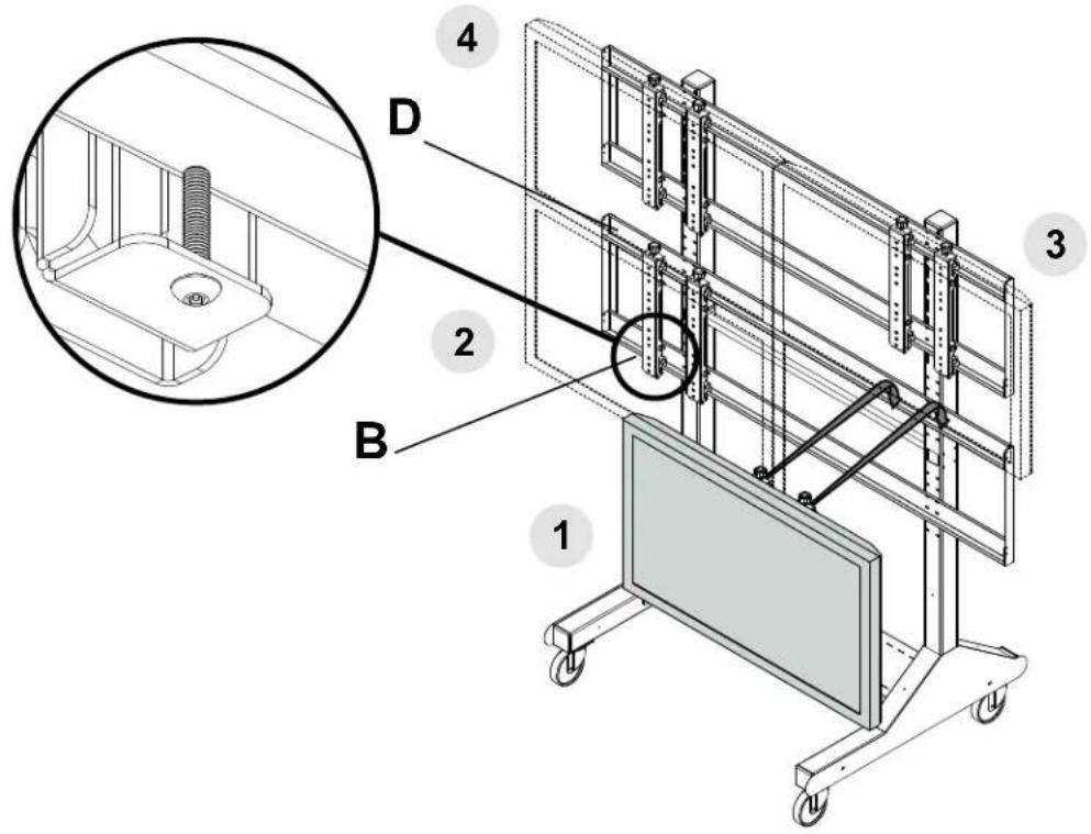
Hook display and adapter brackets (B) onto horizontal rail (D) as shown below. NOTE: Hang displays in sequenced order.
NOTE: Once display is located in desired position, tighten security screws as shown in detail 4.
Attaching Component Shelf (Optional)

Fasten component shelf (W) onto horizontal support (C) using three self-drilling phillips screws (CC) as shown below.

Adapter Bracket Adjustment

Use legend below to determine position of display.
NOTE: Each knob can be adjusted independently for fine tuning angle adjustments.

Turn knobs CLOCKWISE to raise display height.
Turn knobs COUNTER-CLOCKWISE to lower display height.

Turn knobs CLOCKWISE to push out display.
Turn knob COUNTER-CLOCKWISE to pull in display.
UP DOWN IN OUT


Attaching Covers

NOTE: Position bottom front and back covers first
Position front bottom cover (U). Secure covers in place using four decorative screws (Y) as shown below. Position back bottom cover (V). Secure covers in place using four decorative screws (Y) as shown below. Position front top cover (AA). Secure covers in place using four decorative screws (Y) as shown below. Position back top cover (BB). Secure covers in place using four decorative screws (Y) as shown below. Optional: Front top cover (AA), and back top cover (BB) can be interchanged.
Attach two retaining spacers (Z), and decorative screws (Y) to side cover (X) as shown in detail 5. Attach side covers to vertical supports (A).


Brand : NEC
Model : 100013262
Category : Television