SVRK-9U-S - Uncategorized Auray - Free user manual and instructions
Find the device manual for free SVRK-9U-S Auray in PDF.


| Product Type | Uncategorized Electronic Device |
| Brand | Auray |
| Model | SVRK-9U-S |
| Dimensions (approx.) | 30 x 20 x 15 cm |
| Weight | 1.5 kg |
| Power Supply | AC 100-240V, 50/60Hz |
| Power Consumption | 60W |
| Main Functions | Basic operation as per manual |
| Maintenance & Cleaning | Wipe with a soft, dry cloth |
| Safety Precautions | Read user manual before use |
| Spare Parts & Repairability | Contact Auray support for spare parts |
| Warranty | Standard manufacturer warranty |
| Country of Origin | China |
| Certifications | CE, RoHS |
Frequently Asked Questions - SVRK-9U-S Auray
User questions about SVRK-9U-S Auray
0 question about this device. Answer the ones you know or ask your own.
Ask a new question about this device
Download the instructions for your Uncategorized in PDF format for free! Find your manual SVRK-9U-S - Auray and take your electronic device back in hand. On this page are published all the documents necessary for the use of your device. SVRK-9U-S by Auray.
USER MANUAL SVRK-9U-S Auray
(4/6/9/12U) (Shallow/Deep)
Owner's Manual
natural_image
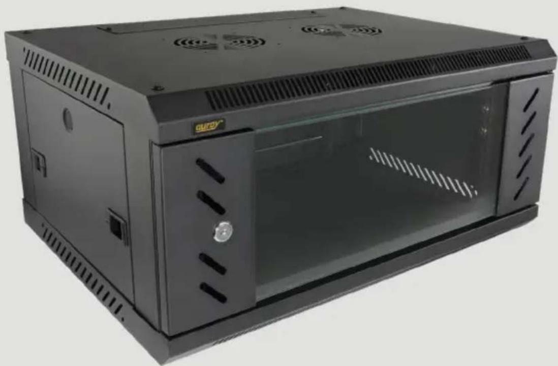
Exterior view of a black server rack unit with ventilation grilles and ventilation grilles (no visible text or symbols)Thank you for choosing Auray.
Auray's server racks come in shallow and deep 4-, 6-, 9-, and 12-space configurations. Vented top and side panels promote airflow throughout the rack, and all racks are configured to accept optional rack fans. Front and back rack rails are included to install rack shelves and large devices that need four-corner support. Each model can be used as stand-alone unit or wall mounted via the rack's key holes or an included wall-mount bracket. Side panels and a locking door are included to limit access to the installed devices.
Precautions
- Please read and follow these instructions, and keep this manual in a safe place.
- Use only parts provided by the manufacturer.
- Do not exceed the weight capacity of this product.
- This product is for indoor use only.
- Make sure the mounting surface and the wall attachments can support the weight of the rack and installed equipment.
- Make sure everything is secure before proceeding.
- Make sure that this product is intact and that there are no missing parts.
- Keep this product away from water and any flammable gases or liquids.
- Do not stack the rack on top of another rack.
- This rack requires an earth ground connection. Do not use this product without an earth ground connection.
- Do not overtighten or improperly thread any of the threaded fittings.
- All images are for illustrative purposes only.
Overview
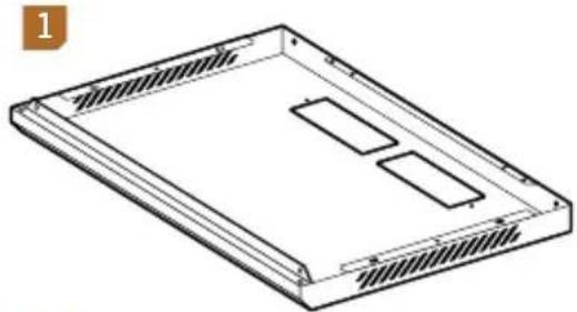
Bottom panel 1
Top panel 2
Side bracket (×2) 3
Side panel (×2) 4
Right angle vertical rail ( × 2)
5
Left angle vertical rail (×2)
6
Front door 7
Back panel 8
Cable port cover (×2) 9
Wall mount bracket 10
natural_image
Isometric line drawing of a rectangular electronic device casing with internal compartments (no text or symbols)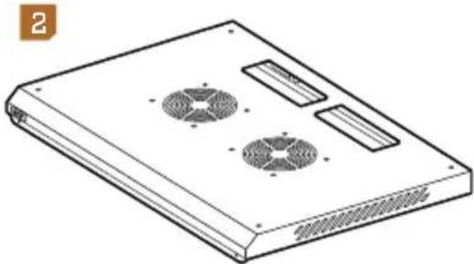
natural_image
Line drawing of a flat electronic device with four circular fans and ventilation slots (no text or symbols)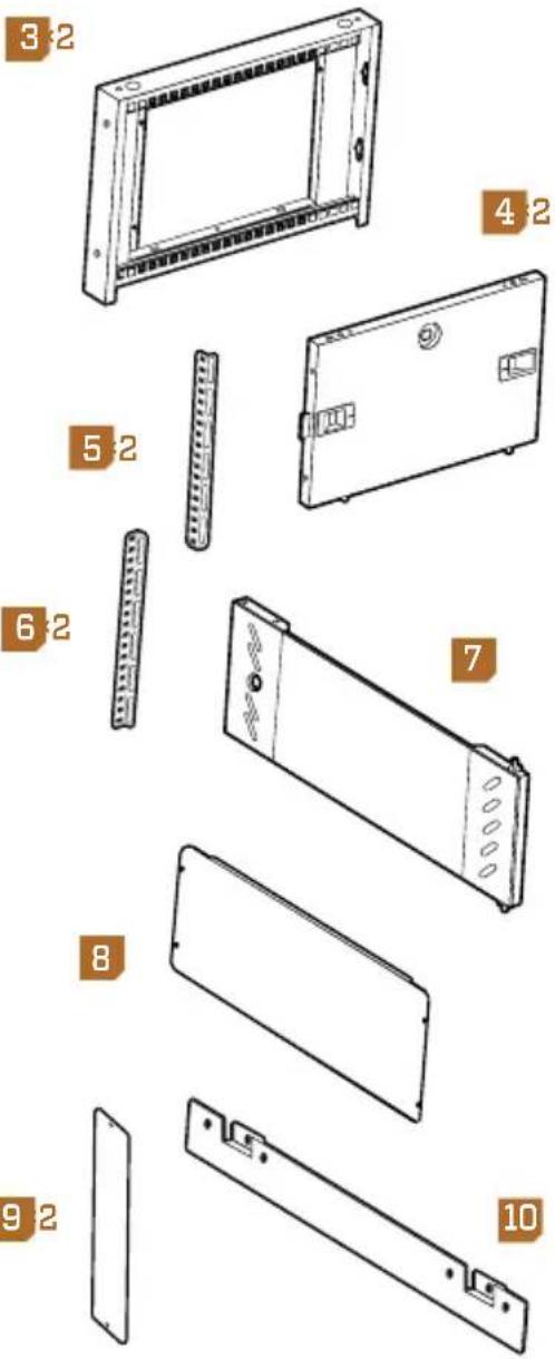
Assembly and Mounting Hardware
M6×11 screws (×16) ^A
Lock cylinder
M6×12 screws (×8) ^B
Plastic lock washer
M6 cage nuts
Metal hex washer
Rubber pads (×10)
Door latch
Small plugs (×8)
Door latch screw
M4×10 screws (×10) ^c
Keys (×2)
Door hinge plugs (×2)
Side door plugs (×2)
Small washers ( × 3)
For Rack Equipment
M6×14 screws (silver) (×10) M6 cage nuts (silver) (×10)
Tools Required for Assembly
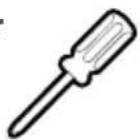
Phillips screwdriver
Screw Identifier
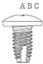
M6×11
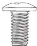
M6×12
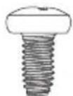
M4×10
Assembling the Rack
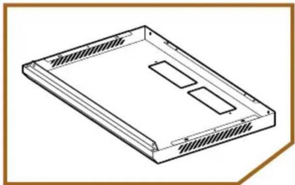
- Lay the bottom panel on a flat surface. The slotted edge is the front of the rack.
natural_image
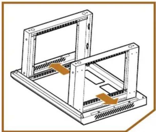
Isometric line drawing of a rectangular electronic device casing with internal compartments (no text or symbols)- Insert the side brackets onto the bottom panel so the mounting keyholes are at the back, and the depth adjustment rails are on the inside of the chassis.
natural_image
Technical line drawing of a mechanical frame assembly with no visible text or symbolsImportant! The depth adjustment rails should not be flush against the sides of the bottom panel. If they are, switch the left and right side brackets so the depth adjustment rails are about an inch inside the edges of the bottom panel.
If the side doors are preinstalled into the side brackets, press the two locking tabs inward and remove the doors to perform the next step.
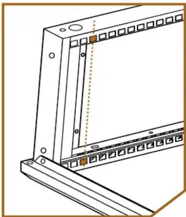
- Determine where the vertical rails will go inside the rack, and attach cage nuts to the top and bottom depth adjustment rails.
natural_image
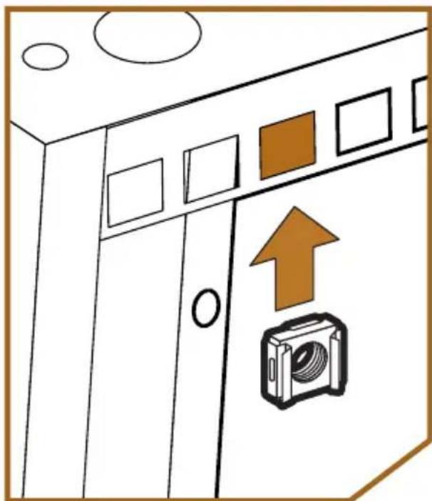
Technical line drawing of a mechanical assembly with mounting brackets and a vertical dotted line (no text or symbols)To install cage nuts, fit one of the clamps into the hole, apply pressure until the other clamp fits into the hole, and release.
Cage nuts can be installed by hand or with the help of a screwdriver or cage nut tool (available separately).
natural_image
Diagram of a kitchen appliance with a camera icon and directional arrow (no text or symbols)The front vertical rails will attach flush to the front of the rack. However, if you want to attach the door, you need to measure how far back you need to place your gear so the door can close.
To install a rack shelf or a large device that needs back-side support, measure the distance you need, and use the same method to attach the rear vertical rails at the appropriate depth.
Once you have determined where to attach the cage nuts, attaching the vertical rails in the next step might be easier by removing the side brackets and attaching the rails before proceeding with assembling the rack.
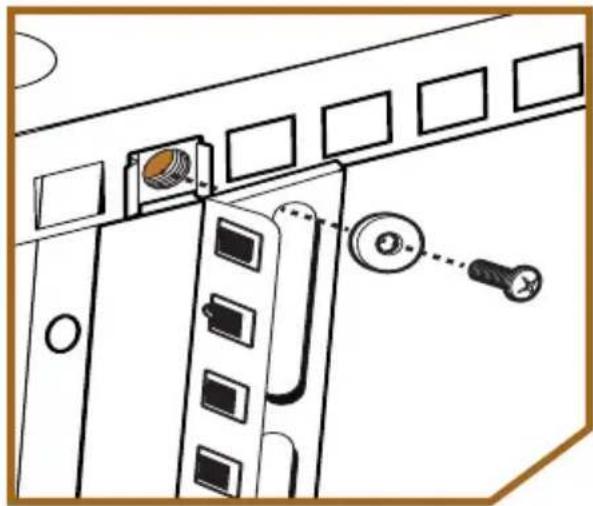
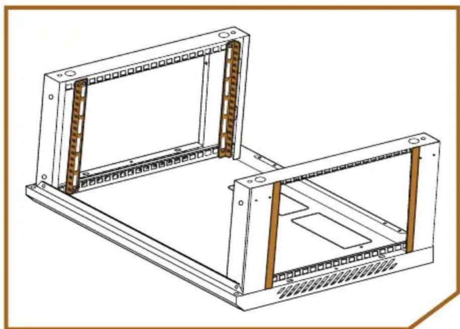
- Attach the vertical rails to the depth adjustment rails by screwing them into the cage nuts with M6×12 screws.
natural_image
Diagram of a door panel with labeled components and a close-up of a screw (no text or symbols present)Install the front vertical rails with the printed U-space guide and square holes facing front. Attach the rear rails with the printed U-space guide facing front or back, depending on your needs.
natural_image
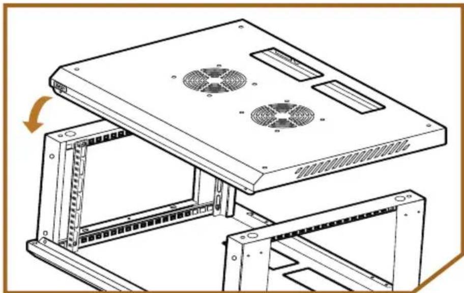
Technical line drawing of two rectangular electronic enclosure units with internal panel grilles (no text or symbols)- Fit the top panel over the assembly. Make sure the beveled vented edge is in the front.
natural_image
Technical line drawing of a server rack with two fans and mounting brackets (no text or symbols)- With the assembly in the upright position, use the M6 screws to attach the top panel to the side panels.
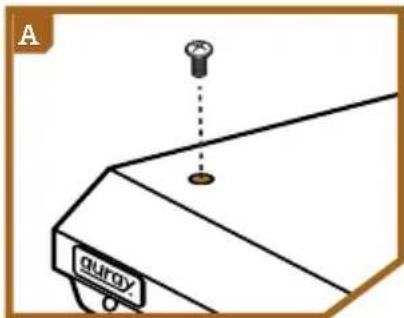
A Top screws (×4)
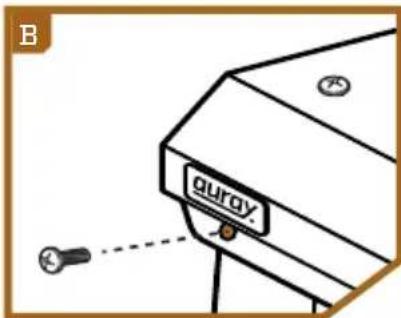
B Top front and back screws ( × 4)
natural_image
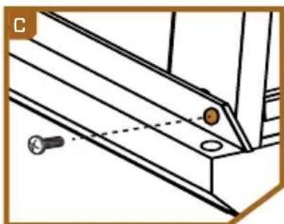
Technical line drawing of a structural joint with two screws and a bolt (no text or symbols)C Bottom front and back (×4)
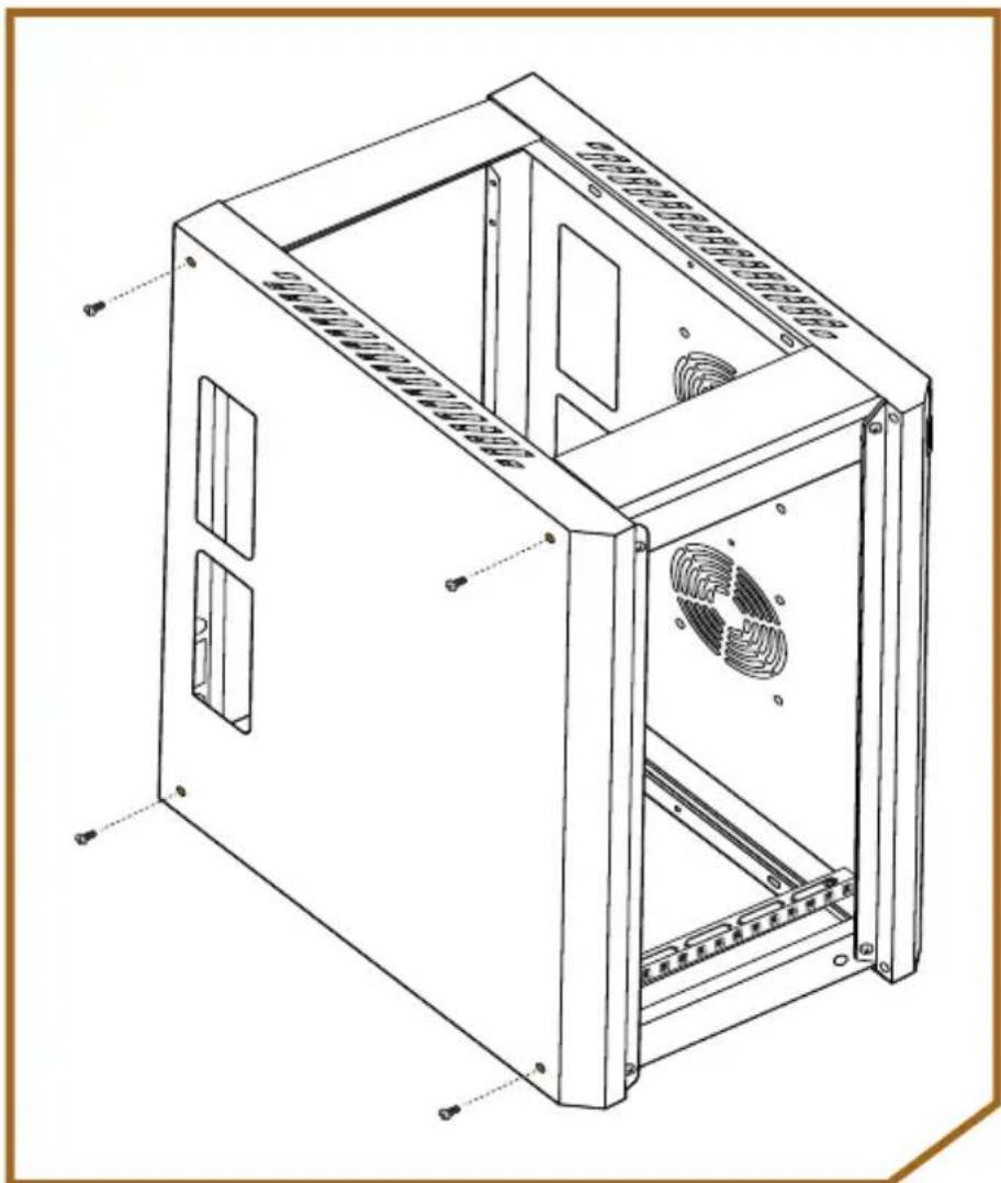
- Place the assembly on its side, and attach the side panels to the bottom panel with M6 screws. (×4)
Attaching the Fans
The Auray RKFN-1 (sold separately) is a dedicated fan for this server rack. It installs inside the top panel and can be used as exhaust or to blow air into the rack.
Air flows toward the fan's label.
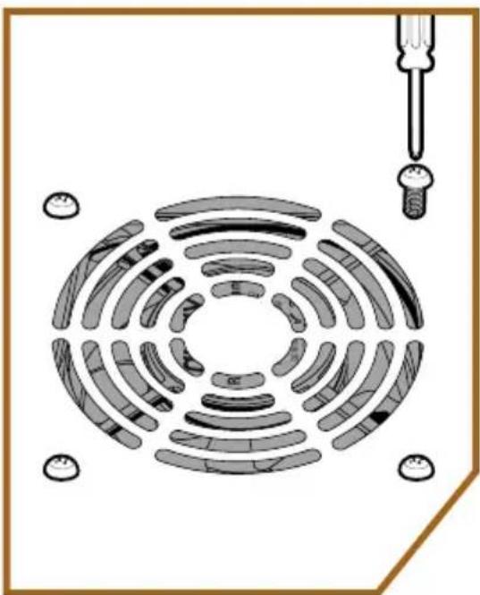
To attach the fan inside the rack, use the mounting screws that are included with the fan, and follow these steps:
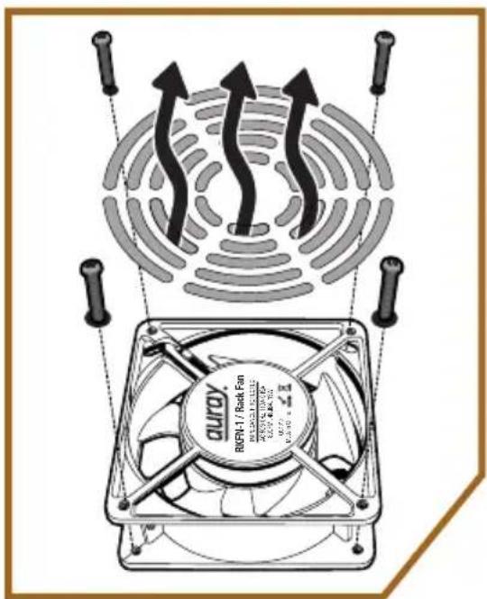
- Determine the air flow direction, and place the fan inside the top panel. Align the fans with the mounting holes inside the top panel.
natural_image
Diagram of a circular arrangement of segmented biological cells with a pipette inserted, no text or symbols present- Screw in the fans from the outside of the top panel until secure.
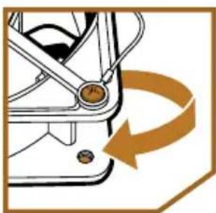
Important! A ground cable is attached to the front side of the fan and is set to be installed for exhaust. If you want the fan to blow air into the rack, unscrew the ground cable, and attach it to the other side of the fan. This will allow the fan to mount flush to the top panel.
natural_image
Mechanical component diagram showing a rotating arm with a curved arrow indicating rotational motion (no text or symbols)Installing Devices
When installing equipment, install the heaviest devices at the bottom of the rack first, and continue to install the lighter devices as you work your way up.
-
Determine the U-space of your device and where in the rack you want to install it. Use the U-space guides printed on the rails to determine where to install the silver M6 cage nuts.
-
Use the included silver M6×14 screws to secure the devices in place.
Completing the Rack Assembly
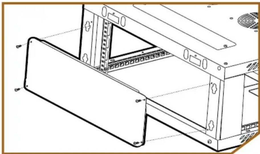
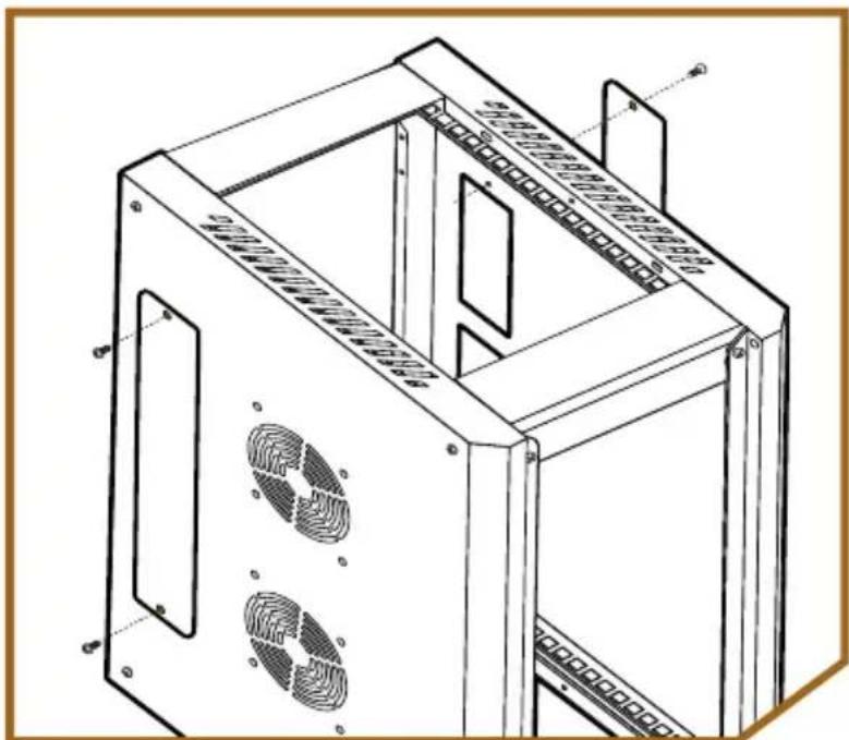
Determine if cables will run through the top and bottom cable ports or the back of the rack. If these openings are not going to be used, you can cover them to create a complete enclosure for your installed equipment.
- Attach the back panel with the M4×10 screws.
natural_image
Technical line drawing of a server rack unit with mounting brackets and internal components (no text or symbols)- Attach the top and bottom cable port covers with the M4×10 screws.
natural_image
Technical line drawing of a computer tower case with ventilation grilles and mounting brackets (no text or symbols)Side Panels
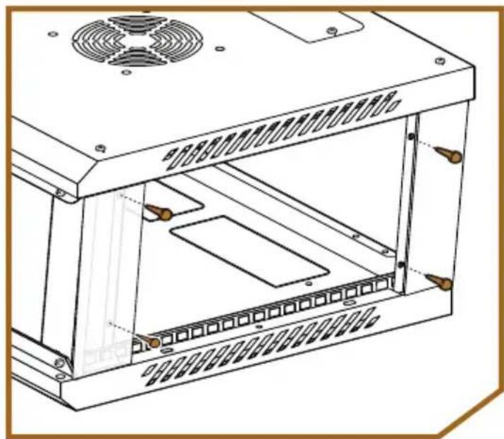
- Press the rubber pads into the holes on the side panels. (×4 per side)
natural_image
Technical line drawing of a server rack unit with ventilation slots and mounting holes (no text or symbols)-
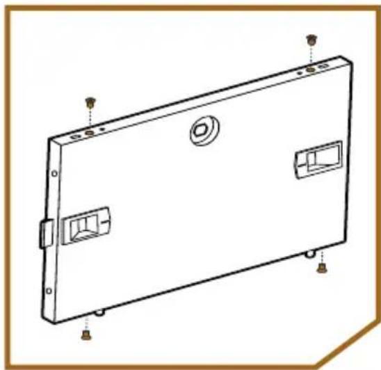
Place the small plugs in the top and bottom holes on the side panels. (×4 per side)
-
Attach the side panels by placing the bottom tabs into the slots, and pressing in the top until it locks into place.
natural_image
Line drawing of a rectangular electronic device with mounting holes and internal compartments (no text or symbols)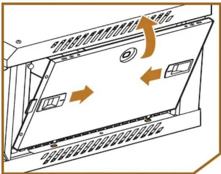
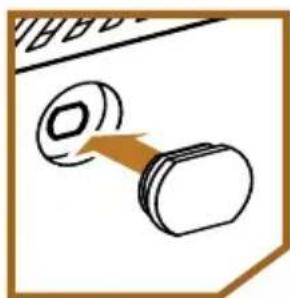
- If needed, press the door plugs into the side door holes.
natural_image
Simple line drawing of a dumbbell with a handle, no text or symbols presentAttaching the Mounting Bracket
-
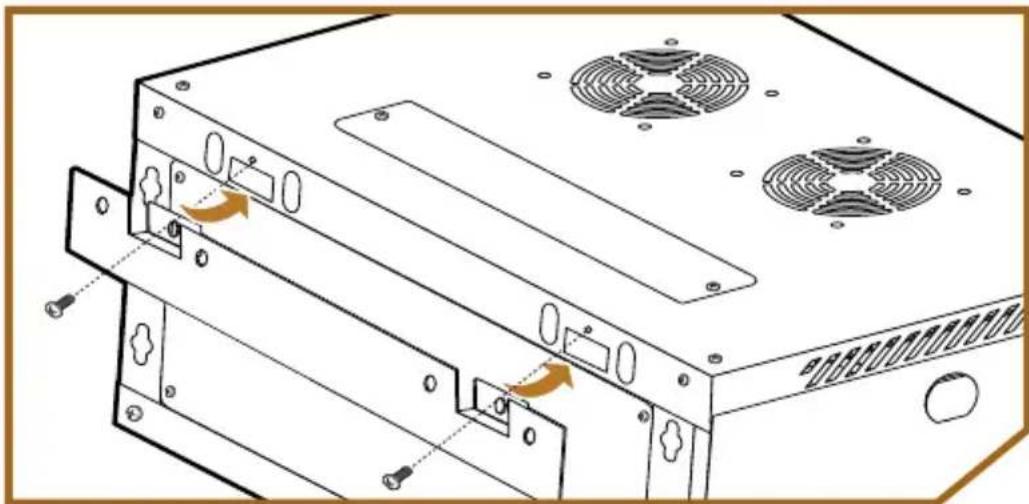
Slide the mounting bracket into the back of the rack so the indented tabs are inside the rack, the bracket should be flush against the back of the rack.
-
Attach the bracket with M4 screws (×2)
natural_image
Diagram of a computer tower with ventilation fans and drive slots, showing internal components without any text or symbols.Attaching the Door
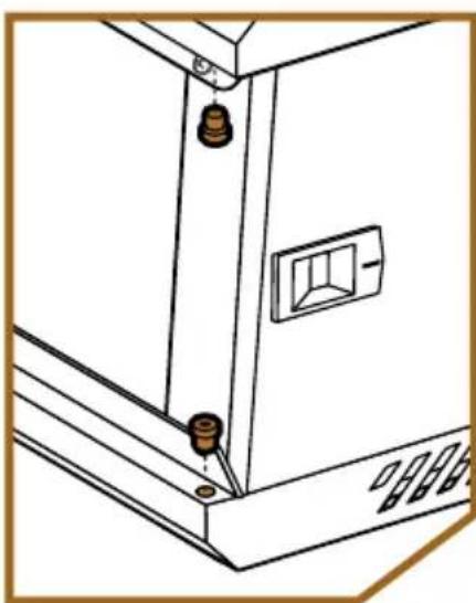
The door attaches to therack to open from the left.
- Place the door hinge plugs into the door holes on the right side of the top and bottom panels.
natural_image
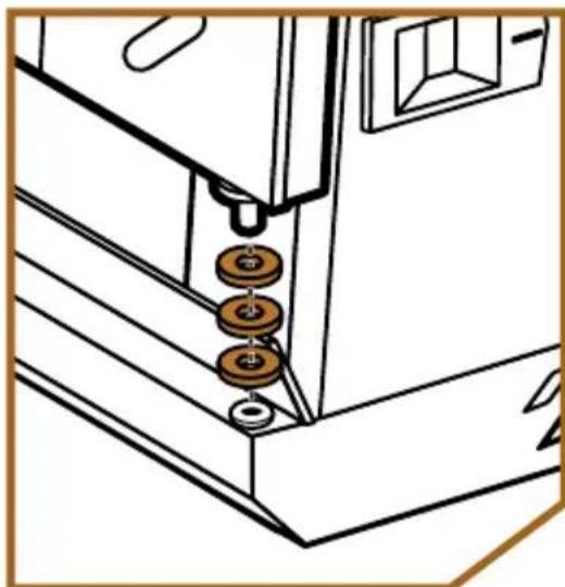
Line drawing of a cabinet or enclosure with mounting holes and a door (no text or symbols)- Place the three washers onto the bottom door pin.
natural_image
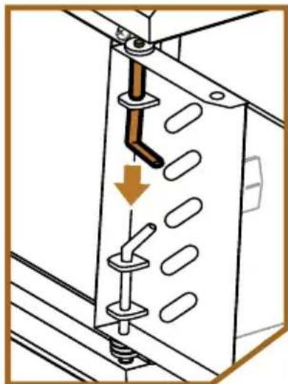
Technical line drawing of a door frame with three hanging weights and a window (no text or symbols)- Fit the bottom door pin into the hinge plug on the bottom panel. Pull down the top door pin, slide it into position under the top hinge plug, and release the door tab.
The door should smoothly swing open and closed.
natural_image
Diagram of a mechanical assembly with a lever and mounting bracket (no text or symbols)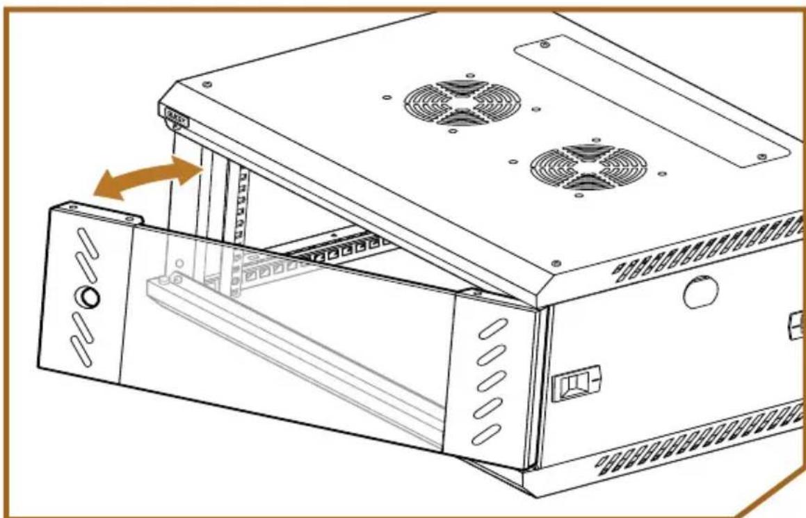
natural_image
Line drawing of a server rack unit with ventilation fans and an open panel (no text or symbols)Installing the Door Lock
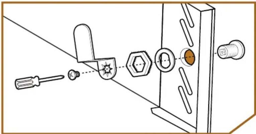
- Remove the metal hex washer and the plastic washer from the cylinder, and unscrew the Phillips screw from the end of the cylinder.
natural_image
Technical diagram showing a mechanical assembly with screwdriver, nut, bolt, and housing components (no text or labels)- Fit the cylinder through the hole.
- Slide the plastic washer over the cylinder threads. Then screw the metal washer onto the threads, making sure the textured side faces the plastic washer. Tighten until secure.
- Place the latch onto the end of the cylinder, and attach it with the screw.
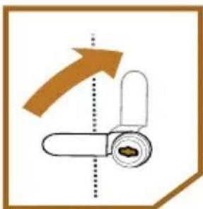
When you attach the latch, use the key to make sure it's oriented toward the edge of the rack so the door will lock.
natural_image
Diagram showing a mechanical component with an arrow indicating upward motion (no text or symbols)Specifications
Form Factor: 19 in. rack
Load Capacity: 132.3 lb. (60 kg)
Dimensions: SVRK-4U-S: 23.6 × 17.7 × 10.9 in. (60 × 45 × 27.7 cm)
SVRK-6U-S: 23.6 × 17.7 × 14.4 in. (60 × 45 × 36.7 cm)
SVRK-9U-S: 23.6 × 17.7 × 19.7 in. (60 × 45 × 50 cm)
SVRK-12U-S: 23.6 × 17.7 × 24.9 in. (60 × 45 × 63.3 cm)
SVRK-4U-D: 23.6 × 23.6 × 10.9 in. (60 × 60 × 27.7 cm)
SVRK-6U-D: 23.6 × 23.6 × 14.4 in. (60 × 60 × 36.7 cm)
SVRK-9U-D: 23.6 × 23.6 × 19.7 in. (60 × 60 × 50 cm)
SVRK-12U-D: 23.6 × 23.6 × 24.9 in. ( 60 × 60 × 63.3 cm)
Weight: SVRK-4U-S: 27.5 lb. (12.5 kg)
SVRK-6U-S: 32 lb. (14.5 kg)
SVRK-9U-S: 37.4 lb. (17 kg)
SVRK-12U-S: 41.9 lb. (19 kg)
SVRK-4U-D: 32 lb. (14.5 kg)
SVRK-6U-D: 37.4 lb. (17 kg)
SVRK-9U-D: 44.1 lb. (20 kg)
SVRK-12U-D: 51.8 lb. (23.5 kg)
One-Year Limited Warranty
This Auray product is warranted to the original purchaser to be free from defects in materials and workmanship under normal consumer use for a period of one (1) year from the original purchase date or thirty (30) days after replacement, whichever occurs later. The warranty provider's responsibility with respect to this limited warranty shall be limited solely to repair or replacement, at the provider's discretion, of any product that fails during normal use of this product in its intended manner and in its intended environment. Inoperability of the product or part(s) shall be determined by the warranty provider. If the product has been discontinued, the warranty provider reserves the right to replace it with a model of equivalent quality and function.
This warranty does not cover damage or defect caused by misuse, neglect, accident, alteration, abuse, improper installation or maintenance. EXCEPT AS PROVIDED HEREIN, THE WARRANTY PROVIDER MAKES NEITHER ANY EXPRESS WARRANTIES NOR ANY IMPLIED WARRANTIES, INCLUDING BUT NOT LIMITED TO ANY IMPLIED WARRANTY OF MERCHANTABILITY OR FITNESS FOR A PARTICULAR PURPOSE. This warranty provides you with specific legal rights, and you may also have additional rights that vary from state to state.
To obtain warranty coverage, contact the Auray Customer Service Department to obtain a return merchandise authorization (“RMA”) number, and return the defective product to Auray along with the RMA number and proof of purchase. Shipment of the defective product is at the purchaser’s own risk and expense.
For more information or to arrange service, visit www.aurayaudio.com or call Customer Service at 212-594-2353.
Product warranty provided by the Gradus Group.
www.gradusgroup.com
AURAY is a registered trademark of the Gradus Group. © 2023 Gradus Group LLC. All Rights Reserved.
- Thank you for choosing Auray.
- Precautions
- Overview
- Assembly and Mounting Hardware
- For Rack Equipment
- Tools Required for Assembly
- Screw Identifier
- Assembling the Rack
- Attaching the Fans
- Installing Devices
- Completing the Rack Assembly
- Side Panels
- Attaching the Mounting Bracket
- Attaching the Door
- Installing the Door Lock
- Specifications
- One-Year Limited Warranty
Brand : Auray
Model : SVRK-9U-S
Category : Uncategorized