
L3D-2TX4806-40GF - Switch AIRLIVE - Free user manual and instructions
Find the device manual for free L3D-2TX4806-40GF AIRLIVE in PDF.


| Product Type | Layer 3 Managed Gigabit Switch |
| Model | L3D-2TX4806-40GF |
| Brand | AirLive |
| Form Factor | 1U Rack-Mountable |
| Ports | 48 x 10/100/1000 Base-T RJ-45 |
| Uplinks | 2 x 10G Base-T Copper, 4 x 10G SFP+ Slots |
| Switching Capacity | 216 Gbps |
| MAC Address Table | 16K |
| VLAN Support | Up to 4094 VLANs, 802.1Q |
| Management | Web GUI, CLI, SNMP v1/v2c/v3, SSH, Telnet |
| Power Supply | AC 100-240V, 50/60Hz, Built-in |
| Power Consumption | 60W (Maximum) |
| Dimensions (W x D x H) | 440 x 300 x 44 mm (17.3 x 11.8 x 1.7 in) |
| Weight | 5.5 kg (12.1 lbs) |
| Operating Temperature | 0°C to 50°C (32°F to 122°F) |
| Operating Humidity | 10% to 90% Non-condensing |
| Safety Certification | FCC Class A, CE |
| LED Indicators | Per Port: Link/Act, Speed; System: Power, Status |
| Cooling | 2 x Fan, Front-to-Back Airflow |
| Mounting | Rack Mount Brackets Included |
| Warranty | 3 Years Limited |
Frequently Asked Questions - L3D-2TX4806-40GF AIRLIVE
User questions about L3D-2TX4806-40GF AIRLIVE
0 question about this device. Answer the ones you know or ask your own.
Ask a new question about this device
Download the instructions for your Switch in PDF format for free! Find your manual L3D-2TX4806-40GF - AIRLIVE and take your electronic device back in hand. On this page are published all the documents necessary for the use of your device. L3D-2TX4806-40GF by AIRLIVE.
USER MANUAL L3D-2TX4806-40GF AIRLIVE
natural_image
Abstract blue line drawing resembling a stylized letter 'a' with a dot above, no text or symbols present.airlive®
Table of Contents
1 Preface....25
1.1 Declaration....25
1.2 Suggestion feedback....25
1.3 Audience....25
2 Basic Configuration Guide....26
2.1 Configuring System Management ....26
2.1.1 Overview 26
2.1.2 Configuration.... 27
2.1.3 Application cases 29
2.2 Configuring User Management....29
2.2.1 Overview 29
2.2.2 Configuration 30
2.2.3 Application cases 32
2.3 Configuring FTP 32
2.3.1 Overview 32
2.3.2 Configuration.... 33
2.3.3 Application cases 34
2.4 Configuring FTP SERVER....34
2.4.1 Overview 34
2.4.2 Configuration 35
2.4.3 Application cases 36
2.5 Configuring TFTP 37
2.5.1 Overview 37
2.5.2 Configuration 37
2.5.3 Application cases 38
2.6 Configuring SCP ....38
2.6.1 Overview 38
2.6.2 Configuration.... 39
2.6.3 Application cases 40
2.7 Configuring Telnet....40
2.7.1 Overview 40
2.7.2 Configuration 40
2.7.3 Application cases 41
2.8 Configuring SSH 42
2.8.1 Overview 42
Table of Contents
| 2.8.2 Configuration | 42 |
| 2.8.3 Application cases | 44 |
2.9 Configuring Time&timezone....44
2.9.1 Overview 44
2.9.2 Configuration....44
2.9.3 Application cases 45
2.10 Configuring License ....45
2.10.1 Overview 45
2.10.2 Configuration....46
2.11 RPC API Configuration Guide....47
2.11.1 Overview 47
2.11.2 Configuration 50
2.11.3 Application cases 52
2.12 Configuring HTTP 52
2.12.1 Overview 52
2.12.2 Configuration 52
2.12.3 Application cases 53
3 Ethernet Configuration Guide ....54
3.1 Configuring Interface ....54
3.1.1 Overview 54
3.1.2 Configuration....55
3.1.3 Application cases .... 57
3.2 Configuring Layer3 Interfaces....57
3.2.1 Overview 57
3.2.2 Configuration....58
3.3 Configuring Interface Errdisable 60
3.3.1 Overview 60
3.3.2 Configuration....61
3.3.3 Application cases 64
3.4 Configuring MAC Address Table 64
3.4.1 Overview 64
3.4.2 Configuration....65
3.4.3 Application cases 69
3.5 Configuring VLAN 69
3.5.1 Overview 69
3.5.2 Configuration 71
3.5.3 Application cases 74
3.6 Configuring Voice VLAN....74
3.6.1 Overview 74
3.6.2 Configuration....75
Table of Contents
3.6.3 Application cases 76
3.7 Configuring VLAN Classification....76
3.7.1 Overview 76
3.7.2 Configuration....77
3.7.3 Application cases 79
3.8 Configuring VLAN Mapping ....79
3.8.1 Overview 79
3.8.2 Configuration 81
3.8.3 Application cases 87
3.9 Configuring Link Aggregation ....87
3.9.1 Overview 87
3.9.2 Configuration 88
3.9.3 Application cases 93
3.10 Configuring Flow Control....94
3.10.1 Overview 94
3.10.2 Configuration 94
3.10.3 Application cases ...... 96
3.11 Configuring Storm Control....96
3.11.1 Overview ...... 96
3.11.2 Configuration....97
3.11.3 Application cases 98
3.12 Configuring Loopback Detection 99
3.12.1 Overview 99
3.12.2 Configuration....99
3.12.3 Application cases 102
3.13 Configuring Layer 2 Protocols Tunneling 103
3.13.1 Overview 103
3.13.2 Configuration.... 103
3.13.3 Application cases 106
3.14 Configuring MSTP 106
3.14.1 Overview 106
3.14.2 Configuration.... 107
3.14.3 Application cases 112
3.15 Configuring MLAG 112
3.15.1 Overview 112
3.15.2 Configuration.... 113
3.15.3 Application cases 116
3.16 Configuring Hash Load-balance 116
3.16.1 Configuring Linkagg Hash.... 116
3.16.2 Configuring ECMP Hash.... 127
3.16.3 Configuring ECMP Hash.... 134
Table of Contents
3.17 Configuring PORT-XCONNECT 135
3.17.1 Overview 135
3.17.2 Configuration.... 135
3.17.3 Application cases 136
4 IP Service Configuration Guide .... 137
4.1 Configuring Arp.... 137
4.1.1 Overview 137
4.1.2 Configuration.... 138
4.1.3 Application cases 140
4.2 Configuring Arp proxy.... 140
4.2.1 Overview 140
4.2.2 Configuration 141
4.2.3 Application cases 147
4.3 Configuring DHCP Client 147
4.3.1 Overview 147
4.3.2 Configuration....148
4.3.3 Application cases 149
4.4 Configuring DHCP Relay 150
4.4.1 Overview 150
4.4.2 Configuration....150
4.4.3 Application cases 152
4.5 Configuring DHCP server.... 153
4.5.1 Overview 153
4.5.2 Configuration....154
4.5.3 Application cases .... 159
4.6 Configuring DNS.... 159
4.6.1 Overview 159
4.6.2 Configuration....159
4.6.3 Application cases 160
5 IP Routing Configuration Guide.... 161
5.1 Configuring IP Unicast-Routing 161
5.1.1 Overview 161
5.1.2 Configuration 162
5.1.3 Application cases .... 165
5.2 Configuring RIP 165
5.2.1 Overview 165
5.2.2 Configuration 166
5.2.3 Application cases 191
5.3 Configuring OSPF 191
5.3.1 Overview 191
Table of Contents
| 5.3.2 Configuration | 192 |
| 5.3.3 Application cases | 217 |
| 5.3.4 Application cases | 220 |
5.4 Configuring Prefix-list 220
5.4.1 Overview 220
5.4.2 Configuration 221
5.4.3 Application cases 224
5.5 Configuring Route-map 224
5.5.1 Overview 224
5.5.2 Configuration 225
5.5.3 Application cases 227
5.6 Configuring Policy-Based Routing.... 227
5.6.1 Overview 227
5.6.2 Configuration 228
5.6.3 Application cases 232
5.7 Configuring BGP 232
5.7.1 Overview 232
5.7.2 Configuration....233
5.7.3 Application cases 238
5.8 Configuring ISIS.... 238
5.8.1 Overview 238
5.8.2 Configuration 240
5.8.3 Application cases 244
6 Multicast Configuration Guide 245
6.1 Configuring IP Multicast-Routing 245
6.1.1 Overview 245
6.1.2 Configuration....246
6.1.3 Application cases 246
6.2 Configuring IGMP 246
6.2.1 Overview 246
6.2.2 Configuration....247
6.2.3 Application cases 250
6.3 Configuring PIM-SM 250
6.3.1 Overview 250
6.3.2 Configuration 254
6.3.3 Application cases 263
6.4 Configuring PIM-DM 263
6.4.1 Overview 263
6.4.2 Configuration 264
6.4.3 Application cases 266
Table of Contents
6.5 Configuring IGMP Snooping....267
6.5.1 Overview 267
6.5.2 Configuration....268
6.5.3 Application cases 275
6.6 Configuring MVR 275
6.6.1 Overview 275
6.6.2 Configuration....276
6.6.3 Application cases 279
7 Security Configuration Guide ...... 280
7.1 Configuring Port Security.... 280
7.1.1 Overview 280
7.1.2 Configuration 281
7.1.3 Application cases 282
7.2 Configuring Vlan Security 283
7.2.1 Overview 283
7.2.2 Configuration....284
7.2.3 Application cases 285
7.3 Configuring Time-Range 285
7.3.1 Overview 285
7.3.2 Configuration 285
7.3.3 Application cases ...... 286
7.4 Configuring ACL 287
7.4.1 Overview 287
7.4.2 Configuration....288
7.4.3 Application cases 290
7.5 Configuring Extern ACL 290
7.5.1 Overview 290
7.5.2 Configuration....291
7.5.3 Application cases 292
7.6 Configuring IPv6 ACL.... 293
7.6.1 Overview 293
7.6.2 Configuration....294
7.6.3 Application cases 296
7.7 Configuring Port-Group 296
7.7.1 Overview 296
7.7.2 Configuration....296
7.7.3 Application cases 297
7.8 Configuring Vlan-Group 297
7.8.1 Overview 297
7.8.2 Configuration....297
Table of Contents
7.8.3 Application cases 298
7.9 Configuring COPP ACL 298
7.9.1 Overview 298
7.9.2 Configuration 299
7.9.3 Application cases 301
7.10 Configuring dot1x.... 301
7.10.1 Overview 301
7.10.2 Configuration 302
7.10.3 Application cases 306
7.11 Configuring Guest VLAN 308
7.11.1 Overview 308
7.11.2 Configuration 309
7.11.3 Application cases 315
7.12 Configuring ARP Inspection.... 315
7.12.1 Overview 315
7.12.2 Configuration 316
7.12.3 Application cases 318
7.13 Configuring DHCP Snooping 318
7.13.1 Overview 318
7.13.2 Configuration 319
7.13.3 Application cases 321
7.14 Configuring IP source guard 321
7.14.1 Overview 321
7.14.2 Configuration 323
7.14.3 Application cases 324
7.15 Configuring Private-vlan 325
7.15.1 Overview 325
7.15.2 Configuration 325
7.15.3 Application cases 327
7.16 Configuring AAA 327
7.16.1 Overview 327
7.16.2 Configuration 328
7.16.3 Application cases 330
7.17 Configuring TACACS+ 332
7.17.1 Overview 332
7.17.2 Configuration 333
7.17.3 Application cases 335
7.18 Configuring Port Isolate 336
7.18.1 Overview 336
7.18.2 Configuration.... 336
7.18.3 Application cases 337
Table of Contents
7.19 Configuring DDoS.... 338
7.19.1 Overview 338
7.19.2 Configuration....339
7.19.3 Application cases 340
7.20 Configuring Key Chain 341
7.20.1 Overview 341
7.20.2 Configuration 341
7.20.3 Application cases 342
7.21 Configuring Port-Block 342
7.21.1 Overview 342
7.21.2 Configuration 343
7.21.3 Application cases 343
8 Device Management Configuration Guide 344
8.1 Configuring STM.... 344
8.1.1 Overview 344
8.1.2 Configuration 345
8.1.3 Application cases 346
8.2 Configuring syslog 346
8.2.1 Overview 346
8.2.2 Configuration....349
8.2.3 Application cases 351
8.3 Configuring mirror 351
8.3.1 Overview 351
8.3.2 Configuration 356
8.3.3 Application cases 366
8.4 Configuring Device Management 367
8.4.1 Overview 367
8.4.2 Configuration 367
8.4.3 Application cases ...... 373
8.5 Configuring Bootrom 374
8.5.1 Overview 374
8.5.2 Configuration....374
8.5.3 Application cases 377
8.6 Configuring SmartConfig 378
8.6.1 Overview 378
8.6.2 Configuration.... 379
8.6.3 Application cases 381
8.7 Reboot Logs.... 381
8.7.1 Overview 381
8.7.2 Configuration 382
Table of Contents
| 8.7.3 Application cases | 382 |
9 Network Management Configuration Guide 383
9.1 Configuring Network Diagnosis 383
9.1.1 Overview 383
9.1.2 Configuration 384
9.1.3 Application cases 384
9.2 Configuring NTP 385
9.2.1 Overview 385
9.2.2 Configuration 385
9.2.3 Application cases 388
9.3 Configuring Phy Loopback 390
9.3.1 Overview 390
9.3.2 Configuration 390
9.3.3 Application cases 392
9.4 Configuring L2 ping.... 393
9.4.1 Overview 393
9.4.2 Configuration....393
9.4.3 Application cases 394
9.5 Configuring RMON 395
9.5.1 Overview 395
9.5.2 Configuration.... 395
9.5.3 Application cases 397
9.6 Configuring SNMP 397
9.6.1 Overview 397
9.6.2 Configuration....398
9.6.3 Application cases 402
9.7 Configuring SFLOW 403
9.7.1 Overview 403
9.7.2 Configuration 404
9.7.3 Application cases 406
9.8 Configuring LLDP 406
9.8.1 Overview 406
9.8.2 Configuration 406
9.9 Configuring IPFIX....409
9.9.1 Overview 409
9.9.2 Configuration 409
9.9.3 Application cases 411
10 Traffic Management Configuration Guide 412
10.1 Configuring QoS....412
10.1.1 Overview 412
Table of Contents
10.1.2 Configuration 420
10.1.3 Configuration for Queue 426
10.1.4 Configuration for Port shaping & port policing 431
10.1.5 Application cases 432
11 IPv6 Service Configuration.... 433
11.1 Configuring IPv6 over IPv4 Tunnel 433
11.1.1 Overview 433
11.1.2 Configuration 437
11.1.3 Application cases 451
11.2 Configuring ND.... 451
11.2.1 Overview 451
11.2.2 Configuration 452
11.2.3 Application cases 453
11.3 Configuring DHCPv6 Relay 453
11.3.1 Overview 453
11.3.2 Configuration 454
11.3.3 Application cases 456
12 IPv6 Security Configuration Guide 457
12.1 DHCPv6 Snooping Configuration 457
12.1.1 Overview 457
12.1.2 Configuration 457
12.1.3 Application cases 459
13 IPv6 Routing Configuration 460
13.1 Configuring IPv6 Unicast-Routing 460
13.1.1 Overview 460
13.1.2 Configuration 461
13.1.3 Application cases 463
13.2 Configuring OSPFv3.... 463
13.2.1 Overview 463
13.2.2 Configuration 464
13.2.3 Application cases 492
13.3 Configuring RIPng 492
13.3.1 Overview 492
13.3.2 Configuration 493
13.3.3 Application cases 509
13.4 Configuring lpv6 Prefix-list.... 509
13.4.1 Overview 509
13.4.2 Configuration....510
13.4.3 Application cases 512
14 IPv6 Multicast Configuration Guide....513
Table of Contents
14.1 Configuring IPv6 Multicast-Routing 513
14.1.1 Overview 513
14.1.2 Configuration....514
14.1.3 Application cases 514
14.2 Configuring MLD 514
14.2.1 Overview 514
14.2.2 Configuration....516
14.2.3 Application cases 518
14.3 Configuring PIMv6-SM 518
14.3.1 Overview 518
14.3.2 Configuration 522
14.3.3 Application cases 532
14.4 Configuring PIMv6-DM.... 532
14.4.1 Overview 532
14.4.2 Configuration....533
14.4.3 Application cases 535
14.5 Configuring MLD Snooping 536
14.5.1 Overview 536
14.5.2 Configuration.... 537
14.5.3 Application cases 544
14.6 Configuring MVR6 544
14.6.1 Overview 544
14.6.2 Configuration....545
14.6.3 Application cases 548
15 VPN Configuration Guide.... 549
15.1 Configuring VPN.... 549
15.1.1 Overview 549
15.1.2 Configuration 549
15.1.3 Application cases 550
15.2 Configuring IPv4 GRE Tunnel.... 551
15.2.1 Overview 551
15.2.2 Configuration 552
15.2.3 Application cases 555
16 Reliability Configuration Guide.... 556
16.1 Configuring BHM 556
16.1.1 Overview 556
16.1.2 Configuration....556
16.1.3 Application cases 557
16.2 Configuring EFM OAM....557
16.2.1 Overview 557
Table of Contents
| 16.2.2 Configuration | 558 |
| 16.2.3 Application cases | 564 |
16.3 Configuring CFM 564
16.3.1 Overview 564
16.3.2 Configuration 566
16.3.3 Application cases 585
16.4 Configuring CPU Traffic 585
16.4.1 Overview 585
16.4.2 Configuration....590
16.4.3 Application cases 592
16.5 Configuring G.8031 592
16.5.1 Overview 592
16.5.2 Configuration....593
16.5.3 Application cases 596
16.6 Configuring G8032....596
16.6.1 Overview 596
16.6.2 Topology....597
16.6.3 Configuration of single ring....598
16.6.4 Configuration of multiple rings - Non-virtual-channel 602
16.6.5 Configuration of multiple rings - Virtual-channel....607
16.6.6 Linkage between G8032 and CFM.... 612
16.7 Configuring UDLD 619
16.7.1 Overview 619
16.7.2 Configuration 619
16.7.3 Application cases 621
16.8 Configuring ERPS 621
16.8.1 Overview 621
16.8.2 Configuration....621
16.8.3 Application cases 632
16.9 Configuring Smart Link.... 632
16.9.1 Overview 632
16.9.2 Configuration 633
16.9.3 Application cases 637
16.10 Configuring Multi-Link 638
16.10.1 Overview 638
16.10.2 Configuration 638
16.10.3 Application cases 641
16.11 Configuring Monitor Link.... 647
16.11.1 Overview 647
16.11.2 Configuration....648
16.11.3 Application cases 649
Table of Contents
16.12 Configuring VRRP 649
16.12.1 Overview 649
16.12.2 Configuration....652
16.12.3 Application cases 661
16.13 Configuring Track.... 662
16.13.1 Overview 662
16.13.2 Configuration....663
16.13.3 Application cases 681
16.14 Configuring IP BFD 681
16.14.1 Overview 681
16.14.2 Configuration 682
16.14.3 Application cases 687
16.15 Configuring VARP 687
16.15.1 Overview 687
16.15.2 Configuration 688
16.15.3 Application cases 689
16.16 Configuring UDP Helper 690
16.16.1 Overview 690
16.16.2 Configuration....691
16.16.3 Application cases 692
17 DataCenter Configuration Guide....693
17.1 Configuring VXLAN 693
17.1.1 Overview 693
17.1.2 Configuration....693
17.2 Configuring NVGRE.... 714
17.2.1 Overview 714
17.2.2 Configuration 714
17.2.3 Application cases 721
17.3 Configuring GENEVE.... 721
17.3.1 Overview 721
17.3.2 Configuration 721
17.3.3 Application cases 728
17.4 Configuring Overlay 728
17.4.1 Overview 728
17.4.2 Configuration 728
17.4.3 Application cases 736
17.5 Configuring Prioprity-based Flow Control 736
17.5.1 Overview 736
17.5.2 Configuration....737
17.5.3 Application cases....739
Table of Contents
17.6 Configuring OVSDB.... 740
17.6.1 Overview 740
17.6.2 Configuration....743
17.6.3 Application cases 745
17.7 Configuring EFD 745
17.7.1 Overview 745
17.7.2 Configuration....746
17.7.3 Application cases....748
18 MPLS Configuration Guide....749
18.1 Configuring LDP 749
18.1.1 Overview 749
18.1.2 Configuration....750
18.2 Configuring MPLS....752
18.2.1 Overview 752
18.2.2 Configuration....753
18.2.3 Application cases....755
18.3 Configuring VPLS 755
18.3.1 Overview 755
18.3.2 Configuration....756
18.3.3 Application cases....771
18.4 Configuring VPWS 771
18.4.1 Overview 771
18.4.2 Configuration 772
18.4.3 Application cases 778
18.5 Configuring MPLS QoS....778
18.5.1 Overview 778
18.5.2 MPLS LSP Model 779
18.5.3 Configuration....780
18.5.4 Application cases 789
18.6 Configuring L3VPN....789
18.6.1 Overview 789
18.6.2 Configuration 789
18.6.3 Application cases 794
19 PoE....795
19.1 PoE Overview 795
19.2 features and configurations 795
19.2.1 Configuring Global PoE power management scheme 795
19.2.2 Configuring power-reserved 802
19.2.3 Configure threshold-power-percentage 803
19.2.4 Enable port PoE feature....803
Table of Contents
19.2.5 Configuring the Power Supply Priority....803
19.2.6 Trigger an autoclass measurement....804
19.3 Example for Configuring PoE.... 804
List of Figures
Figure 2-1 SSH system application....42
Figure 3-1 Interface Name .... 54
Figure 3-2 Mac address aging....65
Figure 3-3 Static mac address table....66
Figure 3-4 Static multicast mac address table 67
Figure 3-5 mac address filter....68
Figure 3-6 Tagged Frame 70
Figure 3-7 Trunk link....70
Figure 3-8 Access link....70
Figure 3-9 Access link....71
Figure 3-10 Trunk link....72
Figure 3-11 vlan classification....77
Figure 3-12 QinQ Tunnel....80
Figure 3-13 vlan mapping....81
Figure 3-14 QinQ Tunnel....83
Figure 3-15 QinQ Tunnel....83
Figure 3-16 QinQ Tunnel....85
Figure 3-17 Dynamic LACP....88
Figure 3-18 Static LACP 90
Figure 3-19 Static Agg....92
Figure 3-20 Flow control....94
Figure 3-21 Percentage Storm Control....97
Figure 3-22 PPS Storm Control....98
Figure 3-23 L2 protocol tunnel....103
Figure 3-24 MSTP....107
Figure 3-25 MLAG....113
Figure 4-1 arp....138
Figure 4-2 arp proxy....141
Figure 4-3 local arp proxy .... 144
Figure 4-4 dhcp client....148
Figure 4-5 DHCP relay 150
Figure 4-6 DHCP server 154
Figure 4-7 DHCP relay 156
Figure 4-8 DNS 159
Figure 5-1 ip unicast routing.... 162
Figure 5-2 enable rip....166
Figure 5-3 rip version....168
Figure 5-4 rip metric 171
Figure 5-5 rip distance....174
Figure 5-6 rip redistribute....176
Figure 5-7 rip split-horizon....179
Figure 5-8 rip filter list....183
Figure 5-9 rip authentication.... 185
Figure 5-10 rip authentication.... 188
Figure 5-11 ospf 193
Figure 5-12 ospf priority.... 196
Figure 5-13 ospf area 199
Figure 5-14 ospf redistribute 203
Figure 5-15 ospf cost....209
Figure 5-16 ospf authentication 213
Figure 5-17 pbr....228
Figure 5-18 pbr....229
Figure 5-19 EBGP....233
Figure 5-20 IBGP....236
Figure 5-21 RIPng....240
Figure 6-1 Pim sm 254
Figure 6-2 bsr....260
Figure 6-3 Pim dm....264
Figure 6-4 mvr....276
Figure 7-1 Port Security....281
Figure 7-2 acl.... 288
Figure 7-3 extern acl....291
Figure 7-4 ipv6 acl....294
Figure 7-5 copp_acl....299
Figure 7-6 dot1x....302
Figure 7-7 Select "Setting-> System" 306
Figure 7-8 Configure the shared-key, authorization port and account port.... 307
Figure 7-9 Add user name and password on the server.... 307
Figure 7-10 Guest vlan: before authenticated.... 309
Figure 7-11 Guest vlan: after authenticated .... 310
Figure 7-12 arp inspection.... 316
Figure 7-13 dhcp snooping.... 319
Figure 7-14 ip source guard.... 323
Figure 7-15 private vlan.... 325
Figure 7-16 private vlan.... 328
Figure 7-17 Telnet connecting test.... 329
Figure 7-18 Set IP address for PC.... 330
Figure 7-19 Connectivity test 331
Figure 7-20 WinRadius.... 331
Figure 7-21 WinRadius.... 331
Figure 7-22 Add user and password 332
Figure 7-23 Connectivity test .... 332
Figure 7-24 TACACS+ 333
Figure 7-25 Telnet connecting test.... 335
Figure 7-26 Connectivity test .... 335
Figure 7-27 Port Isolate.... 336
Figure 7-28 Topology for DDoS test.... 339
Figure 8-1 syslog server....349
Figure 8-2 syslog on server.... 351
Figure 8-3 Mirror 352
Figure 8-4 port Mirror.... 356
Figure 8-5 Multi-destination Mirror.... 359
Figure 8-6 Remote Mirror ...... 361
Figure 8-7 Mirror to cpu.... 364
Figure 8-8 smart config.... 379
Figure 9-1 NTP 386
Figure 9-2 external phy topology....390
Figure 9-3 Internal phy topology.... 391
Figure 9-4 Port level topology .... 392
Figure 9-5 ping a switch port.... 393
Figure 9-6 rmon....395
Figure 9-7 snmp....398
Figure 9-8 sflow....404
Figure 9-9 lldp 406
Figure 11-1 IPv6 over IPv4 Tunnel.... 433
Figure 11-2 IPv6 over IPv4 Tunnel.... 436
Figure 11-3 ISATAP Tunnel 437
Figure 11-4 Manual Tunnel.... 437
Figure 11-5 6to4 tunnel 441
Figure 11-6 6to4 relay.... 444
Figure 11-7 ISATAP tunnel....448
Figure 11-8 NDP....452
Figure 11-9 DHCP Relay....454
Figure 12-1 DHCPv6 Snooping....457
Figure 13-1 ipv6 unicast routing.... 461
Figure 13-2 OSPFv3....465
Figure 13-3 OSPFv3 priority 467
Figure 13-4 OSPFv3 area.... 471
Figure 13-5 OSPFv3 Redistribute....477
Figure 13-6 OSPFv3 Cost....483
Figure 13-7 RIPng....493
Figure 13-8 RIPng Metric.... 497
Figure 13-9 RIPng Distance....499
Figure 13-10 RIPng redistribute....501
Figure 13-11 RIPng Split-horizon 504
Figure 13-12 RIPng Route Distribute Filters 507
Figure 14-1 PIMv6 Sparse-mode....522
Figure 14-2 BSR 529
Figure 14-3 PIMv6 dense-mode....533
Figure 14-4 MVR6 545
Figure 15-1 IPv4 gre over IPv4....551
Figure 15-2 IPv4 gre Tunnel 553
Figure 16-1 EFM....558
Figure 16-2 EFM....560
Figure 16-3 EFM....562
Figure 16-4 EFM....564
Figure 16-5 CFM.... 567
Figure 16-6 CFM....576
Figure 16-7 CFM CSF 577
Figure 16-8 CFM....580
Figure 16-9 CFM....582
Figure 16-10 CFM....584
Figure 16-11 G.8031 593
Figure 16-12 Topology of single G8032 ring....597
Figure 16-13 Topology of multiple G8032 rings 598
Figure 16-14 UDLD 619
Figure 16-15 ERPS 622
Figure 16-16 ERPS 626
Figure 16-17 Smart-Link Typical Topology....633
Figure 16-18 Multi-Link Typical Topology 638
Figure 16-19 Multilink-enhance Typical Topology 643
Figure 16-20 monitor link....648
Figure 16-21 Without VRRP 651
Figure 16-22 With VRRP 652
Figure 16-23 VRRP with one virtual router.... 652
Figure 16-24 VRRP with two virtual router 655
Figure 16-25 VRRP Circuit Failover 658
Figure 16-26 IP SLA....663
Figure 16-27 IP SLA....666
Figure 16-28 IP SLA....668
Figure 16-29 Track interface....670
Figure 16-30 Track ip sla....672
Figure 16-31 Track ip sla....673
Figure 16-32 Track bfd 675
Figure 16-33 VRRP Track.... 677
Figure 16-34 Static Route Track....678
Figure 16-35 BFD single hop....682
Figure 16-36 BFD multi hop....685
Figure 16-37 VARP with MALG....688
Figure 16-38 UDP-Helper configuration 690
Figure 17-1 Vxlan....693
Figure 17-2 Vxlan....697
Figure 17-3 EBGP_EVPN 700
Figure 17-4 IBGP_EVPN 706
Figure 17-5 NVGRE....714
Figure 17-6 NVGRE....717
Figure 17-7 GENEVE....721
Figure 17-8 GENEVE....724
Figure 17-9 Overlay multiple source ip....729
Figure 17-10 OVERLAY without Horizon Split 733
Figure 17-11 Priority-based Flow Control....737
Figure 17-12 OVSDB 740
Figure 17-13 OVSDB....743
Figure 17-14 EFD 746
Figure 18-1 LSP map....750
Figure 18-2 MPLS LSP model....753
Figure 18-3 VPLS model....756
Figure 18-4 Topology of vpws configuration....772
Figure 18-5 Uniform model....779
Figure 18-6 Pipe model 780
Figure 18-7 Short pipe model .... 780
Figure 18-8 MPLS QoS LSP model....780
Figure 18-9 L3VPN Model 789
Figure 19-1 PoE 804
Revision History
| Version | Description |
| R1.9 | Update for new release |
1 Preface
1.1 Declaration
This document updates at irregular intervals because of product upgrade or other reason.
This document is for your reference only.
1.2 Suggestion feedback
If you have any questions when using our product and reading this document, please contact us:
Email:
1.3 Audience
This document is for the following audiences:
System maintenance engineers
➢ Debugging and testing engineers
Network monitoring engineers
Field maintenance engineers
2 Basic Configuration Guide
2.1 Configuring System Management
2.1.1 Overview
Function Introduction
Banner function is used for configuring messages on the devices. User can specify any messages to notify other users. Improper operations might cause critical situation such as service interrupt, in this case, a notification in advance is necessary. (E.g. to notify users “Don’t reboot”)
Three types of messages are supported by now:
MOTD(message-of-the-day). Messages will display on the terminal when user connect to the device.
login banner. Messages will display on the terminal when user login to the device. "Login mode" is required for displaying this message. Please reference the section of "Configuring User Management".
exec banner. Messages will display on the terminal when user enter the EXEC mode.
Principle Description
This function displays notification on the terminal to reduce misoperation.
2.1.2 Configuration
Configuring a MOTD Login Banner
step 1 Enter the configure mode
Switch# configure terminal
step 2 Create the notification
User can create a notification (one line or multiple lines) to display on all connected terminals. In the following example, the delimiting character is #. All characters between two delimiting characters will display on the terminals when user connect the device.
The message length is at most 99 lines with 1023 character in each line.
Switch(config)# banner motd # This is a switch #
step 3 Exit the configure mode
Switch(config)# exit
step 4 Validation
Use the following command to display the configuration:
switch# show running banner motd ^C This is a switch ^C
Configuring a Login Banner
step 1 Enter the configure mode
Switch# configure terminal
step 2 Create the notification
User can create a notification (one line or multiple lines) to display on all connected terminals. “Login mode” is required for displaying this message. Please reference the section of “Configuring User Management”.
In the following example, the delimiting character is #. All characters between two delimiting characters will display on the terminals when user connect the device.
The message length is at most 99 lines with 1023 character in each line.
banner login # admin login #
step 3 Exit the configure mode
Switch(config)# exit
step 4 Validation
Use the following command to display the configuration
switch# show running
banner login ^C
    admin login
^C
Configuring an Exec Banner
step 1 Enter the configure mode
Switch# configure terminal
step 2 Create the notification
User can create a notification (one line or multiple lines) to display on all connected terminals. In the following example, the delimiting character is #. All characters between two delimiting characters will display on the terminals when user enter the EXEC mode.
The message length is at most 99 lines with 1023 character in each line.
Switch(config)# banner exec # do not reboot! #
step 3 Exit the configure mode
Switch(config)# exit
step 4 Validation
Use the following command to display the configuration:
switch# show running
banner exec ^C
do not reboot!
^C
2.1.3 Application cases
Case 1: mark the usage of the device
Set the MOTD message as “This is a switch of some area/department”, user can see this message when connect to the device. If the user needs to operate a switch of another department, he can realize that he connected to a wrong device and stop misoperation.
Configuration steps
Switch# configure terminal
Switch(config)# banner motd # This is a switch of IT DEPARTMENT ! ! ! #
Switch(config)# exit
Configuration files
switch# show running
banner motd ^C
This is a switch of IT DEPARTMENT !!!
^C
2.2 Configuring User Management
2.2.1 Overview
Function Introduction
User management increases the security of the system by keeping the unauthorized users from guessing the password. The user is limited to a specific number of attempts to successfully log in to the switch.
There are three load modes in the switch.
In "no login" mode, anyone can load the switch without authentication.
In "login" mode, there is only one default user.
In “login local” mode, if you want to load the switch you need to have a user account. Local user authentication uses local user accounts and passwords that you create to validate the login attempts of local users. Each switch has a maximum of 32 local user accounts. Before you can enable local user authentication, you must define at least one local user account. You can set up local user accounts by creating a unique username and password combination for each local user. Each username must be fewer than 32 characters. You can configure each local user account with a privilege level; the valid privilege levels are 1 or 4. Once a local user is logged in, only the commands those are available for that privilege level can be displayed.
There is only one user can enter the configure mode at the same time.
Principle Description
N/A
2.2.2 Configuration
Configuring the user management in login local mode
step 1 Enter the configure mode
Switch# configure terminal
step 2 et username and password
Switch(config)# username testname privilege 4 password 123abc<>
step 3 Enter the configure mode and set user management mode
Switch(config)# line vty 0 7 Switch(config-line)# login local Switch(config-line)# exit
step 4 Exit the configure mode
Switch(config)# exit
step 5 Validation
After the above setting, login the switch will need a username and password, and user can login with the username and password created before. This is a sample output of the login prompt.
Username:
After the input the username, a password is required.
Username: testname
Password:
Authentication succeed:
Password: Switch#
Configuring the user management in login mode
step 1 Enter the configure mode
Switch# configure terminal
step 2 Enter the configure mode and set password
Switch(config)# line vty 0 7
Switch(config-line)# line-password abc
Switch(config-line)# login
step 3 Exit the configure mode
Switch(config)# exit
step 4 Validation
After the above setting, login the switch will need the line password, and user can login with the password created before. This is a sample output of the login prompt.
Password:
Configuring Password recovery procedure
If the password is forgotten unfortunately, it can be recovered by following steps.
Step 1 Power on the system. Boot loader will start to run. The follow information will be printed on Console.
CPU: MPC8247 (HiP7 Rev 14, Mask 1.0 1K50M) at 350 MHz
Board: 8247 (PCI Agent Mode)
I2C: ready
DRAM: 256 MB
In: serial
Out: serial
Err: serial
Net: FCC1 ETHERNET, FCC2 ETHERNET [PRIME]
Press ctrl+b to stop autoboot: 3
Step 2 Press ctrl+b. stop autoboot.
Bootrom#
Step 3 Under boot loader interface, use the following instructions.
Bootrom# boot_flash_nopass
Bootrom# Do you want to revert to the default config file ? [Y|N|E]:

Please remember your username and password.
Recovering the password may lead configuration lost or service interrupted; we strongly recommend that user should remember the username and password.
2.2.3 Application cases
N/A
2.3 Configuring FTP
2.3.1 Overview
Function Introduction
You can download a switch configuration file from an FTP server or upload the file from the switch to an FTP server. You download a switch configuration file from a server to upgrade the switch configuration. You can overwrite the current startup configuration file with the new one. You upload a switch configuration file to a
server for backup purposes. You can use this uploaded configuration for future downloads to the switch or another switch of the same type.
Principle Description
N/A
2.3.2 Configuration
You can copy configurations files to or from an FTP server. The FTP protocol requires a client to send a remote username and password on each FTP request to a server.
Before you begin downloading or uploading a configuration file by using FTP, do these tasks:
➢ Ensure that the switch has a route to the FTP server. The switch and the FTP server must be in the same network if you do not have a router to route traffic between subnets. Check connectivity to the FTP server by using the ping command.
If you are accessing the switch through the console or a Telnet session and you do not have a valid username, make sure that the current FTP username is the one that you want to use for the FTP download.
When you upload a configuration file to the FTP server, it must be properly configured to accept the write request from the user on the switch.
For more information, see the documentation for your FTP server.
Downloading a configuration file by using FTP in IPv4 network
step 1 copy the configuration file
Switch# copy mgmt-if ftp://test:test@10.10.10.163/ startup-config.conf flash:/startup-config.conf
step 2 Validation
Use the following command to display the configuration
Switch# show startup-config
Uploading a configuration file by using FTP in IPv4 network
step 1 copy the configuration file
Switch# copy flash:/startup-config.conf mgmt-if ftp://test:test@10.10.10.163/startup-config.conf
Downloading a configuration file by using FTP in IPv6 network
Username and password settings are same as IPv4 network.
step 1 copy the configuration file
Switch# copy ftp://root: root@2001:1000::2/startup-config.conf flash:/startup-config.conf
Uploading a configuration file by using FTP in IPv6 network
Username and password settings are same as IPv4 network.
step 1 copy the configuration file
Switch# copy flash:/startup-config.conf mgmt-if ftp://root:root@2001:1000::2
startup-config.conf
2.3.3 Application cases
N/A
2.4 Configuring FTP SERVER
2.4.1 Overview
Function Introduction
You can download a switch configuration file from an FTP server or upload the file from the switch to an FTP server. You download a switch configuration file from a server to upgrade the switch configuration. You can overwrite the current startup configuration file with the new one. You upload a switch configuration file to a
server for backup purposes. You can use this uploaded configuration for future downloads to the switch or another switch of the same type.
Principle Description
N/A
2.4.2 Configuration
You can copy configurations files to or from an FTP server. The FTP protocol requires a client to send a remote username and password on each FTP request to a server.
Before you begin downloading or uploading a configuration file by using FTP, do these tasks:
➢ Ensure that the switch has a route to the FTP server. The switch and the FTP server must be in the same network if you do not have a router to route traffic between subnets. Check connectivity to the FTP server by using the ping command.
If you are accessing the switch through the console or a Telnet session and you do not have a valid username, make sure that the current FTP username is the one that you want to use for the FTP download.
When you upload a configuration file to the FTP server, it must be properly configured to accept the write request from the user on the switch.
For more information, see the documentation for your FTP server.
configuration of FTP server
step 1 Enter the configure mode
Switch# configure terminal
step 2 Enable FTP server on management interface
Switch(config)# ftp server mgmt-if enable
step 3 Config switch system users
Users should config password and the privilege should be 4
Switch(config)# username admin privilege 4 password admin
step 4 Validation
Clent connect to FTP server, enter the username and password. The IP address of server management interface is 10.10.10.10
Switch# ftp mgmt-if 10.10.10.10
Connected to 10.10.10.10.
220---- Welcome to FTP-SERVER ----
220-You are user number 1 of 50 allowed.
220-Local time is now 06:41. Server port: 21.
220-IPv6 connections are also welcome on this server.
220 You will be disconnected after 15 minutes of inactivity.
Name (10.10.10.10:LOGIN): admin
331 User admin OK. Password required
Password:
230 OK. Current directory is /
Remote system type is UNIX.
Using binary mode to transfer files.
Other optional configuration
Config FTP server port, default is 21
Switch# ftp server port 10000
Config FTP server time-out, default is 15min
Switch# ftp server time-out 5
Config FTP server VRF or IP address inband. config source IP is 1.1.1.1, config source vrf is test, config source vrf is test and source IP is 2.2.2.2.
Switch# ftp server source address 1.1.1.1
Switch# ftp server source address vrf test 0.0.0.0
Switch# ftp server source address vrf test 2.2.2.2
2.4.3 Application cases
N/A
2.5 Configuring TFTP
2.5.1 Overview
Function Introduction
You can download a switch configuration file from a TFTP server or upload the file from the switch to a TFTP server. You download a switch configuration file from a server to upgrade the switch configuration. You can overwrite the current file with the new one. You upload a switch configuration file to a server for backup purposes; this uploaded file can be used for future downloads to the same or another switch of the same type.
Principle Description
N/A
2.5.2 Configuration
Before you begin downloading or uploading a configuration file by using TFTP, do these tasks:
Ensure that the workstation acting as the TFTP server is properly configured.
Ensure that the switch has a route to the TFTP server. The switch and the TFTP server must be in the same network if you do not have a router to route traffic between subnets. Check connectivity to the TFTP server by using the ping command.
Ensure that the configuration to be downloaded is in the correct directory on the TFTP server.
For download operations, ensure that the permissions on the file are set correctly.
During upload operations, if you are overwriting an existing file (including an empty file, if you had to create one) on the server, ensure that the permissions on the file are set correctly.
Downloading a configuration file by using TFTP in IPv4 network
Switch# copy mgmt-if tftp://10.10.10.163/startup-config.conf flash:/startup-config.conf
Uploading a configuration file by using TFTP in IPv4 network
Switch# copy flash:/startup-config.conf mgmt-if tftp://10.10.10.163/startup-config.conf
Downloading a configuration file by using TFTP in IPv6 network
Switch# copy mgmt-if tftp://2001:1000::2/startup-config.conf flash:/startup-config.conf
Uploading a configuration file by using TFTP in IPv6 network
Switch# copy flash:/startup-config.conf mgmt-if tftp://2001:1000::2/startup-config.conf
2.5.3 Application cases
N/A
2.6 Configuring SCP
2.6.1 Overview
Function Introduction
SCP, which is short for secure copy, is a part of SSH protocol. It is a remote copy technology which is based on SSH protocol. User can download a switch configuration file from a SCP server or upload the file from the switch to a SCP server. User can download a switch configuration file from a server to upgrade the switch configuration and overwrite the current file with the new one. User can upload a switch configuration file to a server for backup purposes; this uploaded file can be used for future downloads to the same or another switch of the same type.
Principle Description
N/A
2.6.2 Configuration
Before you begin downloading or uploading a configuration file by using SCP, do these tasks:
Ensure that the workstation acting as the SCP server is properly configured.
Ensure that the switch has a route to the SCP server. The switch and the SCP server must be in the same network if you do not have a router to route traffic between subnets. Check connectivity to the SCP server by using the ping command.
Ensure that the configuration to be downloaded is in the correct directory on the SCP server.
For download operations, ensure that the permissions on the file are set correctly.
During upload operations, if you are overwriting an existing file (including an empty file, if you had to create one) on the server, ensure that the permissions on the file are set correctly.
Downloading a configuration file by using SCP in IPv4 network
Switch# copy mgmt-if scp://10.10.10.163/startup-config.conf flash:/startup-config.conf
Uploading a configuration file by using SCP in IPv4 network
Switch# copy flash:/startup-config.conf mgmt-if scp://10.10.10.163/startup-config.conf
Downloading a configuration file by using SCP in IPv6 network
Switch# copy mgmt-if scp://2001:1000::2/startup-config.conf flash:/startup-config.conf
Uploading a configuration file by using SCP in IPv6 network
Switch# copy flash:/startup-config.conf mgmt-if scp://2001:1000::2/startup-config.conf
2.6.3 Application cases
N/A
2.7 Configuring Telnet
2.7.1 Overview
Function Introduction
Telnet is a network protocol used on the Internet or local area networks to provide a bidirectional interactive text-oriented communications facility using a virtual terminal connection. User data is interspersed in-band with Telnet control information in an 8-bit byte oriented data connection over the Transmission Control Protocol (TCP). Telnet was developed in 1969 beginning with RFC 15, extended in RFC 854, and standardized as Internet Engineering Task Force (IETF) Internet Standard STD 8, one of the first Internet standards. Historically, Telnet provided access to a command-line interface (usually, of an operating system) on a remote host. Most network equipment and operating systems with a TCP/IP stack support a Telnet service for remote configuration (including systems based on Windows NT). Because of security issues with Telnet, its use for this purpose has waned in favor of SSH.
Principle Description
N/A
2.7.2 Configuration
Telnet switch with inner port
Example 1 IPv4 Network
Switch# telnet 10.10.29.247
Entering character mode
Escape character is '^]'.
Switch #
Example 2 IPv6 Network
Switch# telnet 2001:1000::71
Entering character mode
Escape character is '^]'.
Switch #
Telnet switch with management port
Example 1 IPv4 Network
Switch# telnet mgmt-if 10.10.29.247
Entering character mode
Escape character is '^]'.
Switch #
Example 2 IPv6 Network
Switch# telnet mgmt-if 2001:1000::2
Entering character mode
Escape character is '^]'.
Switch #
Configure telnet server
step 1 Enter the configure mode
Switch# configure terminal
step 2 Enable Telnet service
Switch(config)# service telnet enable
step 3 Exit the configure mode
Switch(config)# exit
2.7.3 Application cases
N/A
2.8 Configuring SSH
2.8.1 Overview
Function Introduction
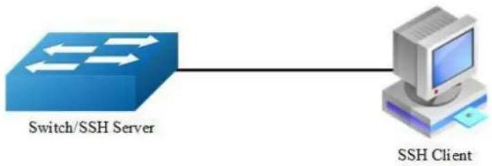
The Secure Shell (SSH) is a protocol that provides a secure, remote connection to a device. SSH provides more security for remote connections than Telnet does by providing strong encryption when a device is authenticated. SSH supports the Data Encryption Standard (DES) encryption algorithm, the Triple DES (3DES) encryption algorithm, and password-based user authentication. The SSH feature has an SSH server and an SSH integrated client, which are applications that run on the switch. You can use an SSH client to connect to a switch running the SSH server. The SSH server works with the SSH client supported in this release and with SSH clients. The SSH client also works with the SSH server supported in this release and with SSH servers.
Principle Description
N/A
2.8.2 Configuration
flowchart
graph LR
    A["Switch/SSH Server"] --> B["SSH Client"]
    style A fill:#333,stroke:#fff,color:#fff
    style B fill:#f9f,stroke:#000,stroke-width:2px
Figure 2-1 SSH system application
Create key for SSH
step 1 Enter the configure mode
Switch# configure terminal
step 2 Create a key
Switch(config)# rsa key a generate
step 3 Create a private key named a.pri with key a and save it to flash
Switch(config)# rsa key a export url flash:/a.pri private ssh2
step 4 Create a private key named a.pub with key a and save it to flash
Switch(config)# rsa key a export url flash:/a.pub public ssh2
step 5 Exit the configure mode
Switch(config)# exit
Import the key
step 1 Enter the configure mode
Switch# configure terminal
step 2 Import the key a.pub we created as importKey
Switch(config)# rsa key importKey import url flash:/a.pub public ssh2
step 3 Create username and password
Switch(config)# username aaa privilege 4 password abc
step 4 Assign the key to user aaa
Switch(config)# username aaa assign rsa key importKey
step 5 Exit the configure mode
Switch(config)# exit
Use SSH to connect
step 1 Download the a.pri key on SSH client
step 2 Connect to the client
[root@test1 tftpboot]# ssh -i a.pri aaa@10.10.39.101
aaa@10.10.39.101's password:
Switch#
2.8.3 Application cases
N/A
2.9 Configuring Time&timezone
2.9.1 Overview
Function Introduction
If no other source of time is available, you can manually configure the time and date after the system is restarted. The time remains accurate until the next system restart. We recommend that you use manual configuration only as a last resort. If you have an outside source to which the switch can synchronize, you do not need to manually set the system clock.
Principle Description
N/A
2.9.2 Configuration
step 1 Enter the configure mode
Switch# configure terminal
step 2 Configuring time and timezone
Switch(config)# clock set datetime 11:30:00 10 26 2013
Switch(config)# clock set summer-time dst date 6 1 2013 02:00:00 10 31 2013 02:00:00 120
step 3 Exit the configure mode
Switch(config)# exit
step 4 Validation
Use the following command to display the information of time and date:
Switch# show clock detail
13:31:10 dst Sat Oct 26 2013
Time zone: (GMT + 08:00:00) beijing
Summer time starts at beijing 02:00:00 06/01/2013
Summer time ends at dst 02:00:00 10/31/2013
Summer time offset: 120 minutes
2.9.3 Application cases
N/A
2.10 Configuring License
2.10.1 Overview
Function Introduction
License will control the features on the switch; each switch has its own license to avoid the unauthorized user to use the advanced features. There are totally three kinds of licenses: Enterprise Base, Metro Service, and Metro Advanced. Different license will contain different features. Customer can apply different license to satisfy different requirement. If switch has no license, it can only provide L2 features. Different switch can't share the same license. In order to get the license for the specify switch, first generate the unique device identifier(UDI) for the switch and then send the UDI to vendor to apply the license, at last get the license from vendor and use the license on the switch.
Principle Description
N/A
2.10.2 Configuration
step 1 Create UDI for the device and send it to remote FTP server
Switch# generate device identifier mgmt-if ftp://test:test@10.10.25.33/device.udi
step 2 Apply license
Send UDI file to vendor, vendor will generate license for customer requirement.
step 3 Use license
Get the license to local from remote FTP server, and reload the system.
Switch# copy mgmt-if ftp://test:test@10.10.25.33/device.lic flash:/device.lic
Switch# reload

NOTE
You must reload the switch for the license to take effect.
If the switch has no license, it can only work with L2 features.
If the switch has more than one license, all the features contain by the licenses can take effect
step 4 Validation
Use the following command to display the information of the license:
Switch# show license
License files:
flash:/ma.lic:
Created Time: Fri Dec 6 17:22:23 CST 2013
Vendor: switchVendor
Customer: switchCustomer
Device MAC: 00:1E:08:09:03:00
Feature Set: QINQ MVR ERPS MEF ETHOAM
VPWS VPLS HVPLS SMLK TPOAM
OSPF PIM_SM IGMP VRF MPLS
LDP BGP RSVP OSPF_TE EXTEND_ACL
PTP BFD SSM IPV6 OSPF6
PIM_SM6 MVR6 RIPNG TUNNEL_V6
2.11 RPC API Configuration Guide
2.11.1 Overview
Function Introduction
RPC API service allows user to configure and monitor the switch system through Remote Procedure Calls (RPC) from your program.
The service currently supports JSON-RPC over HTTP protocol together with HTTP Basic authentication.
Principle Description
RPC API service uses standard JSON-RPC over HTTP protocol to communicate the switch and your program. User may issue switch CLI commands through JSON-RPC method: 'executeCmds'. By default, the CLI mode is in privileged EXEC mode (#).
User could send JSON-RPC request via an HTTP POST request to URL: http://command-api. The detailed JSON-RPC request and response are show below:
JSON-RPC Request
{
    "params": [
    {
    "format":"text",
    can be 'text' or 'json',
    the default format is 'text'
    "version":1,
    "cmds": [
    "show run",
    "config t",
    "vlan database",
    "vlan 1-8",
    "interface eth-0-1",
    "switchport mode trunk",
    "switchport trunk allowed vlan add 2",
    "shutdown",
    "end",
    "show interface switchport"
    ]
    }
    ],
    Parameters for command
    Expected response format,
    The API version
    List of CLI commands
    CLI command 1
    CLI command 2
    CLI command 3
    CLI command 4
    CLI command 5
    CLI command 6
    CLI command 7
    CLI command 8
    CLI command 9
    CLI command 10
"jsonrpc":"2.0", JSON RPC protocol version.
Always 2.0.
"method":"executeCmds", Method to run the switch
CLI commands
"id":"70853aff-af77-420e-8f3c-fa9430733a19" JSON RPC unique identifier
}
JSON-RPC Response
{
    "jsonrpc":"2.0", JSON RPC protocol version.
Always 2.0.
    "id":"70853aff-af77-420e-8f3c-fa9430733a19", JSON RPC unique identifier
    "result":[ Result list of objects from each CLI command executed.
    {
    "sourceDetails":"version 5.1.6.fcs\n!\n ...", Output information of CLI
Command 1.
    The Original ASCII output information returned from CLI command if this command is successfully executed.
    "errorCode":-1003, Error code if it is available.
    "errorDesc":"unsupported command...", Error description if it is available.
    "warnings":"% Invalid...", Warnings if it is available.
    Formatted JSON object will also be returned if it is available.
    },
    { }, Output information of CLI
Command 2.
    { }, Output information of CLI
Command 3.
    { }, Output information of CLI
Command 4.
    { }, Output information of CLI
Command 5.
    { }, Output information of CLI
Command 6.
    { }, Output information of CLI
Command 7.
    { }, Output information of CLI
Command 8.
    { }, Output information of CLI
Command 9.
    {
    "sourceDetails":" Interface name : eth-0-1\n Switchport mode : trunk\n ...\n"
    }
    Output information of CLI
Command 10.
    ]
}
Python Client Example Code
Here is an example code using 'pyjsonrpc' library:
import pyjsonrpc
import json

http_client = pyjsonrpc.HttpClient(
    url = "http://10.10.39.64:80/command-api",
    username = "username",
    password = "password"
)

cmds = {}
cmd_list = ["show run", "config t", "vlan database", "vlan 1-8", "interface eth-0-1", "switchport mode trunk", "switchport trunk allowed vlan add 2", "shutdown", "end", "show interface switchport"]

cmds['cmds'] = cmd_list
cmds['format'] = 'text'
cmds['version'] = 1

try:
    response = http_client.call("executeCmds", cmds)
    print("json response:");
    json_result = json.dumps(response, indent=4)
    print(json_result)
except Exception, e:
    if e.code == 401:
    print "Unauthorized user"
    else:
    print e.message
    print e.data
Error code
Here is a list of JSON-RPC 2.0 error code:
| Error Code | Description |
| -32700 | Parse error |
| -32600 | Invalid Request |
| -32601 | Method not found |
| -32602 | Invalid param |
| -32603 | Internal error |
Here is a list of RPC-API error code:
| Error Code | Description |
| -1000 | General error |
| -2001 | JSON RPC API Error: unsupported API version |
| -2002 | JSON RPC API Error: must specify ‘params’ with ‘cmds’ in JSON RPC |
| -2003 | JSON RPC API Error: unsupported command response format |
| -3001 | Command execution failed: timed out |
| -3002 | Command execution failed: unsupported command |
| -3003 | Command execution failed: unauthorized command |
| -3004 | Command execution failed: the string does not match any command in current mode |
| -3005 | Command execution failed: can’t convert to JSON format |
| -3006 | Command execution failed: command list too short |
| -3007 | Command execution failed: command list too long |
2.11.2 Configuration
Configuring RPC API service
User could enable the RPC API service by the following steps.
The default port is 80.
step 1 Enter the configure mode
Switch# configure terminal
step 2 Enable RPC API service
Switch(config)# service rpc-api enable

NOTE
Use the following command to disable rpc-api service:
Switch(config)# service rpc-api disable
step 3 Exit the configure mode
Switch(config)# end
Configuring RPC API service with HTTP Authentication
User could configure the HTTP authentication mode of RPC API service.
Currently, only HTTP Basic authentication is supported. User will receive status code: 401 (Unauthorized access) if user provides invalid user name or password.
step 1 Enter the configure mode
Switch# configure terminal
Step 2 Set the username and password, then enable the rpc-api authentication
Switch(config)# username myuser password mypass privilege 4 Switch(config)# service rpc-api auth-mode basic

NOTE
Use the following command to disable authentication:
Switch(config)# no service rpc-api auth-mode

NOTE
HTTP authentication settings of RPC API service will take effect at this service or reboot the system.
step 3 Exit the configure mode
Switch(config)# end
step 4 Validation
Switch# show services rpc-api
RPC API service configuration:
Server State : enable
Port : 80
Authentication Mode : basic
VRF : default
2.11.3 Application cases
N/A
2.12 Configuring HTTP
2.12.1 Overview
Function Introduction
This chapter describes how to configure the switch to start the Web management function.
Principle Description
N/A
2.12.2 Configuration
Preparatory
Put a valid web image to flash: directory. Please reference to FTP or TFTP guide.
Configure HTTP server
step 1 Enter the configure mode
Switch# configure terminal
step 2 Load WEB image
Switch(config)# http server load flash:/webImage.bin
step 3 Configure HTTP server address (Optional)
Use this step to specify the source address of WEB http server, only loopback address is supported. If the source address of WEB http server is specified, it will be the only address to access the WEB. If the source address of WEB http server is not specified, user can access the WEB via the same address as telnet. The route between the device and the client is necessary.
Switch(config)# interface loopback 0
Switch(config-if)# ip address 192.168.1.100/32
Switch(config-if)# quit
Switch(config)# http server source address 192.168.1.100
This operation will cause all the online HTTP(S) users to be offline.
Continue? [yes/no]: yes
Switch(config)# ip route 0.0.0.0/0 192.168.1.1
step 4 Enable HTTP service
Switch(config)# service http enable
This operation will cause all the online HTTP(S) users to be offline.
Continue? [yes/no]: yes
step 5 Exit the configure mode
Switch(config)# exit
step 6 Login the web via the browser
Enter the IP address to login the web.
2.12.3 Application cases
N/A
3 Ethernet Configuration Guide
3.1 Configuring Interface
3.1.1 Overview
Function Introduction
Interface status, speed and duplex are configurable.
When the interface is configured as “no shutdown”, it can work normally after cable is connected. When the interface is configured as “shutdown”, no matter the cable is connected or not, the interface can not work.
If the device supports combo ports, user can choose to enable copper or fiber mode. The two modes of one port can not work together at same time. The configuration of speed or duplex at combo ports cannot be effective when combo port is working at fiber mode.
The rule of physical port name is as following: interface name format is eth-[slot]-[port]; [slot] is 0 for single pizza-box switch; when stacking is enabled, the [slot] number is according to the configuration. The [port] number is begin with 1, and increase from up to down, from left to right. The following figure shows the interface name of the device:
| eth-0-1 | eth-0-3 | ... | eth-0-23 |
| eth-0-2 | eth-0-4 | ... | eth-0-24 |
Figure 3-1 Interface Name

NOTE
To get more information about the interface type and number,
please reference to the product spec.
Principle Description
N/A
3.1.2 Configuration
Configuring Interface State
step 1 Enter the configure mode
Switch# configure terminal
step 2 Turn on an interface
Switch# (config)# interface eth-0-1
Switch(config-if)# no shutdown
step 3 Shut down an interface
Switch(config-if)# interface eth-0-2
Switch(config-if)# shutdown
step 4 Exit the configure mode
Switch(config-if)# end
step 5 Validation
Use the following command to display the status of the interfaces:
| Switch# show interface status | |||||
| Port | Status | Duplex | Speed | Mode | Type |
| eth-0-1 | up | a-full | a-1000 | access | 1000BASE_T |
| eth-0-2 | admin down auto | auto | access | 1000BASE_T | |
Configuring Interface Speed
step 1 Enter the configure mode
Switch# configure terminal
step 2 Enter the interface configure mode and set the speed
Set speed of interface eth-0-1 to 100M
Switch(config)# interface eth-0-1
Switch(config-if)# speed 100
Switch(config-if)# no shutdown
Set speed of interface eth-0-2 to 1000M
Switch(config-if)# interface eth-0-2
Switch(config-if)# no shutdown
Switch(config-if)# speed 1000
Set speed of interface eth-0-3 to auto
Switch(config-if)# interface eth-0-3
Switch(config-if)# no shutdown
Switch(config-if)# speed auto
step 3 Exit the configure mode
Switch(config-if)# end
step 4 Validation
Use the following command to display the status of the interfaces:
| Switch# show interface status | |||||
| Port | Status | Duplex | Speed | Mode | Type |
| eth-0-1 | up | a-full | 100 | access | 1000BASE_T |
| eth-0-2 | up | a-full | 1000 | access | 1000BASE_T |
| eth-0-3 | up | a-full | a-1000 | access | 1000BASE_T |
Configuring Interface Duplex
There are 3 duplex mode supported on the device:
full mode: the interface can transmit and receive packets at same time.
half mode: the interface can transmit or receive packets at same time.
auto mode: the interface should negotiate with the other side to decide the duplex mode.
User can choose proper duplex mode according to the network state.
step 1 Enter the configure mode
Switch# configure terminal
step 2 Enter the interface configure mode and set the duplex
Set duplex of interface eth-0-1 to full
Switch(config)# interface eth-0-1
Switch(config-if)# no shutdown
Switch(config-if)# duplex full
Set duplex of interface eth-0-1 to half
Switch(config-if)# interface eth-0-2
Switch(config-if)# no shutdown
Switch(config-if)# duplex half
Set duplex of interface eth-0-1 to auto
Switch(config)# interface eth-0-3
Switch(config-if)# no shutdown
Switch(config-if)# duplex auto
step 4 Validation
Use the following command to display the status of the interfaces:
| Switch# show interface status | |||||
| Port | Status | Duplex | Speed | Mode | Type |
| eth-0-1 | up | full | a-1000 | access | 1000BASE_T |
| eth-0-2 | up | half | a-100 | access | 1000BASE_T |
| eth-0-3 | up | a-full | a-1000 | access | 1000BASE_T |
3.1.3 Application cases
N/A
3.2 Configuring Layer3 Interfaces
3.2.1 Overview
Function Introduction
3 types of Layer3 interface are supported:
VLAN interfaces: Logical interface with layer3 features. Connect different VLANs via IP address on the VLAN interface. VLAN interfaces can be created and deleted.
Routed Ports: Ports are physical ports configured to be in Layer 3 mode by using the no switchport in interface configuration command.
Layer 3 Link Aggregation Ports: Link Aggregation interfaces made up of routed ports.
A Layer 3 switch can have an IP address assigned to each routed port and VLAN interface. All Layer 3 interfaces require an IP address to route traffic. This section shows how to configure an interface as a Layer 3 interface and how to assign an IP address to an interface.
Principle Description
N/A
3.2.2 Configuration
Configuring Routed Port
step 1 Enter the configure mode
Switch# configure terminal
step 2 Enter the interface configure mode and set IP address
Switch(config)# interface eth-0-1
Switch(config-if)# no switchport
Switch(config-if)# no shutdown
Switch(config-if)# ip address 1.1.1.1/24
step 3 Exit the configure mode
Switch(config-if)# end
step 4 Validation
Use the following command to display the brief status of the interfaces:
Switch# show ip interface brief
Interface IP-Address Status Protocol
eth-0-1 1.1.1.1 up up
Switch# show ip interface
Interface eth-0-1
Interface current state: UP
Internet address(es):
1.1.1.1/24 broadcast 1.1.1.255
Joined group address(es):
224.0.0.1
The maximum transmit unit is 1500 bytes
ICMP error messages limited to one every 1000 milliseconds
ICMP redirects are always sent
ICMP unreachables are always sent
ICMP mask replies are always sent
ARP timeout 01:00:00, ARP retry interval ls
VRRP master of: VRRP is not configured on this interface
Configuring VLAN Interfaces
This chapter describes configuring VLAN interfaces and using them. Several Virtual LAN (VLAN) interfaces can be configured on a single Ethernet interface. Once created, a VLAN interface functions the same as any physical interface, and it can be configured and displayed like any physical interface. Routing protocols, such as, RIP, OSPF and BGP can run across networks using VLAN interfaces.
step 1 Enter the configure mode
Switch# configure terminal
step 2 Enter the vlan configure mode and create a vlan
Switch(config)# vlan database
Switch(config-vlan)# vlan 10
Switch(config-vlan)# exit
step 3 Enter the interface configure mode and set switch port attributes
Switch(config)# interface eth-0-2
Switch(config-if)# switchport mode trunk
Switch(config-if)# switchport trunk allowed vlan all
Switch(config-if)# no shutdown
Switch(config-if)# exit
step 4 Enter the vlan interface configure mode and set IP address
Switch(config)# interface vlan10
Switch(config-if)# ip address 2.2.2.2/24
step 5 Exit the configure mode
Switch(config-if)# end
step 6 Validation
Use the following command to display the brief status of the interfaces:
Switch# show ip interface brief
Interface IP-Address Status Protocol
vlan10 2.2.2.2 up up
Switch# show ip interface
Interface vlan10
Interface current state: UP
Internet address(es):
2.2.2.2/24 broadcast 2.2.2.255
Joined group address(es):
224.0.0.1
The maximum transmit unit is 1500 bytes
ICMP error messages limited to one every 1000 milliseconds
ICMP redirects are always sent
ICMP redirects are always sent
ICMP unreachables are always sent
ICMP mask replies are always sent
ARP timeout 01:00:00, ARP retry interval ls
VRRP master of : VRRP is not configured on this interface
3.3 Configuring Interface Errdisable
3.3.1 Overview
Function Introduction
Errdisable is a mechanism to protect the system through shutdown the abnormal interface. If an interface enters errdisable state, there are two ways to recovery it from errdisabled state. The first one is to enable errdisable recovery of this reason before errdisable detection; the interface will be recovered automatically after the configured time. But if errdisable occurred first, then errdisable recovery is enabled, the errdisable will not be recovered automatically. The secondary one is configuring “no shutdown” command on the errdisabled interface.
The flap of interface link state is a potential error caused by hardware or line problem. The administrator can also configure the detection conditions of interface link flap to suppress the flap.
Principle Description
N/A
3.3.2 Configuration
Configuring Errdisable Detection
step 1 Enter the configure mode
Switch# configure terminal
step 2 Enable detect link flap errdisable
Switch(config)# errdisable detect reason link-flap
step 3 Exit the configure mode
Switch(config)# end
step 4 Validation
Use the following command to display the configuration of error disable:
Switch# show errdisable detect
ErrDisable Reason Detection status
bpduguard Enabled
bpduloop Enabled
link-monitor-failure Enabled
oam-remote-failure Enabled
port-security Enabled
link-flap Enabled
monitor-link Enabled
udld Disabled
fdb-loop Disabled
loopback-detection Enabled
reload-delay Enabled
Configuring Errdisable Recovery
step 1 Enter the configure mode
Switch# configure terminal
step 2 Enable errdisable and set recovery interval
Switch(config)# errdisable recovery reason link-flap
Switch(config)# errdisable recovery interval 30
step 3 Exit the configure mode
Switch(config)# end
step 4 Validation
Use the following command to display the configuration of error disable recovery:
Switch# show errdisable recovery
ErrDisable Reason Timer Status
bpduguard Disabled
bpduloop Disabled
link-monitor-failure Disabled
oam-remote-failure Disabled
port-security Disabled
link-flap Enabled
udld Disabled
fdb-loop Disabled
loopback-detection Disabled
Timer interval: 30 seconds
Configuring suppress Errdisable link Flap
step 1 Enter the configure mode
Switch# configure terminal
step 2 Set link flap condition
Switch(config)# errdisable flap reason link-flap 20 60
step 3 Exit the configure mode
Switch(config)# end
step 4 Validation
Use the following command to display the configuration of error disable flap:
Switch# show errdisable flap
ErrDisable Reason Flaps Time (sec)
link-flap 20 60
Checking Errdisable Status
Administrator can check the interface errdisable status though two commands.
Case 1 Enable errdisable recovery
If link flap errdisable is enabled recovery, the command will display the left time for recovery; Otherwise, will display "unrecovery".
Switch# show errdisable recovery
ErrDisable Reason Timer Status

bpduguard Disabled
bpduloop Disabled
link-monitor-failure Disabled
oam-remote-failure Disabled
port-security Disabled
link-flap Enabled
udld Disabled
fdb-loop Disabled
loopback-detection Disabled
Timer interval: 300 seconds
Interfaces that will be enabled at the next timeout:
Interface Errdisable Reason Time Left(sec)

eth-0-3 link-flap 25
Case 2 Disalbe errdisable recovery
Switch# show errdisable recovery
ErrDisable Reason Timer Status
bpduguard Disabled
bpduloop Disabled
link-monitor-failure Disabled
oam-remote-failure Disabled
port-security Disabled
link-flap Disabled
udld Disabled
fdb-loop Disabled
loopback-detection Disabled
Timer interval: 300 seconds
case 3 Display interface brief information to check errdisable state.
Switch# show interface status
Port Status Duplex Speed Mode Type Description
| eth-0-1 | up | a-full | a-1000 | TRUNK | 1000BASE_SX |
| eth-0-2 | down | auto | auto | TRUNK | Unknown |
| eth-0-3 | errdisable | a-full | a-1000 | TRUNK | 1000BASE_SX |
| eth-0-4 | down | auto | auto | ACCESS | Unknown |
3.3.3 Application cases
N/A
3.4 Configuring MAC Address Table
3.4.1 Overview
Function Introduction
MAC address table contains address information for the switch to forward traffic between ports. The address table includes these types of address:
Dynamic address: the source address learnt by the switch and will be aged after aging time if this address is not hit. We only support IVL learning mode.
Static address: the source address manually added by administrators.
Following is a brief description of terms and concepts used to describe the MAC address table:
IVL: Independent VLAN Learning: for a given set of VLANs, if a given individual MAC Address is learned in one VLAN, it can't be used in forwarding decisions taken for that address relative to any other VLAN in the given set.
SVL: Shared VLAN Learning: for a given set of VLANs, if an individual MAC Address is learned in one VLAN, it can be used in forwarding decisions taken for that address relative to all other VLANs in the given set.
Reference to standard: IEEE 802.1D, IEEE 802.1Q
Principle Description
N/A
3.4.2 Configuration
Configuring Address Aging Time
flowchart
graph LR
    A["Router"] -->|eth -0-1| B["Computer"]
    B --> C["0000.1111.2222"]
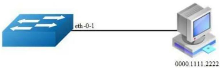
Figure 3-2 Mac address aging
The aging time is not exact time. If aging time set to N, then the dynamic address will be aged after N\~2N interval. The default aging time is 300 seconds.
step 1 Enter the configure mode
Switch# configure terminal
step 2 Set dynamic address aging time
Switch(config)# mac-address-table ageing-time 10
step 3 Exit the configure mode
Switch(config)# end
step 4 Validation
Use the following command to display the aging time:
Switch# show mac address-table ageing-time MAC address table ageing time is 10 seconds
Configuring Static Unicast Address
flowchart
graph TD
    A["eth-0-1"] -->|eth-0-2| B["0000.AAAA.AAAA"]
    C["0000.1234.5678"] --> A
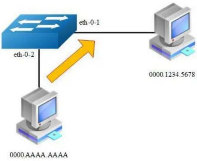
Figure 3-3 Static mac address table
Unicast address can be only bound to one port. According to the picture, Mac-Da 0000.1234.5678 should forward via eth-0-1.
step 1 Enter the configure mode
Switch# configure terminal
step 2 Set static mac address table
Switch(config)# mac-address-table 0000.1234.5678 forward eth-0-1 vlan 1
step 3 Exit the configure mode
Switch(config)# end
step 4 Validation
Use the following command to display the mac address table:
Switch# show mac address-table
Mac Address Table
(*)- Security Entry
Vlan Mac Address Type Ports
1 0000.1234.5678 static eth-0-1
Configuring Static Multicast Address
flowchart
graph TD
    A["Server"] -->|eth-0-3| B["Server"]
    B -->|eth-0-1| C["Computer 1"]
    B -->|eth-0-2| D["Computer 2"]
    C --> E["0100.0000.0000"]
    D --> E
Figure 3-4 Static multicast mac address table
Multicast address can be bound to multi-port. According to the picture, Mac-Da 0100.0000.0000 can forward via eth-0-1 and eth-0-2.
step 1 Enter the configure mode
Switch# configure terminal
step 2 Set static multicast mac address table
Switch(config)# mac-address-table 0100.0000.0000 forward eth-0-1 vlan 1
Switch(config)# mac-address-table 0100.0000.0000 forward eth-0-2 vlan 1
step 3 Exit the configure mode
Switch(config)# end
step 4 Validation
Use the following command to display the mac address table:
Switch# show mac address-table
Mac Address Table

(*) - Security Entry
Vlan Mac Address Type Ports
1 0100.0000.0000 static eth-0-1
eth-0-2
Configuring MAC Filter Address
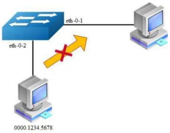
flowchart
graph TD
    A["eth-0-2"] -->|eth-0-1| B["Computer"]
    C["0000.1234.5678"] -->|red X| A
Figure 3-5 mac address filter
MAC filter will discard these frames whose source or destination address is set to discard. The MAC filter has higher priority than MAC address.
step 1 Enter the configure mode
Switch# configure terminal
step 2 Add unicast address to be discarded
Switch(config)# mac-address-table 0000.1234.5678 discard
step 3 Exit the configure mode
Switch(config)# end
step 4 Validation
Use the following command to display the mac address filter:
Switch# show mac-filter address-table
MAC Filter Address Table
Current count : 1
Max count : 128
Left count : 127
Filter address list :
0000.1234.5678
3.4.3 Application cases
N/A
3.5 Configuring VLAN
3.5.1 Overview
Function Introduction
VLAN (Virtual Local Area Network) is a switched network that is logically segmented the network into different broadcast domain so that packets are only switched between ports that are designated for the same VLAN. Each VLAN is considered as a logical network, and packets send to stations that do not belong to the same VLAN must be forwarded through a router.
Reference to standard: IEEE 802.1Q
Principle Description
Following is a brief description of terms and concepts used to describe the VLAN:
VID: VLAN identifier
LAN: Local Area Network
VLAN: Virtual LAN
PVID: Port VID, the untagged or priority-tagged frames will be assigned with this VID
Tagged Frame: Tagged Frame is inserted with 4 Bytes VLAN Tag, show in the picture below:
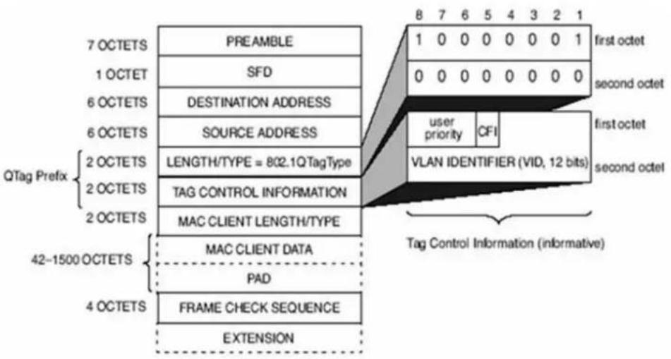
Figure 3-6 Tagged Frame
Trunk Link: Both tagged and untagged frames can be transmitted on this link. Trunk link allow for multiple VLANs to cross this link, show in the picture below:

flowchart
graph LR
    A["Switch1"] -->|VLAN tagged frame| B["Switch2"]
    B -->|VLAN untagged frame| A
Figure 3-7 Trunk link
Access Link: Only untagged frames can be transmitted on this link. Access link is at the edge of the network, where end stations attach, show in the picture below:
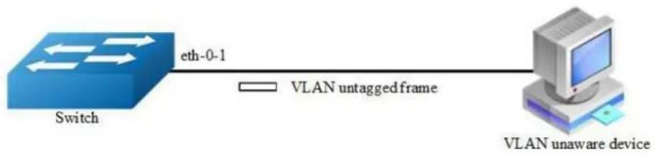
flowchart
graph LR
    A["Switch"] -->|eth-0-1| B["VLAN untagged frame"]
    B --> C["VLAN unaware device"]
Figure 3-8 Access link
3.5.2 Configuration
Configuring Access Port
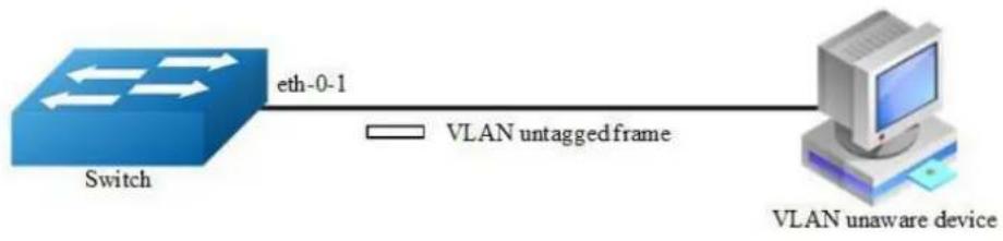
flowchart
graph LR
    A["Switch"] -->|eth-0-1| B["VLAN untagged frame"]
    B --> C["VLAN unaware device"]
Figure 3-9 Access link
Access port only receives untagged or priority-tagged frames, and transmits untagged frames.
step 1 Enter the configure mode
Switch# configure terminal
step 2 Enter the vlan configure mode and create vlan
Switch(config)# vlan database
Switch(config-vlan)# vlan 2
Switch(config-vlan)# exit
step 3 Enter the interface configure mode, set the switch port mode and bind to the vlan
Switch(config)# interface eth-0-1
Switch(config-if)# switchport mode access
Switch(config-if)# switchport access vlan 2
step 4 Exit the configure mode
Switch(config-if)# end
step 5 Validation
Use the following command to display the information of the switch port interface:
Switch# show interface switchport interface eth-0-1
Interface name : eth-0-1
Switchport mode : access
Ingress filter : enable
Acceptable frame types : vlan-untagged only
Default Vlan : 2
Configured Vlans : 2
Use the following command to display the vlan brief information:
Switch# show vlan brief
VLAN ID Name State STP ID Member ports
(u)-Untagged, (t)-Tagged
1 default ACTIVE 0 eth-0-2(u) eth-0-3(u)
eth-0-4(u) eth-0-5(u)
eth-0-6(u) eth-0-7(u)
eth-0-8(u) eth-0-9(u)
eth-0-10(u) eth-0-11(u)
eth-0-12(u) eth-0-13(u)
eth-0-14(u) eth-0-15(u)
eth-0-16(u) eth-0-17(u)
eth-0-18(u) eth-0-19(u)
eth-0-20(u) eth-0-21(u)
eth-0-22(u) eth-0-23(u)
2 VLAN0002 ACTIVE 0 eth-0-1(u)
Configuring Trunk Port
Trunk port receives tagged, untagged, and priority-tagged frames, and transmits both untagged and tagged frames. If trunk port receives an untagged frame, this frame will be assigned to the VLAN of the trunk port's PVID; if a frame send out from the trunk port and the frame's VID is equal to the trunk port's PVID, this frame will be send out without VLAN tag.
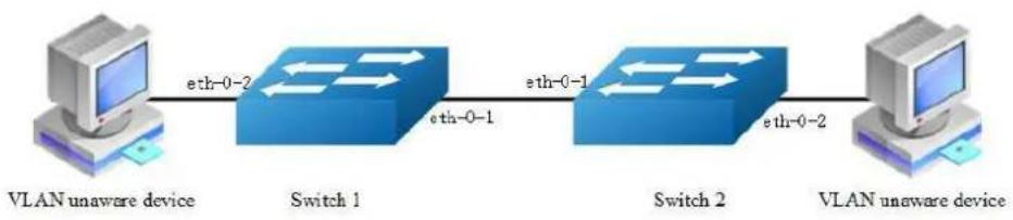
flowchart
graph LR
    A["VLAN unaware device"] -->|eth-0-2| B["Switch 1"]
    B -->|eth-0-1| C["Switch 2"]
    C -->|eth-0-2| D["VLAN unaware device"]
Figure 3-10 Trunk link
Network topology is shown in the picture above. The following configuration steps are same for Switch1 and Switch2.
step 1 Enter the configure mode
Switch# configure terminal
step 2 Enter the vlan configure mode and create vlan
Switch(config)# vlan database
Switch(config-vlan)# vlan 10,20
Switch(config-vlan)# exit
step 3 Enter the interface configure mode, set the switch port mode and bind to the vlan
Set eth-0-1's switch port mode as trunk, set native vlan as 10, and allow all VLANs on this interface:
Switch(config)# interface eth-0-1
Switch(config-if)# switchport mode trunk
Switch(config-if)# switchport trunk allowed vlan all
Switch(config-if)# switchport trunk native vlan 10
Switch(config-if)# exit
Set eth-0-2's switch port mode as access, and bind to vlan 10:
Switch(config)# interface eth-0-2
Switch(config-if)# switchport mode access
Switch(config-if)# switchport access vlan 10
Switch(config-if)# exit
step 4 Exit the configure mode
Switch(config-if)# end
step 5 Validation
Use the following command to display the information of the switch port interface:
Switch# show interface switchport
Interface name : eth-0-1
Switchport mode : trunk
Ingress filter : enable
Acceptable frame types : all
Default Vlan : 10
Configured Vlans : 1 10 20
Interface name : eth-0-2
Switchport mode : access
Ingress filter : enable
Acceptable frame types : vlan-untagged only
Default Vlan : 10
Configured Vlans : 10
Use the following command to display the vlan brief information:
Switch# show vlan brief
VLAN ID Name State STP ID Member ports
(u)-Untagged, (t)-Tagged
1 default ACTIVE 0 eth-0-1(t) eth-0-3(u)
    eth-0-4(u) eth-0-5(u)
    eth-0-6(u) eth-0-7(u)
    eth-0-8(u) eth-0-9(u)
    eth-0-10(u) eth-0-11(u)
    eth-0-12(u) eth-0-13(u)
    eth-0-14(u) eth-0-15(u)
    eth-0-16(u) eth-0-17(u)
    eth-0-18(u) eth-0-19(u)
    eth-0-20(u) eth-0-21(u)
    eth-0-22(u) eth-0-23(u)
10 VLAN0010 ACTIVE 0 eth-0-1(t) eth-0-2(u)
20 VLAN0020 ACTIVE 0 eth-0-1(t)
3.5.3 Application cases
N/A
3.6 Configuring Voice VLAN
3.6.1 Overview
Function Introduction
With the development of the voice technology, the use of IP Phone/IAD(Integrated Access Device) is becoming more and more widespread in broadband community. Voice and data traffics are usually present in the network at the same time, therefore, voice traffics need higher priority to improve the performance and reduce the packet loss rate.
The traditional method to improve the quality of voice traffic is using ACL to separate the voice packets, and using QoS to ensure the transmit quality.
The voice VLAN feature can identify the voice packets by source mac, which makes the conguration more convenient.
Principle Description
N/A
3.6.2 Configuration
step 1 Enter the configure mode
Switch# configure terminal
step 2 Enter the vlan configure mode and create vlan
Switch(config)# vlan database
Switch(config-vlan)# vlan 2
Switch(config-vlan)# exit
step 3 Set the cos of voice vlan (Optional)
The default cos is 5.
Switch(config)# voice vlan set cos to 7
step 4 Set the voice vlan and create a mac entry for it
Switch(config)# voice vlan 2
Switch(config)# voice vlan mac-address 0055.0000.0000 ffff.ff00.0000 description test
step 5 Enter the interface configure mode and enable voice vlan
Switch(config)# interface eth-0-1
Switch(config-if)# switchport mode trunk
Switch(config-if)# switchport trunk allowed vlan all
Switch(config-if)# voice vlan enable
Switch(config-if)# interface eth-0-2
Switch(config-if)# switchport mode trunk
Switch(config-if)# switchport trunk allowed vlan all
step 6 Validation
Send packet to eth-0-1, the format of the packet is as below (priority in Vlan tag is 0)
:
0x0000: 0000 0a02 0001 0055 0000 0011 8100 0002 ....k.....
0x0010: 0800 aadd aadd aadd aadd aadd aadd aadd .....
0x0020: aadd aadd aadd aadd aadd aadd aadd aadd .....
0x0030: aadd aadd aadd aadd aadd aadd ....
Receive packet from eth-0-2, the format of the packet received is as below (priority in Vlan tag is 5):.
0x0000: 0000 0a02 0001 0055 0000 0011 8100 a002 ....k.....
0x0010: 0800 aadd aadd aadd aadd aadd aadd aadd .....
0x0020: aadd aadd aadd aadd aadd aadd aadd aadd .....
0x0030: aadd aadd aadd aadd aadd aadd ....
3.6.3 Application cases
N/A
3.7 Configuring VLAN Classification
3.7.1 Overview
Function Introduction
VLAN classification is used to define specific rules for directing packets to selected VLANs based on protocol or subnet criteria. Sets of rules can be grouped (one group per interface).
VLAN classification rules have 3 types: mac based, ip based and protocol based. MAC based vlan classification rule will classify packets to specified VLAN according to the source MAC address of incoming packets; IP based vlan classification rule will classify packets according to the source IP address of incoming packets; And protocol based vlan classification rule will classify packets according to the layer3 type of incoming packets. The following layer3 types can be supported: ARP, IP(v4), MPLS, Mcast MPLS, PPPoE, RARP.
Different types of vlan classification rules can be added to same vlan classification group. VLAN classification group can only be applied on switchport. Only one type of vlan classification rules can take effect on one switchport.
Principle Description
N/A
3.7.2 Configuration
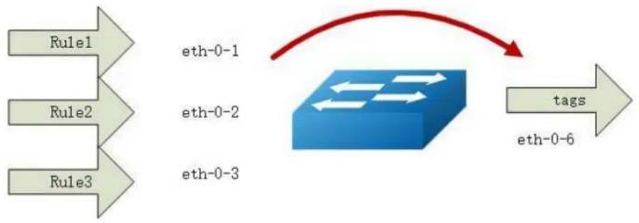
flowchart
graph LR
    A["Rule1"] --> B["eth-0-1"]
    C["Rule2"] --> D["eth-0-2"]
    E["Rule3"] --> F["eth-0-3"]
    G["tags"] --> H["eth-0-6"]
Figure 3-11 vlan classification
In this configuration example, three VLAN classifier rules are created:
Rule 1 is mac based rule, it will classify the packets with MACSA 2222.2222.2222 to vlan 5;
Rule 2 is ip based rule, it will classify the packets sourced from IP adress 1.1.1.1/24 to vlan 5;
Rule 3 is protocol based rule, it will classify all arp packets to vlan 5.
Add rule 1, rule2, rule3 to group 31. Then apply group 31 to 3 interfaces: eth-0-1, eth-0-2, eth-0-3. These 3 interfaces have different vlan classification type. eth-0-1 is configured to ip based vlan class, this means only ip based rules can take effect on this interface. eth-0-2 is configured to mac based vlan class, this means only mac based rules can take effect on this interface. eth-0-3 is configured to protocol based vlan class, this means only protocol based rules can take effect on this interface.
step 1 Enter the configure mode
Switch# configure terminal
step 2 Enter the vlan configure mode and create vlan
Switch(config)# vlan database
Switch(config-vlan)# vlan 5
Switch(config-vlan)# vlan 6
Switch(config-vlan)# exit
step 3 Create vlan classifier rule and add the rules to the group
Switch(config)# vlan classifier rule 1 mac 2222.2222.2222 vlan 5
Switch(config)# vlan classifier rule 2 ip 1.1.1.1 vlan 5
Switch(config)# vlan classifier rule 3 protocol arp vlan 5

Switch(config)# vlan classifier group 31 add rule 1
Switch(config)# vlan classifier group 31 add rule 2
Switch(config)# vlan classifier group 31 add rule 3
Switch(config)# arp as-layer-3 enable
step 4 Apply the vlan classifier group on the interface
interface eth-0-1:
Switch(config)# interface eth-0-1
Switch(config-if)# switchport access vlan 6
Switch(config-if)# switchport access allowed vlan add 5
Switch(config-if)# vlan classifier activate 31 based ip
Switch(config-if)# exit
interface eth-0-2:
Switch(config)# interface eth-0-2
Switch(config-if)# switchport access vlan 6
Switch(config-if)# switchport access allowed vlan add 5
Switch(config-if)# vlan classifier activate 31 based mac
Switch(config-if)# exit
interface eth-0-3:
Switch(config)# interface eth-0-3
Switch(config-if)# switchport access vlan 6
Switch(config-if)# switchport access allowed vlan add 5
Switch(config-if)# vlan classifier activate 31 based protocol
Switch(config-if)# exit
interface eth-0-6:
Switch(config)# interface eth-0-6
Switch(config)# switchport mode trunk
Switch(config-if)# switchport trunk allowed vlan add 5
Switch(config-if)# exit
step 5 Exit the configure mode
Switch(config)# end
step 6 Validation
Verify the VLAN classifier rules:
Switch# show vlan classifier rule
vlan classifier rule 1 mac 2222.2222.2222 vlan 5
vlan classifier rule 2 ip 1.1.1.1 vlan 5
vlan classifier rule 3 protocol arp vlan 5
Verify the VLAN classifier group:
Switch# show vlan classifier group
vlan classifier group 31 add rule 1
vlan classifier group 31 add rule 2
vlan classifier group 31 add rule 3
Verify the VLAN classifier interface:
Switch# show vlan classifier interface grou
vlan classifier group 31 on interface eth-0-2, based mac
vlan classifier group 31 on interface eth-0-1, based ip
vlan classifier group 31 on interface eth-0-3, based protocol
3.7.3 Application cases
N/A
Service-provider business customers often have specific requirements for VLAN IDs and the number of VLANs to be supported. The VLAN required by different customers in the same service-provider network might overlap, and traffic of customers through the infrastructure might be mixed. Assigning different VIDs to each customer to mapping their own's would bring the traffic from different customers separate. Using the VLAN translation feature, service providers can use a series of VLANs to support customers who have their own VLANs. Customer VLAN IDs are translated, and traffic from different customers is segregated within the service-provider infrastructure, even when they appear to be on the same VLAN.
802.1Q tunneling expands VLAN space by using a VLAN-in-VLAN hierarchy and tagging the tagged packets, and the maximal VLAN number can reach 4096 × 4096 . Using the 802.1Q tunneling feature, service providers can use a single VLAN to support clients which have multiple VLANs. The ISP usually builds a VLAN model to
monitor whole VLAN of backbone network by using GARP or GVRP and accelerate network convergence speed by using STP. Using 802.1Q tunneling as initial solution is right at first, but it can cause expansibility problem as clients increased. Some clients hope to bring their own VLAN ID which will face two problems. Firstly, the first client's VLAN tag may clash with the other clients. Secondly, the usable tags may be severely limited for the service-provider. The core network will have limits on the 4096 numbers VLAN, if the clients are permitted to use their respective VLAN ID by their own manner.
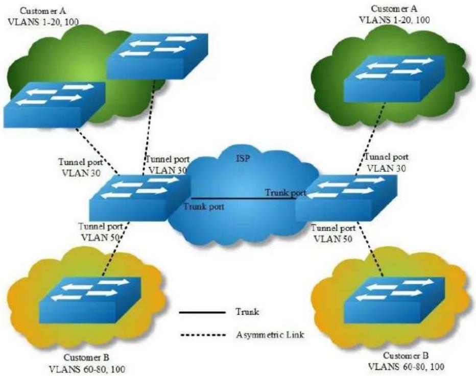
flowchart
graph TD
    subgraph_Customer_A["Customer A VLANS 1-20, 100"]
        A1["Trunk port VLAN 30"] --> A2["Tunnel port VLAN 30"]
        A2 --> A3["ISP"]
        A3 --> A4["Trunk port"]
        A4 --> A5["Customer B VLANS 60-80, 100"]
    end
    subgraph_Customer_B["Customer B VLANS 60-80, 100"]
        B1["Trunk port VLAN 50"] --> B2["Tunnel port VLAN 50"]
        B2 --> B3["ISP"]
        B3 --> B4["Trunk port"]
        B4 --> B5["Customer B VLANS 60-80, 100"]
    end
    A1 -.-> A3
    A2 -.-> A4
    A3 -.-> A5
    A4 -.-> A6
    A5 -.-> A7
    style Customer_A fill:#f9f,stroke:#333
    style Customer_B fill:#f9f,stroke:#333
    style Trunk port fill:#bbf,stroke:#333
    linkStyle 0 stroke:#ff0000,stroke-width:2px
    linkStyle 1 stroke:#ff0000,stroke-width:2px
    linkStyle 2 stroke:#ff0000,stroke-width:2px
    linkStyle 3 stroke:#ff0000,stroke-width:2px
    linkStyle 4 stroke:#ff0000,stroke-width:2px
    linkStyle 5 stroke:#ff0000,stroke-width:2px
    linkStyle 6 stroke:#ff0000,stroke-width:2px
    linkStyle 7 stroke:#ff0000,stroke-width:2px
Figure 3-12 QinQ Tunnel
Using 802.1Q tunneling, the client's VLAN tag is encapsulated in the public VLAN tag and packets with two tags will traverse on backbone network. The client's VLAN tag will be shield and only the public VLAN tag will be used to transmit. By separating data stream, the client's VLAN tag is transmitted transparently and different VLAN tags can be used repeatedly. Therefore, using 802.1Q tunneling expands the available VLAN tags. Two types of 802.1q tunneling are supported: basic 802.1Q tunneling and selective 802.1Q tunneling. Basic 802.1Q tunneling is founded on tagging on ports and all dates will be encapsulated a common VLAN tag of the same port, so this type has great limitations in practical applications. While
selective 802.1Q tunneling can separate data stream and encapsulate different VLAN tags base on different data.
Principle Description
N/A
3.8.2 Configuration
Configuring VLAN Translation
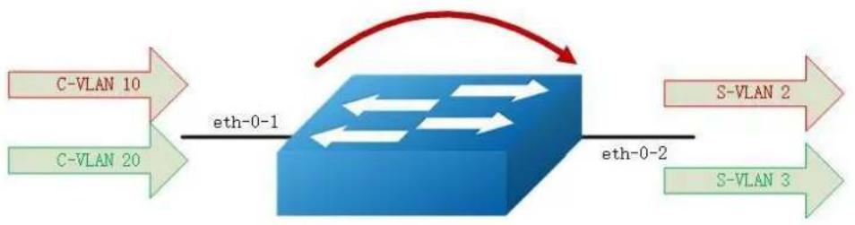
flowchart
graph LR
    A["C-VLAN 10"] -->|eth-0-1| B["Blue Box"]
    C["C-VLAN 20"] -->|eth-0-1| B
    B -->|eth-0-2| D["S-VLAN 2"]
    B -->|eth-0-2| E["S-VLAN 3"]
Figure 3-13 vlan mapping
step 1 Enter the configure mode
Switch# configure terminal
step 2 Enter the vlan configure mode and create vlan
Switch(config)# vlan database
Switch(config-vlan)# vlan 2,3
Switch(config-vlan)# exit
step 3 Create evc and set dot1q mapped vlan
Switch(config)# ethernet evc evc_c1
Switch(config-evc)# dot1q mapped-vlan 2
Switch(config)# ethernet evc evc_c2
Switch(config-evc)# dot1q mapped-vlan 3
step 4 Create vlan mapping table and bind the vlan and evc
Switch(config)# vlan mapping table vm
Switch(config-vlan-mapping)# raw-vlan 10 evc evc_c1
Switch(config-vlan-mapping)# raw-vlan 20 evc evc_c2
Switch(config-vlan-mapping)# exit
step 5 Enable vlan translation on the interface and apply the vlan mapping table
Switch(config)# interface eth-0-1
Switch(config-if)# switchport mode trunk
Switch(config-if)# switchport trunk vlan-translation
Switch(config-if)# switchport trunk vlan-translation mapping table vm
Switch(config-if)# switchport trunk allowed vlan add 2,3
Switch(config-if)# interface eth-0-2
Switch(config-if)# switchport mode trunk
Switch(config-if)# switchport trunk allowed vlan add 2,3
Switch(config-if)# exit
step 6 Exit the configure mode
Switch(config)# end
step 7 Validation
Use the following command to display the information of the switch port interface:
Switch# show interface switchport interface eth-0-1
Interface name : eth-0-1
Switchport mode : trunk
VLAN traslation : enable
VLAN mapping table : vm
Ingress filter : enable
Acceptable frame types : all
Default Vlan : 1
Configured Vlans : 1 2 3
Use the following command to display the information of the vlan mapping table:
Switch# show vlan mapping table
Table Name EVC Name Mapped VLAN Raw VLAN
vm evc_c1 2 10
evc_c2 3 20
Configuring 802.1q Tunneling (Basic 802.1Q tunneling)
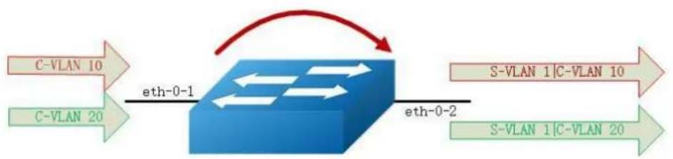
flowchart
graph LR
    A["C-VLAN 10"] --> B["eth-0-1"]
    C["C-VLAN 20"] --> B
    B --> D["eth-0-2"]
    E["S-VLAN 1|C-VLAN 10"] --> D
    F["S-VLAN 1|C-VLAN 20"] --> D
    D --> G["Red arrow indicating transformation"]
Figure 3-14 QinQ Tunnel
step 1 Enter the configure mode
Switch# configure terminal
step 2 Enter the interface configure mode, set the switch port mode
Switch(config)# interface eth-0-1
Switch(config-if)# no shutdown
Switch(config-if)# switchport mode dot1q-tunnel
step 3 Exit the configure mode
Switch(config-if)# end
step 4 Validation
This example shows how to configure a switchport to basic dot1q-tunnel port. You can use show the configuration on the switchport:
Switch# show interface switchport interface eth-0-1
Interface name : eth-0-1
Switchport mode : dotlq-tunnel(basic)
Ingress filter : enable
Acceptable frame types : all
Default Vlan : 1
Configured Vlans : 1
Configuring 802.1q Tunneling (Selective 802.1Q tunneling, Add one tag for incoming untagged packet.)
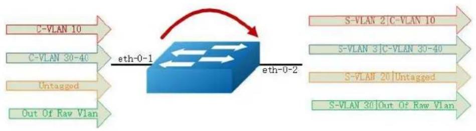
flowchart
graph LR
    A["C-VLAN 10"] -->|eth-0-1| B["Blue Box"]
    C["C-VLAN 30-40"] -->|eth-0-1| B
    D["Untagged"] -->|eth-0-1| B
    E["Out Of Raw Vlan"] -->|eth-0-1| B
    B -->|eth-0-2| F["S-VLAN 2 |C-VLAN 10"]
    B -->|eth-0-2| G["S-VLAN 3 |C-VLAN 30-40"]
    B -->|eth-0-2| H["S-VLAN 20 |Untagged"]
    B -->|eth-0-2| I["S-VLAN 30 |Out Of Raw Vlan"]
Figure 3-15 QinQ Tunnel
step 1 Enter the configure mode
Switch# configure terminal
step 2 Enter the vlan configure mode and create vlan
Switch(config)# vlan database
Switch(config-vlan)# vlan 2,3,20,30
Switch(config-vlan)# exit
step 3 Create evc and set dot1q mapped vlan
Switch(config)# ethernet evc evc_c1
Switch(config-evc)# dot1q mapped-vlan 2
Switch(config)# ethernet evc evc_c2
Switch(config-evc)# dot1q mapped-vlan 3
Switch(config)# ethernet evc evc_c3
Switch(config-evc)# dot1q mapped-vlan 20
Switch(config)# ethernet evc evc_c4
Switch(config-evc)# dot1q mapped-vlan 30
Switch(config-evc)# exit
step 4 Create vlan mapping table and bind the vlan and evc
Switch(config)# vlan mapping table vm
Switch(config-vlan-mapping)# raw-vlan 10 evc evc_c1
Switch(config-vlan-mapping)# raw-vlan 30-40 evc evc_c2
Switch(config-vlan-mapping)# raw-vlan untagged evc evc_c3
Switch(config-vlan-mapping)# raw-vlan out-of-range evc evc_c4
Switch(config-vlan-mapping)# exit
step 5 Enable vlan translation on the interface and apply the vlan mapping table
eth-0-1:
Switch(config-if)# switchport mode dot1q-tunnel
Switch(config-if)# switchport dot1q-tunnel type selective
Switch(config-if)# switchport dot1q-tunnel vlan mapping table vm
Switch(config-if)# switchport dot1q-tunnel allowed vlan add 2,3,20,30
eth-0-2:
Switch(config-if)# switchport mode trunk
Switch(config-if)# switchport trunk allowed vlan add 2,3,20,30
step 6 Exit the configure mode
Switch(config-if)# end
step 7 Validation
This example shows how to configure a switchport to selective dot1q-tunnel port:
Switch# show interface switchport interface eth-0-1
Interface name : eth-0-1
Switchport mode : dot1q-tunnel(selective)
VLAN mapping table : vm
Ingress filter : enable
Acceptable frame types : all
Default Vlan : 1
Configured Vlans : 1 2 3 20 30
Use the following command to display the information of the vlan mapping table:
Switch# show vlan mapping table
Table Name EVC Name Mapped VLAN Raw VLAN
vm evc_c1 2 10
evc_c2 3 30-40
evc_c3 20 untagged
evc_c4 30 out-of-range
Configuring 802.1q Tunneling (Selective 802.1Q tunneling, Add two tags for incoming untagged packet.)
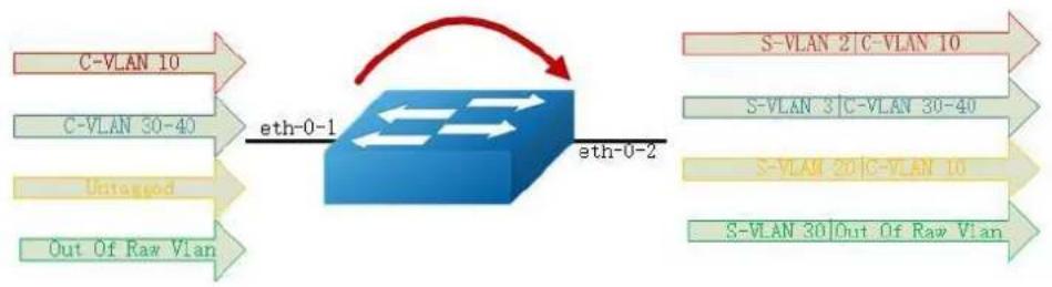
flowchart
graph LR
    A["C-VLAN 10"] -->|eth-0-1| B["Network"]
    C["C-VLAN 30-40"] -->|eth-0-1| B
    D["Untagged"] -->|eth-0-1| B
    E["Out Of Raw Vlan"] -->|eth-0-1| B
    B -->|eth-0-2| F["S-VLAN 2 | C-VLAN 10"]
    B -->|eth-0-2| G["S-VLAN 3 | C-VLAN 30-40"]
    B -->|eth-0-2| H["S-VLAN 20 | C-VLAN 10"]
    B -->|eth-0-2| I["S-VLAN 30 | Out Of Raw Vlan"]
Figure 3-16 QinQ Tunnel
step 1 Enter the configure mode
Switch# configure terminal
step 2 Enter the vlan configure mode and create vlan
Switch(config)# vlan database
Switch(config-vlan)# vlan 2,3,10,20,30
Switch(config-vlan)# exit
step 3 Create evc and set dot1q mapped vlan
Switch(config)# ethernet evc evc_cl
Switch(config-evc)# dotlq mapped-vlan 2
Switch(config-evc)# exit
Switch(config)# ethernet evc evc_c2
Switch(config-evc)# dot1q mapped-vlan 3
Switch(config-evc)# exit
Switch(config)# ethernet evc evc_c3
Switch(config-evc)# dot1q mapped-double-vlan 10 20
Switch(config-evc)# exit
Switch(config)# ethernet evc evc_c4
Switch(config-evc)# dot1q mapped-vlan 30
Switch(config-evc)# exit
step 4 Create vlan mapping table and bind the vlan and evc
Switch(config)# vlan mapping table vm
Switch(config-vlan-mapping)# raw-vlan 10 evc evc_c1
Switch(config-vlan-mapping)# raw-vlan 30-40 evc evc_c2
Switch(config-vlan-mapping)# raw-vlan untagged evc evc_c3
Switch(config-vlan-mapping)# raw-vlan out-of-range evc evc_c4
Switch(config-vlan-mapping)# raw-vlan 10 20 egress-vlan untag
Switch(config-vlan-mapping)# exit
step 5 Enable vlan translation on the interface and apply the vlan mapping table
eth-0-1:
Switch(config)# interface eth-0-1
Switch(config-if)# switchport mode dot1q-tunnel
Switch(config-if)# switchport dot1q-tunnel type selective
Switch(config-if)# switchport dot1q-tunnel vlan mapping table vm
Switch(config-if)# switchport dot1q-tunnel native inner-vlan 10
Switch(config-if)# switchport dot1q-tunnel allowed vlan add 2,3,20,30
Switch(config-if)# exit
eth-0-2:
Switch(config)# interface eth-0-2
Switch(config-if)# switchport mode trunk
Switch(config-if)# switchport trunk allowed vlan add 2,3,20,30
Switch(config-if)# exit
step 6 Exit the configure mode
Switch(config)# end
step 7 Validation
This example shows how to configure a switchport to selective dot1q-tunnel port:
Switch# show interface switchport interface eth-0-1
Interface name : eth-0-1
Switchport mode : dot1q-tunnel(selective)
VLAN mapping table : vm
Ingress filter : enable
Acceptable frame types : all
Default Vlan : 10
Configured Vlans : 1 2 3 20 30
Use the following command to display the information of the vlan mapping table:
Table Name EVC Name Mapped VLAN Raw VLAN
vm evc_c1 2 10
evc_c2 3 30-40
evc_c3 20(10) untagged
evc_c4 30 out-of-range
3.8.3 Application cases
N/A
3.9 Configuring Link Aggregation
3.9.1 Overview
Function Introduction
This chapter contains a sample configuration of Link Aggregation Control Protocol (LACP). LACP is based on the 802.3ad IEEE specification. It allows bundling of several physical interfaces to form a single logical channel providing enhanced performance and redundancy. The aggregated interface is viewed as a single link to each switch. The spanning tree views it as one interface. When there is a failure in one physical interface, the other interfaces stay up and there is no disruption. This implementation supports the aggregation of maximum 16 physical Ethernet links into a single logical channel. LACP enables our device to manage link aggregation group between other devices that conform to the 802.3ad protocol. By using the LACP, the switch learns the identity of partners supporting LACP and the capabilities of each port. It then dynamically groups ports with same properties into a single logical bundle link.
Reference to standard IEEE 802.3ad.
Principle Description
N/A
3.9.2 Configuration
Configure dynamic lacp
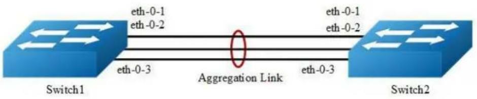
flowchart
graph LR
    Switch1["Switch1"] -->|eth-0-1\neth-0-2| AggregationLink["Aggregation Link"]
    Switch1 -->|eth-0-3\neth-0-2| AggregationLink
    AggregationLink -->|eth-0-3\neth-0-1| Switch2["Switch2"]
Figure 3-17 Dynamic LACP
The configurations of Switch1 and Switch2 are as below:
step 1 Enter the configure mode
Switch# configure terminal
step 2 Set the global attributes of LACP
Set the dynamic lacp mode of aggregation groups.
Switch1 configuration:
Switch(config)# port-channel 1 lacp-mode dynamic
Switch2 configuration:
Switch(config)# port-channel 1 lacp-mode dynamic
step 3 Enter the interface configure mode and add the interface to the channel group
Switch(config)# interface eth-0-1
Switch(config-if)# no shutdown
Switch(config-if)# channel-group 1 mode active
Switch(config-if)# exit
Switch(config)# interface eth-0-2
Switch(config-if)# channel-group 1 mode active
Switch(config-if)# no shutdown
Switch(config-if)# exit
Switch(config)# interface eth-0-3
Switch(config-if)# channel-group 1 mode active
Switch(config-if)# no shutdown
Switch(config-if)# exit
step 4 Exit the configure mode
Switch(config)# end
step 5 Validation
Use the following command to display the information of the channel-group:
Switch# show channel-group summary
port-channel load-balance hash-arithmetic: xor
port-channel load-balance hash-field-select:
macsa
Flags: s - suspend T - standby
D - down/admin down B - in Bundle
R - Layer3 S - Layer2
w - wait U - in use
Mode: SLB - static load balance
DLB - dynamic load balance
SHLB - self-healing load balance
RR - round robin load balance
Aggregator Name Mode Protocol Ports
aggl(SU) SLB LACP(Dynamic) eth-0-1(B) eth-0-2(B) eth-0-3(B)
Use the following command to display the information of the interface agg:
Switch1# show interface agg1
Interface agg1
Interface current state: UP
Hardware is AGGREGATE, address is cce3.33fc.330b (bia cce3.33fc.330b)
Bandwidth 3000000 kbits
Index 1025 , Metric 1 , Encapsulation ARPA
Speed - 1000Mb/s , Duplex - Full , Media type is Aggregation
Link speed type is autonegotiation, Link duplex type is autonegotiation
Input flow-control is off, output flow-control is off
The Maximum Frame Size is 1534 bytes
VRF binding: not bound
Label switching is disabled
No virtual circuit configured
ARP timeout 01:00:00, ARP retry interval ls
5 minute input rate 0 bits/sec, 0 packets/sec
5 minute output rate 2 bits/sec, 0 packets/sec
13 packets input, 1184 bytes
Received 0 unicast, 0 broadcast, 0 multicast
0 runts, 0 giants, 0 input errors, 0 CRC
0 frame, 0 overrun, 0 pause input
0 input packets with dribble condition detected
20 packets output, 2526 bytes
Transmitted 0 unicast, 0 broadcast, 0 multicast
0 underruns, 0 output errors, 0 pause output
Configure channel-group
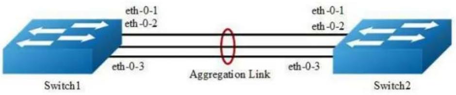
flowchart
graph LR
    Switch1["Switch1"] -->|eth-0-1\neth-0-2| AggregationLink["Aggregation Link"]
    Switch1 -->|eth-0-3| AggregationLink
    Switch2["Switch2"] -->|eth-0-1\neth-0-2| AggregationLink
    Switch2 -->|eth-0-3| AggregationLink
Figure 3-18 Static LACP
The configurations of Switch1 and Switch2 are as below:
step 1 Enter the configure mode
Switch# configure terminal
step 2 Set the global attributes of LACP
Set the system priority of this switch. This priority is used for determining the system that is responsible for resolving conflicts in the choice of aggregation groups. A lower numerical value has a higher priority. Set the load balance mode. In this case we choose source MAC address for load balance.
Switch1 configuration:
Switch(config)# lacp system-priority 2000
Switch(config)# hash-field port-channel
Switch(config-hash-field)# 12 macsa
Switch2 configuration:
Switch(config)# lacp system-priority 1000
Switch(config)# hash-field port-channel
Switch(config-hash-field)# 12 macsa
step 3 Enter the interface configure mode and add the interface to the channel group
Switch(config)# interface eth-0-1
Switch(config-if)# no shutdown
Switch(config-if)# channel-group 1 mode active
Switch(config-if)# exit
Switch(config)# interface eth-0-2
Switch(config-if)# channel-group 1 mode active
Switch(config-if)# no shutdown
Switch(config-if)# exit
Switch(config)# interface eth-0-3
Switch(config-if)# channel-group 1 mode active
Switch(config-if)# no shutdown
Switch(config-if)# exit
step 4 Exit the configure mode
Switch(config)# end
step 5 Validation
Use the following command to display the information of the channel-group:
Switch# show channel-group summary
port-channel load-balance hash-arithmetic: xor
port-channel load-balance hash-field-select:
macsa
Flags: s - suspend T - standby
D - down/admin down B - in Bundle
R - Layer3 S - Layer2
w - wait U - in use
Mode: SLB - static load balance
DLB - dynamic load balance
SHLB - self-healing load balance
RR - round robin load balance
Aggregator Name Mode Protocol Ports
aggl(SU) SLB LACP eth-0-1(B) eth-0-2(B) eth-0-3(B)
Use the following command to display the information of the interface agg:
Switch1# show interface agg1
Interface agg1
Interface current state: UP
Hardware is AGGREGATE, address is cce3.33fc.330b (bia cce3.33fc.330b)
Bandwidth 3000000 kbits
Index 1025 , Metric 1 , Encapsulation ARPA
Speed - 1000Mb/s , Duplex - Full , Media type is Aggregation
Link speed type is autonegotiation, Link duplex type is autonegotiation
Input flow-control is off, output flow-control is off
The Maximum Frame Size is 1534 bytes
VRF binding: not bound
Label switching is disabled
No virtual circuit configured
ARP timeout 01:00:00, ARP retry interval ls
5 minute input rate 0 bits/sec, 0 packets/sec
5 minute output rate 2 bits/sec, 0 packets/sec
13 packets input, 1184 bytes
Received 0 unicast, 0 broadcast, 0 multicast
0 runts, 0 giants, 0 input errors, 0 CRC
0 frame, 0 overrun, 0 pause input
0 input packets with dribble condition detected
20 packets output, 2526 bytes
Transmitted 0 unicast, 0 broadcast, 0 multicast
0 underruns, 0 output errors, 0 pause output
Configuring Static-channel-group
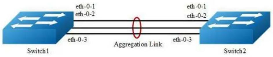
flowchart
graph LR
    Switch1["Switch1"] -->|eth-0-1\neth-0-2| AggregationLink["Aggregation Link"]
    Switch1 -->|eth-0-3\neth-0-2| AggregationLink
    Switch2["Switch2"] -->|eth-0-1\neth-0-2| AggregationLink
    Switch2 -->|eth-0-3\neth-0-3| AggregationLink
Figure 3-19 Static Agg
The configurations of Switch1 and Switch2 are as below:
step 1 Enter the configure mode
Switch# configure terminal
step 2 Enter the interface configure mode and add the interface to the channel group
Switch(config)# interface eth-0-1
Switch(config-if)# no shutdown
Switch(config-if)# static-channel-group 1
Switch(config-if)# exit
Switch(config)# interface eth-0-2
Switch(config-if)# static-channel-group 1
Switch(config-if)# no shutdown
Switch(config-if)# exit
Switch(config)# interface eth-0-3
Switch(config-if)# static-channel-group 1
Switch(config-if)# no shutdown
Switch(config-if)# exit
step 3 Exit the configure mode
Switch(config)# end
step 4 Validation
Use the following command to display the information of the channel-group:
Switch1# show channel-group summary
port-channel load-balance hash-arithmetic: xor
port-channel load-balance hash-field-select:
macsa
Flags: s - suspend T - standby
D - down/admin down B - in Bundle
R - Layer3 S - Layer2
w - wait U - in use
Mode: SLB - static load balance
DLB - dynamic load balance
SHLB - self-healing load balance
RR - round robin load balance
Aggregator Name Mode Protocol Ports
aggl(SU) SLB Static eth-0-1(B) eth-0-2(B) eth-0-3(B)
Use the following command to display the information of the interface agg:
Switch1# show interface agg 1
Interface agg1
Interface current state: UP
Hardware is AGGREGATE, address is cce3.33fc.330b (bia a876.6b2c.9c01)
Bandwidth 3000000 kbits
Index 1025, Metric 1, Encapsulation ARPA
Speed - 1000Mb/s, Duplex - Full, Media type is Aggregation
Link speed type is autonegotiation, Link duplex type is autonegotiation
Input flow-control is off, output flow-control is off
The Maximum Frame Size is 1534 bytes
VRF binding: not bound
Label switching is disabled
No virtual circuit configured
ARP timeout 01:00:00, ARP retry interval ls
5 minute input rate 0 bits/sec, 0 packets/sec
5 minute output rate 140 bits/sec, 0 packets/sec
0 packets input, 0 bytes
Received 0 unicast, 0 broadcast, 0 multicast
0 runts, 0 giants, 0 input errors, 0 CRC
0 frame, 0 overrun, 0 pause input
0 input packets with dribble condition detected
1080 packets output, 60614 bytes
Transmitted 0 unicast, 0 broadcast, 0 multicast
0 underruns, 0 output errors, 0 pause output
3.9.3 Application cases
N/A
3.10 Configuring Flow Control
3.10.1 Overview
Function Introduction
Flow control enables connected Ethernet ports to control traffic rates during congestion by allowing congested nodes to pause link operation at the other end. If one port experiences congestion and cannot receive any more traffic, it notifies the other port to stop sending until the condition clears. When the local device detects any congestion at its end, it can notify the link partner or the remote device of the congestion by sending a pause frame. You can use the flowcontrol interface configuration command to set the interface's ability to receive and send pause frames to on, off. The default state for ports is receive off and send off. In auto-negotiation link, local device's flow control ability can be notified to link partner by link up/down.

NOTE
Flow control send/receive on ability only works on full duplex link
Principle Description
N/A
3.10.2 Configuration
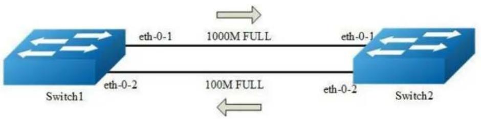
flowchart
graph LR
    A["Switch1"] -->|eth-0-1| B["1000M FULL"]
    B -->|eth-0-1| C["Switch2"]
    A -->|eth-0-2| D["100M FULL"]
    D -->|eth-0-2| C
Figure 3-20 Flow control
Configuring Flow Control Send
step 1 Enter the configure mode
Switch# configure terminal
step 2 Enter the interface configure mode and enable flowcontrol send
Switch(config)# interface eth-0-1
Switch(config-if)# flowcontrol send on
step 3 Exit the configure mode
Switch(config-if)# end
step 4 Validation
Use the following command to display the information of flow control:
Switch# show flowcontrol
Port Receive FlowControl Send FlowControl RxPause TxPause
admin oper admin oper
eth-0-1 off off on on 0 0
eth-0-2 off off off off 0 0
eth-0-3 off off off off 0 0
Use the following command to display the information of flow control on specified interface:
Switch# show flowcontrol eth-0-1
Port Receive FlowControl Send FlowControl RxPause TxPause
admin oper admin oper
eth-0-1 off off on on 0 0
Configuring Flow Control Receive
step 1 Enter the configure mode
Switch# configure terminal
step 2 Enter the interface configure mode and enable flowcontrol send
Switch(config)# interface eth-0-1
Switch1(config-if)# flowcontrol receive on
step 3 Exit the configure mode
Switch(config-if)# end
step 4 Validation
Use the following command to display the information of flow control:
Switch1# show flowcontrol
Port Receive FlowControl Send FlowControl RxPause TxPause
admin oper admin oper
eth-0-1 on on off off 0 0
eth-0-2 off off off off 0 0
eth-0-3 off off off off 0 0
Use the following command to display the information of flow control on specified interface:
Switch1# show flowcontrol eth-0-1
Port Receive FlowControl Send FlowControl RxPause TxPause
admin oper admin oper
eth-0-1 on on off off 0 0
3.10.3 Application cases
N/A
3.11 Configuring Storm Control
3.11.1 Overview
Function Introduction
Storm control prevents traffic on a LAN from being disrupted by a broadcast, a multicast, or a unicast storm on one of the physical interfaces. A LAN storm occurs when packets flood the LAN, creating excessive traffic and degrading network performance.
Storm control uses one of these methods to measure traffic activity:
Bandwidth as a percentage of the total available bandwidth of the port (Level mode).
➢ Traffic rate in packets per second of the port (PPS mode).
PPS = Packets per second
Principle Description
N/A
3.11.2 Configuration
Configuring Bandwidth Percentage Storm Control
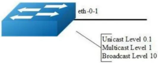
flowchart
graph TD
    A["eth-0-1"] --> B["Unicast Level 0.1"]
    A --> C["Multicast Level 1"]
    A --> D["Broadcast Level 10"]
Figure 3-21 Percentage Storm Control
step 1 Enter the configure mode
Switch# configure terminal
step 2 Enter the interface configure mode, and set the storm control level
User can set different level for Unknown unicast/multicast/broad cast packets:
Switch(config)# interface eth-0-1
Switch(config-if)# storm-control unicast level 0.1
Switch(config-if)# storm-control multicast level 1
Switch(config-if)# storm-control broadcast level 10
step 3 Exit the configure mode
Switch(config-if)# end
step 4 Validation
Switch# show storm-control interface eth-0-1
Port ucastMode ucastlevel bcastMode bcastLevel mcastMode mcastLevel
eth-0-1 Level 0.10 Level 10.00 Level 1.00
Configuring Packets per-Second Storm Control
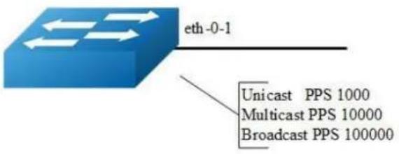
flowchart
graph TD
    A["eth-0-1"] --> B["Unicast PPS 1000"]
    A --> C["Multicast PPS 10000"]
    A --> D["Broadcast PPS 100000"]
Figure 3-22 PPS Storm Control
step 1 Enter the configure mode
Switch# configure terminal
step 2 Enter the interface configure mode, and set the storm control pps
User can set different pps for Unknown unicast/multicast/broad cast packets:
Switch(config)# interface eth-0-1
Switch(config-if)# storm-control unicast pps 1000
Switch(config-if)# storm-control multicast pps 10000
Switch(config-if)# storm-control broadcast pps 100000
step 3 Exit the configure mode
Switch(config-if)# end
step 4 Validation
Switch# show storm-control interface eth-0-1
Port ucastMode ucastlevel bcastMode bcastLevel mcastMode mcastLevel
eth-0-1 PPS 1000 PPS 100000 PPS 10000
3.11.3 Application cases
N/A
3.12 Configuring Loopback Detection
3.12.1 Overview
Function Introduction
The loopback in the networks would cause the device continued to send broadcast, multicast and unknown unicast packets. It will waste the resource of network even paralysis the whole network. To detect the loopback in the layer 2 network rapidly and avoid to effect the whole network, system need to provide a detection function to notice the user checking the network connection and configuration, and control the error interface when the network appears loopback.
Loopback Detection can detect whether the interface of device exists loopback. When enable loopback detection on a interface, device will send detection packets from this interface by periodically. If the device receives detection packets sent from the interface, this interface is considered that there is a loop existed and the device can send alarm information to network management system. Administrators discover loopback problem through alarm information and resolve the problem to avoid longtime network abnormal. In addition, the device can control the specific interface and configured Trap according the requirement, and disable the interface to quickly reduce the impact in the network of loopback to the minimum.
Principle Description
N/A
3.12.2 Configuration
Enable Loopback Detect
step 1 Enter the configure mode
Switch# configure terminal
step 2 Enter the interface configure mode, and enable Loopback Detect
Switch(config)# interface eth-0-1
Switch(config-if)# loopback-detect enable
step 3 Exit the configure mode
Switch(config-if)# end
step 4 Validation
By default, loopback detection is disable. When the interface enable loopback detection, system send the detection packets to detect the loopback. Default detection packets transmission interval is 5 second.
Use the following command to display the loopback detection states:
Switch# show loopback-detect
Loopback detection packet interval (second): 5
Loopback detection recovery time (second): 15
Interface Action Status
eth-0-2 shutdown NORMAL
Configuring Loopback Detect packet interval
The network is changing all the time, therefore the loopback detection is an continued process. The interface sent loopback detection packets in a certain interval of time, the packets transmission time is loopback detection packets sending period.
The device send the lopback detection packets time interval range is 1 to 300 seconds. The loopback status recover period default is 3 times of the interface send interval.
step 1 Enter the configure mode
Switch# configure terminal
step 2 set the packet interval of Loopback Detect
Switch(config)# loopback-detect packet-interval 10
step 3 Exit the configure mode
Switch(config)# end
step 4 Validation
Use the following command to display the packet interval of Loopback Detect:
Switch# show loopback-detect packet-interval
Loopback detection packet interval(second): 10
Configuring Loopback Detect action
If a loopback is detected on the interface and loopback is enabled on this interface, the system can configure an action to send alarm, shutdown the interface, block the interface or other action.
After loopback detection is enabled on an interface, the interface sends loopback detection packets at intervals. When a loopback is detected on the interface, the system performs an action to minimize the impact on the entire network.
step 1 Enter the configure mode
Switch# configure terminal
step 2 Enter the interface configure mode, and set the action of Loopback Detect
Switch(config)# interface eth-0-1
Switch(config-if)# loopback-detect action shutdown
step 3 Exit the configure mode
Switch(config)# end
step 4 Validation
Use the following command to display the information of Loopback Detect on the interface:
Switch# show loopback-detect interface eth-0-1
Interface Action Status
eth-0-1 shutdown NORMAL
Configuring specify VLAN Loopback Detection
specify the VLAN IDs of loopback detection packets on an interface After loopback detection is enabled on an interface, system send untagged loopback detection
packets by default. It means the device dosen't detect any specify vlan loopback packets. When interface is configured Tagged mode in vlan, the loopback detection packets sent by this interface will be discard on the link, and interface won't receive the loop packets which is sent by itself. So we should specify the VLAN IDs of loopback detection packets on an interface.
After the loopback-detect packet vlan command is executed on an interface, the interface sends an untagged loopback detection packet and the loopback detection packets with the specified VLAN tags. The specified VLANs exist and the interface has been added to the VLANs in tagged mode. If you run the loopback-detect packet vlan command multiple times in the same interface view, multiple VLAN IDs are specified. You can specify a maximum of eight VLAN IDs
step 1 Enter the configure mode
Switch# configure terminal
step 2 Enter the interface configure mode, and set the specify vlan of Loopback Detect
Switch(config)# interface eth-0-1
Switch(config-if)# loopback-detect packet vlan 20
step 3 Exit the configure mode
Switch(config-if)# end
step 4 Validation
Use the following command to display the configuration of Loopback Detect:
Switch# show running-config interface eth-0-1
Building configuration...
!
interface eth-0-1
loopback-detect enable
loopback-detect packet vlan 20
!
3.12.3 Application cases
N/A
3.13 Configuring Layer 2 Protocols Tunneling
3.13.1 Overview
Function Introduction
Customers at different sites connected across a service-provider network need to run various Layer 2 protocols to scale their topology to include all remote sites, as well as the local sites. STP must run properly, and every VLAN should build a proper spanning tree that includes the local site and all remote sites across the service-provider infrastructure.
When Layer 2 protocol tunneling is enabled, edge switches on the inbound side of the service-provider infrastructure encapsulate Layer 2 protocol packets with a new Layer 2 header and send them across the service-provider network. Core switches in the network do not process these packets but forward them as normal packets. Layer 2 protocol packets pass the service-provider infrastructure and reach customer switches on the outbound side of the service-provider network. The new Layer 2 header will be stripped when the Layer 2 protocol packets are sent to customer switches. Layer 2 protocol tunneling can be used independently or can enhance 802.1Q tunneling.
Principle Description
N/A
3.13.2 Configuration
Tunnel Designed Layer2 Protocol Packets
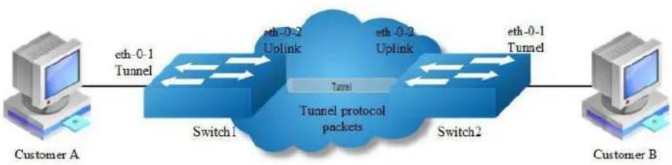
flowchart
graph LR
    A["Customer A"] -->|eth-0-1 Tunnel| B["Switch1"]
    B -->|eth-0-2 Uplink| C["Tunnel protocol packets"]
    C -->|eth-0-2 Uplink| D["Switch2"]
    D -->|eth-0-1 Tunnel| E["Customer B"]
Figure 3-23 L2 protocol tunnel
The designed Layer2 protocol packets include STP BPDU, LACP slow proto, DOT1X EAPOL, CFM.
In this example, one link is between Switch1 and Switch2. Switch1 eth-0-1 and Switch2 eth-0-1 are configured tunnel port. Switch1 eth-0-2 and Switch2 eth-0-2 are configured uplink port. If protocol packets are received on port eth-0-1 of Switch1, packets should be added new Layer 2 header and sent out from uplink port. The new Layer 2 header will be as follows: MAC da should be tunnel dmac; MAC sa should be switch route-mac; VLAN ID should be tunnel vid; VLAN priority (cos) should be Layer 2 Protocol cos; Ethertype should be 0xFFEE. When the packets with new Layer 2 header are received on port eth-0-2 of Switch2, new Layer 2 header will be stripped and the packets will be sent to port eth-0-1 of Switch2.
step 1 Enter the configure mode
Switch# configure terminal
step 2 Enter the vlan configure mode and create vlan
Switch(config)# vlan database
Switch(config-vlan)# vlan 2-4
Switch(config-vlan)# exit
step 3 Create evc and set dot1q mapped vlan
Switch(config)# ethernet evc evc_c1
Switch(config-evc)# dot1q mapped-vlan 2
Switch(config-evc)# exit

Switch(config)# ethernet evc evc_c2
Switch(config-evc)# dot1q mapped-vlan 3
Switch(config-evc)# exit

Switch(config)# ethernet evc evc_c3
Switch(config-evc)# dot1q mapped-vlan 4
Switch(config-evc)# exit
step 4 Enable l2 protocol, set the tunnel destination mac and add l2 protocao mac address
Switch(config)# 12protocol enable
Switch(config)# 12protocol tunnel-dmac 0100.0CCD.CDD2
Switch(config)# 12protocol mac 3 0180.C200.0008
Switch(config)# 12protocol mac 4 0180.C200.0009
Switch(config)# 12protocol full-mac 0100.0CCC.CCCC
step 5 Enter the interface configure mode and set the attributes of the interfaces. Bind the l2 protocol mac and the evc
Switch(config)# interface eth-0-1
Switch(config-if)# no shutdown
Switch(config-if)# switchport mode trunk
Switch(config-if)# switchport trunk allowed vlan add 2-4
Switch(config-if)# spanning-tree port disable
Switch(config-if)# 12protocol mac 3 tunnel evc evc_c1
Switch(config-if)# 12protocol mac 4 tunnel evc evc_c2
Switch(config-if)# 12protocol full-mac tunnel evc evc_c3
Switch(config)# interface eth-0-2
Switch(config-if)# no shutdown
Switch(config-if)# switchport mode trunk
Switch(config-if)# switchport trunk allowed vlan add 2-4
Switch(config-if)# 12protocol uplink enable
step 6 Exit the configure mode
Switch(config-if)# end
step 7 Validation
Use the following command to display the information of tunnel interface:
Switch1# show l2protocol interface eth-0-1
Interface PDU Address MASK Status EVC
---- ---- ---- ---- ---- ----
eth-0-1 0180.c200.0008 FFFF.FFFF.FFFF Tunnel evc_c1
eth-0-1 0180.c200.0009 FFFF.FFFF.FFFF Tunnel evc_c2
eth-0-1 0100.0ccc.cccc FFFF.FFFF.FFFF Tunnel evc_c3
eth-0-1 stp FFFF.FFFF.FFFF Peer N/A
eth-0-1 slow-proto FFFF.FFFF.FFFF Peer N/A
eth-0-1 dotlx FFFF.FFFF.FFFF Peer N/A
eth-0-1 cfm FFFF.FFFF.FFFF Peer N/A
Use the following command to display the information of uplink interface:
Switch1# show 12protocol interface eth-0-2
Interface PDU Address MASK Status EVC
---- ---- ---- ---- ---- ----
eth-0-2 0180.c200.0008 FFFF.FFFF.FFFF Peer N/A
eth-0-2 0180.c200.0009 FFFF.FFFF.FFFF Peer N/A
eth-0-2 0100.0ccc.cccc FFFF.FFFF.FFFF Peer N/A
eth-0-2 stp FFFF.FFFF.FFFF Peer N/A
eth-0-2 slow-proto FFFF.FFFF.FFFF Peer N/A
eth-0-2 dotlx FFFF.FFFF.FFFF Peer N/A
eth-0-2 cfm FFFF.FFFF.FFFF Peer N/A
eth-0-2 N/A N/A Uplink N/A
Use the following command to display the information of tunnel destination mac:
Switch1# show 12protocol tunnel-dmac Layer2 protocols tunnel destination MAC address is 0100.0ccd.cdd2
3.13.3 Application cases
N/A
3.14 Configuring MSTP
3.14.1 Overview
Function Introduction
The MSTP (Multiple Spanning Tree Algorithm and Protocol (IEEE 802.1Q-2005)) enables multiple VLANs to be mapped to the same spanning-tree instance, thereby reducing the number of spanning-tree instances needed to support a large number of VLANs. The MSTP provides for multiple forwarding paths for data traffic and enables load balancing. It improves the fault tolerance of the network because a failure in one instance (forwarding path) does not affect other instances (forwarding paths). The most common initial deployment of MSTP is in the backbone and distribution layers of a Layer 2 switched network; this deployment provides the highly-available network required in a service-provider environment. When the switch is in the multiple spanning-tree (MST) modes, the Rapid Spanning Tree Protocol (RSTP), which is based on IEEE 802.1w, is automatically enabled. The RSTP provides rapid convergence of the spanning tree through explicit handshaking that eliminates the IEEE 802.1D forwarding delay and quickly transitions root ports and designated ports to the forwarding state.
Principle Description
N/A
3.14.2 Configuration
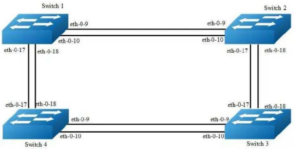
flowchart
graph TD
    A["Switch 1"] -->|eth-0-9| B["Switch 2"]
    A -->|eth-0-10| C["Switch 3"]
    A -->|eth-0-17| D["Switch 4"]
    B -->|eth-0-17| E["Switch 3"]
    B -->|eth-0-18| F["Switch 4"]
    C -->|eth-0-9| G["Switch 4"]
    C -->|eth-0-10| H["Switch 4"]
    D -->|eth-0-17| I["Switch 3"]
    D -->|eth-0-18| J["Switch 4"]
Figure 3-24 MSTP
The configurations of Switch1-Switch4 are as blow. The configurations of these 4 Switches are same if there is no special description.
step 1 Enter the configure mode
Switch# configure terminal
step 2 Set the mode of STP
Switch(config)# spanning-tree mode mstp
step 3 Enter the vlan configure mode and create vlan
Switch(config)# vlan database
Switch(config-vlan)# vlan 10
Switch(config-vlan)# vlan 20
Switch(config-vlan)# exit
step 4 Enter the MSTP configure mode, create region and instance. Bind the vlan to the instance.
Switch(config)# spanning-tree mst configuration
Switch(config-mst)# region RegionName
Switch(config-mst)# instance 1 vlan 10
Switch(config-mst)# instance 2 vlan 20
Switch(config-mst)# exit
step 5 Enter the interface configure mode, set the attributes of the interfaces
Switch(config)# interface eth-0-9
Switch(config-if)# switchport mode trunk
Switch(config-if)# switchport trunk allowed vlan all
Switch(config-if)# no shutdown
Switch(config-if)# exit

Switch(config)# interface eth-0-10
Switch(config-if)# switchport mode trunk
Switch(config-if)# switchport trunk allowed vlan all
Switch(config-if)# no shutdown
Switch(config-if)# exit

Switch(config)# interface eth-0-17
Switch(config-if)# switchport mode trunk
Switch(config-if)# switchport trunk allowed vlan all
Switch(config-if)# no shutdown
Switch(config-if)# exit

Switch(config)# interface eth-0-18
Switch(config-if)# switchport mode trunk
Switch(config-if)# switchport trunk allowed vlan all
Switch(config-if)# no shutdown
Switch(config-if)# exit
step 6 Enable STP and set priority for each swicth
Switch1:
Switch# configure terminal
Switch(config)# spanning-tree priority 0
Switch(config)# spanning-tree enable
Switch2:
Switch# configure terminal
Switch(config)# spanning-tree instance 1 priority 0
Switch(config)# spanning-tree enable
Switch3:
Switch# configure terminal
Switch(config)# spanning-tree instance 2 priority 0
Switch(config)# spanning-tree enable
Switch4:
Switch# configure terminal
Switch(config)# spanning-tree enable
step 7 Exit the configure mode
Switch(config)# end
step 8 Validation
Use the following command to display the information of MSTP on Switch1:
Switch# show spanning-tree mst brief
<h5 id="mst0-vlans-1">MST0: Vlans: 1</h5>
Multiple spanning tree protocol Enabled
Root ID Priority 0 (0x0000)
Address 2225.fa28.c900
Hello Time 2 sec Max Age 20 sec Forward Delay 15 sec
Bridge ID Priority 0 (0x0000)
Address 2225.fa28.c900
Hello Time 2 sec Max Age 20 sec Forward Delay 15 sec
Aging Time 300 sec
Interface Role State Cost Priority.Number Type
eth-0-9 Designated Forwarding 20000 128.9 P2p
eth-0-10 Designated Forwarding 20000 128.10 P2p
eth-0-17 Designated Forwarding 20000 128.17 P2p
eth-0-18 Designated Forwarding 20000 128.18 P2p
<h5 id="mst1-vlans-10">MST1: Vlans: 10</h5>
Root ID Priority 1 (0x0001)
Address 9c9a.7d91.9f00
Bridge ID Priority 32769 (0x8001)
Address 2225.fa28.c900
Interface Role State Cost Priority.Number Type
eth-0-9 Rootport Forwarding 20000 128.9 P2p
eth-0-10 Alternate Discarding 20000 128.10 P2p
eth-0-17 Designated Forwarding 20000 128.17 P2p
eth-0-18 Designated Forwarding 20000 128.18 P2p
<h5 id="mst2-vlans-20">MST2: Vlans: 20</h5>
Root ID Priority 2 (0x0002)
Address 304c.275b.b200
Bridge ID Priority 32770 (0x8002)
Address 2225.fa28.c900
Interface Role State Cost Priority.Number Type
eth-0-9 Alternate Discarding 20000 128.9 P2p
eth-0-10 Alternate Discarding 20000 128.10 P2p
eth-0-17 Rootport Forwarding 20000 128.17 P2p
eth-0-18 Alternate Discarding 20000 128.18 P2p
Use the following command to display the information of MSTP on Switch2:
Switch# show spanning-tree mst brief
<h6 id="mst0-vlans-1-2">MST0: Vlans: 1</h6>
Multiple spanning tree protocol Enabled
Root ID Priority 0 (0x0000)
Address 2225.fa28.c900
| Bridge ID | Hello Time | 2 sec Max Age | 20 sec Forward Delay 15 sec | ||
| Priority | 32768 (0x8000) | ||||
| Address | 9c9a.7d91.9f00 | ||||
| Hello Time | 2 sec Max Age | 20 sec Forward Delay 15 sec | |||
| Aging Time | 300 sec | ||||
| Interface | Role | State | Cost | Priority.Number | Type |
| eth-0-9 | Rootport | Forwarding | 20000 | 128.9 | P2p |
| eth-0-10 | Alternate | Discarding | 20000 | 128.10 | P2p |
| eth-0-17 | Designated | Forwarding | 20000 | 128.17 | P2p |
| eth-0-18 | Designated | Forwarding | 20000 | 128.18 | P2p |
| ##### MST1: | Vlans: 10 | ||||
| Root ID | Priority | 1 (0x0001) | |||
| Address | 9c9a.7d91.9f00 | ||||
| Bridge ID | Priority | 1 (0x0001) | |||
| Address | 9c9a.7d91.9f00 | ||||
| Interface | Role | State | Cost | Priority.Number | Type |
| eth-0-9 | Designated | Forwarding | 20000 | 128.9 | P2p |
| eth-0-10 | Designated | Forwarding | 20000 | 128.10 | P2p |
| eth-0-17 | Designated | Forwarding | 20000 | 128.17 | P2p |
| eth-0-18 | Designated | Forwarding | 20000 | 128.18 | P2p |
| ##### MST2: | Vlans: 20 | ||||
| Root ID | Priority | 2 (0x0002) | |||
| Address | 304c.275b.b200 | ||||
| Bridge ID | Priority | 32770 (0x8002) | |||
| Address | 9c9a.7d91.9f00 | ||||
| Interface | Role | State | Cost | Priority.Number | Type |
| eth-0-9 | Designated | Forwarding | 20000 | 128.9 | P2p |
| eth-0-10 | Designated | Forwarding | 20000 | 128.1o | P2p |
| eth-0-17 | Rootport | Forwarding | 20000 | 128.17 | P2p |
| eth-0-18 | Alternate | Discarding | 20000 | 128.18 | P2p |
Use the following command to display the information of MSTP on Switch3:
| Switch# show spanning-tree mst brief | ||||
| ##### MST0: Vlans: 1 | ||||
| Multiple spanning tree protocol Enabled | ||||
| Root ID Priority 0 (0x0000) | ||||
| Address 2225.fa28.c900 | ||||
| Hello Time 2 sec Max Age 20 sec Forward Delay 15 sec | ||||
| Bridge ID Priority 32768 (0x8000) | ||||
| Address 304c.275b.b200 | ||||
| Hello Time 2 sec Max Age 20 sec Forward Delay 15 sec | ||||
| Aging Time 300 sec | ||||
| Interface Role State | Cost | Priority.Number | Type | |
| cth-0-9 Rootport Forwarding | 20000 | 128.9 | P2p | |
| eth-0-10 Alternate Discarding | 20000 | 128.10 | P2p | |
| eth-0-17 Alternate Discarding | 20000 | 128.17 | P2p | |
| cth-0-18 Alternate Discarding | 20000 | 128.18 | P2p | |
| ##### MST1: Vlans: 10 | ||||
| Root ID Priority 1 (0x0001) | ||||
| Address 9c9a.7d91.9f00 | ||||
| Bridge ID Priority 32769 (0x8001) | ||||
| Interface | Address Role | 304c.275b.b200 State | Cost | Priority.Number | Type |
| eth-0-9 | Designated | Forwarding | 20000 | 128.9 | P2p |
| eth-0-10 | Designated | Forwarding | 20000 | 128.10 | P2p |
| eth-0-17 | Rootport | Forwarding | 20000 | 128.17 | P2p |
| eth-0-18 | Alternate | Discarding | 20000 | 128.18 | P2p |
| ##### MST2: | Vlans: 20 | ||||
| Root ID | Priority Address | 2 (0x0002)304c.275b.b200 | |||
| Bridge ID | Priority Address | 2 (0x0002)304c.275b.b200 | |||
| Interface | Role | State | Cost | Priority.Number | Type |
| eth-0-9 | Designated | Forwarding | 20000 | 128.9 | P2p |
| eth-0-10 | Designated | Forwarding | 20000 | 128.10 | P2p |
| eth-0-17 | Designated | Forwarding | 20000 | 128.17 | P2p |
| eth-0-18 | Designated | Forwarding | 20000 | 128.18 | P2p |
Use the following command to display the information of MSTP on Switch4:
Switch# show spanning-tree mst brief
| Switch# show spanning-tree mst brief | |||||
| s##### MST0: Vlans: 1 | |||||
| 无Multiple spanning tree protocol Enabled | |||||
| Root ID Priority 0 (0x0000) | |||||
| Address 2225.fa28.c900 | |||||
| Hello Time 2 sec Max Age 20 sec Forward Delay 15 sec | |||||
| Bridge ID Priority 32768 (0x8000) | |||||
| Address 80a4.be55.6400 | |||||
| Hello Time 2 sec Max Age 20 sec Forward Delay 15 sec | |||||
| Aging Time 300 sec | |||||
| Interface Role State Cost Priority.Number Type | |||||
| eth-0-9 | Designated | Forwarding | 20000 | 128.9 | P2p |
| eth-0-10 | Designated | Forwarding | 20000 | 128.10 | P2p |
| eth-0-17 | Rootport | Forwarding | 20000 | 128.17 | P2p |
| eth-0-18 | Alternate | Discarding | 20000 | 128.18 | P2p |
| ##### MST1: Vlans: 10 | |||||
| Root ID | Priority | 1 (0x0001) | |||
| Address | 9c9a.7d91.9f00 | ||||
| Bridge ID | Priority | 32769 (0x8001) | |||
| Address | 80a4.be55.6400 | ||||
| Interface Role State Cost Priority.Number Type | |||||
| eth-0-9 | Alternate | Discarding | 20000 | 128.9 | P2p |
| eth-0-10 | Alternate | Discarding | 20000 | 128.10 | P2p |
| eth-0-17 | Rootport | Forwarding | 20000 | 128.17 | P2p |
| eth-0-18 | Alternate | Discarding | 20000 | 128.18 | P2p |
| ##### MST2: Vlans: 20 | |||||
| Root ID | Priority | 2 (0x0002) | |||
| Address | 304c.275b.b200 | ||||
| Bridge ID | Priority | 32770 (0x8002) | |||
| Address | 80a4.be55.6400 | ||||
| Interface Role State Cost Priority.Number Type | |||||
| eth-0-9 | Rootport | Forwarding | 20000 | 128.9 | P2p |
| eth-0-10 | Alternate | Discarding | 20000 | 128.10 | P2p |
| eth-0-17 | Designated | Forwarding | 20000 | 128.17 | P2p |
| eth-0-18 | Designated | Forwarding | 20000 | 128.18 | P2p |
3.14.3 Application cases
N/A
3.15 Configuring MLAG
3.15.1 Overview
Function Introduction
High availability data center topologies typically provide redundancy protection at the expense of oversubscription by connecting top-of-rack (TOR) switches and servers to dual aggregation switches. In these topologies, Spanning Tree Protocol prevents network loops by blocking half of the links to the aggregation switches. This reduces the available bandwidth by 50%.
Deploying MLAG removes oversubscription by configuring an MLAG link between two aggregation switches to create a single logical switching instance that utilizes all connections to the switches. Interfaces on both devices participate in a distributed port channel, enabling all active paths to carry data traffic while maintaining the integrity of the Spanning Tree topology.
MLAG provides these benefits:
- Provides higher bandwidth links as network traffic increases.
Utilizes bandwidth more efficiently with fewer uplinks blocked by STP.
Connects to other switches and servers by static LAG or LACP without other proprietary protocols.
Supports active-active Layer-2 redundancy
Principle Description
N/A
3.15.2 Configuration
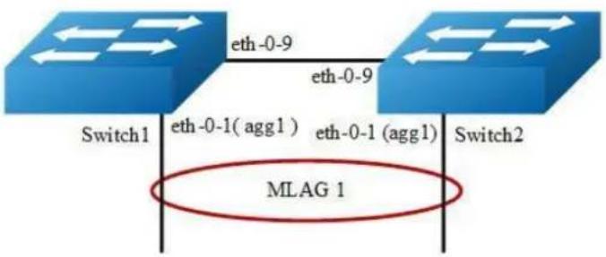
flowchart
graph TD
    A["Switch1"] -->|eth-0-9| B["Switch2"]
    B -->|eth-0-9| A
    C["MLAG 1"] --> A
    C --> B
Figure 3-25 MLAG
The configurations of Switch1-Switch2 are as blow. The configurations of these 2 Switches are same if there is no special description.
step 1 Enter the configure mode
Switch# configure terminal
step 2 Enter the vlan configure mode and create vlan
Switch(config)# vlan database
Switch(config-vlan)# vlan 10,4094
Switch(config-vlan)# exit
step 3 Create a static agg
Switch(config)# interface eth-0-1
Switch(config-if)# static-channel-group 1
Switch(config-if)# no shutdown
Switch(config-if)# exit
step 4 Set the attributes of the peer link interface
interface eth-0-9 will be set as the peer link interface later
Switch(config)# interface eth-0-9
Switch(config-if)# switchport mode trunk
Switch(config-if)# switchport trunk allowed vlan all
Switch(config-if)# spanning-tree port disable
Switch(config-if)# no shutdown
Switch(config-if)# exit
step 5 Bind the agg interface to the mlag
Switch(config)# interface agg1
Switch(config-if)# switchport mode trunk
Switch(config-if)# switchport trunk allowed vlan add 10
Switch(config-if)# mlag 1
Switch(config-if)# exit
step 6 Set the attributes of the vlan interface
Switch1:
Switch(config)# interface vlan4094
Switch(config-if)# ip address 12.1.1.1/24
Switch(config-if)# exit
Switch2:
Switch(config)# interface vlan4094
Switch(config-if)# ip address 12.1.1.2/24
Switch(config-if)# exit
step 7 Enter the mlag configure mode and set the attributes of the mlag
Switch1:
Switch(config)# mlag configuration
Switch(config-mlag)# peer-link eth-0-9
Switch(config-mlag)# peer-address 12.1.1.2
Switch(config-mlag)# exit
Switch2:
Switch(config)# mlag configuration
Switch(config-mlag)# peer-link eth-0-9
Switch(config-mlag)# peer-address 12.1.1.1
Switch(config-mlag)# end
step 8 Validation
Use the following command to display the information of mlag on Switch1
Switch# show mlag
MLAG configuration:
role : Master
local_sysid : ea90.aecc.cc00
mlag_sysid : ea90.aecc.cc00
peer-link : eth-0-9
peer conf : Yes

Switch# show mlag interface
mlagid local-if local-state remote-state
1 agg1 up up
Switch# show mlag peer
MLAG neighbor is 12.1.1.2, MLAG version 1
MLAG state = Established, up for 00:13:07
Last read 00:00:48, hold time is 240, keepalive interval is 60 seconds
Received 17 messages, Sent 19 messages
Open : received 1, sent 2
KAlive : received 15, sent 16
Fdb sync : received 0, sent 0
Failover : received 0, sent 0
Conf : received 1, sent 1

Connections established 1; dropped 0
Local host: 12.1.1.1, Local port: 61000
Foreign host: 12.1.1.2, Foreign port: 46157
remote_sysid: baa7.8606.8b00

Switch# show mac address-table
Mac Address Table

(*) - Security Entry
Vlan Mac Address Type Ports
Use the following command to display the information of mac address table on Switch1
Switch# show mlag
MLAG configuration:
role : Slave
local_sysid : baa7.8606.8b00
mlag_sysid : ea90.aecc.cc00
peer-link : eth-0-9
peer conf : Yes

Switch# show mlag interface
mlagid local-if local-state remote-state
1 agg1 up up

Switch# show mlag peer
MLAG neighbor is 12.1.1.1, MLAG version 1
MLAG state = Established, up for 00:14:29
Last read 00:00:48, hold time is 240, keepalive interval is 60 seconds
Received 19 messages, Sent 19 messages
Open : received 1, sent 1
KAlive : received 17, sent 17
Fdb sync : received 0, sent 0
Failover : received 0, sent 0
Conf : received 1, sent 1

Connections established 1; dropped 0
Local host: 12.1.1.2, Local port: 46157
Foreign host: 12.1.1.1, Foreign port: 61000
remote_sysid: ea90.aecc.cc00
Use the following command to display the information of mlag on Switch2:
Switch# show mac address-table
Mac Address Table

(*) - Security Entry
Vlan Mac Address Type Ports
3.15.3 Application cases
N/A
3.16 Configuring Hash Load-balance
3.16.1 Configuring Linkagg Hash
Overview
Linkagg can aggregate several physical interface to be a logical channel to enhance proformance and redundancy. When use linkagg transmit packets, it could be cause the same data stream transmitting on different physical interfaces. Because of that, the opposite equipment can receive packet disordering. In order to avoid this phenomenon, linkagg can accrod packets property to get a hash value, then it chooses appropriate physical interface to transmit packets. Besides this, it also can improve linkagg load balancing result.
Configuring Linkagg Hash Globally
The follow steps show how to set unicast and non-unicast linkagg hash on packets output interface globally and the configurations has the lowest priority.
step 1 Enter the configure mode
Switch# configure terminal
step 2 Set hash field
Switch(config)# hash-field user
Switch(config-hash-field)# 12 macsa
Switch(config-hash-field)# ip ipsa
Switch(config-hash-field)# exit
step 3 Set hash value global
Switch(config)# hash-value global
Switch(config-hash-value-global)# port-channel select user
Switch(config-hash-value-global)# end
step 4 Validation
Use the following command to display the information of hash field user:
Switch# show hash-field user
hash-field name: user
Option Control type

ipv6 address compress xor
hash seed user set (0)
hash arithmetic xor
hash symmetry disable
ip enable
ipv6 enable
mpls enable

hash field select
Packet HashField

12: macsa
ip: ipsa
ipv6: ipsa l4-sourceport ip-protocol ipda
gre: ipsa gre-key ipda
vxlan: vni outer-ipda outer-ipsa
nvgre: vsid outer-ipsa outer-ipda
mpls: top-label 2nd-label
vpws: top-label 2nd-label
vpls(inner-12): inner-macda inner-macsa
vpls(inner-13): inner-ipda inner-ipsa
13vpn: inner-ipsa inner-ipda
inner-ip-protocol inner-l4-sourceport
inner-l4-destport
Use the following command to display the information of hash value global:
Switch# show hash-value global
LBT:load balance type LBM :load balance mode
PT :packet type HF :hash field
HA :hash arithmetic
hash-value global
LBT LBM PT HF HA
port-channel - all user xor
ecmp - all ecmp xor
ecmp flow id all ecmp xor
entropy - all ecmp xor
Efd hash field select:
macsa macda
ipsa ipda
sourceport destport
ip-protocol
Configuring Linkagg Hash Input
The follow steps show how to set unicast linkagg hash on input interface and the configuration priority is higher than output. When the hash value is applied to in the input of linkagg port, the hash value will apply to the member port of linkagg port.
step 1 Enter the configure mode
Switch# configure terminal
step 2 Set hash field
Switch(config)# hash-field user
Switch(config-hash-field)# 12 macsa
Switch(config-hash-field)# ip ipsa
Switch(config-hash-field)# exit
step 3 Set hash value
Switch(config)# hash-value aaa
Switch(config-hash-value)# port-channel unicast select user
Switch(config-hash-value)# exit
step 4 Set hash value to interface
Switch(config)# interface range eth-0-1 - 2
Switch(config-if-range)# no shutdown
Switch(config-if-range)# static-channel-group 1
Switch(config-if-range)# exit
Switch(config)# interface agg 1
Switch(config-if)# load-balance hash-value aaa input
Switch(config-if)# exit
Switch(config)# interface eth-0-3
Switch(config-if)# load-balance hash-value aaa input
Switch(config-if)# end
step 5 Validation
Use the following command to display the information of hash field user:
Switch# show hash-field user
hash-field name: user
Option Control type

ipv6 address compress xor
hash seed user set (0)
hash arithmetic xor
hash symmetry disable
ip enable
ipv6 enable
mpls enable

hash field select
Packet HashField

12: macsa
ip: ipsa
ipv6: ipsa 14-sourceport ip-protocol ipda
gre: ipsa gre-key ipda
vxlan: vni outer-ipda outer-ipsa
nvgre: vsid outer-ipsa outer-ipda
mpls: top-label 2nd-label
vpws: top-label 2nd-label
vpls(inner-12): inner-macda inner-macsa
vpls (inner-13): inner-ipda inner-ipsa
13vpn: inner-ipsa inner-ipda
inner-ip-protocol inner-14-sourceport
inner-14-destport
Use the following command to display the information of hash value:
Switch# show hash-value aaa
LBT:load balance type LBM:load balance mode
PT :packet type HF :hash field
HA :hash arithmetic
hash-value name: aaa
LBT LBM PT HF HA
port-channel unicast all user xor
port-channel non-unicast all NOCFG NOCFG
ecmp - all NOCFG NOCFG
ecmp flow id all NOCFG NOCFG
Use the following command to display the application of hash value on port:
Switch# show hash-value interface-applied
eth-0-3
hash-value aaa input
agg1
hash-value aaa input
Configuring Linkagg Hash output
The follow steps show how to set unicast linkagg hash on output interface and the configuration priority is lower than input. It only can be applied on linkagg port.
step 1 Enter the configure mode
Switch# configure terminal
step 2 Set hash field
Switch(config)# hash-field user
Switch(config-hash-field)# 12 macsa
Switch(config-hash-field)# ip ipsa
Switch(config-hash-field)# exit
step 3 Set hash value
Switch(config)# hash-value aaa
Switch(config-hash-value)# port-channel unicast select user
Switch(config-hash-value)# exit
step 4 Set hash value to interface
Switch(config)# interface range eth-0-1 - 2
Switch(config-if-range)# no shutdown
Switch(config-if-range)# static-channel-group 1
Switch(config-if-range)# exit
Switch(config)# interface agg 1
Switch(config-if)# load-balance hash-value aaa output
Switch(config-if)# exit
step 5 Validation
Use the following command to display the information of hash field user:
Switch# show hash-field user
hash-field name: user
Option Control type

ipv6 address compress xor
hash seed user set (0)
hash arithmetic xor
hash symmetry disable
ip enable
ipv6 enable
mpls enable

hash field select
Packet HashField

12: macsa
ip: ipsa
ipv6: ipsa 14-sourceport ip-protocol ipda
gre: ipsa gre-key ipda
vxlan: vni outer-ipda outer-ipsa
nvgre: vsid outer-ipsa outer-ipda
mpls: top-label 2nd-label
vpws: top-label 2nd-label
vpls(inner-12): inner-macda inner-macsa
vpls(inner-13): inner-ipda inner-ipsa
13vpn: inner-ipsa inner-ipda
inner-ip-protocol inner-l4-sourceport
inner-l4-destport
Use the following command to display the information of hash value:
Switch# show hash-value aaa
LBT:load balance type LBM:load balance mode
PT :packet type HF :hash field
HA :hash arithmetic
hash-value name: aaa
LBT LBM PT HF HA
port-channel unicast all user xor
port-channel non-unicast all NOCFG NOCFG
ecmp - all NOCFG NOCFG
ecmp flow id all NOCFG NOCFG
Use the following command to display the application of hash value on port:
Switch# show hash-value interface-applied
agg1
hash-value aaa output
Configuring Linkagg Hash ACL
The follow steps show how to make linkagg hash configurations to be a ACL action and the configurations have the highest priority.
step 1 Enter the configure mode
Switch# configure terminal
step 2 Set hash field
Switch(config)# hash-field user
Switch(config-hash-field)# 12 macsa
Switch(config-hash-field)# ip ipsa
Switch(config-hash-field)# exit
step 3 Set hash value
Switch(config)# hash-value aaa
Switch(config-hash-value)# port-channel unicast select user
Switch(config-hash-value)# exit
step 4 Add acl action to interface and set hash value to interface
Switch(config)# mac access-list mac
Switch(config-mac-acl)# permit src-mac host 0.0.1 dest-mac any
Switch(config-mac-acl)# exit
Switch(config)# class-map cmap1
Switch(config-cmap)# match access-group mac
Switch(config-cmap)# exit
Switch(config)# policy-map pmap1
Switch(config-pmap)# class cmap1
Switch(config-pmap-c)# load-balance hash-value aaa
Switch(config-pmap-c)# port-channel load-balance round-robin disable
Switch(config-pmap-c)# exit
Switch(config-pmap)# exit
Switch(config)# interface eth-0-3
Switch(config-if)# no shutdown
Switch(config-if)# service-policy input pmap1
Switch(config-if)# end
step 5 Validation
Use the following command to display the information of hash field user:
Switch# show hash-field user
hash-field name: user
Option Control type
ipv6 address compress xor
hash seed user set (0)
hash arithmetic xor
hash symmetry disable
ip enable
ipv6 enable
mpls enable
hash field select
Packet HashField
12: macsa
ip: ipsa
ipv6: ipsa 14-sourceport ip-protocol ipda
gre: ipsa gre-key ipda
vxlan: vni outer-ipda outer-ipsa
nvgre: vsid outer-ipsa outer-ipda
mpls: top-label 2nd-label
vpws: top-label 2nd-label
vpls (inner-12): inner-macda inner-macsa
vpls (inner-13): inner-ipda inner-ipsa
13vpn: inner-ipsa inner-ipda inner-ip-protocol inner-14-sourceport inner-14-destport
Use the following command to display the information of hash value:
Switch# show hash-value aaa
LBT:load balance type LBM:load balance mode
PT :packet type HF :hash field
HA :hash arithmetic
hash-value name: aaa
LBT LBM PT HF HA
port-channel unicast all user xor
port-channel non-unicast all NOCFG NOCFG
ecmp - all NOCFG NOCFG
ecmp flow id all NOCFG NOCFG
Use the following command to display the information of ACL:
Switch# show running-config
mac access-list mac
10 permit src-mac host 0000.0000.0001 dest-mac any
!
hash-field user
12 macsa
ip ipsa
!
hash-value aaa
port-channel unicast select user
!
class-map match-any cmap1
match access-group mac
!
policy-map pmap1
class cmap1
port-channel load-balance round-robin disable
load-balance hash-value aaa
!
interface eth-0-3
service-policy input pmap1
!
interface null0
Configuring Non-unicast Linkagg Hash
The follow steps show how to set non-unicast linkagg hash on input interface and the configuration does not support on output. When the hash value is applied to in the input of linkagg port, the hash value will apply to the member port of linkagg port.
step 1 Enter the configure mode
Switch# configure terminal
step 2 Set hash field
Switch(config)# hash-field user
Switch(config-hash-field)# 12 macsa
Switch(config-hash-field)# ip ipsa
Switch(config-hash-field)# exit
step 3 Set hash value
Switch(config)# hash-value aaa
Switch(config-hash-value)# port-channel non-unicast select user
Switch(config-hash-value)# exit
step 4 Set hash value to interface
Switch(config)# interface range eth-0-1 - 2
Switch(config-if-range)# no shutdown
Switch(config-if-range)# static-channel-group 1
Switch(config-if-range)# exit
Switch(config)# interface agg 1
Switch(config-if)# load-balance hash-value aaa input
Switch(config-if)# exit
Switch(config)# interface eth-0-3
Switch(config-if)# load-balance hash-value aaa input
Switch(config-if)# end
step 5 Validation
Use the following command to display the information of hash field user:
Switch# show hash-field user
hash-field name: user
Option Control type
ipv6 address compress xor
hash seed user set (0)
hash arithmetic xor
hash symmetry disable
ip enable
ipv6 enable
mpls enable
hash field select
Packet HashField
12: macsa
ip: ipsa
ipv6: ipsa ipda
14-sourceport 14-destport
ip-protocol
gre: ipsa ipda
gre-key
vxlan: vni outer-ipda outer-ipsa
nvgre: vsid outer-ipda
mpls: top-label 2nd-label
vpws: top-label 2nd-label
vpls (inner-12): inner-macda inner-macsa
vpls (inner-13): inner-ipda inner-ipsa
l3vpn: inner-ipsa inner-ipd a inner-14-sourceport
inner-ip-protocol inner-l4-destport
Use the following command to display the information of hash value:
Switch# show hash-value aaa
LBT:load balance type LBM:load balance mode
PT :packet type HF :hash field
HA :hash arithmetic
hash-value name: aaa
LBT LBM PT HF HA
port-channel unicast all NOCFG NOCFG
port-channel non-unicast all user xor
ecmp - all NOCFG NOCFG
ecmp flow id all NOCFG NOCFG
Use the following command to display the application of hash value on port:
Use the following command to display the application of hash value on port:
Switch# show hash-value interface-applied
eth-0-3
hash-value aaa input
agg1
hash-value aaa input
3.16.2 Configuring ECMP Hash
Overview
Equal-cost multi-path routing is a routing strategy where next-hop packet forwarding to a single destination can occur over multiple “best paths” which tie for top place in routing metric calculations. Multi-path routing can be used in conjunction with most routing protocols, because it is a per-hop decision limited to a single router. It can substantially increase bandwidth by load-balancing traffic over multiple paths. Ecmp hash is used to do load balance.
Configuring ECMP Hash Globally
The follow steps show how to set ecmp hash globally and the configurations has the lowest priority.
step 1 Enter the configure mode
Switch# configure terminal
step 2 Set hash field
Switch(config)# hash-field user
Switch(config-hash-field)# 12 macsa
Switch(config-hash-field)# ip ipsa
Switch(config-hash-field)# exit
step 3 Set hash value global
Switch(config)# hash-value global
Switch(config-hash-value-global)# ecmp select user
Switch(config-hash-value-global)# end
step 4 Validation
Use the following command to display the information of hash field user:
Switch# show hash-field user
hash-field name: user
Option Control type
ipv6 address compress xor
hash seed user set (0)
hash arithmetic xor
hash symmetry disable
ip enable
ipv6 enable
mpls enable
hash field select
Packet HashField
12: macsa
ip: ipsa
ipv6: ipsa 14-sourceport ip-protocol ipda
gre: ipsa gre-key ipda
vxlan: vni outer-ipda outer-ipsa
nvgre: vsid outer-ipsa outer-ipda
mpls: top-label 2nd-label
vpws: top-label 2nd-label
vpls (inner-12): inner-macda inner-macsa
vpls (inner-13): inner-ipda inner-ipsa
l3vpn: inner-ipsa inner-ipda inner-ipd inner-ip-protocol inner-14-sourceport inner-l4-destport
Use the following command to display the information of hash value global:
Switch# show hash-value global
LBT:load balance type LBM :load balance mode
PT :packet type HF :hash field
HA :hash arithmetic
hash-value global
LBT LBM PT HF HA
port-channel - all port-channel xor
ecmp - all user xor
ecmp flow id all user xor
entropy - all ecmp xor
Efd hash field select:
macsa macda
ipsa ipda
sourceport destport
ip-protocol
Configuring ECMP Hash Input
The follow steps show how to set ECMP hash on input interface and the configuration priority is higher than global configuration.
step 1 Enter the configure mode
Switch# configure terminal
step 2 Set hash field
Switch(config)# hash-field user
Switch(config-hash-field)# 12 macsa
Switch(config-hash-field)# ip ipsa
Switch(config-hash-field)# exit
step 3 Set hash value
Switch(config)# hash-value bbb
Switch(config-hash-value)# ecmp select user
Switch(config-hash-value)# exit
step 4 Set hash value to interface
Switch(config)# interface eth-0-1
Switch(config-if)# no shutdown
Switch(config-if)# load-balance hash-value bbb input
Switch(config-if)# end
step 5 Validation
Use the following command to display the information of hash field user:
Switch# show hash-field user
hash-field name: user
Option Control type
ipv6 address compress xor
hash seed user set (0)
hash arithmetic xor
hash symmetry disable
ip enable
ipv6 enable
mpls enable
hash field select
Packet HashField
12: macsa
ip: ipsa
ipv6: ipsa 14-sourceport ip-protocol ipda
gre: ipsa gre-key ipda
vxlan: vni outer-ipda outer-ipsa
nvgre: vsid outer-ipsa outer-ipda
mpls: top-label 2nd-label
vpws: top-label 2nd-label
vpls (inner-12): inner-macda inner-macsa
vpls (inner-13): inner-ipda inner-ipsa
13vpn: inner-ipsa inner-ipda inner-ip-protocol inner-14-sourceport inner-14-destport
Use the following command to display the information of hash value:
Switch# show hash-value bbb
LBT:load balance type LBM:load balance mode
PT :packet type HF :hash field
HA :hash arithmetic
hash-value name: bbb
LBT LBM PT HF HA
port-channel unicast all NOCFG NOCFG
port-channel non-unicast all NOCFG NOCFG
ecmp - all user xor
ecmp flow id all NOCFG NOCFG
Use the following command to display the application of hash value on port:
Switch# show hash-value interface-applied
eth-0-1
hash-value bbb input
Configuring ECMP Hash input
The follow steps show how to make ECMP hash configurations to be a ACL action and the configurations have the highest priority.
step 1 Enter the configure mode
Switch# configure terminal
step 2 Set hash field
Switch(config)# hash-field user
Switch(config-hash-field)# 12 macsa
Switch(config-hash-field)# ip ipsa
Switch(config-hash-field)# exit
step 3 Set hash value
Switch(config)# hash-value bbb
Switch(config-hash-value)# ecmp select user
Switch(config-hash-value)# exit
step 4 Add acl action to interface and set hash value to interface
Switch(config)# mac access-list mac
Switch(config-mac-acl)# permit src-mac host 0.0.1 dest-mac any
Switch(config-mac-acl)# exit
Switch(config)# class-map cmap1
Switch(config-cmap)# match access-group mac
Switch(config-cmap)# exit
Switch(config)# policy-map pmap1
Switch(config-pmap)# class cmap1
Switch(config-pmap-c)# load-balance hash-value bbb
Switch(config-pmap-c)# ecmp load-balance round-robin disable
Switch(config-pmap-c)# exit
Switch(config-pmap)# exit
Switch(config)# interface eth-0-1
Switch(config-if)# no shutdown
Switch(config-if)# service-policy input pmap1
Switch(config-if)# end
step 5 Validation
Use the following command to display the information of hash field user:
Switch# show hash-field user
hash-field name: user
Option Control type
ipv6 address compress xor
hash seed user set (0)
hash arithmetic xor
hash symmetry disable
ip enable
ipv6 enable
mpls enable
hash field select
Packet HashField
12: macsa
ip: ipsa
ipv6: ipsa 14-sourceport ip-protocol ipda
gre: ipsa gre-key ipda
vxlan: vni outer-ipda outer-ipsa
nvgre: vsid outer-ipsa outer-ipda
mpls: top-label 2nd-label
vpws: top-label 2nd-label
vpls(inner-12): inner-macda inner-macsa
vpls(inner-13): inner-ipda inner-ipsa
13vpn: inner-ipsa inner-ipda inner-ipd inner-l4-sourceport
inner-ip-protocol inner-l4-destport
Use the following command to display the information of hash value:
Switch# show hash-value bbb
LBT:load balance type LBM:load balance mode
PT :packet type HF :hash field
HA :hash arithmetic
hash-value name: bbb
LBT LBM PT HF HA
port-channel unicast all NOCFG NOCFG
port-channel non-unicast all NOCFG NOCFG
ecmp - all user xor
ecmp flow id all NOCFG NOCFG
Use the following command to display the information of ACL:
mac access-list mac
10 permit src-mac host 0000.0000.0001 dest-mac any
!
hash-field user
l2 macsa
ip ipsa
!
hash-value bbb
ecmp select user
!
class-map match-any cmap1
match access-group mac
!
policy-map pmap1
class cmap1
ecmp load-balance round-robin disable
load-balance hash-value bbb
!
interface eth-0-1
service-policy input pmap1
!
interface null0
!
3.16.3 Configuring ECMP Hash
Overview
Elephant Flow Detect(EFD). According to the academic institutions of the actual data center of the study found that more than 80% of the data center bandwidth is occupied by elephant flow, the bandwidth and transmission cache of these flow is large, but not sensitive to delay, which is sensitive to delay The flow caused a great impact.EFD hash is used to detect elephant flow by recognising packet features.
Configuring EFD Hash Globally
The follow steps show how to select packet features for EFD hash globally.
step 1 Enter the configure mode
Switch# configure terminal
step 2 Set hash global
Switch(config)# hash-value global
Switch(config-hash-value-global)# efd select ipsa macsa
Switch(config-hash-value-global)# end
step 3 Validation
Use the following command to display the information of hash value global:
Switch# show hash-value global
LBT:load balance type LBM :load balance mode
PT :packet type HF :hash field
HA :hash arithmetic
hash-value global
LBT LBM PT HF HA
port-channel - all port-channel xor
ecmp - all ecmp xor
ecmp flow id all ecmp xor
entropy - all ecmp xor
Efd hash field select:
macsa ipsa
3.17 Configuring PORT-XCONNECT
3.17.1 Overview
Function Introduction
This feature can forward the packet directly according to the destination-interface configured without looking up any table items and forwarding.
Only physical and aggregate port are currently supported.
Principle Description
N/A
3.17.2 Configuration
step 1 Enter the configure mode
Switch# configure terminal
step 2 Enter the interface mode and no shutdown
Switch(config)# interface range eth-0-1, eth-0-2
Switch(config-if-range)# no shutdown
step 3 Set eth-0-1 port-xconnect destination interface
Switch(config)# interface eth-0-1
Switch(config-if)# port-xconnect destination-interface eth-0-2
Switch(config-if)# end
step 4 Display configuration
Switch# show running-config
Building configuration...
version 5.3.9.18
!
no service password-encryption
!
!
!
!
!
!
temperature 0 0 0
!
vlan database
!
interface eth-0-1
port-xconnect destination-interface eth-0-2
!
interface eth-0-2
!
interface eth-0-3
Switch#
3.17.3 Application cases
N/A
4 IP Service Configuration Guide
4.1 Configuring Arp
4.1.1 Overview
Function Introduction
The Address Resolution Protocol (ARP) is a protocol used to dynamically map between Internet host addresses and Ethernet addresses. ARP caches Internet- Ethernet address mappings. When an interface requests a mapping for an address not in the cache, ARP queues the message, which requires the mapping, and broadcasts a message on the associated network requesting the address mapping. If a response is provided, the new mapping is cached and any pending message is transmitted. ARP will queue at most one packet while waiting for a response to a mapping request; only the most recently transmitted packet is kept. If the target host does not respond after 3 requests, the host is considered to be down, allowing an error to be returned to transmission attempts during this interval. If a target host does not send message for a period (normally one hour), the host is considered to be uncertainty, and several requests (normally 6, 3 unicast and 3 broadcast) will send to the host before delete the ARP entry. ARP entries may be added, deleted or changed manually. Manually added entries may be temporary or permanent.
Principle Description
N/A
4.1.2 Configuration
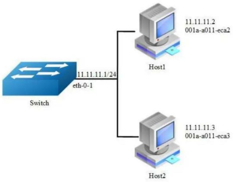
flowchart
graph TD
A["Switch"] -->|eth-0-1 11.11.11.1/24| B["Host1"]
A -->|eth-0-1| C["Host2"]
B -->|001a-a011-eca2| D["Computer"]
C -->|001a-a011-eca3| E["Computer"]
Figure 4-1 arp
In this configuration example, interface eth-0-1 assigned with address 11.11.11.1/24, on subnet 11.11.11.0/24, there are two hosts, and their IP addresses are 11.11.11.2, 11.11.11.3, MAC address are 001a-a011-eca2, 001a-a011-eca3. ARP entry of host 11.11.11.2 is added manually, the entry of host 11.11.11.3 is added dynamically. Time-out period of ARP entries for interface eth-0-1 configure to 20 minutes, ARP request retry delay on interface eth-0-1 configure to 2 seconds.
step 1 Enter the configure mode
Switch# configure terminal
step 2 Configure the layer 3 interface and set the ip address
Switch(config)# interface eth-0-1
Switch(config-if)# no switchport
Switch(config-if)# ip address 11.11.11.1/24
step 3 Configure arp aging timeout value and the arp retry interval value
Switch(config-if)# arp timeout 1200
Switch(config-if)# arp retry-interval 2
Switch(config-if)# exit
step 4 Add a static arp entry
Switch(config)# arp 11.11.11.2 1a.a011.eca2
step 5 Exit the configure mode
Switch(config)# end
step 6 Validation
Use the following command to display the information of the arp entry:
Switch# show ip arp
Protocol Address Age (min) Hardware Addr Interface
Internet 11.11.11.2 - 001a.a011.eca2 eth-0-1
Switch# show ip arp summary
1 IP ARP entries, with 0 of them incomplete
(Static:0, Dynamic:0, Interface:1)
ARP Pkt Received is: 0
ARP Pkt Send number is: 0
ARP Pkt Dicard number is: 0
Use the following command to display the information of the arp configurations on the interface:
Switch# show interface eth-0-1
Interface eth-0-1
Interface current state: Administratively DOWN
Hardware is Ethernet, address is 6c02.530c.2300 (bia 6c02.530c.2300)
Bandwidth 1000000 kbits
Index 1, Metric 1, Encapsulation ARPA
Speed - Auto, Duplex - Auto, Media type is 1000BASE_T
Link speed type is autonegotiation, Link duplex type is autonegotiation
Input flow-control is off, output flow-control is off
The Maximum Frame Size is 1534 bytes
VRF binding: not bound
Label switching is disabled
No virtual circuit configured
VRRP master of : VRRP is not configured on this interface
ARP timeout 00:20:00, ARP retry interval 2s
5 minute input rate 0 bits/sec, 0 packets/sec
5 minute output rate 0 bits/sec, 0 packets/sec
0 packets input, 0 bytes
Received 0 unicast, 0 broadcast, 0 multicast
0 runts, 0 giants, 0 input errors, 0 CRC
0 frame, 0 overrun, 0 pause input
0 input packets with dribble condition detected
0 packets output, 0 bytes
Transmitted 0 unicast, 0 broadcast, 0 multicast
0 underruns, 0 output errors, 0 pause output
4.1.3 Application cases
N/A
4.2 Configuring Arp proxy
4.2.1 Overview
Function Introduction
Proxy ARP, the most common method for learning about other routes, enables an Ethernet host with no routing information to communicate with hosts on other networks or subnets. The host assumes that all hosts are on the same local Ethernet and that they can use ARP to determine their MAC addresses. If a switch receives an ARP request for a host that is not on the same network as the sender, the switch evaluates whether it has the best route to that host. If it does, it sends an ARP reply packet with its own Ethernet MAC address, and the host that sent the request sends the packet to the switch, which forwards it to the intended host. Proxy ARP treats all networks as if they are local and performs ARP requests for every IP address. Proxy ARP can be separated to 2 parts: Proxy ARP and local Proxy ARP. Local Proxy ARP is always used in the topology where the Device is enabled port isolate but still need to do communicating via routing. Internet Control Message Protocol (ICMP) redirects are disabled on interfaces where the local proxy ARP feature is enabled.
Principle Description
N/A
4.2.2 Configuration
Configuring ARP Proxy
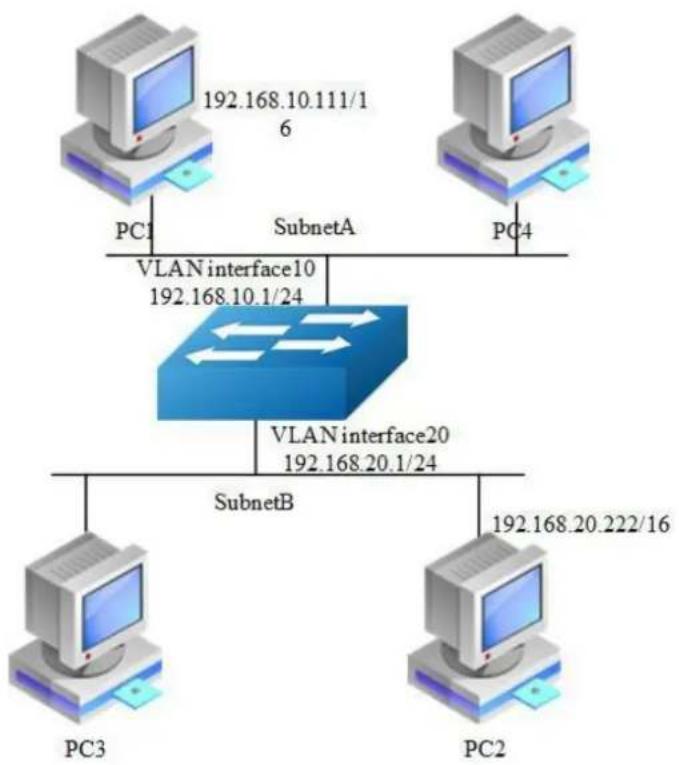
flowchart
graph TD
A["PC1"] --> B["VLAN interface10\n192.168.10.1/24"]
C["PC2"] --> D["VLAN interface20\n192.168.20.1/24"]
E["PC3"] --> F["SubnetB"]
G["SubnetA"] --> B
H["SubnetB"] --> D
I["PC4"] --> J["SubnetA"]
K["PC1"] --> L["SubnetA"]
M["PC2"] --> N["SubnetB"]
O["PC3"] --> P["SubnetB"]
Q["PC4"] --> R["SubnetA"]
Figure 4-2 arp proxy
As seen in the above topology, PC1 is belonged to VLAN10 and PC2 is belonged to VLAN20. If ARP proxy feature is not enabled, then PC1 and PC2 can not communicate with each other. As following, these steps are shown to enable ARP proxy feature for both VLAN interface 10 and VLAN interface 20.
step 1 Enter the configure mode
Switch# configure terminal
step 2 Enter the vlan configure mode and create vlan
Switch(config)# vlan database Switch(config-vlan)# vlan 10,20 Switch(config-vlan)# exit
step 3 Enter the interface configure mode, set the switch port mode and bind to the vlan
Switch(config)# interface eth-0-22
Switch(config-if)# switchport access vlan 10
Switch(config-if)# no shutdown
Switch(config-if)# exit
Switch(config)# interface eth-0-23
Switch(config-if)# switchport access vlan 20
Switch(config-if)# no shutdown
Switch(config-if)# exit
step 4 Create the vlan interface, configure the ip address, and enable arp proxy
Switch(config)# interface vlan 10
Switch(config-if)# ip address 192.168.10.1/24
Switch(config-if)# proxy-arp enable
Switch(config-if)# exit
Switch(config)# interface vlan 20
Switch(config-if)# ip address 192.168.20.1/24
Switch(config-if)# proxy-arp enable
Switch(config-if)# exit
step 5 Exit the configure mode
Switch(config)# end
step 6 Validation
Use the following command to display the information of the arp proxy configuration on the switch:
Switch# show ip interface vlan 10
Interface vlan10
Interface current state: UP
Internet address(es):
192.168.10.1/24 broadcast 192.168.10.255
Joined group address(es):
224.0.0.1
The maximum transmit unit is 1500 bytes
ICMP error messages limited to one every 1000 milliseconds
ICMP redirects are always sent
ICMP unreachables are always sent
ICMP mask replies are always sent
ARP timeout 01:00:00, ARP retry interval ls
ARP Proxy is enabled, Local ARP Proxy is disabled
VRRP master of : VRRP is not configured on this interface
Switch# show ip interface vlan 20
Interface vlan20
Interface current state: UP
Internet address(es):
192.168.20.1/24 broadcast 192.168.20.255
Joined group address(es):
224.0.0.1
The maximum transmit unit is 1500 bytes
ICMP error messages limited to one every 1000 milliseconds
ICMP redirects are always sent
ICMP unreachables are always sent
ICMP mask replies are always sent
ARP timeout 01:00:00, ARP retry interval 1s
ARP Proxy is enabled, Local ARP Proxy is disabled
VRRP master of : VRRP is not configured on this interface
Use the following command to display the information of the arp entry on the switch:
Switch# show ip arp
Protocol Address Age (min) Hardware Addr Interface
Internet 192.168.10.1 - 7cc3.11f1.aa00 vlan10
Internet 192.168.10.111 5 0cf9.11b6.6e2e vlan10
Internet 192.168.20.1 - 7cc3.11f1.aa00 vlan20
Internet 192.168.20.222 6 5a94.031f.2357 vlan20
Use the following command to display the information on PC1:
[Host:~]$ ifconfig eth0
eth0 Link encap:Ethernet HWaddr 0C:F9:11:B6:6E:2E
inet addr:192.168.10.111 Bcast:192.168.255.255 Mask:255.255.0.0
UP BROADCAST RUNNING MULTICAST MTU:1600 Metric:1
RX packets:11 errors:0 dropped:0 overruns:0 frame:0
TX packets:10 errors:0 dropped:0 overruns:0 carrier:0
collisions:0 txqueuelen:1000
RX bytes:588 (588.0 b) TX bytes:700 (700.0 b)
Interrupt:5
[Host:~]$ arp -a
? (192.168.20.222) at 7c:c3:11:f1:aa:00 [ether] on eth0
[Host: ~]$ route -v
Kernel IP routing table
Destination Gateway Genmask Flags Metric Ref Use Iface
192.168.0.0 * 255.255.0.0 U 0 0 0 eth0
[Host:~]$ ping 192.168.20.222
PING 192.168.20.222 (192.168.20.222) 56(84) bytes of data.
64 bytes from 192.168.20.222: icmp_seq=0 ttl=63 time=189 ms
64 bytes from 192.168.20.222: icmp_seq=1 ttl=63 time=65.2 ms
--- 192.168.20.222 ping statistics ---
2 packets transmitted, 2 received, 0% packet loss, time 1000ms
rtt min/avg/max/mdev = 65.209/127.226/189.244/62.018 ms, pipe 2
Use the following command to display the information on PC2:
[Host:~]$ ifconfig eth0
eth0 Link encap:Ethernet HWaddr 5A:94:03:1F:23:57
inet addr:192.168.20.222 Bcast:192.168.255.255 Mask:255.255.0.0
UP BROADCAST RUNNING MULTICAST MTU:1600 Metric:1
RX packets:14 errors:0 dropped:0 overruns:0 frame:0
TX packets:17 errors:0 dropped:0 overruns:0 carrier:0
collisions:0 txqueuelen:1000
RX bytes:784 (784.0 b) TX bytes:1174 (1.1 KiB)
Interrupt:5
[Host:~]$ arp -a
? (192.168.10.111) at 7c:c3:11:f1:aa:00 [ether] on eth0
[Host: ~]$ route -v
Kernel IP routing table
Destination Gateway Genmask Flags Metric Ref Use Iface
192.168.0.0 * 255.255.0.0 U 0 0 0 eth0
[Host: ~]$ ping 192.168.10.111
PING 192.168.10.111 (192.168.10.111) 56(84) bytes of data.
64 bytes from 192.168.10.111: icmp_seq=0 ttl=63 time=53.8 ms
64 bytes from 192.168.10.111: icmp_seq=1 ttl=63 time=65.8 ms
--- 192.168.10.111 ping statistics ---
2 packets transmitted, 2 received, 0% packet loss, time 1007ms
rtt min/avg/max/mdev = 53.832/59.842/65.852/6.010 ms, pipe 2
Configuring Local ARP Proxy
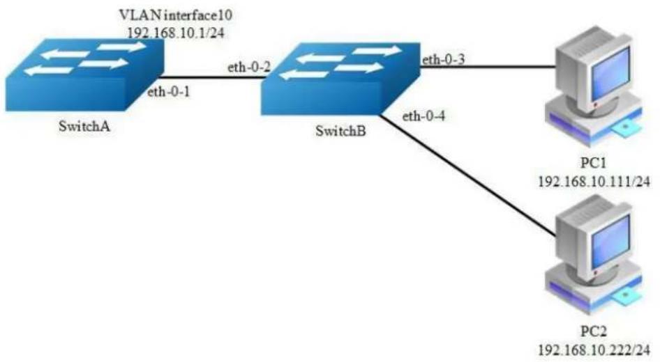
flowchart
graph TD
A["SwitchA"] -->|eth-0-1| B["SwitchB"]
B -->|eth-0-2| A
B -->|eth-0-3| C["PC1"]
B -->|eth-0-4| D["PC2"]
C -->|192.168.10.111/24| E["Computer"]
D -->|192.168.10.222/24| F["Computer"]
Figure 4-3 local arp proxy
As the above topology, eth-0-2, eth-0-3 and eth-0-4 are belonging to VLAN 10. eth-0-3 and eth-0-4 are both in port isolate group 1, and eth-0-2 is in port isolate group 3, so packets received in eth-0-3 can not flood to eth-0-4, but packets received in eth-0-2 can flood to both eth-0-3 and eth-0-4. PC1 is connecting with port eth-0-3
and PC2 is connecting with port eth-0-4.Configure as the following step for communicating with PC1 and PC2.
The configurations of switch A and switch B are same if there is no special description.
step 1 Enter the configure mode
Switch# configure terminal
step 2 Enter the vlan configure mode and create vlan
Switch(config)# vlan database
Switch(config-vlan)# vlan 10
Switch(config-vlan)# exit
step 3 Enter the interface configure mode, set the switch port mode and bind to the vlan
Switch A configuration:
Switch(config)# interface eth-0-1
Switch(config-if)# switchport access vlan 10
Switch(config-if)# no shutdown
Switch(config-if)# exit
Switch B configuration:
Switch(config)# interface range eth-0-2 - 4
Switch(config-if-range# switchport access vlan 10
Switch(config-if-range# no shutdown
Switch(config-if-range# exit
step 4 Create the vlan interface, configure the ip address, and enable local arp proxy
Switch A configuration:
Switch(config)# interface vlan 10
Switch(config-if)# ip address 192.168.10.1/24
Switch(config-if)# local-proxy-arp enable
Switch(config-if)# exit
step 5 Configuring port isolation(optional)
Switch B configuration:
After configuring port isolation as blow, eth-0-3 and eth-0-4 on switchB are isolated in layer 2 network.
Switch(config)# port-isolate mode 12
Switch(config)# interface eth-0-3 - 4
Switch(config-if-range# port-isolate group 1
Switch(config-if-range# exit
Switch(config)# interface eth-0-2
Switch(config-if)# port-isolate group 3
Switch(config-if)# exit
step 6 Validation
Use the following command to display the information of the arp entry on switchA:
Switch# show ip arp
Protocol Address Age (min) Hardware Addr Interface
Internet 192.168.10.1 - eeb4.2a8d.6c00 vlan10
Internet 192.168.10.111 0 34b0.b279.5f67 vlan10
Internet 192.168.10.222 0 2a65.9618.57fa vlan10
Use the following command to display the information of the arp configurations on the interface of switchA:
Switch# show ip interface vlan 10
Interface vlan10
Interface current state: UP
Internet address(cs):
192.168.10.1/24 broadcast 192.168.10.255
Joined group address(cs):
224.0.0.1
The maximum transmit unit is 1500 bytes
ICMP error messages limited to one every 1000 milliseconds
ICMP redirects are never sent
ICMP unreachables are always sent
ICMP mask replies are always sent
ARP timeout 01:00:00, ARP retry interval ls
ARP Proxy is disabled, Local ARP Proxy is enabled
VRRP master of : VRRP is not configured on this interface
Use the following command to display the information on PC1:
[Host: ~]$ ifconfig eth0
eth0 Link encap:Ethernet HWaddr 34:B0:B2:79:5F:67
inet addr:192.168.10.111 Bcast:192.168.10.255 Mask:255.255.255.0
UP BROADCAST RUNNING MULTICAST MTU:1600 Metric:1
RX packets:22 errors:0 dropped:0 overruns:0 frame:0
TX packets:28 errors:0 dropped:0 overruns:0 carrier:0
collisions:0 txqueuelen:1000
RX bytes:1344 (1.3 KiB) TX bytes:2240 (2.1 KiB)
Interrupt:5
[Host: ~]$ arp -a
? (192.168.10.222) at ee:b4:2a:8d:6c:00 [ether] on eth0
[Host: ~]$ ping 192.168.10.222
PING 192.168.10.222 (192.168.10.222) 56(84) bytes of data.
64 bytes from 192.168.10.222: icmp_seq=0 ttl=63 time=131 ms
64 bytes from 192.168.10.222: icmp_seq=1 ttl=63 time=159 ms
--- 192.168.10.222 ping statistics ---
2 packets transmitted, 2 received, 0% packet loss, time 1003ms
rtt min/avg/max/mdev = 131.078/145.266/159.454/14.188 ms, pipe 2
Use the following command to display the information on PC2:
[Host:~]$ ifconfig eth0
eth0 Link encap:Ethernet HWaddr 2A:65:96:18:57:FA
inet addr:192.168.10.222 Bcast:192.168.10.255 Mask:255.255.255.0
UP BROADCAST RUNNING MULTICAST MTU:1600 Metric:1
RX packets:19 errors:0 dropped:0 overruns:0 frame:0
TX packets:20 errors:0 dropped:0 overruns:0 carrier:0
collisions:0 txquuelen:1000
RX bytes:1148 (1.1 KiB) TX bytes:1524 (1.4 KiB)
Interrupt:5
[Host:~]$ arp -a
? (192.168.10.111) at ee:b4:2a:8d:6c:00 [ether] on eth0
[Host: ~]$ ping 192.168.10.111
PING 192.168.10.111 (192.168.10.111) 56(84) bytes of data.
64 bytes from 192.168.10.111: icmp_seq=0 ttl=63 time=198 ms
64 bytes from 192.168.10.111: icmp_seq=1 ttl=63 time=140 ms
64 bytes from 192.168.10.111: icmp_seq=2 ttl=63 time=146 ms
--- 192.168.10.111 ping statistics ---
3 packets transmitted, 3 received, 0% packet loss, time 2008ms
rtt min/avg/max/mdev = 140.196/161.959/198.912/26.267 ms, pipe 2
4.2.3 Application cases
N/A
4.3 Configuring DHCP Client
4.3.1 Overview
Function Introduction
Dynamic Host Configuration Protocol(DHCP) client can acquire IP address and configuration dynamically from DHCP server by DHCP. If client and server is on the same physical subnet, client can communicate with server directly, otherwise they need DHCP relay agent which is used to forward DHCP messages. DHCP client can
request IP address from DHCP server by broadcasting DHCP messages. After received IP address and lease correspond to it, client will configure itself and set the expired time. When half past the lease, client will sent DHCP messages for a new lease to use the IP address continually. If it success, DHCP client will renew the lease. DHCP client can send option request to server, which may be one or several of router, static-route, classless-static-route, classless-static-route-ms, tftp-server-address, dns-nameserver, domain-name, netbios-nameserver and vendor-specific. By default, options include router, static-route, classless-static-route, classless-static-route-ms, tftp-server-address will be requested from server. We can cancel one or several of these option requests by command.
Principle Description
N/A
4.3.2 Configuration
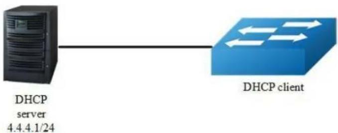
flowchart
graph LR
A["DHCP server 4.4.4.1/24"] --> B["DHCP client"]
Figure 4-4 dhcp client
step 1 Enter the configure mode
Switch# configure terminal
step 2 Enter the interface configure mode
Switch(config)# interface eth-0-1 Switch(config-if)# no switchport Switch(config-if)# no shutdown
step 3 disable static-route and enable DHCP client
Switch(config-if)# no dhcp client request static-route Switch(config-if)# ip address dhcp
step 4 Exit the configure mode
Switch(config-if)# end
step 5 Validation
Check interface configuration:
Switch# show running-config interface eth-0-1
Building configuration...
!
interface eth-0-1
no switchport
ip address dhcp
no dhcp client request static-route
!
Check all DHCP client status:
Switch# show dhcp client verbose
DHCP client informations:
eth-0-1 DHCP client information:
Current state: BOUND
Allocated IP: 4.4.4.199 255.255.255.0
Lease/renewal/rebinding: 1187/517/1037 seconds
Lease from 2011-11-18 05:59:59 to 2011-11-18 06:19:59
Will Renewal in 0 days 0 hours 8 minutes 37 seconds
DHCP server: 4.4.4.1
Transaction ID: 0x68857f54
Client ID: switch-7e39.3457.b700-eth-0-1
Show DHCP client statistics:
Switch# show dhcp client statistics
DHCP client packet statistics:
DHCP OFFERS received: 1
DHCP ACKs received: 2
DHCP NAKs received: 0
DHCP Others received: 0
DHCP DISCOVER sent: 1
DHCP DECLINE sent: 0
DHCP RELEASE sent: 0
DHCP REQUEST sent: 2
DHCP packet send failed: 0
4.3.3 Application cases
N/A
4.4 Configuring DHCP Relay
4.4.1 Overview
Function Introduction
DHCP relay agent is any host that forwards DHCP packets between clients and servers. Relay agents are used to forward requests and replies between clients and servers when they are not on the same physical subnet. Relay agent forwarding is distinct from the normal forwarding of an IP router, where IP datagram are switched between networks somewhat transparently. By contrast, relay agents receive DHCP messages and then generate a new DHCP message to send out on another interface. The relay agent sets the gateway address (girder field of the DHCP packet) and, if configured, adds the relay agent information option (option82) in the packet and forwards it to the DHCP server. The reply from the server is forwarded back to the client after removing option 82.
Principle Description
N/A
4.4.2 Configuration
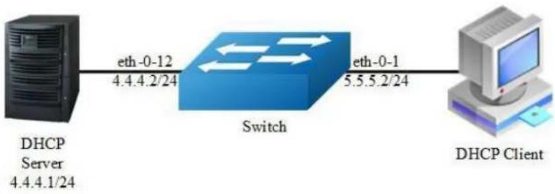
flowchart
graph LR
A["DHCP Server 4.4.4.1/24"] -->|eth-0-12 4.4.4.2/24| B["Switch"]
B -->|eth-0-1 5.5.5.2/24| C["DHCP Client"]
Figure 4-5 DHCP relay
This figure is the networking topology for testing DHCP relay functions. We need two Linux boxes and one Switch to construct the test bed.
Computer A is used as DHCP server.
Computer B is used as DHCP client.
Switch is used as DHCP relay agent.
step 1 Enter the configure mode
Switch# configure terminal
step 2 Enter the interface configure mode, set the attributes and ip address
Switch(config)# interface eth-0-12
Switch(config-if)# no switchport
Switch(config-if)# ip address 4.4.4.2/24
Switch(config-if)# no shutdown
Switch(config-if)# exit
Switch(config)# interface eth-0-1
Switch(config-if)# no switchport
Switch(config-if)# ip address 5.5.5.2/24
Switch(config-if)# no shutdown
Switch(config-if)# exit
step 3 Create a dhcp server
Switch(config)# dhcp-server 1 4.4.4.1
step 4 Enable DHCP server and option82 for the interface
Switch(config)# interface eth-0-1
Switch(config-if)# dhcp relay information trusted
Switch(config-if)# dhcp-server 1
Switch(config-if)# exit
step 5 Enable DHCP server and DHCP relay globally
Switch(config)# service dhcp enable
Switch(config)# dhcp relay
step 6 Validation
Check the interface configuration
Switch# show running-config interface eth-0-12
!
interface eth-0-12
no switchport
ip address 4.4.4.2/24
!
Switch# show running-config interface eth-0-1
!
interface eth-0-1
no switchport
dhcp relay information trusted
dhcp-server 1
ip address 5.5.5.2/24
!
Check the dhcp service status
Switch# show services
Networking services configuration:
Service Name Status
dhcp enable
Check the dhcp server group configuration
Switch# show dhcp-server
DHCP server group information:
group 1 ip address list:
[1] 4.4.4.1
Check the dhcp relay statistics
Switch# show dhcp relay statistics
DHCP relay packet statistics:
Client relayed packets: 20
Server relayed packets: 20
Client error packets: 20
Server error packets: 0
Bogus GIADDR drops: 0
Bad circuit ID packets: 0
Corrupted agent options: 0
Missing agent options: 0
Missing circuit IDs: 0
Check your computer ip address from DHCP server
Ipconfig /all
Dhcp Enabled. . . . . . . . . . : Yes
Autoconfiguration Enabled. . . . : Yes
IP Address. . . . . . . . . . . : 5.5.5.1
Subnet Mask. . . . . . . . . . . : 255.255.255.0
Default Gateway. . . . . . . . . : 5.5.5.2
DHCP Server. . . . . . . . . . : 4.4.4.1
DNS Servers. . . . . . . . . . : 4.4.4.1
4.4.3 Application cases
N/A
4.5 Configuring DHCP server
4.5.1 Overview
Function Introduction
A DHCP server is an Internet host that returns configuration parameters to DHCP clients. DHCP server can provide IP address and network configuration for DHCP client by DHCP. For provide DHCP service, DHCP server need to be configured first. For example, IP address pool need be create, default gateway should be set in a pool, and some network parameters for DHCP client should be set before DHCP working. After DHCP server start to work, it will find a valid IP address from pool for DHCP client when receiving client's request. Meantime it also send network configuration parameters to client. The IP address assigned by DHCP server have a period of validity(lease), so DHCP client need to renew its lease before the lease expired for reserving current IP address by sending DHCP REQUEST message.
If DHCP server was in the same subnet with client, it can normal work after connect to subnet. Otherwise DHCP relay was needed for server providing DHCP service, which can help to forward DHCP message between server and client.
Main options supported by DHCP server include bootfile-name, dns-server, domain-name, gateway, netbios-name-server, netbios-node-type, tftp-server-address. Besides these, some raw options were also be supported, which were set with option code.
Principle Description
N/A
4.5.2 Configuration
Configuring DHCP server
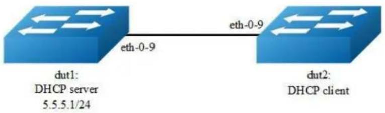
flowchart
graph LR
A["DHCP server 5.5.5.1/24"] -->|eth-0-9| B["DHCP client"]
B -->|eth-0-9| A
Figure 4-6 DHCP server
step 1 Enter the configure mode
Switch# configure terminal
step 2 Enable DHCP server globally, configure the ip address pool
Configure on DUT1:
Switch(config)#service dhcp enable
Switch(config)#dhcp server
Switch(config)#dhcp pool pool5
Switch(dhcp-config)#network 5.5.5.0/24
Switch(dhcp-config)#gateway 5.5.5.1
Switch(dhcp-config)#exit
step 3 Enter the interface configure mode, set the attributes and ip address
Configure on DUT1:
Switch(config)#interface eth-0-9
Switch (config-if)#no switchport
Switch (config-if)# no shutdown
Switch (config-if)# ip address 5.5.5.1/24
Switch (config-if)# dhcp server enable
Switch (config-if)#exit
Configure on DUT2:
Switch#configure terminal
Switch(config)#interface eth-0-9
Switch (config-if)#no switchport
Switch (config-if)# no shutdown
Switch (config-if)# ip address dhcp
Switch (config-if)#exit
step 4 Validation
Check DHCP Server(dut1) configuration:
Switch# show running-config
!
service dhcp enable
!
interface eth-0-9
no switchport
dhcp server enable
ip address 5.5.5.1/24!
!
dhcp server
dhcp pool pool5
network 5.5.5.0/24
gateway 5.5.5.1
Check DHCP client status on DHCP Server(dut1):
Switch# show dhcp client verbose
DHCP client informations:
------------------------
eth-0-9 DHCP client information:
Current state: BOUND
Allocated IP: 5.5.5.2 255.255.255.0
Lease/renewal/rebinding: 1194/546/1044 seconds
Lease from 2012-02-04 07:40:12 to 2012-02-04 08:00:12
Will Renewal in 0 days 0 hours 9 minutes 6 seconds
DHCP server: 5.5.5.1
Transaction ID: 0x45b0b27b
Default router: 5.5.5.1
Classless static route:
Destination: 5.5.4.0, mask: 255.255.255.0, Nexthop: 5.5.5.1
TFTP server addresses: 5.5.5.3
Client ID: switch-6e6e.361f.8400-eth-0-9
Check DHCP server statistics on DHCP Server(dut1):
Switch# show dhcp server statistics
DHCP server packet statistics:
Message Received:
BOOTREQUEST: 0
DHCPDISCOVER: 1
DHCPREQUEST: 1
DHCPDECLINE: 0
DHCPRELEASE: 0
DHCPINFORM: 0
Message Sent:
BOOTREPLY: 0
DHCPOFFER: 1
DHCPACK: 1
DHCPNAK: 0
Check DHCP server addresses and interfaces on DHCP Server(dut1):
Switch# show dhcp server binding all
IP address Client-ID/ Lease expiration Type
Hardware address
5.5.5.2 6e:6e:36:1f:84:00 Sat 2012.02.04 08:00:12 Dynamic
Switch# show dhcp server interfaces
List of DHCP server enabled interface(s):
DHCP server service status: enabled
Interface Name
------------------------
eth-0-9
Configuring DHCP server with relay
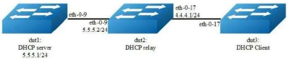
flowchart
graph LR
A["DHCP server 5.5.5.1/24"] -->|eth-0-9 5.5.5.2/24| B["DHCP relay"]
B -->|eth-0-17 4.4.4.1/24| C["DHCP Client"]
Figure 4-7 DHCP relay
step 1 Enter the configure mode
Switch# configure terminal
step 2 Enable DHCP server globally, configure the ip address pool and DHCP relay
Configure on DUT1:
Switch(config)#service dhcp enable
Switch(config)#dhcp server
Switch(dhcp-config)#dhcp pool pool4
Switch(dhcp-config)#network 4.4.4.0/24
Switch(dhcp-config)#gateway 4.4.4.1
Switch(dhcp-config)#exit
Configure on DUT2:
Switch(config)#service dhcp enable
Switch(config)#dhcp relay
Switch(config)#dhcp-server 1 5.5.5.1
step 2 Add a ip route
Configure on DUT1:
Switch(config)#ip route 4.4.4.0/24 5.5.5.2
step 4 Enter the interface configure mode, set the attributes and ip address
Configure on DUT1:
Switch(config)#interface eth-0-9
Switch (config-if)#no switchport
Switch (config-if)# no shutdown
Switch (config-if)# ip address 5.5.5.1/24
Switch (config-if)# dhcp server enable
Switch (config-if)#exit
Configure on DUT2:
Switch(config)#interface eth-0-17
Switch (config-if)#no switchport
Switch (config-if)# no shutdown
Switch (config-if)# ip address 4.4.4.1/24
Switch (config-if)# dhcp-server 1
Switch (config-if)#interface eth-0-9
Switch (config-if)#no switchport
Switch (config-if)# no shutdown
Switch (config-if)# ip address 5.5.5.2/24
Switch (config-if)#exit
Configure on DUT3:
Switch(config)#interface eth-0-17
Switch (config-if)#no switchport
Switch (config-if)# no shutdown
Switch (config-if)# ip address dhcp
Switch (config-if)#exit
step 5 Exit the configure mode
Switch(config)# end
step 6 Validation
Check DHCP Server(dut1) configuration:
Switch# show running-config
!
service dhcp enable
!
interface eth-0-9
no switchport
dhcp server enable
ip address 5.5.5.1/24!
ip route 4.4.4.0/24 5.5.5.2
!
dhcp server
dhcp pool pool4
network 4.4.4.0/24
gateway 4.4.4.1
Check DHCP client status on DHCP Server(dut1):
Switch# show dhcp client verbose
DHCP client informations:
------------------------
eth-0-17 DHCP client information:
Current state: BOUND
Allocated IP: 4.4.4.5 255.255.255.0
Lease/renewal/rebinding: 1199/517/1049 seconds
Lease from 2012-02-06 05:23:09 to 2012-02-06 05:43:09
Will Renewal in 0 days 0 hours 8 minutes 37 seconds
DHCP server: 5.5.5.1
Transaction ID: 0x192a4f7d
Default router: 4.4.4.1
Classless static route:
Destination: 5.5.4.0, mask: 255.255.255.0, Nexthop: 4.4.4.1
TFTP server addresses: 5.5.5.3
Client ID: switch-3c9a.b29a.ba00-cth-0-17
Check DHCP server statistics on DHCP Server(dut1):
Switch# show dhcp server statistics
DHCP server packet statistics:
Message Received:
BOOTREQUEST: 0
DHCPDISCOVER: 1
DHCPREQUEST: 1
DHCPDECLINE: 0
DHCPRELEASE: 0
DHCPINFORM: 0
Message Sent:
BOOTREPLY: 0
DHCPOFFER: 1
DHCPACK: 1
DHCPNAK: 0
Check DHCP server addresses and interfaces on DHCP Server(dut1):
Switch# show dhcp server binding all
IP address Client-ID/ Lease expiration Type
Hardware address
4.4.4.5 3c:9a:b2:9a:ba:00 Mon 2012.02.06 05:43:09 Dynamic
Switch# show dhcp server interfaces
List of DHCP server enabled interface(s):
DHCP server service status: enabled
Interface Name
eth-0-9
4.5.3 Application cases
N/A
4.6 Configuring DNS
4.6.1 Overview
Function Introduction
The DNS protocol controls the Domain Name System (DNS), a distributed database with which you can map hostnames to IP addresses. When you configure DNS on your switch, you can substitute the hostname for the IP address with all IP commands, such as ping, telnet, connect, and related Telnet support operations. IP defines a hierarchical naming scheme that allows a device to be identified by its location or domain. Domain names are pieced together with periods (.) as the delimiting characters. To keep track of domain names, IP has defined the concept of a domain name server, which holds a cache (or database) of names mapped to IP addresses. To map domain names to IP addresses, you must first identify the hostnames, specify the name server that is present on your network, and enable the DNS.
Principle Description
N/A
4.6.2 Configuration
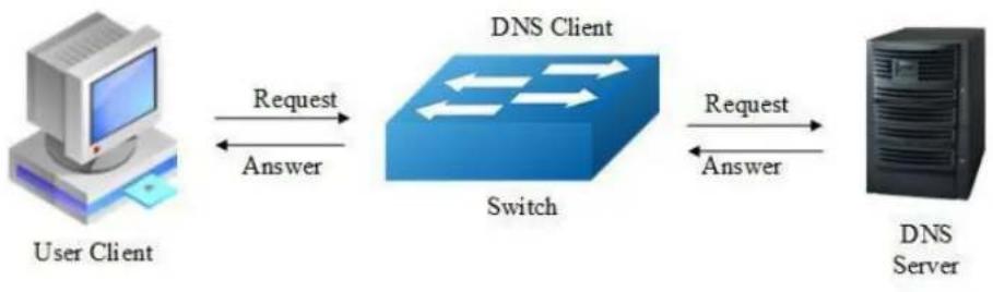
flowchart
graph LR
A["User Client"] -->|Request Answer| B["Switch"]
B -->|Request Answer| C["DNS Server"]
Figure 4-8 DNS
step 1 Enter the configure mode
Switch# configure terminal
step 2 Set the dns domain name and dns server address
Switch(config)#dns domain server1
Switch(config)#dns server 202.100.10.20
step 3 Set static hostname-to-address mappings (optional)
Switch(config)# ip host www.example1.com 192.0.2.141
step 4 Validation
Switch# show dns server
Current DNS name server configuration:
Server IP Address
5.1 Configuring IP Unicast-Routing
5.1.1 Overview
Function Introduction
Static routing is a concept describing one way of configuring path selection of routers in computer networks. It is the type of routing characterized by the absence of communication between routers regarding the current topology of the network. This is achieved by manually adding routes to the routing table. The opposite of static routing is dynamic routing, sometimes also referred to as adaptive routing.
In these systems, routes through a data network are described by fixed paths (statically). These routes are usually entered into the router by the system administrator. An entire network can be configured using static routes, but this type of configuration is not fault tolerant. When there is a change in the network or a failure occurs between two statically defined nodes, traffic will not be rerouted. This means that anything that wishes to take an affected path will either have to wait for the failure to be repaired or the static route to be updated by the administrator before restarting its journey. Most requests will time out (ultimately failing) before these repairs can be made. There are, however, times when static routes can improve the performance of a network. Some of these include stub networks and default routes.
Principle Description
N/A
5.1.2 Configuration

flowchart
graph LR
A["Switch1 192.168.0.1/32"] -->|cth-0-9 10.10.10.0/24 eth-0-9| B["Switch2 192.168.0.2/32"]
B -->|cth-0-17 10.10.12.0/24 cth-0-17| C["Switch3 192.168.0.3/32"]
Figure 5-1 ip unicast routing
This example shows how to enable static route in a simple network topology.
There are 3 static routes on Switch1, one is to achieve remote network 10.10.12.0/24, the other two are to achieve the loopback addresses on Switch2 and Switch3. There is a default static route on Switch3, that is, static routes use same gateway or nexthop address. There are 2 static routes on swithc2, both of them are to achieve the remote switch's loopback address.
step 1 Enter the configure mode
Switch# configure terminal
step 2 Enter the interface configure mode, set the attributes and ip address
Configure on Switch1:
Switch(config)# interface eth-0-9
Switch(config-if)# no shutdown
Switch(config-if)# no switchport
Switch(config-if)# ip address 10.10.10.1/24
Switch(config-if)# exit
Switch(config)# interface loopback 0
Switch(config-if)# ip address 192.168.0.1/32
Switch(config-if)# exit
Configure on Switch2:
Switch(config)# interface eth-0-9
Switch(config-if)# no shutdown
Switch(config-if)# no switchport
Switch(config-if)# ip address 10.10.10.2/24
Switch(config-if)# exit
Switch(config)# interface eth-0-17
Switch(config-if)# no shutdown
Switch(config-if)# no switchport
Switch(config-if)# ip address 10.10.12.2/24
Switch(config-if)# exit
Switch(config)# interface loopback 0
Switch(config-if)# ip address 192.168.0.2/32
Switch(config-if)# exit
Configure on Switch3:
Switch(config)# interface eth-0-17
Switch(config-if)# no shutdown
Switch(config-if)# no switchport
Switch(config-if)# ip address 10.10.12.3/24
Switch(config-if)# exit
Switch(config)# interface loopback 0
Switch(config-if)# ip add 192.168.0.3/32
Switch(config-if)# exit
step 3 Configuring static route
Configure on Switch1:
Note: Specify the destination prefix and mask for the network for which a gateway is required, for example, 10.10.12.0/24. Add a gateway for each of them (in this case 10.10.10.2 for all). Since R2 is the only next hop available, you can configure a default route instead of configuring the same static route for individual addresses.
Switch(config)# ip route 10.10.12.0/24 10.10.10.2
Switch(config)# ip route 192.168.0.2/32 10.10.10.2
Switch(config)# ip route 192.168.0.3/32 10.10.10.2
Configure on Switch2:
Switch(config)# ip route 192.168.0.1/32 10.10.10.1
Switch(config)# ip route 192.168.0.3/32 10.10.12.3
Configure on Switch3:
Note: Specify 10.10.12.2 as a default gateway to reach any network. Since 10.10.12.2 is the only route available you can specify it as the default gateway instead of specifying it as the gateway for individual network or host addresses.
Switch(config)# ip route 0.0.0.0/0 10.10.12.2
step 4 Exit the configure mode
Switch(config)# end
step 5 Validation
Use the following command to display the route information on Switch1:
Switch# show ip route
Codes: K - kernel, C - connected, S - static, R - RIP, B - BGP
O - OSPF, IA - OSPF inter area
N1 - OSPF NSSA external type 1, N2 - OSPF NSSA external type 2
E1 - OSPF external type 1, E2 - OSPF external type 2
i - IS-IS, L1 - IS-IS level-1, L2 - IS-IS level-2, ia - IS-IS inter area
[*] - [AD/Metric]
* - candidate default
C 10.10.10.0/24 is directly connected, eth-0-9
C 10.10.10.1/32 is in local loopback, eth-0-9
S 10.10.12.0/24 [1/0] via 10.10.10.2, eth-0-9
C 192.168.0.1/32 is directly connected, loopback0
S 192.168.0.2/32 [1/0] via 10.10.10.2, eth-0-9
S 192.168.0.3/32 [1/0] via 10.10.10.2, eth-0-9
Use the following command to display the route information on Switch2:
Switch# show ip route
Codes: K - kernel, C - connected, S - static, R - RIP, B - BGP
O - OSPF, IA - OSPF inter area
N1 - OSPF NSSA external type 1, N2 - OSPF NSSA external type 2
E1 - OSPF external type 1, E2 - OSPF external type 2
i - IS-IS, L1 - IS-IS level-1, L2 - IS-IS level-2, ia - IS-IS inter area
[*] - [AD/Metric]
* - candidate default
C 10.10.10.0/24 is directly connected, eth-0-9
C 10.10.10.2/32 is in local loopback, eth-0-9
C 10.10.12.0/24 is directly connected, eth-0-17
C 10.10.12.2/32 is in local loopback, eth-0-178 192.168.0.1/32 [1/0]
via 10.10.10.1, eth-0-9
C 192.168.0.2/32 is directly connected, loopback0
S 192.168.0.3/32 [1/0] via 10.10.12.3, eth-0-17
Use the following command to display the route information on Switch3:
Switch# show ip route
Codes: K - kernel, C - connected, S - static, R - RIP, B - BGP
O - OSPF, IA - OSPF inter area
N1 - OSPF NSSA external type 1, N2 - OSPF NSSA external type 2
E1 - OSPF external type 1, E2 - OSPF external type 2
i - IS-IS, L1 - IS-IS level-1, L2 - IS-IS level-2, ia - IS-IS inter area
[*] - [AD/Metric]
* - candidate default
Gateway of last resort is 10.10.12.2 to network 0.0.0.0
S* 0.0.0.0/0 [1/0] via 10.10.12.2, eth-0-17
C 10.10.12.0/24 is directly connected, eth-0-17
C 10.10.12.3/32 is in local loopback, eth-0-17
C 192.168.0.3/32 is directly connected, loopback0
5.1.3 Application cases
N/A
5.2 Configuring RIP
5.2.1 Overview
Function Introduction
Routing Information Protocol (RIP) is an IP route exchange protocol that uses a distance vector (a number representing distance) to measure the cost of a given route. The cost is a distance vector because the cost is often equivalent to the number of router hops between the source and the destination networks. RIP can receive multiple paths to a destination. The system evaluates the paths, selects the best path, and saves the path in the IP route table as the route to the destination. Typically, the best path is the path with the fewest hops. A hop is another router through which packets must travel to reach the destination. If RIP receives a RIP update from another router that contains a path with fewer hops than the path stored in the route table, the system replaces the older route with the newer one. The system then includes the new path in the updates it sends to other RIP routers. RIP routers also can modify a route's cost, generally by adding to it, to bias the selection of a route for a given destination. In this case, the actual number of router hops may be the same, but the route has an administratively higher cost and is thus less likely to be used than other, lower-cost routes. A RIP route can have a maximum cost of 15. Any destination with a higher cost is considered unreachable. Although limiting to larger networks, the low maximum hop count prevents endless loops in the network.
This chapter contains basic RIP configuration examples. To see details on the commands used in these examples, or to see the outputs of the Validation commands, refer to the RIP Command Reference. To avoid repetition, some Common commands, like configure terminal, have not been listed under the Commands Used section.
Principle Description
Reference to RFC 2453
5.2.2 Configuration
Enabling RIP

step 2 Enter the interface configure mode, set the attributes and ip address
Configure on Switch1:
Switch(config)# interface eth-0-1
Switch(config-if)# no switchport
Switch(config-if)# no shutdown
Switch(config-if)# ip address 10.10.10.10/24
Switch(config-if)# exit
Switch(config)# interface eth-0-9
Switch(config-if)# no switchport
Switch(config-if)# no shutdown
Switch(config-if)# ip address 10.10.11.10/24
Switch(config-if)# exit
Configure on Switch2:
Switch(config)# interface eth-0-1
Switch(config-if)# no switchport
Switch(config-if)# no shutdown
Switch(config-if)# ip address 10.10.12.10/24
Switch(config-if)# exit
Switch(config)# interface eth-0-9
Switch(config-if)# no switchport
Switch(config-if)# no shutdown
Switch(config-if)# ip address 10.10.11.50/24
Switch(config-if)# exit
step 3 Enable RIP routing process and associate networks
Configure on Switch1:
Switch(config)# router rip
Switch(config-router)#network 10.10.10.0/24
Switch(config-router)#network 10.10.11.0/24
Switch(config-router)# exit
Configure on Switch2:
Switch(config)# router rip
Switch(config-router)#network 10.10.11.0/24
Switch(config-router)#network 10.10.12.0/24
Switch(config-router)# exit
step 5 Exit the configure mode
Switch(config)# end
step 6 Validation
Use the following command to display the database of rip on Switch1:
Switch# show ip rip database
Codes: R - RIP, Rc - RIP connected, Rs - RIP static, K - Kernel,
C - Connected, S - Static, O - OSPF, I - IS-IS, B - BGP
Network Next Hop Metric From If Time
Rc 10.10.10.0/24 1 eth-0-1
Rc 10.10.11.0/24 1 eth-0-9
R 10.10.12.0/24 10.10.11.50 2 10.10.11.50 eth-0-9 00: 02: 52
Use the following command to display the protocol state of rip process on Switch1:
Switch# show ip protocols rip
Routing protocol is "rip"
Sending updates every 30 seconds with +/-5 seconds, next due in 17 seconds
Timeout after 180 seconds, Garbage collect after 120 seconds
Outgoing update filter list for all interface is not set
Incoming update filter list for all interface is not set
Default redistribution metric is 1
Redistributing:
Default version control: send version 2, receive version 2
Interface Send Recv Key-chain
eth-0-1 2 2
eth-0-9 2 2
Routing for Networks:
10.10.10.0/24
10.10.11.0/24
Routing Information Sources:
Gateway Distance Last Update Bad Packets Bad Routes
10.10.11.50 120 00:00:22 0 0
Number of routes (including connected): 3
Distance: (default is 120)
Use the following command to display the interface of rip on Switch1:
Switch# show ip rip interface
eth-0-1 is up, line protocol is up
Routing Protocol: RIP
Receive RIP packets
Send RIP packets
Passive interface: Disabled
Split horizon: Enabled with Poisoned Reversed
IP interface address:
10.10.10.10/24
eth-0-9 is up, line protocol is up
Routing Protocol: RIP
Receive RIP packets
Send RIP packets
Passive interface: Disabled
Split horizon: Enabled with Poisoned Reversed
IP interface address:
10.10.11.10/24
Use the following command to display routes on Switch1:
Switch# show ip route
Codes: K - kernel, C - connected, S - static, R - RIP, B - BGP
O - OSPF, IA - OSPF inter area
N1 - OSPF NSSA external type 1, N2 - OSPF NSSA external type 2
E1 - OSPF external type 1, E2 - OSPF external type 2
i - IS-IS, L1 - IS-IS level-1, L2 - IS-IS level-2, ia - IS-IS inter area
[*] - [AD/Metric]
* - candidate default
C 10.10.10.0/24 is directly connected, eth-0-1
C 10.10.10.10/32 is in local loopback, eth-0-1
C 10.10.11.0/24 is directly connected, eth-0-9
C 10.10.11.10/32 is in local loopback, eth-0-9
R 10.10.12.0/24 [120/2] via 10.10.11.50, eth-0-9, 00: 25: 50
Configuring The RIP Version

flowchart
graph LR
Switch1["Switch1"] -->|eth-0-9 10.10.11.10| Switch2["Switch2"]
Switch2 -->|eth-0-20 10.10.12.10| Switch3["Switch3"]
Switch2 -->|eth-0-20 10.10.12.50| Switch3
Figure 5-3 rip version
Configure the receive and send specific versions of packets on an interface.
In this example, Switch2 is configured to receive and send RIP version 1 and 2 on eth-0-9 and eth-0-20.
step 1 Enter the configure mode
The following commands operate on Switch2:
Switch# configure terminal
step 2 Enable RIP routing process
Switch(config)# router rip
Switch(config-router)# exit
step 3 Enter the interface configure mode and set the version for sending and receiving rip packets
Switch(config)# interface eth-0-9
Switch(config-if)# ip rip send version 1 2
Switch(config-if)# ip rip receive version 1 2
Switch(config-if)# quit
Switch(config)# interface eth-0-20
Switch(config-if)# ip rip send version 1 2
Switch(config-if)# ip rip receive version 1 2
Switch(config-if)# quit
step 4 Exit the configure mode
Switch(config)# end
step 5 Validation
Use the following command to display the configuration on Switch1:
Switch# show running-config
interface eth-0-9
no switchport
ip address 10.10.11.10/24
!
router rip
network 10.10.11.0/24
Use the following command to display the database of rip on Switch2:
Switch# show ip rip database
Codes: R - RIP, Rc - RIP connected, Rs - RIP static, K - Kernel,
C - Connected, S - Static, O - OSPF, I - IS-IS, B - BGP
Network Next Hop Metric From If Time
R 10.0.0.0/8 1 eth-0-9
Rc 10.10.11.0/24 1 eth-0-9
Rc 10.10.12.0/24 1 eth-0-20
Use the following command to display the protocol state of rip process on Switch2:
Switch# show ip protocols rip
Routing protocol is "rip"
Sending updates every 30 seconds with +/-5 seconds, next due in 1 seconds
Timeout after 180 seconds, Garbage collect after 120 seconds
Outgoing update filter list for all interface is not set
Incoming update filter list for all interface is not set
Default redistribution metric is 1
Redistributing:
Default version control: send version 2, receive version 2
Interface Send Recv Key-chain
cth-0-9 1 2 1 2
eth-0-20 1 2 1 2
Routing for Networks:
10.10.11.0/24
10.10.12.0/24
Routing Information Sources
Gateway Distance Last Update Bad Packets Bad Routes
10.10.11.10 120 00: 00: 22 0 0
10.10.12.50 120 00: 00: 27 0 0
Number of routes (including connected): 3 Distance
: (default is 120)
Use the following command to display the interface of rip on Switch2:
Switch# show ip rip interface
eth-0-9 is up, line protocol is up
Routing Protocol: RIP
Receive RIPv1 and RIPv2 packets
Send RIPv1 and RIPv2 packets
Passive interface: Disabled
Split horizon: Enabled with Poisoned Reversed
IP interface address:
10.10.11.50/24
eth-0-20 is up, line protocol is up
Routing Protocol: RIP
Receive RIPv1 and RIPv2 packets
Send RIPv1 and RIPv2 packets
Passive interface: Disabled
Split horizon: Enabled with Poisoned Reversed
IP interface address:
10.10.12.10/24
Use the following command to display the configuration on Switch2:
Switch# show run
interface eth-0-9
no switchport
ip address 10.10.11.50/24
ip rip send version 1 2
ip rip receive version 1 2
!
interface eth-0-20
no switchport
ip address 10.10.12.10/24
ip rip send version 1 2
ip rip receive version 1 2
!
router rip
network 10.10.11.0/24
network 10.10.12.0/24
Use the following command to display the configuration on Switch3:
Switch# show running-config
interface eth-0-20
no switchport
ip address 10.10.12.50/24
!
router rip
network 10.10.12.0/24
Configuring Metric Parameters
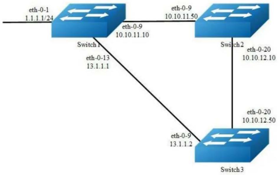
flowchart
graph TD
A["eth-0-1\n1.1.1.1/24"] -->|eth-0-9\n10.10.11.10| B["Switch 1"]
B -->|eth-0-13\n13.1.1.1| C["Switch 2"]
C -->|eth-0-20\n10.10.12.10| D["Switch 3"]
D -->|eth-0-20\n10.10.12.50| E["Switch 3"]
E -->|eth-0-9\n13.1.1.2| F["Switch 3"]
F -->|eth-0-9\n10.10.11.50| G["Switch 2"]
Figure 5-4 rip metric
A RIP offset list allows you to add to the metric of specific inbound or outbound routes learned or advertised by RIP. RIP offset lists provide a simple method for adding to the cost of specific routes and therefore biasing the router's route selection away from those routes. An offset list consists of the following parameters:
An ACL that specifies the routes to which to add the metric. The direction:
In: applies to routes the router learns from RIP neighbors.
Out: applies to routes the router is advertising to its RIP neighbors.
The offset value that will be added to the routing metric of the routes that match the ACL.
The interface that the offset list applies (optional).
If a route matches both a global offset list (without specified interface) and an interface-based offset list, the interface-based offset list takes precedence. The interface-based offset list's metric is added to the route in this case.
This example Switch1 will advertise route 1.1.1.0 out of int eth-0-13 with metric 3.
step 1 precondition
Switch1
interface eth-0-1
no switchport
ip address 1.1.1.1/24
!
interface eth-0-9
no switchport
ip address 10.10.11.10/24
!
interface eth-0-13
no switchport
ip address 13.1.1.1/24
!
router rip
network 1.1.1.0/24
network 10.10.11.0/24
network 13.1.1.0/24
Switch2
interface eth-0-9
no switchport
ip address 10.10.11.50/24
!
interface eth-0-20
no switchport
ip address 10.10.12.10/24
!
router rip
network 10.10.11.0/24
network 10.10.12.0/24
Switch3
interface eth-0-13
no switchport
ip address 13.1.1.2/24
!
interface eth-0-20
no switchport
ip address 10.10.12.50/24
!
router rip
network 10.10.12.0/24
network 13.1.1.0/24
Display the routes on Switch3:
Switch# show ip route rip
R 1.1.1.0/24 [120/2] via 13.1.1.1, eth-0-13, 00: 07: 46
R 10.10.11.0/24 [120/2] via 13.1.1.1, eth-0-13, 00: 07: 39
[120/2] via 10.10.12.10, eth-0-20, 00: 07: 39
Change router 1.1.1.0/24 via 10.10.12.10
step 2 Enter the configure mode
The following commands operate on Switch1:
Switch# configure terminal
step 3 Configuring access list
Switch(config)#ip access-list ripoffset
Switch(config-ip-acl)#permit any 1.1.1.0 0.0.0.255 any
step 4 Enable RIP routing process and set offset list and offset value for an interface
Switch(config-ip-acl)# router rip
Switch(config-router)# offset-list ripoffset out 3 eth-0-13
step 5 Exit the configure mode
Switch(config-router)# end
step 6 Validation
Display the routes on Switch3. The metric for the route which distributed by Switch1 is 3 now.
Switch# show ip route rip
R 1.1.1.0/24 [120/3] via 10.10.12.10, eth-0-20, 00: 00: 02
R 10.10.11.0/24 [120/2] via 13.1.1.1, eth-0-13, 00: 11: 40
[120/2] via 10.10.12.10, eth-0-20, 00: 11: 40
Configuring the Administrative Distance

Figure 5-5 rip distance
By default, RIP assigns the default RIP administrative distance (120) to RIP routes. When comparing routes based on administrative distance, the router selects the route with the lower distance. You can change the administrative distance for RIP routes.
This example all Switches have two router protocols, RIP and OSPF, OSPF route has higher priority, Switch3 will change route 1.1.1.0 with administrative distance 100.
step 1 precondition
Switch1
interface eth-0-1
no switchport
ip address 1.1.1.1/24
!
interface eth-0-9
no switchport
ip address 10.10.11.10/24
!
router ospf
network 1.1.1.0/24 area 0
network 10.10.11.0/24 area 0
!
router rip
network 1.1.1.0/24
network 10.10.11.0/24
Switch2
interface eth-0-9
no switchport
ip address 10.10.11.50/24
!
interface eth-0-20
no switchport
ip address 10.10.12.10/24
!
router ospf
network 10.10.11.0/24 area 0
network 10.10.12.0/24 area 0
!
router rip
network 10.10.11.0/24
network 10.10.12.0/24
Switch3
interface eth-0-20
no switchport
ip address 10.10.12.50/24
!
router ospf
network 10.10.12.0/24 area 0
!
router rip
network 10.10.12.0/24
Display the routes on Switch3:
Switch# show ip route
Codes: K - kernel, C - connected, S - static, R - RIP, B - BGP
O - OSPF, IA - OSPF inter area
N1 - OSPF NSSA external type 1, N2 - OSPF NSSA external type 2
E1 - OSPF external type 1, E2 - OSPF external type 2
i - IS-IS, L1 - IS-IS level-1, L2 - IS-IS level-2, ia - IS-IS inter area
[*] - [AD/Metric]
* - candidate default
O 1.1.1.0/24 [110/3] via 10.10.12.10, eth-0-20, 01: 05: 49
O 10.10.11.0/24 [110/2] via 10.10.12.10, eth-0-20, 01: 05: 49
C 10.10.12.0/24 is directly connected, eth-0-20
C 10.10.12.50/32 is in local loopback, eth-0-20
step 2 Enter the configure mode
The following commands operate on Switch3:
Switch# configure terminal
step 3 Configuring access list
Switch(config)#ip access-list ripdistancelist
Switch(config-ip-acl)#permit any 1.1.1.0 0.0.0.255 any
step 4 Enable RIP routing process and set administrative distance
Switch(config-ip-acl)# router rip
Switch(config-router)# distance 100 0.0.0.0/0 ripdistancelist
step 5 Exit the configure mode
Switch(config-router)# end
step 6 Validation
Display the routes on Switch3. The distance for the rip route is 100 now.
Switch# show ip route
Codes: K - kernel, C - connected, S - static, R - RIP, B - BGP
O - OSPF, IA - OSPF inter area
N1 - OSPF NSSA external type 1, N2 - OSPF NSSA external type 2
E1 - OSPF external type 1, E2 - OSPF external type 2
i - IS-IS, L1 - IS-IS level-1, L2 - IS-IS level-2, ia - IS-IS inter area
[*] - [AD/Metric]
* - candidate default
R 1.1.1.0/24 [100/3] via 10.10.12.10, eth-0-20, 00: 00: 02
O 10.10.11.0/24 [110/2] via 10.10.12.10, eth-0-20, 01: 10: 42
C 10.10.12.0/24 is directly connected, eth-0-20
C 10.10.12.50/32 is in local loopback, eth-0-20
Configuring Redistribution
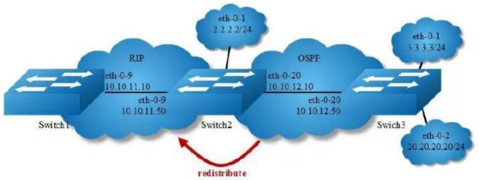
flowchart
graph LR
A["Switch1"] --> B["RIP"]
B --> C["Switch2"]
C --> D["OSPF"]
D --> E["Switch3"]
E --> F["eth-0-1 2.2.2/24"]
B --> G["eth-0-9 10.10.11.10"]
B --> H["eth-0-9 10.10.11.50"]
D --> I["eth-0-20 10.10.12.10"]
D --> J["eth-0-20 10.10.12.50"]
E --> K["eth-0-2 20.20.20/24"]
style A fill:#f9f,stroke:#333
style B fill:#ccf,stroke:#333
style C fill:#cfc,stroke:#333
style D fill:#fcc,stroke:#333
style E fill:#cff,stroke:#333
style F fill:#ffc,stroke:#333
style G fill:#cfc,stroke:#333
style H fill:#cfc,stroke:#333
style I fill:#cfc,stroke:#333
style J fill:#cfc,stroke:#333
style K fill:#cfc,stroke:#333
note right of C "redistribute"
Figure 5-6 rip redistribute
You can configure the router to redistribute static routes, direct connected routes or routes learned through Open Shortest Path First (OSPF) into RIP. When you redistribute a route from one of these other protocols into RIP, the router can use RIP to advertise the route to its RIP neighbors.
Change the default redistribution metric (optional). The router assigns a RIP metric of 1 to each redistributed route by default. You can change the default metric to a value up to 16.
Enable specified routes to redistribute with default or specified metric. This example the router will set the default metric to 2 for redistributed routes and redistributes static routes and direct connected routes to RIP with default metric 2, redistributes OSPF routes with specified metric 5.
step 1 precondition
Switch1
interface eth-0-9
no switchport
ip address 10.10.11.10/24
!
router rip
network 10.10.11.0/24
Switch2
interface eth-0-1
no switchport
ip address 2.2.2.2/24
!
interface eth-0-9
no switchport
ip address 10.10.11.50/24
!
interface eth-0-20
no switchport
ip address 10.10.12.10/24
!
router ospf
network 10.10.12.0/24 area 0
!
router rip
network 10.10.11.0/24
!
ip route 20.20.20.0/24 10.10.12.50
Switch3
interface eth-0-1
no switchport
ip address 3.3.3.3/24
!
interface eth-0-2
no switchport
ip address 20.20.20.20/24
!
interface eth-0-20
no switchport
ip address 10.10.12.50/24
!
router ospf
network 3.3.3.0/24 area 0
network 10.10.12.0/24 area 0
Display the routes on Switch1:
Switch# show ip route
Codes: K - kernel, C - connected, S - static, R - RIP, B - BGP
O - OSPF, IA - OSPF inter area
N1 - OSPF NSSA external type 1, N2 - OSPF NSSA external type 2
E1 - OSPF external type 1, E2 - OSPF external type 2
i - IS-IS, L1 - IS-IS level-1, L2 - IS-IS level-2, ia - IS-IS inter area [*] - [AD/Metric]
* - candidate default
C 10.10.11.0/24 is directly connected, eth-0-9
C 10.10.11.10/32 is in local loopback, eth-0-9
Display the routes on Switch2:
Switch# show ip route
Codes: K - kernel, C - connected, S - static, R - RIP, B - BGP
O - OSPF, IA - OSPF inter area
N1 - OSPF NSSA external type 1, N2 - OSPF NSSA external type 2
E1 - OSPF external type 1, E2 - OSPF external type 2
i - IS-IS, L1 - IS-IS level-1, L2 - IS-IS level-2, ia - IS-IS inter area
[*] - [AD/Metric]
* - candidate default
C 2.2.2.0/24 is directly connected, eth-0-1
C 2.2.2.02/32 is in local loopback, eth-0-1
O 3.3.3.0/24 [110/2] via 10.10.12.50, eth-0-20, 01: 05: 41
C 10.10.11.0/24 is directly connected, eth-0-9
C 10.10.11.50/32 is in local loopback, eth-0-9
C 10.10.12.0/24 is directly connected, eth-0-20
C 10.10.12.10/24 is in local loopback, eth-0-20
S 20.20.20.0/24 [1/0] via 10.10.12.50, eth-0-20
step 2 Enter the configure mode
The following commands operate on Switch2:
Switch# configure terminal
step 3 Enable RIP routing process and set metric and enable redistribute
Switch(config)# router rip
Switch(config-router)# default-metric 2
Switch(config-router)# redistribute static
Switch(config-router)# redistribute connected
Switch(config-router)# redistribute ospf metric 5
redistribute connected routes by ospf (optional)
Switch(config)# router ospf
Switch(config-router)# redistribute connected
step 4 Exit the configure mode
Switch(config-router)# end
step 5 Validation
Display the routes on Switch1:
Switch# show ip route
Codes: K - kernel, C - connected, S - static, R - RIP, B - BGP
O - OSPF, IA - OSPF inter area
N1 - OSPF NSSA external type 1, N2 - OSPF NSSA external type 2
E1 - OSPF external type 1, E2 - OSPF external type 2
i - IS-IS, L1 - IS-IS level-1, L2 - IS-IS level-2, ia - IS-IS inter area
[*] - [AD/Metric]
* - candidate default
R 2.2.2.0/24 [120/3] via 10.10.11.50, eth-0-9, 00: 02: 36
R 3.3.3.0/24 [120/6] via 10.10.11.50, eth-0-9, 00: 02: 26
C 10.10.11.0/24 is directly connected, eth-0-9
C 10.10.11.10/32 is in local loopback eth-0-9
R 10.10.12.0/24 [120/3] via 10.10.11.50, eth-0-9, 00: 02: 36
R 20.20.20.0/24 [120/3] via 10.10.11.50, eth-0-9, 00: 02: 41
Configuring Split-horizon Parameters
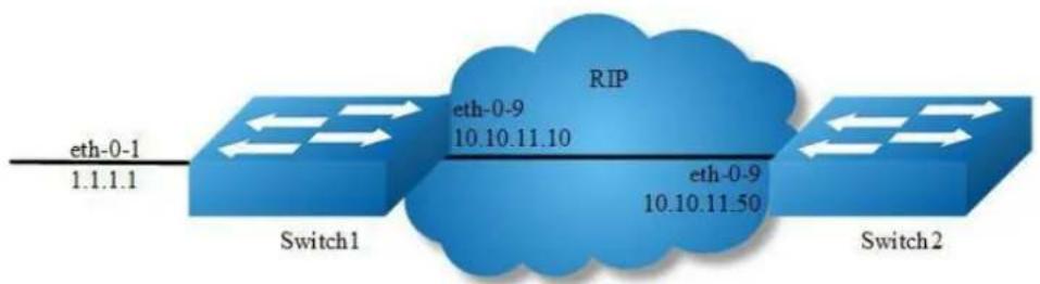
flowchart
graph LR
A["eth-0-1 1.1.1.1"] --> B["Switch1"]
B --> C["RIP"]
C --> D["eth-0-9 10.10.11.10"]
C --> E["eth-0-9 10.10.11.50"]
F["Switch2"] --> G["eth-0-9 10.10.11.50"]
Figure 5-7 rip split-horizon
Normally, routers that are connected to broadcast-type IP networks and that use distance-vector routing protocols employ the split horizon mechanism to reduce the possibility of routing loops. Split horizon blocks information about routes from being advertised by a router out of any interface from which that information originated. This behavior usually optimizes communications among multiple routers, particularly when links are broken. However, with non-broadcast networks (such as Frame Relay), situations can arise for which this behavior is less than ideal. For these situations, you might want to disable split horizon for RIP.
You can avoid including routes in updates sent to the same gateway from which they were learned. Using the split horizon command omits routes learned from one neighbor, in updates sent to that neighbor. Using the poisoned parameter with this command includes such routes in updates, but sets their metrics to infinity. Thus, advertising these routes means that they are not reachable.
step 1 precondition
Switch1
interface eth-0-1
no switchport
ip address 1.1.1.1/24
!
interface eth-0-9
no switchport
ip address 10.10.11.10/24
!
router rip
network 10.10.11.0/24
redistribute connected
Switch2
interface eth-0-9
no switchport
ip address 10.10.11.50/24
!
router rip
network 10.10.11.0/24
step 2 Enabling debug on Switch2 (optional)
Switch# debug rip packet send detail
Switch# terminal monitor
step 3 Enter the configure mode
The following commands operate on Switch2:
Switch# configure terminal
step 4 Enter the interface configure mode and set split-horizon
Disable Split-horizon:
Switch(config)#interface eth-0-9
Switch(config-if)# no ip rip split-horizon
If debug is enabled, the following messages will be shown:
Apr 8 06: 24: 25 Switch RIP4-7: SEND[eth-0-9]: Send to 224.0.0.9: 520
Apr 8 06: 24: 25 Switch RIP4-7: SEND[eth-0-9]: RESPONSE version 2 packet size 44
Apr 8 06: 24: 25 Switch RIP4-7: 1.1.1.0/24 -> 0.0.0.0 family 2 tag 0 metric 2
Apr 8 06: 24: 25 Switch RIP4-7: 10.10.11.0/24 -> 0.0.0.0 family 2 tag 0 metric 1
Enable Split-horizon and poisoned:
Switch(config-if)# ip rip split-horizon
Switch(config-if)# ip rip split-horizon poisoned
If debug is enabled, the following messages will be shown:
Apr 8 06: 38: 35 Switch RIP4-7: SEND[eth-0-9]: Send to 224.0.0.9: 520
Apr 8 06: 38: 35 Switch RIP4-7: SEND[eth-0-9]: RESPONSE version 2 packet size 44
Apr 8 06: 38: 35 Switch RIP4-7: 1.1.1.0/24 -> 0.0.0.0 family 2 tag 0 metric 16
Apr 8 06: 38: 35 Switch RIP4-7: 10.10.11.0/24 -> 0.0.0.0 family 2 tag 0 metric 16
step 5 Exit the configure mode
Switch(config-router)# end
step 6 Validation
Use the following command to display the configuration:
Switch# show running-config
interface eth-0-9
no switchport
ip address 10.10.11.50/24
!
router rip
network 10.10.11.0/24
!
Use the following command to display the interface of rip:
Switch# show ip rip interface
eth-0-9 is up, line protocol is up
Routing Protocol: RIP
Receive RIP packets
Send RIP packets
Passive interface: Disabled
Split horizon: Enabled with Poisoned Reversed
IP interface address:
10.10.11.50/24
Configuring Timers
RIP use several timers that determine such variables as the frequency of routing updates, the length of time before a route becomes invalid, and other parameters.
You can adjust these timers to tune RIP performance to better suit your internetwork needs. You can make the following timer adjustments:
The rate (time in seconds between updates) at which routing updates are sent.
The interval of time (in seconds) after which a route is declared invalid.
The amount of time (in seconds) that must pass before a route is removed from the routing table.
step 1 Enter the configure mode
Switch# configure terminal
step 2 Enable RIP routing process and set the timers
Specify the routing table update timer in 10 seconds. Specifies the routing information timeout timer in 180 seconds. Specifies the routing garbage collection timer in 120 seconds:
Switch(config)# router rip
Switch(config-router)# timers basic 10 180 120
step 3 Exit the configure mode
Switch(config-router)# end
step 4 Validation
Use the following command to display the protocol state of rip process:
Switch# show ip protocols rip
Routing protocol is "rip"
Sending updates every 10 seconds with +/-5 seconds, next due in 2 seconds
Timeout after 180 seconds, Garbage collect after 120 seconds
Outgoing update filter list for all interface is not set
Incoming update filter list for all interface is not set
Default redistribution metric is 1
Redistributing:
Default version control: send version 2, receive version 2
Interface Send Recv Key-chain
eth-0-9 2 2
Routing for Networks:
10.10.11.0/24
Routing Information Sources:
Gateway Distance Last Update Bad Packets Bad Routes
10.10.11.50 120 00:00:02 0 0
Number of routes (including connected): 5
Distance: (default is 120)
Configuring RIP Route Distribute Filters
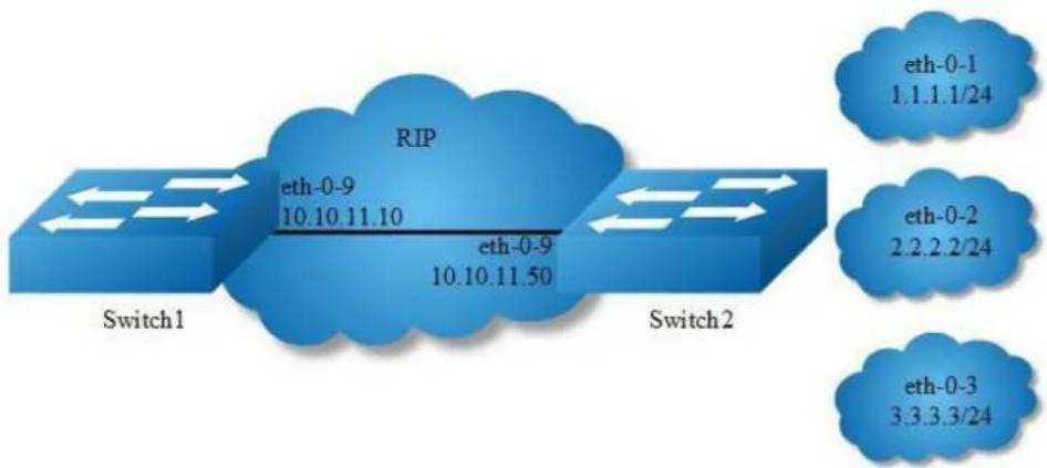
flowchart
graph LR
A["Switch1"] -->|eth-0-9 10.10.11.10| B["RIP"]
B -->|eth-0-9 10.10.11.50| C["Switch2"]
D["eth-0-1 1.1.1.1/24"] --> E
F["eth-0-2 2.2.2.2/24"] --> G
H["eth-0-3 3.3.3.3/24"] --> I
Figure 5-8 rip filter list
A RIP distribute list allows you to permit or deny learning or advertising of specific routes. A distribute list consists of the following parameters:
- An ACL or a prefix list that filter the routes.
- The direction:
Out: filter applies to advertised routes
- The interface that the filer applies (optional).
step 1 precondition
Switch1
interface eth-0-9
no switchport
ip address 10.10.11.10/24
!
router rip
network 10.10.11.0/24
Switch2
interface eth-0-1
no switchport
ip address 1.1.1.1/24
!
interface eth-0-2
no switchport
ip address 2.2.2.2/24
!
interface eth-0-3
no switchport
ip address 3.3.3.3/24
!
interface eth-0-9
no switchport
ip address 10.10.11.50/24
!
router rip
network 1.1.1.0/24
network 2.2.2.0/24
network 3.3.3.0/24
network 10.10.11.0/24
Display the routes on Switch1:
Switch# show ip route
Codes: K - kernel, C - connected, S - static, R - RIP, B - BGP
O - OSPF, IA - OSPF inter area
N1 - OSPF NSSA external type 1, N2 - OSPF NSSA external type 2
E1 - OSPF external type 1, E2 - OSPF external type 2
i - IS-IS, L1 - IS-IS level-1, L2 - IS-IS level-2, ia - IS-IS inter area
[*] - [AD/Metric]
* - candidate default
R 1.1.1.0/24 [120/2] via 10.10.11.50, eth-0-9, 00:01:50
R 2.2.2.0/24 [120/2] via 10.10.11.50, eth-0-9, 00:01:50
R 3.3.3.0/24 [120/2] via 10.10.11.50, eth-0-9, 00:01:50
C 10.10.11.0/24 is directly connected, eth-0-9
C 10.10.11.10/32 is in local loopback, eth-0-9
step 2 Enter the configure mode
The following commands operate on Switch2:
Switch# configure terminal
step 3 Configuring prefix list
Switch(config)# ip prefix-list 1 deny 1.1.1.0/24
Switch(config)# ip prefix-list 1 permit any
step 4 Apply prefix list
Switch(config)# router rip
Switch(config-router)# distribute-list prefix 1 out
step 5 Exit the configure mode
Switch(config-router)# end
step 6 Validation
Display the routes on Switch1:
Switch# show ip route
Codes: K - kernel, C - connected, S - static, R - RIP, B - BGP
O - OSPF, IA - OSPF inter area
N1 - OSPF NSSA external type 1, N2 - OSPF NSSA external type 2
E1 - OSPF external type 1, E2 - OSPF external type 2
i - IS-IS, L1 - IS-IS level-1, L2 - IS-IS level-2, ia - IS-IS inter area
[*] - [AD/Metric]
* - candidate default
R 2.2.2.0/24 [120/2] via 10.10.11.50, eth-0-9, 00:00:08
R 3.3.3.0/24 [120/2] via 10.10.11.50, eth-0-9, 00:00:08
C 10.10.11.0/24 is directly connected, eth-0-9
C 10.10.11.10/32 is in local loopback, eth-0-9
Configuring RIPv2 authentication (single key)
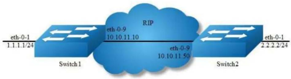
flowchart
graph LR
A["eth-0-1\n1.1.1.1/24"] --> B["Switch1"]
B --> C["RIP\neth-0-9\n10.10.11.10"]
C --> D["Switch2"]
D --> E["eth-0-1\n2.2.2.2/24"]
Figure 5-9 rip authentication
RIPv2 supports 2 authentication methods: plaintext and MD5 encryption.
The following example shows how to enable plaintext authentication.
To using this feature, the following steps are required:
Specify an interface and set the authentication string
Specify the authentication mode as "text"
step 1 Enter the configure mode
Switch# configure terminal
step 2 Enter the interface configure mode, set the attributes and ip address
Switch1:
Switch(config)# interface eth-0-1
Switch(config-if)# no switchport
Switch(config-if)# no shutdown
Switch(config-if)# ip address 1.1.1.1/24
Switch(config-if)# exit
Switch(config-if)# interface eth-0-9
Switch(config-if)# no switchport
Switch(config-if)# no shutdown
Switch(config-if)# ip address 10.10.11.10/24
Switch(config-if)# exit
Switch2:
Switch(config)# interface eth-0-1
Switch(config-if)# no switchport
Switch(config-if)# no shutdown
Switch(config-if)# ip address 2.2.2.2/24
Switch(config-if)# exit
Switch(config-if)# interface eth-0-9
Switch(config-if)# no switchport
Switch(config-if)# no shutdown
Switch(config-if)# ip address 10.10.11.50/24
Switch(config-if)# exit
step 3 Enable RIP routing process and set the parameters
Switch(config)# router rip
Switch(config-router)# network 10.10.11.0/24
Switch(config-router)# redistribute connected
Switch(config-router)# exit
step 4 Specify the authentication string and mode
Switch(config)# interface eth-0-9
Switch(config-if)# ip rip authentication string Auth1
Switch(config-if)# ip rip authentication mode text
step 5 Exit the configure mode
Switch(config-if)# end
step 6 Validation
Use the following command to display the database of rip:
Switch# show ip rip database
Codes: R - RIP, Rc - RIP connected, Rs - RIP static, K - Kernel,
C - Connected, S - Static, O - OSPF, I - IS-IS, B - BGP
Network Next Hop Metric From If Time
R 2.2.2.0/24 10.10.11.50 2 10.10.11.50 eth-0-9 00:02:52
Rc 10.10.11.0/24
Use the following command to display the protocol state of rip process:
Switch# show ip protocols rip
Routing protocol is "rip"
Sending updates every 30 seconds with +/-5 seconds, next due in 23 seconds
Timeout after 180 seconds, Garbage collect after 120 seconds
Outgoing update filter list for all interface is not set
Incoming update filter list for all interface is not set
Default redistribution metric is 1
Redistributing:
connected metric default
Default version control: send version 2, receive version 2
Interface Send Recv Key-chain
eth-0-9 2 2
Routing for Networks:
10.10.11.0/24
Routing Information Sources:
Gateway Distance Last Update Bad Packets Bad Routes
10.10.11.50 120 00:00:45 1 0
Number of routes (including connected): 2
Distance: (default is 120)
Switch# show ip rip interface
eth-0-9 is up, line protocol is up
Routing Protocol: RIP
Receive RIP packets
Send RIP packets
Passive interface: Disabled
Split horizon: Enabled with Poisoned Reversed
IP interface address:
10.10.11.10/24
Use the following command to display the interface of rip:
Switch# show ip route
Codes: K - kernel, C - connected, S - static, R - RIP, B - BGP
O - OSPF, IA - OSPF inter area
N1 - OSPF NSSA external type 1, N2 - OSPF NSSA external type 2
E1 - OSPF external type 1, E2 - OSPF external type 2
i - IS-IS, L1 - IS-IS level-1, L2 - IS-IS level-2, ia - IS-IS inter area
Dc - DHCP Client
[*] - [AD/Metric]
* - candidate default
R 2.2.2.0/24 [120/2] via 10.10.11.50, eth-0-9, 00:02:28
C 10.10.11.0/24 is directly connected, eth-0-9
C 10.10.11.10/32 is in local loopback, eth-0-9
Configuring RIPv2 MD5 authentication (multiple keys)
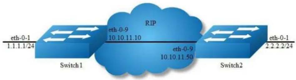
flowchart
graph LR
A["Switch 1"] -->|eth-0-9\n10.10.11.10| B["RIP"]
C["Switch 2"] -->|eth-0-9\n10.10.11.50| B
B -->|eth-0-1\n1.1.1.1/24| D["Output"]
style B fill:#f9f,stroke:#333
style A fill:#bbf,stroke:#333
style C fill:#bbf,stroke:#333
Figure 5-10 rip authentication
This example illustrates the md5 authentication of the routing information exchange process for RIP using multiple keys. Switch1 and B are running RIP and exchange routing updates. To configure authentication on Switch1, define a key chain, specify keys in the key chain and then define the authentication string or passwords to be used by the keys. Then set the time period during which it is valid to receive or send the authentication key by specifying the accept and send lifetimes.[optional].After defining the key string, specify the key chain (or the set of keys) that will be used for authentication on the interface and the authentication mode to be used. Configure Switch1 and B to have the same key ID and key string as Switch1 for the time that updates need to be exchanged.
In md5 authentication, both the key ID and key string are matched for authentication. R1 will receive only packets that match both the key ID and the key string in the specified key chain (within the accept lifetime) on that interface In the following example, Switch2 has the same key ID and key string as Switch1. For additional security, the accept lifetime and send lifetime are configured such that every fifth day the key ID and key string changes. To maintain continuity, the accept lifetimes should be configured to overlap; however, the send lifetime should not be overlapping.
step 1 Enter the configure mode
Switch# configure terminal
step 2 Enter the interface configure mode, set the attributes and ip address
Switch1:
Switch(config)# interface eth-0-1 Switch(config-if)# no switchport
Switch(config-if)# no shutdown
Switch(config-if)# ip address 1.1.1.1/24
Switch(config-if)# exit
Switch(config-if)# interface eth-0-9
Switch(config-if)# no switchport
Switch(config-if)# no shutdown
Switch(config-if)# ip address 10.10.11.10/24
Switch(config-if)# exit
Switch2:
Switch(config)# interface eth-0-1
Switch(config-if)# no switchport
Switch(config-if)# no shutdown
Switch(config-if)# ip address 2.2.2.2/24
Switch(config-if)# exit
Switch(config-if)# interface eth-0-9
Switch(config-if)# no switchport
Switch(config-if)# no shutdown
Switch(config-if)# ip address 10.10.11.50/24
Switch(config-if)# exit
step 3 Enable RIP routing process and set the parameters
Switch(config)# router rip
Switch(config-router)# network 10.10.11.0/24
Switch(config-router)# redistribute connected
Switch(config-router)# exit
step 4 Create a key chain, and set the key string and lifetime
Switch(config)# key chain SUN
Switch(config-keychain)# key 1
Switch(config-keychain-key)# key-string keyl
Switch(config-keychain-key)# accept-lifetime 12:00:00 Mar 2 2012 14:00:00 Mar 7 2012
Switch(config-keychain-key)# send-lifetime 12:00:00 Mar 2 2012 12:00:00 Mar 7 2012
Switch(config-keychain-key)# exit
Another key (optional):
Switch(config-keychain)# key 2
Switch(config-keychain-key)# key-string Earth
Switch(config-keychain-key)# accept-lifetime 12:00:00 Mar 7 2012 14:00:00 Mar 12 2012
Switch(config-keychain-key)# send-lifetime 12:00:00 Mar 7 2012 12:00:00 Mar 12 2012
Switch(config-keychain-key)# exit
Exit the keychain configure mode:
Switch(config-keychain)# exit
step 5 Specify the authentication string and mode
Switch(config)# interface eth-0-9
Switch(config-if)# ip rip authentication key-chain SUN
Switch(config-if)# ip rip authentication mode md5
step 6 Exit the configure mode
Switch(config-if)# end
step 7 Validation
Use the following command to display the database of rip:
Switch# show ip rip database
Codes: R - RIP, Rc - RIP connected, Rs - RIP static, K - Kernel,
C - Connected, S - Static, O - OSPF, I - IS-IS, B - BGP
Network Next Hop Metric From If Time
R 2.2.2.0/24 10.10.11.50 2 10.10.11.50 eth-0-9 00:01:10
Rc 10.10.11.0/24 1 eth-0-9
Use the following command to display the protocol state of rip process:
Switch# show ip protocols rip
Routing protocol is "rip"
Sending updates every 30 seconds with +/-5 seconds, next due in 17 seconds
Timeout after 180 seconds, Garbage collect after 120 seconds
Outgoing update filter list for all interface is not set
Incoming update filter list for all interface is not set
Default redistribution metric is 1
Redistributing:
connected metric default
Default version control: send version 2, receive version 2
Interface Send Recv Key-chain
eth-0-9 2 2 SUN
Routing for Networks:
10.10.11.0/24
Routing Information Sources:
Gateway Distance Last Update Bad Packets Bad Routes
Number of routes (including connected): 2
Distance: (default is 120)
Use the following command to display the interface of rip:
Switch# show ip rip interface
eth-0-9 is up, line protocol is up
Routing Protocol: RIP
Receive RIP packets
Send RIP packets
Passive interface: Disabled
Split horizon: Enabled with Poisoned Reversed
IP interface address:
10.10.11.10/24
Use the following command to display routes on the device:
Switch# show ip route
Codes: K - kernel, C - connected, S - static, R - RIP, B - BGP
O - OSPF, IA - OSPF inter area
N1 - OSPF NSSA external type 1, N2 - OSPF NSSA external type 2
E1 - OSPF external type 1, E2 - OSPF external type 2
i - IS-IS, L1 - IS-IS level-1, L2 - IS-IS level-2, ia - IS-IS inter area
Dc - DHCP Client
[*] - [AD/Metric]
* - candidate default
C 1.1.1.0 /24 is directly connected, eth-0-1
C 1.1.1.1 /32 is in local loopback, eth-0-1
R 2.2.2.0/24 [120/2] via 10.10.11.50, eth-0-9, 00:02:27
C 10.10.11.0/24 is directly connected, eth-0-9
C 10.10.11.10/32 is in local loopback, eth-0-9
Use the following command to display key chain:
Switch# show key chain
key chain SUN:
key 1 -- text "key1"
accept-lifetime <12:00:00 Mar 02 2012> - <14:00:00 Mar 07 2012>
send-lifetime <12:00:00 Mar 02 2012> - < 12:00:00 Mar 07 2012>
key 2 -- text "Earth"
accept-lifetime <12:00:00 Mar 07 2012> - <14:00:00 Mar 12 2012>
send-lifetime <12:00:00 Mar 07 2012> - < 12:00:00 Mar 12 2012>
Switch#
5.2.3 Application cases
N/A
5.3 Configuring OSPF
5.3.1 Overview
Function Introduction
OSPF is an Interior Gateway Protocol (IGP) designed expressly for IP networks, supporting IP subnet ting and tagging of externally derived routing information. OSPF also allows packet authentication and uses IP multicast when sending and receiving packets.
The implementation conforms to the OSPF Version 2 specifications with these key features:
Definition of stub areas is supported: Routes learned through any IP routing protocol can be redistributed into another IP routing protocol. At the intradomain level, this means that OSPF can import routes learned through RIP. OSPF routes can also be exported into RIP.
Plain text and MD5 authentication among neighboring routers within an area is supported: Configurable routing interface parameters include interface output cost, retransmission interval, interface transmit delay, router priority, router dead and hello intervals, and authentication key.
OSPF typically requires coordination among many internal routers, area border routers (ABRs) connected to multiple areas, and autonomous system boundary routers (ASBRs). The minimum configuration would use all default parameter values, no authentication, and interfaces assigned to areas. If you customize your environment, you must ensure coordinated configuration of all routers.
Principle Description
Reference to RFC 2328
5.3.2 Configuration
Basic OSPF Parameters Configuration
step 1 Enter the configure mode
Switch# configure terminal
step 2 Configure the Routing process and associate the network with a specified OSPF area
Switch(config)# router ospf 100
Switch(config-router)# network 10.10.10.0/24 area 0
Switch(config-router)# quit
Note: use the following command to delete the routing process
Switch(config)# no router ospf 100
step 3 Exit the configure mode
Switch(config)# end
step 4 Validation
Switch# show ip protocols
Routing Protocol is "ospf 100"
Redistributing:
Routing for Networks:
10.10.10.0/24
Distance: (default is 110)
Enabling OSPF on an Interface
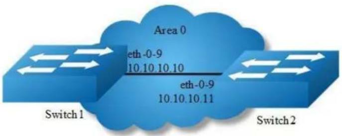
Figure 5-11 ospf
This example shows the minimum configuration required for enabling OSPF on an interface Switch1 and 2 are two routers in Area 0 connecting to network 10.10.10.0/24

NOTE
Configure one interface so that it belongs to only one area. However, you can configure different interfaces on a router to belong to different areas.
step 1 Enter the configure mode
Switch# configure terminal
step 2 Enter the interface configure mode, set the attributes and ip address
Configure on Switch1:
Switch(config)# interface eth-0-9
Switch(config-if)# no switchport
Switch(config-if)# no shutdown
Switch(config-if)# ip address 10.10.10.10/24
Switch(config-if)# exit
Configure on Switch2:
Switch(config)# interface eth-0-9
Switch(config-if)# no switchport
Switch(config-if)# no shutdown
Switch(config-if)# ip address 10.10.10.11/24
Switch(config-if)# exit
step 3 Configure the Routing process and associate the network with a specified OSPF area
Configure on Switch1:
Switch(config)# router ospf 100
Switch(config-router)# network 10.10.10.0/24 area 0
Configure on Switch2:
Switch(config)# router ospf 200
Switch(config-router)# network 10.10.10.0/24 area 0
Note: To using OSPF among two devices which are directly connected, the area IDs must be same. The ospf process IDs can be same or different.
step 4 Exit the configure mode
Switch(config-router)# end
step 5 Validation
Use the following command to display the database of ospf:
Switch# show ip ospf database
OSPF Router with ID (10.10.10.10) (Process ID 100)
Router Link States (Area 0)
Link ID ADV Router Age Seq# CkSum Link count
10.10.10.10 10.10.10.10 26 0x80000006 0x1499 1
10.10.10.11 10.10.10.11 27 0x80000003 0x1895 1
Net Link States (Area 0)
Link ID ADV Router Age Seq# CkSum
10.10.10.10 10.10.10.10 26 0x80000001 0xdfd8
Use the following command to display the interface of ospf:
Switch# show ip ospf interface
eth-0-9 is up, line protocol is up
Internet Address 10.10.10.10/24, Area 0, MTU 1500
Process ID 100, Router ID 10.10.10.10, Network Type BROADCAST, Cost: 1
Transmit Delay is 1 sec, State DR, Priority 1, TE Metric 1
Designated Router (ID) 10.10.10.10, Interface Address 10.10.10.10
Backup Designated Router (ID) 10.10.10.11, Interface Address 10.10.10.11
Timer intervals configured, Hello 10, Dead 40, Wait 40, Retransmit 5
Hello due in 00:00:06
Neighbor Count is 1, Adjacent neighbor count is 1
Crypt Sequence Number is 1527047183
Hello received 25 sent 576, DD received 4 sent 4
LS-Req received 1 sent 1, LS-Upd received 3 sent 3
LS-Ack received 2 sent 2, Discarded 0
Use the following command to display the neighbor of ospf:
Switch1:
Switch# show ip ospf neighbor
OSPF process 100:
Neighbor ID Pri State Dead Time Address Interface
10.10.10.11 1 Full/Backup 00:00:33 10.10.10.11 eth-0-9
Switch2:
Switch# show ip ospf neighbor
OSPF process 200:
Neighbor ID Pri State Dead Time Address Interface
10.10.10.10 1 Full/DR 00:00:33 10.10.10.10 eth-0-9
Use the following command to display the ospf routes:
Switch# show ip ospf route
OSPF process 100:
Codes: C - connected, D - Discard, O - OSPF, IA - OSPF inter area
N1 - OSPF NSSA external type 1, N2 - OSPF NSSA external type 2
E1 - OSPF external type 1, E2 - OSPF external type 2
C 10.10.10.0/24 [1] is directly connected, eth-0-9, Area 0
Configuring Priority
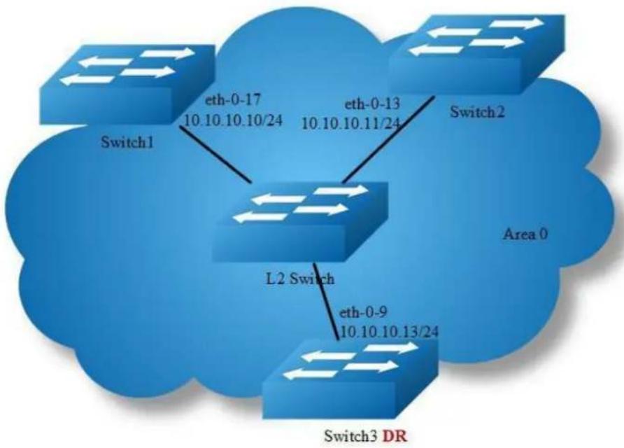
flowchart
graph TD
A["Switch1"] -->|eth-0-17 10.10.10.10/24| B["L2 Switch"]
C["Switch2"] -->|eth-0-13 10.10.10.11/24| B
D["Switch3 DR"] -->|eth-0-9 10.10.10.13/24| B
B --> E["Area 0"]
Figure 5-12 ospf priority
This example shows the configuration for setting the priority for an interface You can set a high priority for a router to make it the Designated Router (DR). Router Switch3 is configured to have a priority of 10, which is higher than the default priority (default priority is 1) of Switch1 and 2; making it the DR.
step 1 Enter the configure mode
Switch# configure terminal
step 2 Enter the interface configure mode, set the attributes and ip address
Configure on Switch1:
Switch(config)# interface eth-0-17
Switch(config-if)# no switchport
Switch(config-if)# no shutdown
Switch(config-if)# ip address 10.10.10.10/24
Switch(config-if)# quit
Configure on Switch2:
Switch(config)# interface eth-0-13
Switch(config-if)# no switchport
Switch(config-if)# no shutdown
Switch(config-if)# ip address 10.10.10.11/24
Switch(config-if)# quit
Configure on Switch3:
Switch(config)# interface eth-0-9
Switch(config-if)# no switchport
Switch(config-if)# no shutdown
Switch(config-if)# ip address 10.10.10.13/24
Switch(config-if)# quit
Configure on L2 Switch:
Switch(config)# interface eth-0-9
Switch(config-if)# no shutdown
Switch(config-if)# quit
Switch(config)# interface eth-0-13
Switch(config-if)# no shutdown
Switch(config-if)# quit
Switch(config)# interface eth-0-17
Switch(config-if)# no shutdown
Switch(config-if)# quit
step 3 Specify the router priority
Configure on Switch3:
Switch(config)# interface eth-0-9
Switch(config-if)# ip ospf priority 10
Switch(config-if)# quit
step 4 Configure the Routing process and associate the network with a specified OSPF area
Switch(config)# router ospf 100
Switch(config-router)# network 10.10.10.0/24 area 0
Switch(config-if)# quit
step 5 Exit the configure mode
Switch(config)# end
step 6 Validation
Use the following command to display the neighbor of ospf:
Switch1:
Switch# show ip ospf neighbor
OSPF process 100:
| Neighbor ID | Pri | State | Dead Time | Address | Interface |
| 10.10.10.11 | 1 | Full/Backup | 00:00:31 | 10.10.10.11 | eth-0-17 |
| 10.10.10.13 | 10 | Full/DR | 00:00:38 | 10.10.10.13 | eth-0-17 |
Switch2:
Switch# show ip ospf neighbor
OSPF process 100:
| Neighbor ID | Pri | State | Dead Time | Address | Interface |
| 10.10.10.10 | 1 | Full/DROther | 00:00:39 | 10.10.10.10 | eth-0-13 |
| 10.10.10.13 | 10 | Full/DR | 00:00:32 | 10.10.10.13 | eth-0-13 |
Switch3:
Switch# show ip ospf neighbor
OSPF process 100:
| Neighbor ID | Pri | State | Dead Time | Address | Interface |
| 10.10.10.10 | 1 | Full/DROther | 00:00:37 | 10.10.10.10 | eth-0-9 |
| 10.10.10.11 | 1 | Full/Backup | 00:00:32 | 10.10.10.11 | eth-0-9 |
Use the following command to display the interface of ospf:
Switch1:
Switch# show ip ospf interface
eth-0-17 is up, line protocol is up
Internet Address 10.10.10.10/24, Area 0, MTU 1500
Process ID 100, Router ID 10.10.10.10, Network Type BROADCAST, Cost: 1
Transmit Delay is 1 sec, State DROther, Priority 1, TE Metric 1
Designated Router (ID) 10.10.10.13, Interface Address 10.10.10.13
Backup Designated Router (ID) 10.10.10.11, Interface Address 10.10.10.11
Timer intervals configured, Hello 10, Dead 40, Wait 40, Retransmit 5
Hello due in 00:00:10
Neighbor Count is 2, Adjacent neighbor count is 2
Crypt Sequence Number is 1527056133
Hello received 106 sent 54, DD received 8 sent 9
LS-Req received 2 sent 3, LS-Upd received 8 sent 5
LS-Ack received 9 sent 5, Discarded 3
Switch2:
Switch# show ip ospf interface
eth-0-13 is up, line protocol is up
Internet Address 10.10.10.11/24, Area 0, MTU 1500
Process ID 100, Router ID 10.10.10.11, Network Type BROADCAST, Cost: 1
Transmit Delay is 1 sec, State Backup, Priority 1, TE Metric 1
Designated Router (ID) 10.10.10.13, Interface Address 10.10.10.13
Backup Designated Router (ID) 10.10.10.11, Interface Address 10.10.10.11
Timer intervals configured, Hello 10, Dead 40, Wait 40, Retransmit 5
Hello due in 00:00:10
Neighbor Count is 2, Adjacent neighbor count is 2
Crypt Sequence Number is 1527056130
Hello received 110 sent 56, DD received 8 sent 7
LS-Req received 3 sent 2, LS-Upd received 12 sent 6
LS-Ack received 11 sent 8, Discarded 0
Switch3:
Switch# show ip ospf interface
eth-0-9 is up, line protocol is up
Internet Address 10.10.10.13/24, Area 0, MTU 1500
Process ID 100, Router ID 10.10.10.13, Network Type BROADCAST, Cost: 1
Transmit Delay is 1 sec, State DR, Priority 10, TE Metric 1
Designated Router (ID) 10.10.10.13, Interface Address 10.10.10.13
Backup Designated Router (ID) 10.10.10.11, Interface Address 10.10.10.11
Timer intervals configured, Hello 10, Dead 40, Wait 40, Retransmit 5
Hello due in 00:00:01
Neighbor Count is 2, Adjacent neighbor count is 2
Crypt Sequence Number is 1527056127
Hello received 32 sent 16, DD received 9 sent 9
LS-Req received 2 sent 2, LS-Upd received 11 sent 8
LS-Ack received 10 sent 8, Discarded 0
1.3.6 Configuring OSPF Area Parameters
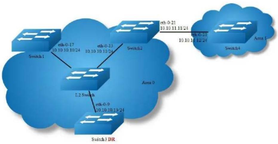
flowchart
graph TD
Switch1["Switch 1"] -->|eth-0-17 10.10 10.10/24| L2Switch["L2 Switch"]
L2Switch -->|eth-0-9 10.10 10.13/24| Switch2["Switch 2"]
Switch2 -->|eth-0-21 10.10 10.11 11/24| Switch4["Switch 4"]
Switch4 -->|eth-0-21 10.10 10.12 24| Area1["Area 1"]
Switch3["Switch 3 DR"] -->|eth-0-9 10.10 10.13/24| L2Switch
L2Switch -->|Area 0| Switch2
Switch3 -->|Area 0| Switch4
Figure 5-13 ospf area
You can optionally configure several OSPF area parameters. These parameters include authentication for password-based protection against unauthorized access to an area and stub areas. Stub areas are areas into which information on external routes is not sent. Instead, the area border router (ABR) generates a default external route into the stub area for destinations outside the autonomous system (AS).
Route summarization is the consolidation of advertised addresses into a single summary route to be advertised by other areas. If network numbers are contiguous,
you can use the area range router configuration command to configure the ABR to advertise a summary route that covers all networks in the range.
step 1 Enter the configure mode
Switch# configure terminal
step 2 Enter the interface configure mode, set the attributes and ip address
Configure on Switch1:
Switch(config)# interface eth-0-17
Switch(config-if)# no switchport
Switch(config-if)# no shutdown
Switch(config-if)# ip address 10.10.10.10/24
Switch(config-if)# quit
Configure on Switch2:
Switch(config)# interface eth-0-13
Switch(config-if)# no switchport
Switch(config-if)# no shutdown
Switch(config-if)# ip address 10.10.10.11/24
Switch(config-if)# quit
Switch(config)# interface eth-0-21
Switch(config-if)# no switchport
Switch(config-if)# no shutdown
Switch(config-if)# ip address 10.10.11.11/24
Switch(config-if)# quit
Configure on Switch3:
Switch(config)# interface eth-0-9
Switch(config-if)# no switchport
Switch(config-if)# no shutdown
Switch(config-if)# ip address 10.10.10.13/24
Switch(config-if)# quit
Configure on Switch4:
Switch(config)# interface eth-0-21
Switch(config-if)# no switchport
Switch(config-if)# no shutdown
Switch(config-if)# ip address 10.10.11.12/24
Switch(config-if)# quit
Configure on L2 Switch:
Switch(config)# interface eth-0-9
Switch(config-if)# no shutdown
Switch(config-if)# quit
Switch(config)# interface eth-0-13
Switch(config-if)# no shutdown
Switch(config-if)# quit
Switch(config)# interface eth-0-17
Switch(config-if)# no shutdown
Switch(config-if)# quit
step 3 Set the ospf priority on the interface
Configure on Switch3:
Switch(config)# interface eth-0-9
Switch(config-if)# ip ospf priority 10
Switch(config-if)# quit
step 4 Configure the Routing process and associate the network with a specified OSPF area
Configure on Switch1:
Switch(config)# router ospf 100
Switch(config-router)# network 10.10.10.0/24 area 0
Switch(config-router)# quit
Configure on Switch2:
Switch(config)# router ospf 100
Switch(config-router)# network 10.10.10.0/24 area 0
Switch(config-router)# network 10.10.11.0/24 area 1
Switch(config-router)# area 0 range 10.10.10.0/24
Switch(config-router)# area 1 stub no-summary
Switch(config-router)# quit
Configure on Switch3:
Switch(config)# router ospf 100
Switch(config-router)# network 10.10.10.0/24 area 0
Switch(config-router)# quit
Configure on Switch4:
Switch(config)# router ospf 200
Switch(config-router)# network 10.10.11.0/24 area 1
Switch(config-router)# area 1 stub no-summary
Switch(config-router)# quit
step 5 Exit the configure mode
Switch(config)# end
step 6 Validation
Use the following command to display the ospf routes:
Switch1:
Switch# show ip route
Codes: K - kernel, C - connected, S - static, R - RIP, B - BGP
O - OSPF, IA - OSPF inter area
N1 - OSPF NSSA external type 1, N2 - OSPF NSSA external type 2
E1 - OSPF external type 1, E2 - OSPF external type 2
i - IS-IS, L1 - IS-IS level-1, L2 - IS-IS level-2, ia - IS-IS inter area
Dc - DHCP Client
[*] - [AD/Metric]
* - candidate default
C 10.10.10.0/24 is directly connected, eth-0-17
C 10.10.10.10/32 is in local loopback, eth-0-17
O IA 10.10.11.0/24 [110/2] via 10.10.10.11, eth-0-17, 00:00:04
Switch2:
Switch# show ip route
Codes: K - kernel, C - connected, S - static, R - RIP, B - BGP
O - OSPF, IA - OSPF inter area
N1 - OSPF NSSA external type 1, N2 - OSPF NSSA external type 2
E1 - OSPF external type 1, E2 - OSPF external type 2
i - IS-IS, L1 - IS-IS level-1, L2 - IS-IS level-2, ia - IS-IS inter area
Dc - DHCP Client
[*] - [AD/Metric]
* - candidate default
C 10.10.10.0/24 is directly connected, eth-0-13
C 10.10.10.11/32 is in local loopback, eth-0-13
C 10.10.11.0/24 is directly connected, eth-0-21
C 10.10.11.11/32 is in local loopback, eth-0-21
Switch3:
Switch# show ip route
Codes: K - kernel, C - connected, S - static, R - RIP, B - BGP
O - OSPF, IA - OSPF inter area
N1 - OSPF NSSA external type 1, N2 - OSPF NSSA external type 2
E1 - OSPF external type 1, E2 - OSPF external type 2
i - IS-IS, L1 - IS-IS level-1, L2 - IS-IS level-2, ia - IS-IS inter area
Dc - DHCP Client
[*] - [AD/Metric]
* - candidate default
C 10.10.10.0/24 is directly connected, eth-0-9
C 10.10.10.13/32 is in local loopback, eth-0-9
O IA 10.10.11.0/24 [110/2] via 10.10.10.11, eth-0-9, 00:06:29
Switch4:
Switch# show ip route
Codes: K - kernel, C - connected, S - static, R - RIP, B - BGP
O - OSPF, IA - OSPF inter area
N1 - OSPF NSSA external type 1, N2 - OSPF NSSA external type 2
E1 - OSPF external type 1, E2 - OSPF external type 2
i - IS-IS, L1 - IS-IS level-1, L2 - IS-IS level-2, ia - IS-IS inter area
Dc - DHCP Client
[*] - [AD/Metric]
* - candidate default
Gateway of last resort is 10.10.11.11 to network 0.0.0.0
O*IA 0.0.0.0/0 [110/2] via 10.10.11.11, eth-0-21, 00:12:46
C 10.10.10.0/24 is directly connected, eth-0-21
C 10.10.10.12/32 is in local loopback, eth-0-21
Redistributing Routes into OSPF
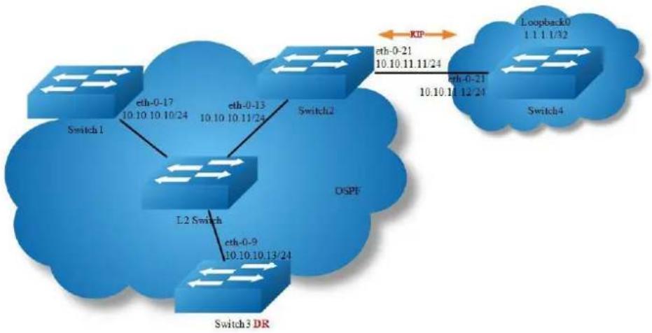
flowchart
graph TD
Switch1["Switch 1"] -->|eth-0-17 10.10.10.10/24| Switch2["Switch 2"]
Switch2 -->|eth-0-13 10.10.10.11/24| Switch3["Switch 3 DR"]
Switch3 -->|eth-0-9 10.10.10.13/24| Switch4["Switch 4"]
Switch4 -->|eth-0-21 10.10.10.11/24| Loopback0["Loopback 0 1.1.1.1/32"]
Switch2 <-->|KIP| Loopback0
Switch3 <-->|DSPF| Switch4
Figure 5-14 ospf redistribute
In this example the configuration causes RIP routes to be imported into the OSPF routing table and advertised as Type 5 External LSAs into Area 0.
step 1 Enter the configure mode
Switch# configure terminal
step 2 Enter the interface configure mode, set the attributes and ip address
Configure on Switch1:
Switch(config)# interface eth-0-17
Switch(config-if)# no switchport
Switch(config-if)# no shutdown
Switch(config-if)# ip address 10.10.10.10/24
Switch(config-if)# quit
Configure on Switch2:
Switch(config)# interface eth-0-13
Switch(config-if)# no switchport
Switch(config-if)# no shutdown
Switch(config-if)# ip address 10.10.10.11/24
Switch(config-if)# quit
Switch(config)# interface eth-0-21
Switch(config-if)# no switchport
Switch(config-if)# no shutdown
Switch(config-if)# ip address 10.10.11.11/24
Switch(config-if)# quit
Configure on Switch3:
Switch(config)# interface eth-0-9
Switch(config-if)# no switchport
Switch(config-if)# no shutdown
Switch(config-if)# ip address 10.10.10.13/24
Switch(config-if)# quit
Configure on Switch4:
Switch(config)# interface eth-0-21
Switch(config-if)# no switchport
Switch(config-if)# no shutdown
Switch(config-if)# ip address 10.10.11.12/24
Switch(config-if)# quit
Switch(config)# interface loopback 0
Switch(config-if)# ip address 1.1.1.1/32
Switch(config-if)# quit
Configure on L2 Switch:
Switch(config)# interface eth-0-9
Switch(config-if)# no shutdown
Switch(config-if)# quit
Switch(config)# interface eth-0-13
Switch(config-if)# no shutdown
Switch(config-if)# quit
Switch(config)# interface eth-0-17
Switch(config-if)# no shutdown
Switch(config-if)# quit
step 3 Set the ospf priority on the interface
Configure on Switch3:
Switch(config)# interface eth-0-9
Switch(config-if)# ip ospf priority 10
Switch(config-if)# quit
step 4 Configure the Routing process and associate the network with a specified OSPF area
Configure on Switch1:
Switch(config)# router ospf 100
Switch(config-router)# network 10.10.10.0/24 area 0
Switch(config-router)# quit
Configure on Switch2:
Switch(config)# router ospf 100
Switch(config-router)# network 10.10.10.0/24 area 0
Switch(config-router)# redistribute connected
Switch(config-router)# redistribute rip
Switch(config-router)# quit
Configure on Switch3:
Switch(config)# router ospf 100
Switch(config-router)# network 10.10.10.0/24 area 0
Switch(config-router)# quit
step 5 Enable RIP routing process and associate networks
Configure on Switch2:
Switch(config)# router rip
Switch(config-router)# network 10.10.11.0/24
Switch(config-router)# redistribute connected
Switch(config-router)# quit
Configure on Switch4:
Switch(config)# router rip
Switch(config-router)# network 10.10.11.0/24
Switch(config-router)# network 1.1.1.1/32
Switch(config-router)# redistribute connected
Switch(config-router)# quit
step 6 Exit the configure mode
Switch(config)# end
step 6 Validation
Use the following command to display the ospf routes:
Switch1:
Switch# show ip route
Codes: K - kernel, C - connected, S - static, R - RIP, B - BGP
O - OSPF, IA - OSPF inter area
N1 - OSPF NSSA external type 1, N2 - OSPF NSSA external type 2
E1 - OSPF external type 1, E2 - OSPF external type 2
i - IS-IS, L1 - IS-IS level-1, L2 - IS-IS level-2, ia - IS-IS inter area
Dc - DHCP Client
[*] - [AD/Metric]
* - candidate default
O E2 1.1.1.1/32 [110/20] via 10.10.10.11, eth-0-17, 00:01:54
C 10.10.10.0/24 is directly connected, eth-0-17
C 10.10.10.10/32 is in local loopback, eth-0-17
O E2 10.10.11.0/24 [110/20] via 10.10.10.11, eth-0-17, 00:03:49
Switch2:
Switch# show ip route
Codes: K - kernel, C - connected, S - static, R - RIP, B - BGP
O - OSPF, IA - OSPF inter area
N1 - OSPF NSSA external type 1, N2 - OSPF NSSA external type 2
E1 - OSPF external type 1, E2 - OSPF external type 2
i - IS-IS, L1 - IS-IS level-1, L2 - IS-IS level-2, ia - IS-IS inter area
Dc - DHCP Client
[*] - [AD/Metric]
* - candidate default
R 1.1.1.1/32 [120/2] via 10.10.11.12, eth-0-21, 00:02:27
C 10.10.10.0/24 is directly connected, eth-0-13
C 10.10.10.11/32 is in local loopback, eth-0-13
C 10.10.11.0/24 is directly connected, eth-0-21
C 10.10.11.11/32 is in local loopback, eth-0-21
Switch3:
Switch# show ip route
Codes: K - kernel, C - connected, S - static, R - RIP, B - BGP
O - OSPF, IA - OSPF inter area
N1 - OSPF NSSA external type 1, N2 - OSPF NSSA external type 2
E1 - OSPF external type 1, E2 - OSPF external type 2
i - IS-IS, L1 - IS-IS level-1, L2 - IS-IS level-2, ia - IS-IS inter area
Dc - DHCP Client
[*] - [AD/Metric]
* - candidate default
O E2 1.1.1.1/32 [110/20] via 10.10.10.11, eth-0-9, 00:03:01
C 10.10.10.0/24 is directly connected, eth-0-9
C 10.10.10.13/32 is in local loopback, eth-0-9
O E2 10.10.11.0/24 [110/20] via 10.10.10.11, eth-0-9, 00:04:57
Switch4:
Switch# show ip route
Codes: K - kernel, C - connected, S - static, R - RIP, B - BGP
O - OSPF, IA - OSPF inter area
N1 - OSPF NSSA external type 1, N2 - OSPF NSSA external type 2
E1 - OSPF external type 1, E2 - OSPF external type 2
i - IS-IS, L1 - IS-IS level-1, L2 - IS-IS level-2, ia - IS-IS inter area
Dc - DHCP Client
[*] - [AD/Metric]
* - candidate default
C 1.1.1.1/32 is directly connected, loopback0
R 10.10.10.0/24 [120/2] via 10.10.11.11, eth-0-21, 00:17:36
C 10.10.11.0/24 is directly connected, eth-0-21
C 10.10.11.12/32 is in local loopback, eth-0-21
Use the following command to display the database of ospf:
Switch1:
Switch# show ip ospf database external
OSPF Router with ID (10.10.10.10) (Process ID 100)
AS External Link States
LS age: 317
Options: 0x2 (*|-|-|-|-|-|-|E|-)
LS Type: AS-external-LSA
Link State ID: 1.1.1.1 (External Network Number)
Advertising Router: 10.10.10.11
LS Seq Number: 80000001
Checksum: 0x4a47
Length: 36
Network Mask: /32
Metric Type: 2 (Larger than any link state path)
TOS: 0
Metric: 20
Forward Address: 0.0.0.0
External Route Tag: 0
LS age: 438
Options: 0x2 (*|-|-|-|-|-|-|E|-)
LS Type: AS-external-LSA
Link State ID: 10.10.11.0 (External Network Number)
Advertising Router: 10.10.10.11
LS Seq Number: 80000001
Checksum: 0x0472
Length: 36
Network Mask: /24
Metric Type: 2 (Larger than any link state path)
TOS: 0
Metric: 20
Forward Address: 0.0.0.0
External Route Tag: 0
Switch2:
Switch# show ip ospf database external
140 000 000 000 000 000 000 000 000 000 000 000 000 000 000 000 000 000 000 000 000 000 000 000 000 000 025
Switch3:
Switch# show ip ospf database external
OSPF Router with ID (10.10.10.13) (Process ID 100)
AS External Link States
LS age: 396
Options: 0x2 (*|-|-|-|-|-|-|E|-)
LS Type: AS-external-LSA
Link State ID: 1.1.1.1 (External Network Number)
Advertising Router: 10.10.10.11
LS Seq Number: 80000001
Checksum: 0x4a47
Length: 36
Network Mask: /32
Metric Type: 2 (Larger than any link state path)
TOS: 0
Metric: 20
Forward Address: 0.0.0.0
External Route Tag: 0
LS age: 517
Options: 0x2 (*||-|-|-|-|-|E|-)
LS Type: AS-external-LSA
Link State ID: 10.10.11.0 (External Network Number)
Advertising Router: 10.10.10.11
LS Seq Number: 80000001
Checksum: 0x0472
Length: 36
Network Mask: /24
Metric Type: 2 (Larger than any link state path)
TOS: 0
Metric: 20
Forward Address: 0.0.0.0
External Route Tag: 0
OSPF Cost
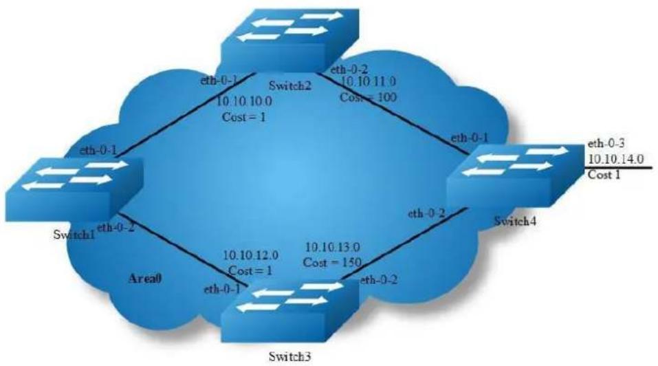
flowchart
graph TD
A["Switch1"] -->|eth-0-1| B["Switch2"]
B -->|eth-0-2| C["Switch3"]
C -->|eth-0-3| D["Switch4"]
D -->|eth-0-1| A
A -->|eth-0-1| E["Area0"]
B -->|10.10 10.0 Cost = 1| F["Cost = 1"]
C -->|10.10 12.0 Cost = 1| G["Cost = 150"]
D -->|10.10 13.0 Cost = 150| H["Cost = 100"]
E --> I["Cost = 1"]
F --> J["Cost = 1"]
G --> K["Cost = 1"]
H --> L["Cost = 1"]
I --> M["Cost = 1"]
J --> N["Cost = 1"]
K --> O["Cost = 1"]
Figure 5-15 ospf cost
You can make a route the preferred route by changing its cost. In this example, cost has been configured to make Switch2 the next hop for Switch1.
The default cost on each interface is 1(1000M speed). Interface eth2 on Switch2 has a cost of 100 and interface eth2 on Switch3 has a cost of 150. The total cost to reach(Switch4 network 10.10.14.0) through Switch2 and Switch3:
Switch2: 1+1+100 = 102
Switch3: 1+1+150 = 152
Therefore, Switch1 chooses Switch2 as its next hop for destination Switch4
step 1 Enter the configure mode
Switch# configure terminal
step 2 Enter the interface configure mode, set the attributes and ip address.
Set the ospf cost under the interface configure mode
Configure on Switch1:
Switch(config)# interface eth-0-1
Switch(config-if)# no switchport
Switch(config-if)# ip address 10.10.10.1/24
Switch(config-if)# exit
Switch(config)# interface eth-0-2
Switch(config-if)# no switchport
Switch(config-if)# ip address 10.10.12.1/24
Switch(config-if)# exit
Configure on Switch2:
Switch(config)# interface eth-0-1
Switch(config-if)# no switchport
Switch(config-if)# ip address 10.10.10.2/24
Switch(config-if)# exit
Switch(config)# interface eth-0-2
Switch(config-if)# no switchport
Switch(config-if)# ip address 10.10.11.2/24
Switch(config-if)# ip ospf cost 100
Switch(config-if)# exit
Configure on Switch3:
Switch(config)# interface eth-0-1
Switch(config-if)# no switchport
Switch(config-if)# ip address 10.10.12.2/24
Switch(config-if)# exit
Switch(config)# interface eth-0-2
Switch(config-if)# no switchport
Switch(config-if)# ip address 10.10.13.2/24
Switch(config-if)# ip ospf cost 150
Switch(config-if)# exit
Configure on Switch4:
Switch(config)# interface eth-0-1
Switch(config-if)# no switchport
Switch(config-if)# ip address 10.10.11.1/24
Switch(config-if)# exit
Switch(config)# interface eth-0-2
Switch(config-if)# no switchport
Switch(config-if)# ip address 10.10.13.1/24
Switch(config-if)# exit
Switch(config)# interface eth-0-3
Switch(config-if)# no switchport
Switch(config-if)# ip address 10.10.14.1/24
Switch(config-if)# exit
step 3 Configure the Routing process and associate the network with a specified OSPF area
Configure on Switch1:
Switch(config)# router ospf 100
Switch(config-router)# network 10.10.10.0/24 area 0
Switch(config-router)# network 10.10.12.0/24 area 0
Switch(config-router)# exit
Configure on Switch2:
Switch(config)# router ospf 100
Switch(config-router)# network 10.10.10.0/24 area 0
Switch(config-router)# network 10.10.11.0/24 area 0
Switch(config-router)# exit
Configure on Switch3:
Switch(config)# router ospf 100
Switch(config-router)# network 10.10.12.0/24 area 0
Switch(config-router)# network 10.10.13.0/24 area 0
Switch(config-router)# exit
Configure on Switch4:
Switch(config)# router ospf 100
Switch(config-router)# network 10.10.11.0/24 area 0
Switch(config-router)# network 10.10.13.0/24 area 0
Switch(config-router)# network 10.10.14.0/24 area 0
Switch(config-router)# exit
step 4 Exit the configure mode
Switch(config)# end
step 5 Validation
Use the following command to display the ospf routes:
Switch1:
Switch# show ip ospf route
OSPF process 0:
Codes: C - connected, D - Discard, O - OSPF, IA - OSPF inter area
N1 - OSPF NSSA external type 1, N2 - OSPF NSSA external type 2
E1 - OSPF external type 1, E2 - OSPF external type 2
C 10.10.10.0/24 [1] is directly connected, eth-0-1, Area 0
O 10.10.11.0/24 [101] via 10.10.10.2, eth-0-1, Area 0
C 10.10.12.0/24 [1] is directly connected, eth-0-2, Area 0
O 10.10.13.0/24 [102] via 10.10.10.2, eth-0-1, Area 0
O 10.10.14.0/24 [102] via 10.10.10.2, eth-0-1, Area 0
Switch2:
Switch# show ip ospf route
OSPF process 100:
Codes: C - connected, D - Discard, O - OSPF, IA - OSPF inter area
N1 - OSPF NSSA external type 1, N2 - OSPF NSSA external type 2
E1 - OSPF external type 1, E2 - OSPF external type 2
C 10.10.10.0/24 [10] is directly connected, eth-0-1, Area 0
C 10.10.11.0/24 [100] is directly connected, eth-0-2, Area 0
O 10.10.12.0/24 [11] via 10.10.10.1, eth-0-1, Area 0
O 10.10.13.0/24 [101] via 10.10.11.1, eth-0-2, Area 0
O 10.10.14.0/24 [101] via 10.10.11.1, eth-0-2, Area 0
Switch3:
Switch# show ip ospf route
OSPF process 100:
Codes: C - connected, D - Discard, O - OSPF, IA - OSPF inter area
N1 - OSPF NSSA external type 1, N2 - OSPF NSSA external type 2
E1 - OSPF external type 1, E2 - OSPF external type 2
O 10.10.10.0/24 [1] via 10.10.12.1, eth-0-1, Area 0
O 10.10.11.0/24 [101] via 10.10.12.1, eth-0-1, Area 0
C 10.10.12.0/24 [1] is directly connected, eth-0-1, Area 0
O 10.10.13.0/24 [102] via 10.10.12.1, eth-0-1, Area 0
O 10.10.14.0/24 [102] via 10.10.12.1, eth-0-1, Area 0
Switch4:
Switch# show ip route
Codes: K - kernel, C - connected, S - static, R - RIP, B - BGP
O - OSPF, IA - OSPF inter area
N1 - OSPF NSSA external type 1, N2 - OSPF NSSA external type 2
E1 - OSPF external type 1, E2 - OSPF external type 2
i - IS-IS, L1 - IS-IS level-1, L2 - IS-IS level-2, ia - IS-IS inter area
[*] - [AD/Metric]
* - candidate default
O 10.10.10.0/24 [110/1] via 10.10.11.2, eth-0-1, 00:06:27
C 10.10.11.0/24 is directly connected, eth-0-1
O 10.10.12.0/24 [110/1] via 10.10.13.2, eth-0-2, 00:06:17
C 10.10.13.0/24 is directly connected, eth-0-2
C 10.10.14.0/24 is directly connected, eth-0-3
Configuring OSPF authentications
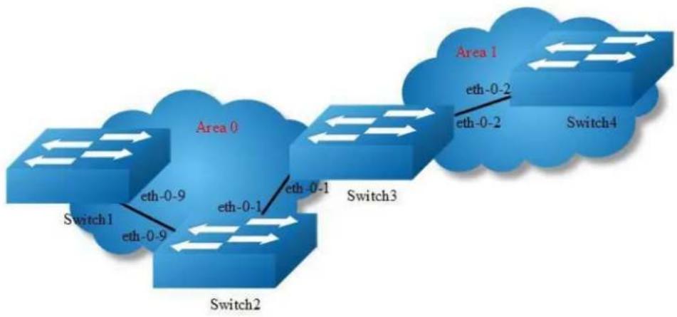
flowchart
graph LR
A["Switch1"] -->|eth-0-9| B["Area 0"]
B -->|eth-0-1| C["Switch2"]
C -->|eth-0-1| D["Switch3"]
D -->|eth-0-2| E["Area 1"]
E -->|eth-0-2| F["Switch4"]
style A fill:#cce5ff,stroke:#333
style B fill:#cce5ff,stroke:#333
style C fill:#cce5ff,stroke:#333
style D fill:#cce5ff,stroke:#333
style E fill:#cce5ff,stroke:#333
style F fill:#cce5ff,stroke:#333
Figure 5-16 ospf authentication
In our implementation there are three types of OSPF authentications-Null authentication (Type 0), Simple Text (Type 1) authentication and MD5 (Type 2) authentication. With null authentication, routing exchanges over the network are not authenticated. In Simple Text authentication, the authentication type is the same for all routers that communicate using OSPF in a network. For MD5 authentication, you configure a key and a key-id on each router. The router generates a message digest on the basis of the key, key ID and the OSPF packet and adds it to the OSPF packet.
The Authentication type can be configured on a per-interface basis or a per-area basis. Additionally, Interface and Area authentication can be used together. Area authentication is used for an area and interface authentication is used for a specific interface in the area. If the Interface authentication type is different from Area authentication type, Interface authentication type overrides the Area authentication type. If the Authentication type is not specified for an interface, the Authentication type for the area is used. The authentication command descriptions contain details of each type of authentication. Refer to the OSPF Command Reference for OSPF authentication commands.
In the example below, Switch1 and B are configured for both the interface and area authentications. The authentication type of interface eth-0-9 on Switch1 and interface eth-0-9 on Switch2 is null authentication mode. The authentication type of interface eth-0-1 on Switch2 and interface eth-0-1 on Switch3 is simple authentication mode. The authentication type of interface eth-0-2 on Switch3 and
interface eth-0-2 on Switch4 is MD5 authentication mode in area1, if you define area 1 authentication type first, you needn't define interface authentication type, only define authentication key value.
step 1 Enter the configure mode
Switch# configure terminal
step 2 Enter the interface configure mode, set the attributes and ip address. Set the ospf authentication under the interface configure mode
Configure on Switch1:
Switch(config)#interface eth-0-9
Switch(config-if)#no switchport
Switch(config-if)#ip address 9.9.9.1/24
Switch(config-if)#ip ospf authentication
Switch(config-if)#ip ospf authentication null
Switch(config-if)# exit
Configure on Switch2:
Switch(config)#interface eth-0-1
Switch(config-if)#no switchport
Switch(config-if)#ip address 1.1.1.1/24
Switch(config-if)#ip ospf authentication
Switch(config-if)#ip ospf authentication-key test
Switch(config-if)# exit
Switch(config)#interface eth-0-9
Switch(config-if)#no switchport
Switch(config-if)#ip address 9.9.9.2/24
Switch(config-if)#ip ospf authentication
Switch(config-if)#ip ospf authentication null
Switch(config-if)# exit
Configure on Switch3:
Switch(config)#interface eth-0-2
Switch(config-if)#no switchport
Switch(config-if)#ip address 2.2.2.1/24
Switch(config-if)#ip ospf message-digest-key 2 md5 ospf
Switch(config-if)#exit
Switch(config)#interface eth-0-1
Switch(config-if)#no switchport
Switch(config-if)#ip address 1.1.1.2/24
Switch(config-if)#ip ospf authentication
Switch(config-if)#ip ospf authentication-key test
Switch(config-if)#exit
Configure on Switch4:
Switch(config)#interface eth-0-2
Switch(config-if)#no switchport
Switch(config-if)#ip address 2.2.2.2/24
Switch(config-if)#ip ospf message-digest-key 2 md5 ospf
Switch(config-if)#exit
step 3 Configure the Routing process and associate the network with a specified OSPF area
Configure on Switch1:
Switch(config)# router ospf
Switch(config-router)# network 9.9.9.0/24 area 0
Switch(config-router)# exit
Configure on Switch2:
Switch(config)# router ospf
Switch(config-router)# network 9.9.9.0/24 area 0
Switch(config-router)# network 1.1.1.0/24 area 0
Switch(config-router)# exit
Configure on Switch3:
Switch(config)# router ospf
Switch(config-router)# area 1 authentication message-digest
Switch(config-router)# network 2.2.2.0/24 area 1
Switch(config-router)# network 1.1.1.0/24 area 0
Switch(config-router)# exit
Configure on Switch4:
Switch(config)# router ospf
Switch(config-router)# area 1 authentication message-digest
Switch(config-router)# network 2.2.2.0/24 area 1
Switch(config-router)# exit
step 4 Exit the configure mode
Switch(config)# end
step 5 Validation
Use the following command to display the neighbor of ospf:
Switch1:
Switch# show ip ospf neighbor
OSPF process 0:
Neighbor ID Pri State Dead Time Address Interface
9.9.9.2 1 Full/DR 00:00:38 9.9.9.2 eth-0-9
Switch2:
Switch# show ip ospf neighbor
OSPF process 0:
Neighbor ID Pri State Dead Time Address Interface
2.2.2.1 1 Full/Backup 00:00:35 1.1.1.2 eth-0-1
1.1.1.1 1 Full/Backup 00:00:38 9.9.9.1 eth-0-9
Switch3:
Switch# show ip ospf neighbor
OSPF process 0:
Neighbor ID Pri State Dead Time Address Interface
9.9.9.2 1 Full/DR 00:00:35 1.1.1.1 eth-0-1
2.2.2.2 1 Full/DR 00:00:38 2.2.2.2 eth-0-2
Switch4:
Switch# show ip ospf neighbor
OSPF process 0:
Neighbor ID Pri State Dead Time Address Interface
2.2.2.1 1 Full/Backup 00:00:35 2.2.2.1 eth-0-2
Use the following command to display the interface of ospf:
Switch3:
Switch# show ip ospf interface
eth-0-1 is up, line protocol is up
Internet Address 1.1.1.2/24, Area 0, MTU 1500
Process ID 0, Router ID 2.2.2.1, Network Type BROADCAST, Cost: 1
Transmit Delay is 1 sec, State Backup, Priority 1, TE Metric 1
Designated Router (ID) 9.9.9.2, Interface Address 1.1.1.1
Backup Designated Router (ID) 2.2.2.1, Interface Address 1.1.1.2
Timer intervals configured, Hello 10, Dead 40, Wait 40, Retransmit 5
Hello due in 00:00:01
Neighbor Count is 1, Adjacent neighbor count is 1
Crypt Sequence Number is 1301244696
Hello received 385 sent 384, DD received 3 sent 5
LS-Req received 1 sent 1, LS-Upd received 11 sent 14
LS-Ack received 12 sent 10, Discarded 1
Simple password authentication enabled
Use the following command to display the protocol state of ospf process:
Switch3:
Switch# show ip ospf
Routing Process "ospf 0" with ID 2.2.2.1
Process uptime is 1 hour 7 minutes
Process bound to VRF default
Conforms to RFC2328, and RFC1583 Compatibility flag is disabled
Supports only single TOS(TOSO) routes
Supports opaque LSA
This router is an ABR, ABR Type is Alternative Cisco (RFC3509)
SPF schedule delay 5 secs, Hold time between two SPFs 10 secs
Refresh timer 10 secs
Number of incoming current DD exchange neighbors 0/5
Number of outgoing current DD exchange neighbors 0/5
Number of external LSA 0. Checksum 0x000000
Number of opaque AS LSA 0. Checksum 0x000000
Number of non-default external LSA 0
External LSA database is unlimited.
Number of LSA originated 17
Number of LSA received 57
Number of areas attached to this router: 2
Area 0 (BACKBONE)
Number of interfaces in this area is 1(1)
Number of fully adjacent neighbors in this area is 1
Area has no authentication
SPF algorithm last executed 01:06:56.340 ago
SPF algorithm executed 16 times
Number of LSA 6. Checksum 0x034b09
Area 1
Number of interfaces in this area is 1(1)
Number of fully adjacent neighbors in this area is 1
Number of fully adjacent virtual neighbors through this area is 0
Area has message digest authentication
SPF algorithm last executed 00:03:29.430 ago
SPF algorithm executed 17 times
Number of LSA 5. Checksum 0x0230e3
5.3.3 Application cases
N/A
Configuring OSPF authentications password encryption
When we configure the OSPF authentication, the authentication-key is simple words.
Thus, the authentication-key is shown as simple words in system. In order to increase
the safety of our system, the OSPF authentication-key is shown as encryption words.
Additionally, the system now supports configuring OSPF authentication with encryption words.
Simple Password
step 1 Enter the configure mode
Switch# configure terminal
step 2 Enter the interface configure mode, set the attributes and ip address. Set the ospf authentication under the interface configure mode and simple password
Switch(config)#interface eth-0-9
Switch(config-if)#no switchport
Switch(config-if)#ip address 9.9.9.1/24
Switch(config-if)#ip ospf authentication
Switch(config-if)#ip ospf authentication-key test
Switch(config-if)# exit
step 3 Enter the configure mode, translate to encryption password and show it
Switch(config)# service password-encryption
Switch(config)# show running-config
!
service password-encryption
!
interface eth-0-9
no switchport
ip address 9.9.9.1/24
ip ospf authentication-key 8 af0443346357baf8
!
step 4 Disable the function of showing encryption password, delete the old authentication-key and set new one, then show the password
Switch(config)#no service password-encryption
Switch(config)#interface eth-0-9
Switch(config-if)#no ip ospf authentication-key
Switch(config-if)#ip ospf authentication-key test123
Switch(config-if)# exit
Switch(config)# show running-config
!
no service password-encryption
!
interface eth-0-9
no switchport
ip address 9.9.9.1/24
ip ospf authentication-key test123
!
step 5 Configuring OSPF encryption password
Switch(config)#interface eth-0-9
Switch(config-if)#no ip ospf authentication-key
Switch(config-if)#ip ospf authentication-key 8 af0443346357baf8
Switch(config-if)# exit
Switch(config)# show running-config
!
no service password-encryption
!
interface eth-0-9
no switchport
ip address 9.9.9.1/24
ip ospf authentication-key test123
MD5 Password
step 1 Enter the configure mode
Switch# configure terminal
step 2 Enter the interface configure mode, set the attributes and ip address. Set the ospf authentication under the interface configure mode and simple password
Switch(config)#interface eth-0-9
Switch(config-if)#no switchport
Switch(config-if)#ip address 9.9.9.1/24
Switch(config-if)#ip ospf authentication message-digest
Switch(config-if)#ip ospf message-digest-key 1 md5 ospf
Switch(config-if)# exit
step 3 Enter the configure mode, translate to encryption password and show it
Switch(config)# service password-encryption
Switch(config)# show running-config
!
service password-encryption
!
interface eth-0-9
no switchport
ip address 9.9.9.1/24
ip ospf authentication message-digest
ip ospf message-digest-key 1 md5 8 1f0276567f2db31f
!
step 4 Disable the function of showing encryption password, delete the old authentication-key and set new one, then show the password
Switch(config)#no service password-encryption
Switch(config)#interface eth-0-9
Switch(config-if)#no ip ospf message-digest-key 1
Switch(config-if)#ip ospf message-digest-key 1 md5 ospf123
Switch(config-if)# exit
Switch(config)# show running-config
!
no service password-encryption
!
interface eth-0-9
no switchport
ip address 9.9.9.1/24
ip ospf authentication message-digest
ip ospf message-digest-key 1 md5 ospf123
!
step 5 Configuring OSPF encryption password
Switch(config)#interface eth-0-9 Switch(config-if)#no ip ospf message-digest-key 1
Switch(config-if)#ip ospf message-digest-key 1 md5 8 1f0276567f2db31f
Switch(config-if)# exit
Switch(config)# show running-config
!
no service password-encryption
!
interface eth-0-9
no switchport
ip address 9.9.9.1/24
ip ospf authentication message-digest
ip ospf message-digest-key 1 md5 8 1f0276567f2db31f
!
5.3.4 Application cases
N/A
5.4 Configuring Prefix-list
5.4.1 Overview
Function Introduction
Routing Policy is the technology for modifying route information to change traffic route. Prefix list is a kind of route policies that used to control and modify routing information. A prefix list is identified by list name and contains one or more ordered entries which are processed sequentially. Each entry provides a matched range for network prefix and has a unique sequence number in the list. In the matching process, switch will check entries orderly. If a entry matches conditions, this process would finish.
Principle Description
N/A
5.4.2 Configuration
Basic Configuration
step 1 Enter the configure mode
Switch# configure terminal
step 2 Create a prefix-list
Note: Create a prefix-list. If the sequence of the rule is not specified, system should automatically assign an sequence number for it. Support different actions such as permit and deny. Support to add description string for a prefix-list.
Switch(config)# ip prefix-list test seq 1 deny 35.0.0.0/8 le 16
Switch(config)# ip prefix-list test permit any
Switch(config)# ip prefix-list test description this prefix list is fot test
Switch(config)# ip prefix-list test permit 36.0.0.0/24
step 3 Exit the configure mode
Switch(config)# end
step 4 Validation
Use the following command to display the prefix-list:
Switch# show ip prefix-list detail
Prefix-list list number: 1
Prefix-list entry number: 3
Prefix-list with the last deletion/insertion: test
ip prefix-list test:
Description: this prefix list is fot test
count: 3, range entries: 0, sequences: 1 - 10
seq 1 deny 35.0.0.0/8 le 16 (hit count: 0, refcount: 0)
seq 5 permit any (hit count: 0, refcount: 0)
seq 10 permit 36.0.0.0/24 (hit count: 0, refcount: 0)
Used by rip
step 1 Enter the configure mode
Switch# configure terminal
step 2 Create a prefix-list
Switch(config)# ip prefix-list aa seq 11 deny 35.0.0.0/8 le 16
Switch(config)# ip prefix-list aa permit any
step 3 Apply the prefix-list under the router rip configure mode
Switch(config)# router rip
Switch(config-router)# distribute-list prefix aa out
Switch(config-router)# exit
step 5 Exit the configure mode
Switch(config)# end
step 6 Validation
Use the following command to display the prefix-list:
Switch# show ip prefix-list
ip prefix-list aa: 2 entries
seq 11 deny 35.0.0.0/8 le 16
seq 15 permit any
Use the following command to display the configuration of the device:
Switch# show running-config
Building configuration...
ip prefix-list aa seq 11 deny 35.0.0.0/8 le 16
ip prefix-list aa seq 15 permit any
...
router rip
distribute-list prefix aa out
Used by Route-map
step 1 Enter the configure mode
Switch# configure terminal
step 2 Create a prefix-list
Switch(config)# ip prefix-list aa seq 11 deny 3.3.3.0/8 le 24
Switch(config)# ip prefix-list aa permit any
step 3 create a route map to match the prefix-list
Switch(config)# route-map abc permit
Switch(config-route-map)# match ip address prefix-list aa
Switch(config-route-map)# set local-preference 200
Switch(config-route-map)# exit
Switch(config)# route-map abc permit 20
Switch(config-route-map)# exit
step 4 Apply the route under the router bgp configure mode
Switch(config)# router bgp 1
Switch(config-router)# neighbor 1.1.1.2 remote-as 1
Switch(config-router)# neighbor 1.1.1.2 route-map abc out
Switch(config-router)# network 2.2.2.2/32
Switch(config-router)# network 3.3.3.3/32
step 5 Exit the configure mode
Switch(config-router)# end
step 6 Validation
Use the following command to display the route map:
Switch # show route-map
route-map abc, permit, sequence 10
Match clauses:
ip address prefix-list aa
Set clauses:
local-preference 200
route-map abc, permit, sequence 20
Match clauses:
Set clauses:
Use the following command to display the configuration of the device:
Switch # show running-config
Building configuration...
ip prefix-list aa seq 11 deny 3.3.3.0/8 le 24
ip prefix-list aa seq 15 permit any
!
!
route-map abc permit 10
match ip address prefix-list aa
set local-preference 200
!
route-map abc permit 20
...
router bgp 1
neighbor 1.1.1.2 remote-as 1
!
address-family ipv4
no synchronization
network 2.2.2.2 mask 255.255.255.255
network 3.3.3.3 mask 255.255.255.255
neighbor 1.1.1.2 activate
neighbor 1.1.1.2 route-map abc out
exit-address-family
!
address-family vpnv4 unicast
no synchronization
exit-address-family
5.4.3 Application cases
N/A
5.5 Configuring Route-map
5.5.1 Overview
Function Introduction
Route-map is used to control and modify routing information. The route-map command allows redistribution of routes. It has a list of match and set commands associated with it. The match commands specify the conditions under which redistribution is allowed, and the set commands specify the particular redistribution actions to be performed if the criteria enforced by match commands are met. Route maps are used for detailed control over route distribution between routing processes. Route maps also allow policy routing, and might route packets to a different route than the obvious shortest path.
If the permit parameter is specified, and the match criteria are met, the route is redistributed as specified by set actions. If the match criteria are not met, the next route map with the same tag is tested. If the deny parameter is specified, and the match criteria are met, the route is not redistributed, and any other route maps with the same map tag are not examined. Routes are checked from line to line looking for a match. If there is no match and the bottom of the route map is reached, then the router denies the route from being redistributed. There is always an implicit deny at the end of a route map.
Specify the sequence parameter to indicate the position a new route map is to have in the list of route maps already configured with the same name.
Principle Description
N/A
5.5.2 Configuration
Configuring Route-map for OSPF
step 1 Enter the configure mode
Switch# configure terminal
step 2 Create route map and set the rule and action

NOTE
The name of route-map is up to 20 characters, in this example the name is “abc”. Two actions “permit” and “deny” are supported; the default action is “permit”. The valid range for sequence number is 1-65535. If the sequence number is not specified when creating first rule of the route-map, system assigns number 10 by default.
Switch(config)# route-map abc permit
Switch(config-route-map)# match metric 20
Switch(config-route-map)# set tag 2
Switch(config-route-map)# exit
Switch(config)# route-map abc permit 20
Switch(config-route-map)# exit
step 3 Enter the router ospf configure mode, redistribute rip routes and apply the route map
Switch(config)# router ospf 100
Switch(config-router)# redistribute rip route-map abc
Switch(config-router)# exit
step 4 Exit the configure mode
Switch(config)# end
step 5 Validation
Switch# show route-map
route-map abc, permit, sequence 10
Match clauses:
metric 20
Set clauses:
tag 2
route-map abc, permit, sequence 20
Match clauses:
Set clauses:
Configuring Route-map for BGP
step 1 Enter the configure mode
Switch# configure terminal
step 2 Create ip access list
Switch(config)# ip access-list acl1
Switch(config-ip-acl)# permit any 3.3.3.0 0.0.0.255 any
Switch(config-ip-acl)# exit
step 3 Create route map to match the access list and set the rule and action
Switch(config)# route-map abc permit
Switch(config-route-map)# match ip address acl1
Switch(config-route-map)# set local-preference 200
Switch(config-route-map)# exit
Switch(config)# route-map abc permit 20
Switch(config-route-map)# exit
step 4 Enter the router bgp configure mode, and apply the route map
Switch(config)# router bgp 1
Switch(config-router)# neighbor 1.1.1.2 remote-as 1
Switch(config-router)# neighbor 1.1.1.2 route-map abc out
Switch(config-router)# network 2.2.2.2/32
Switch(config-router)# network 3.3.3.3/32
Switch(config-router)# exit
step 5 Exit the configure mode
Switch(config)# end
step 6 Validation
DUT1# show route-map
route-map abc, permit, sequence 10
Match clauses:
ip address acl1
Set clauses:
local-preference 200
route-map abc, permit, sequence 20
Match clauses:
Set clauses:
DUT2# show ip bgp
BGP table version is 6, local router ID is 1.1.1.2
Status codes: s suppressed, d damped, h history, * valid, > best, i - internal,
S Stale
Origin codes: i - IGP, e - EGP, ? - incomplete
Network Next Hop Metric LocPrf Weight Path
*>i2.2.2.2/32 1.1.1.1 0 100 0 i
*>i3.3.3.3/32 1.1.1.1 0 200 0 i
5.5.3 Application cases
N/A
5.6 Configuring Policy-Based Routing
5.6.1 Overview
Function Introduction
Policy-Based Routing(PBR) provide freedom to implement packet forwarding and routing, according to the defined policies in a way that goes beyond traditional routing protocol concerns. By using policy-based routing, customers can implement policies that selectively cause packets to take different paths.
Principle Description
N/A
5.6.2 Configuration
PBR Configuration
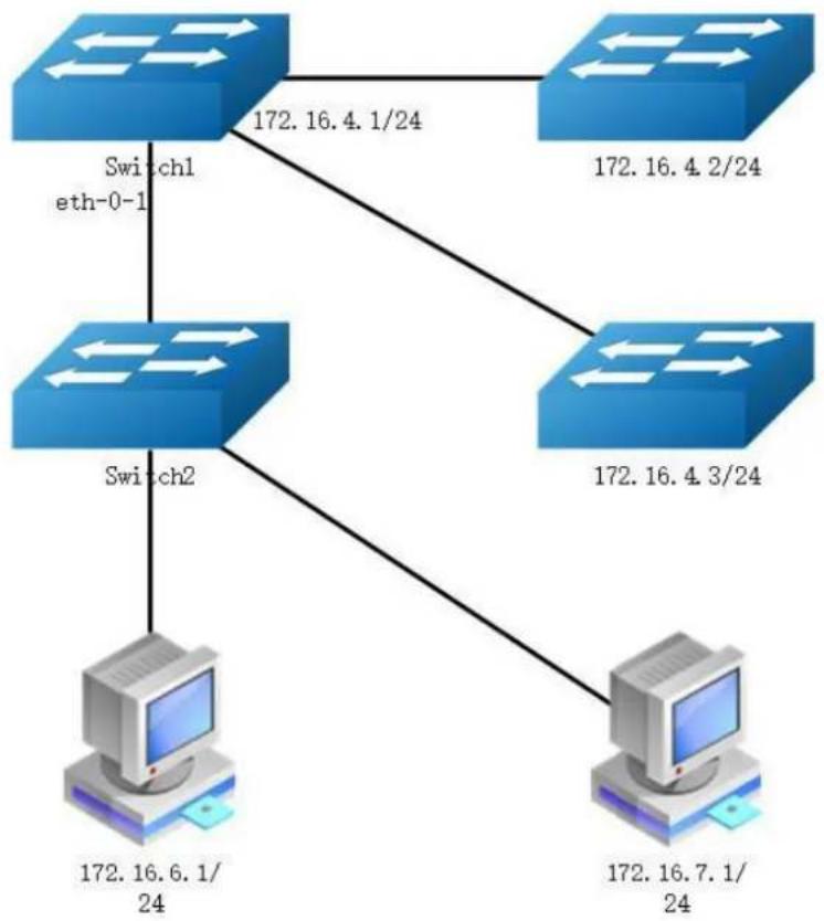
flowchart
graph TD
A["Switch1 eth-0-1"] -->|172.16.4.1/24| B["Switch2"]
C["Switch2"] -->|172.16.4.3/24| D["Computer"]
E["Switch2"] -->|172.16.7.1/24| F["Computer"]
B -->|172.16.6.1/24| G["Computer"]
D -->|172.16.4.2/24| H["Computer"]
Figure 5-17 pbr
The figure above is a typical topology: After Enabling PBR on interface eth-0-1 of Switch1, packets from 172.16.6.1 should be forwarded to 172.16.4.2, and other packets should be forwarded according to the original routes.
Configure on Switch1:
step 1 Enter the configure mode
Switch# configure terminal
step 2 Create an ip access list to match source ip address
Switch(config)# ip access-list acl1 Switch(config-ip-acl)# 10 permit any 172.16.6.0 0.0.0.255 any Switch(config-ip-acl)# exit
step 3 Create a route map, to match the ip access list and set the nexthop ip
Switch(config)# route-map rmap permit 10
Switch(config-route-map)# match ip address acl1
Switch(config-route-map)# set ip next-hop 172.16.4.2
Switch(config-route-map)# exit
step 4 Enter the interface configure mode, set the attributes and ip address, and apply the route map
Switch(config)# interface eth-0-1
Switch(config-if)# no switchport
Switch(config-if)# ip address 172.16.5.2/24
Switch(config-if)# no shutdown
Switch(config-if)# ip policy route-map rmap
Switch(config-if)# exit
step 5 Create a static route with the nexthop ip 172.16.4.3 (optional)
To forwarding the packets which not hit the PBR, we can use a static route. Dynamic protocols such as RIP/OSPF are can also meet this requirement.
Switch(config)# ip route 0.0.0.0/0 172.16.4.3
step 6 Exit the configure mode
Switch(config)# end
step 7 Validation
Switch# show ip policy route-map
Route-map interface
rmap eth-0-1
Configure PBR and BFD linkage
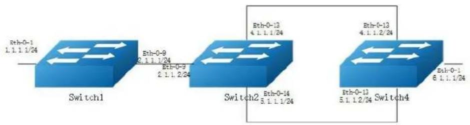
flowchart
graph LR
A["Switch1"] -->|Eth-0-9 2.1.1.1/24| B["Switch2"]
B -->|Eth-0-13 4.1.1.1/24| C["Switch4"]
C -->|Eth-0-1 6.1.1.1/24| D["Output"]
style A fill:#333,stroke:#fff,color:#fff
style B fill:#333,stroke:#fff,color:#fff
style C fill:#333,stroke:#fff,color:#fff
linkStyle 0 stroke:#000,stroke-width:2px
linkStyle 1 stroke:#000,stroke-width:2px
linkStyle 2 stroke:#000,stroke-width:2px
linkStyle 3 stroke:#000,stroke-width:2px
linkStyle 4 stroke:#000,stroke-width:2px
Figure 5-18 pbr
The figure above is a typical topology: Switch2 will forward packet to eth-0-13 according PBR routes, when Switch4 eth-0-13 shutdown, bfd session statues will be down, then track 1 will be down, and the PBR next-hop 4.1.1.2 will be invalid, packet will forward to eth-0-14.
step 1 Configure on Switch1:
Switch1# configure terminal
Switch1(config)# interface eth-0-1
Switch1(config-if)# no shutdown
Switch1(config-if)# no switchport
Switch1(config-if)# ip address 1.1.1.1/24
Switch1(config-if)# interface eth-0-9
Switch1(config-if)# no shutdown
Switch1(config-if)# no switchport
Switch1(config-if)# ip address 2.1.1.1/24
Switch1(config-if)# quit
Switch1(config)# ip route 5.1.1.0/24 2.1.1.2
Switch1(config)# ip route 6.1.1.0/24 2.1.1.2
step 2 Configure on Switch2:
Switch2# configure terminal
Switch2(config)# ip access-list acl1
Switch2(config-ip-acl)# 10 permit any host 2.1.1.1 any
Switch2(config-ip-acl)# quit
Switch2(config)# route-map rmap permit 10
Switch2(config-route-map)# match ip address acl1
Switch2(config-route-map)# set ip next-hop 4.1.1.2 track 1
Switch2(config-route-map)# quit
Switch2(config)# interface eth-0-9
Switch2(config-if)# no shutdown
Switch2(config-if)# no switchport
Switch2(config-if)# ip address 2.1.1.2/24
Switch2(config-if)# ip policy route-map rmap
Switch2(config-if)# interface eth-0-13
Switch2(config-if)# no shutdown
Switch2(config-if)# no switchport
Switch2(config-if)# ip address 4.1.1.1/24
Switch2(config-if)# interface eth-0-14
Switch2(config-if)# no shutdown
Switch2(config-if)# no switchport
Switch2(config-if)# ip address 5.1.1.1/24
Switch2(config-if)# quit
Switch2(config)# track 1 bfd source interface eth-0-13 destination 4.1.1.2
Switch2(config-track)# quit
Switch2(config)# ip route 1.1.1.0/24 2.1.1.1
Switch2(config)# ip route 6.1.1.0/24 5.1.1.2
step 3 Configure on Switch4:
Switch4# configure terminal
Switch4(config)# interface eth-0-1
Switch4(config-if)# no shutdown
Switch4(config-if)# no switchport
Switch4(config-if)# ip address 6.1.1.1/24
Switch4(config-if)# interface eth-0-13
Switch4(config-if)# no shutdown
Switch4(config-if)# no switchport
Switch4(config-if)# ip address 4.1.1.2/24
Switch4(config-if)# interface eth-0-14
Switch4(config-if)# no shutdown
Switch4(config-if)# no switchport
Switch4(config-if)# ip address 5.1.1.2/24
Switch4(config-if)# quit
Switch4(config)# track 1 bfd source interface eth-0-13 destination 4.1.1.1
Switch4(config-track)# quit
Switch4(config)# ip route 1.1.1.0/24 5.1.1.1
Switch4(config)# ip route 2.1.1.0/24 5.1.1.1
step 3 ping 6.1.1.1 Switch2 will forward packet to eth-0-13
Switch1# ping 6.1.1.1
PING 6.1.1.1 (6.1.1.1) 56(84) bytes of data.
64 bytes from 6.1.1.1: icmp_seq=1 ttl=63 time=417 ms
64 bytes from 6.1.1.1: icmp_seq=2 ttl=63 time=428 ms
64 bytes from 6.1.1.1: icmp_seq=3 ttl=63 time=441 ms
64 bytes from 6.1.1.1: icmp_seq=4 ttl=63 time=469 ms
64 bytes from 6.1.1.1: icmp_seq=5 ttl=63 time=461 ms
--- 6.1.1.1 ping statistics ---
5 packets transmitted, 5 received, 0% packet loss, time 6810ms
rtt min/avg/max/mdev = 417.834/443.810/469.720/19.470 ms
step 4 shutdown eth-0-13 of Switch4
Switch4# configure terminal
Switch4(config)# interface eth-0-13
Switch4(config-if)# shutdown
step 5 Validation
Switch2# show track
Track 1
Type : BFD state
Source interface : eth-0-13
Destination IP : 4.1.1.2
BFD Local discr : 8192
rmap : pref 10 track 1
State : down
Switch2# show bfd session
Abbreviation:
LD: Local Discriminator. RD: Remote Discriminator
S: Single hop session. M: Multi hop session.
SD: Static Discriminator. DD: Dynamic Discriminator
SBFD: Seamless BFD
A: Admin down. D:Down. I:Init. U:Up.
Lind RD TYPE ST UP-Time Remote-Addr Sbfd-Type VRF
8192 0 S-DD D 00:00:00 4.1.1.2 None default
Number of Sessions: 1
Switch2 will forward packet to eth-0-14
Switch# ping 6.1.1.1
PING 6.1.1.1 (6.1.1.1) 56(84) bytes of data.
64 bytes from 6.1.1.1: icmp_seq=1 ttl=63 time=414 ms
64 bytes from 6.1.1.1: icmp_seq=2 ttl=63 time=432 ms
64 bytes from 6.1.1.1: icmp_seq=3 ttl=63 time=424 ms
64 bytes from 6.1.1.1: icmp_seq=4 ttl=63 time=525 ms
64 bytes from 6.1.1.1: icmp_seq=5 ttl=63 time=437 ms
--- 6.1.1.1 ping statistics ---
5 packets transmitted, 5 received, 0% packet loss, time 6563ms
rtt min/avg/max/mdev = 414.720/446.816/525.276/39.949 ms
5.6.3 Application cases
N/A
5.7 Configuring BGP
5.7.1 Overview
Function Introduction
The Border Gateway Protocol (BGP) is an inter-Autonomous System routing protocol.
The primary function of a BGP speaking system is to exchange network reachability information with other BGP systems. This network reachability information includes information on the list of Autonomous Systems (ASes) that reachability information traverses. This information is sufficient for constructing a graph of AS connectivity for this reachability, from which routing loops may be pruned and, at the AS level, some policy decisions may be enforced.
BGP-4 provides a set of mechanisms for supporting Classless Inter-Domain Routing (CIDR) [RFC1518, RFC1519]. These mechanisms include support for advertising a set of destinations as an IP prefix and eliminating the concept of network “class” within BGP. BGP-4 also introduces mechanisms that allow aggregation of routes, including aggregation of AS paths.
Routing information exchanged via BGP supports only the destination-based forwarding paradigm, which assumes that a router forwards a packet based solely on the destination address carried in the IP header of the packet. This, in turn, reflects the set of policy decisions that can (and cannot) be enforced using BGP. BGP can support only those policies conforming to the destination-based forwarding paradigm.
Principle Description
For more BGP information please reference [RFC 1771, RFC 4271].
5.7.2 Configuration
Configure EBGP
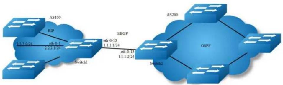
flowchart
graph LR
A["AS100"] -->|RIP 3.3.3.0/24| B["Switch1"]
B -->|eth-0-1 2.2.2.1/24| C["EBGP"]
C -->|eth-0-13 1.1.1.1/24| D["OSPF"]
D -->|eth-0-13 1.1.1.2/24| E["Switch2"]
E --> F["AS200"]
Figure 5-19 EBGP
step 1 Enter the configure mode
Switch# configure terminal
step 2 Enter the interface configure mode and set the attributes
Switch1:
Switch(config)# interface eth-0-13 Switch(config-if)# no shutdown
Switch(config-if)# no switchport
Switch(config-if)# ip address 1.1.1.1/24
Switch(config-if)# exit
Switch(config)# interface eth-0-1
Switch(config-if)# no shutdown
Switch(config-if)# no switchport
Switch(config-if)# ip address 2.2.2.1/24
Switch(config-if)# exit
Switch2:
Switch(config)# interface eth-0-13
Switch(config-if)# no shutdown
Switch(config-if)# no switchport
Switch(config-if)# ip address 1.1.1.2/24
Switch(config-if)# exit
step 3 Configure a static route
Switch1:
Switch(config)# ip route 3.3.3.0/24 2.2.2.2
step 4 Configure the Routing process and set the router id, set the neighbor, associate the network, and set the redistribute attributes
Switch1:
Switch(config)# router bgp 100
Switch(config-router)# bgp router-id 10.10.10.10
Switch(config-router)# neighbor 1.1.1.2 remote-as 200
Switch(config-router)# neighbor 1.1.1.2 ebgp-multihop
Switch(config-router)# network 4.0.0.0/8
Switch(config-router)# redistribute static
Switch(config-router)# redistribute connected
Switch(config-router)# exit
Switch2:
Switch(config)# router bgp 200
Switch(config-router)# bgp router-id 11.11.11.11
Switch(config-router)# neighbor 1.1.1.1 remote-as 100
Switch(config-router)# neighbor 1.1.1.1 ebgp-multihop
Switch(config-router)# redistribute connected
Switch(config-router)# exit
step 5 Exit the configure mode
Switch(config)# end
step 6 Validation
Switch1:
Switch# show ip bgp neighbors
BGP neighbor is 1.1.1.2, remote AS 200, local AS 100, external link
BGP version 4, remote router ID 0.0.0.0
BGP state = Active
Last read 00:26:00, hold time is 180, keepalive interval is 60 seconds
Received 0 messages, 0 notifications, 0 in queue
Sent 0 messages, 0 notifications, 0 in queue
Route refresh request: received 0, sent 0
Minimum time between advertisement runs is 30 seconds
For address family: IPv4 Unicast
BGP table version 1, neighbor version 0
Index 1, Offset 0, Mask 0x2
0 accepted prefixes
0 announced prefixes
Connections established 0; dropped 0
External BGP neighbor may be up to 255 hops away.
Next connect timer due in 87 seconds
Switch2:
SwitchB# show ip bgp neighbors
BGP neighbor is 1.1.1.1, remote AS 100, local AS 200, external link
BGP version 4, remote router ID 0.0.0.0
BGP state = Active
Last read 00:21:39, hold time is 180, keepalive interval is 60 seconds
Received 0 messages, 0 notifications, 0 in queue
Sent 0 messages, 0 notifications, 0 in queue
Route refresh request: received 0, sent 0
Minimum time between advertisement runs is 30 seconds
For address family: IPv4 Unicast
BGP table version 1, neighbor version 0
Index 1, Offset 0, Mask 0x2
0 accepted prefixes
0 announced prefixes
Connections established 0; dropped 0
External BGP neighbor may be up to 255 hops away.
Next connect timer due in 97 seconds
Configure IBGP
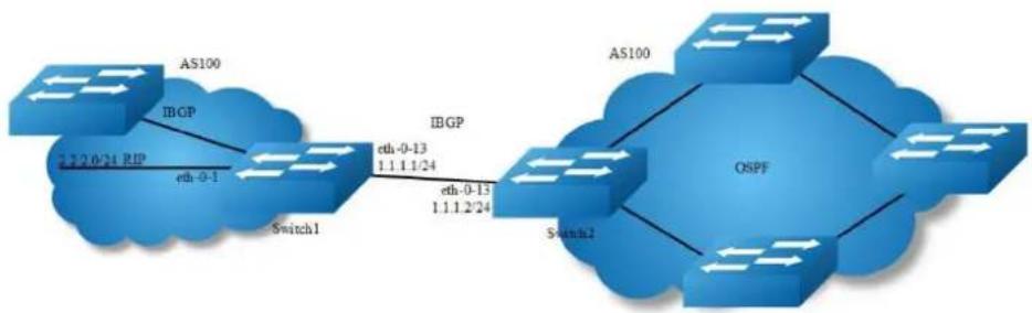
flowchart
graph LR
A["AS100"] -->|IBGP| B["Switch1"]
B -->|eth-0-1| C["2.2.0/24 RIP"]
C -->|Eth-0-13 1.1.1.2/24| D["OSPF"]
D -->|Eth-0-13 1.1.1.2/24| E["Switch2"]
E --> F["AS100"]
Figure 5-20 IBGP
step 1 Enter the configure mode
Switch# configure terminal
step 2 Enter the interface configure mode and set the attributes
Switch1:
Switch(config)# interface eth-0-1
Switch(config-if)# no shutdown
Switch(config-if)# no switchport
Switch(config-if)# ip address 2.2.2.1/24
Switch(config-if)# exit
Switch(config)# interface eth-0-13
Switch(config-if)# no shutdown
Switch(config-if)# no switchport
Switch(config-if)# ip address 1.1.1.1/24
Switch(config-if)# exit
Switch(config)#interface loopback 0
Switch(config-if)# ip address 10.10.10.10/32
Switch(config-if)# exit
Switch2:
Switch(config)# interface eth-0-13
Switch(config-if)# no shutdown
Switch(config-if)# no switchport
Switch(config-if)# ip address 1.1.1.2/24
Switch(config-if)# exit
Switch(config)# interface loopback 0
Switch(config-if)# ip address 11.11.11.11/32
Switch(config-if)# exit
step 3 Configure a static route
Switch1:
step 4 Configure the Routing process and set the router id, set the neighbor, associate the network, and set the redistribute attributes
Switch1:
Switch(config)# router bgp 100
Switch(config-router)# bgp router-id 10.10.10.10
Switch(config-router)# neighbor 11.11.11.11 remote-as 100
Switch(config-router)# neighbor 11.11.11.11 update-source loopback 0
Switch(config-router)# network 4.0.0.0/8
Switch(config-router)# redistribute static
Switch(config-router)# redistribute connected
Switch(config-router)# exit
Switch2:
Switch(config)# router bgp 100
Switch(config-router)# bgp router-id 11.11.11.11
Switch(config-router)# neighbor 10.10.10.10 remote-as 100
Switch(config-router)# neighbor 10.10.10.10 update-source loopback 0
Switch(config-router)# redistribute connected
Switch(config-router)# exit
step 5 Exit the configure mode
Switch(config)# end
step 6 Validation
Switch1:
Switch# show ip bgp neighbors
BGP neighbor is 11.11.11.11, remote AS 100, local AS 100, internal link
BGP version 4, remote router ID 0.0.0.0
BGP state = Active
Last read 00:02:32, hold time is 180, keepalive interval is 60 seconds
Received 0 messages, 0 notifications, 0 in queue
Sent 0 messages, 0 notifications, 0 in queue
Route refresh request: received 0, sent 0
Minimum time between advertisement runs is 5 seconds
Update source is loopback0
For address family: IPv4 Unicast
BGP table version 1, neighbor version 0
Index 1, Offset 0, Mask 0x2
0 accepted prefixes
0 announced prefixes
Connections established 0; dropped 0
Next connect timer due in 62 seconds
Switch2:
Switch# show ip bgp neighbors
BGP neighbor is 10.10.10.10, remote AS 100, local AS 100, internal link
BGP version 4, remote router ID 0.0.0.0
BGP state = Active
Last read 00:01:58, hold time is 180, keepalive interval is 60 seconds
Received 0 messages, 0 notifications, 0 in queue
Sent 0 messages, 0 notifications, 0 in queue
Route refresh request: received 0, sent 0
Minimum time between advertisement runs is 5 seconds
Update source is loopback0
For address family: IPv4 Unicast
BGP table version 1, neighbor version 0
Index 1, Offset 0, Mask 0x2
0 accepted prefixes
0 announced prefixes
Connections established 0; dropped 0
Next connect timer due in 17 seconds
5.7.3 Application cases
N/A
5.8 Configuring ISIS
5.8.1 Overview
Function Introduction
Intermediate System to Intermediate System(ISIS) is a link state routing protocol that uses the shortest path first (SPF) algorithm for routing algorithms. It is actually very similar to OSPF. It also uses Hello protocol to find neighboring nodes and uses a propagation protocol to send link information. ISIS can operate on different subnets, including broadcast LANs, WANs and point-to-point links.
Principle Description
NET
The Network Entity Title (NET) indicates the network layer information of the IS itself, excluding the transport layer information (SEL = 0). It can be regarded as a special kind of NSAP, that is, an NSAP address whose SEL is 0. Therefore, NET is the same length as NSAP, with a maximum of 20 bytes and a minimum of 8 bytes. Generally, a router can be configured with a NET. When an area needs to be re-
divided, for example, multiple areas are combined, or an area is divided into multiple areas. In this case, multiple NETs can be configured during reconfiguration Still can guarantee the correctness of the route. As a router default can be configured up to three regional addresses, so up to only three NET configuration. When configuring multiple NETs, you must ensure that their System IDs are the same. For example, NET is: ab.cdef.1234.5678.9abc.00, where Area is ab.cdef, System ID is 1234.5678.9abc, and SEL is 00.
ISIS area
- Two-level structure In order to support large-scale routing networks, IS-IS adopts a two-level hierarchical structure in the routing domain. A large routing domain is divided into one or more Areas. Routes in the area are managed by Level-1 routers and inter-area routes are managed by Level-2 routers.
• Level-1 and Level-2
Level-1 router The Level-1 router is responsible for the intra-area routing. It only establishes the neighbor relationship with the Level-1 and Level-1-2 routers in the same area and maintains a Level-1 LSDB. The Level-1 router contains the routing information of the area. The packet is forwarded to the nearest Level-1-2 router.
Level-2 router The Level-2 router is responsible for inter-area routing. It can establish the neighbor relationship with Level-2 and Level-1-2 routers in the same area or other areas and maintains a Level-2 LSDB. The LSDB contains inter-area routing information. All Level-2 routers and Level-1-2 routers form the backbone network in the routing domain and are responsible for communication between different areas. The Level-2 routers in the routing domain must be physically contiguous to ensure continuity of the backbone network. Only Level-2 routers can exchange data packets or routing information with routers outside the routing domain.
Level-1-2 router Routers belonging to Level-1 and Level-2 are called Level-1-2 routers. They can establish Level-1 neighbor relationships with Level-1 and Level-1-2 routers in the same area or with Level-1 routers in the same area or with other areas Level-2 and Level-1-2 routers form a Level-2 neighbor relationship. Level-1 routers must pass through Level-1-2 routers to connect to other areas. The Level-1-2 router maintains two LSDBs. The Level-1 LSDB is used for intra-area routing. The Level-2 LSDB is used for inter-area routing.
- The route type of the interface For a router of type Level-1-2, you may need to set up Level-1 adjacency with only one peer and establish only Level-2 adjacency with the other peer. You can set the routing layer type of the corresponding interface to limit the adjacencies that can be established on the interface. For example, Level-1 interfaces can only establish Level-1 adjacencies. Level-2 interfaces can only establish Level-2 adjacencies. For Level-1-2 routers, you can also save bandwidth by preventing Level-1 Hello packets from being sent to the Level-2 backbone network by configuring some interfaces as Level-2.
- Route infiltration (Route Leaking) Generally, an IS-IS area is also called a Level-1 area. Routes in the area are managed by Level-1 routers. All Level-2 routers form a Level-2 area. Therefore, an IS-IS routing domain can contain multiple Level-1 areas but only one Level-2 area.
5.8.2 Configuration
Basic ISIS Parameters Configuration
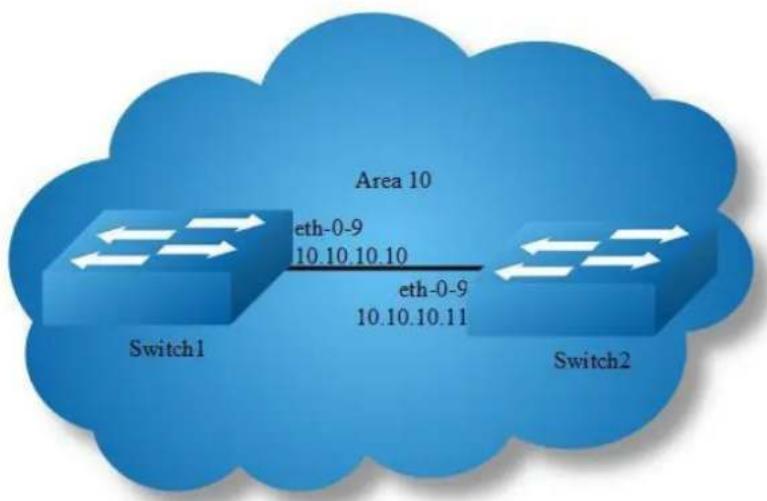
Figure 5-21 RIPng
step 1 Enter the configure mode
Switch# configure terminal
step 2 Configure the Routing process and set the net
configuration for Switch1:
Switch(config)# router isis
Switch(config-router)# net 10.0000.0000.0001.00
Switch(config-router)# exit
configuration for Switch2:
Switch(config)# router isis
Switch(config-router)# net 10.0000.0000.0002.00
Switch(config-router)# exit
step 3 Enable ipv4 isis on the interface
configuration for Switch1:
Switch(config)# interface eth-0-9
Switch(config-if)# no switchport
Switch(config-if)# ip address 10.10.10.10/24
Switch(config-if)# ip router isis
Switch(config)# interface loopback 0
Switch(config-if)# ip address 1.1.1.1/32
Switch(config-if)# ip router isis
configuration for Switch2:
Switch(config)# interface eth-0-9
Switch(config-if)# no switchport
Switch(config-if)# ip address 10.10.10.11/24
Switch(config-if)# ip router isis
Switch(config)# interface loopback 0
Switch(config-if)# ip address 2.2.2.2/32
Switch(config-if)# ip router isis
step 4 Validation
Display the result on Switch1:
Switch# show clns neighbors
Area (null):
System Id Interface SNPA State Holdtime Type Protocol
0000.0000.0002 eth-0-9 4a98.a825.3d00 Up 21 L1 IS-IS
Up 21 L2 IS-IS
Switch# show isis database verbose
Area (null):
IS-IS Level-1 Link State Database:
LSPID LSP Seq Num LSP Checksum LSP Holdtime ATT/P/OL
0000.0000.0001.00-00* 0x00000004 0x3244 1082 0/0/0
Area Address: 10
NLPID: IPV4
IP Address: 10.10.10.10
Metric: 10 IS 0000.0000.0001.01
Metric: 10 IP 10.10.10.0 255.255.255.0
Metric: 10 IP 1.1.1.1 255.255.255.255
0000.0000.0001.01-00* 0x00000001 0x21B9 895 0/0/0
Metric: 0 IS 0000.0000.0001.00
Metric: 0 IS 0000.0000.0002.00
0000.0000.0002.00-00 0x00000004 0xFA75 1076 0/0/0
Area Address: 10
NLPID: IPV4
IP Address: 10.10.10.11
Metric: 10 IS 0000.0000.0001.01
Metric: 10 IP 10.10.10.0 255.255.255.0
Metric: 10 IP 2.2.2.2 255.255.255.255
IS-IS Level-2 Link State Database:
LSPID LSP Seq Num LSP Checksum LSP Holdtime ATT/P/OL
0000.0000.0001.00-00* 0x00000005 0xFCCE 1109 0/0/0
Area Address: 10
NLPID: IPV4
IP Address: 10.10.10.10
Metric: 10 IS 0000.0000.0001.01
Metric: 10 IP 10.10.10.0 255.255.255.0
Metric: 20 IP 2.2.2.2 255.255.255.255
Metric: 10 IP 1.1.1.1 255.255.255.255
0000.0000.0001.01-00* 0x00000001 0x21B9 895 0/0/0
Metric: 0 IS 0000.0000.0001.00
Metric: 0 IS 0000.0000.0002.00
OOOO.OOOO.OOOO.OOOO.OOOO.OOOO.OOOO.OOOO.OOOO.OOOO.OOOO.OOOO.OOOO.OOOO.OOOO.OOOO.OOOO.OOOO.OOOO.OOOO.OOOO.OOOO.OOOO.OOOO.OOOO.OOOO.OOOO.OOOO.OOOO.OOOO.OOOO.OOOO.OOOO.OOOO.Ooo
Area Address: 10
NLPID: IPV4
IP Address: 10.10.10.11
Metric: 10 IS 00U.O.O.O.O.O.O.O.O.O.O.O.O.O.O.O.O.O.O.O.O.O.O.O.O.O.O.O.O.O.O.O.O.O.O.O.O.O.O.O.O.O.O.O.O.O.O.O.O.O.O.O.O.O.O.O.O.O.O.O.O.O.O.O.O.O.O.O.O.O.O.C
Switch# show ip isis route
Codes: C - connected, E - external, L1 - IS-IS level-1, L2 - IS-IS level-2 ia - IS-IS inter area, D - discard, e - external metric
Area (null):
Destination Metric Next-Hop Interface Tag
C 1.1.1.1/32 1D -- loopbacko O
Ll 2.2.2.2/32 2D 1D 1D 1D 1D 1D 1D 1D
C 1D 1D -- eth-9 O
Display the result on Switch2:
Switch# show clns neighbors
Area (null):
System Id Interface SNPA State Holdtime Type Protocol
0000.0000.0001 eth-0-9 a821.1873.ae00 Up 9 L1 IS-IS
Up 9 L2 IS-IS
Switch# show isis database verbose
Area (null):
IS-IS Level-1 Link State Database:
LSPID LSP Seq Num LSP Checksum LSP Holdtime ATT/P/OL
0000.0000.0001.00-00 0x00000004 0x3244 934 0/0/0
Area Address: 10
NLPID: IPV4
IP Address: 10.10.10.10
Metric: 10 IS 0000.0000.0001.01
Metric: 10 IP 10.10.10.0 255.255.255.0
Metric: 10 IP 1.1.1.1 255.255.255.255
0000.0000.0001.01-00 0x00000001 0x21B9 745 0/0/0
Metric: 0 IS 0000.0000.0001.00
Metric: 0 IS 0000.0000.0002.00
0000.0000.0002.00-00* 0x00000004 0xFA75 930 0/0/0
Area Address: 10
NLPID: IPV4
IP Address: 10.10.10.11
Metric: 10 IS 0000.0000.0001.01
Metric: 10 IP 10.10.10.0 255.255.255.0
Metric: 10 IP 2.2.2.2 255.255.255.255
IS-IS Level-2 Link State Database:
LSPID LSP Seq Num LSP Checksum LSP Holdtime ATT/P/OL
0000.0000.0001.00-00 0x00000005 0xFCCE 961 0/0/0
Area Address: 10
NLPID: IPV4
IP Address: 10.10.10.10
Metric: 10 IS 0000.0000.0001.01
Metric: 10 IP 10.10.10.0 255.255.255.0
Metric: 20 IP 2.2.2.2 255.255.255.255
Metric: 10 IP 1.1.1.1 255.255.255.255
0000.0000.0001.01-00 0x00000001 0x21B9 747 0/0/0
Metric: 0 IS 0000.0000.0001.00
Metric: 0 IS 0000.0000.0002.00
0000.0000.0002.00-00* 0x00000005 0x7B4E 960 0/0/0
Area Address: 10
NLPID: IPV4
IP Address: 10.10.10.11
Metric: 10 IS 0000.0000.0001.01
Metric: 10 IP 10.10.10.0 255.255.255.0
Metric: 10 IP 2.2.2.2 255.255.255.255
Metric: 20 IP 1.1.1.1 255.255.255.255
Switch# show ip isis route
Codes: C - connected, E - external, L1 - IS-IS level-1, L2 - IS-IS level-2
ia - IS-IS inter area, D - discard, e - external metric
Area (null):
Destination Metric Next-Hop Interface Tag
L1 1.1.1.1/32 20 10.10.10.10 eth-0-9 0
C 2.2.2.2/32 10 -- loopback0 0
C 10.10.10.0/24 10 -- eth-0-9 0
5.8.3 Application cases
N/A
6 Multicast Configuration Guide
6.1 Configuring IP Multicast-Routing
6.1.1 Overview
Function Introduction
Multicast protocols allow a group or channel to be accessed over different networks by multiple stations (clients) for the receipt and transmit of multicast data.
Distribution of stock quotes, video transmissions such as news services and remote classrooms, and video conferencing are all examples of applications that use multicast routing.
Internet Group Management Protocol (IGMP) is used among hosts on a LAN and the routers (and multilayer switches) on that LAN to track the multicast groups of which hosts are members.
Protocol-Independent Multicast (PIM) protocol is used among routers and multilayer switches to track which multicast packets to forward to each other and to their directly connected LANs. PIM has two modes: Sparse-mode and Dense-mode.
Principle Description
N/A
6.1.2 Configuration
Configuring multicast route limit
step 1 Enter the configure mode
Switch# configure terminal
step 2 set the limit of the multicast route
Switch(config)# ip multicast route-limit 1000
step 3 Exit the configure mode
Switch(config)# end
step 4 Validation
Switch# show ip mroute route-limit Max Multicast Route Limit Number: 1000 Multicast Route Limit Warning Threshold: 1000 Multicast Hardware Route Limit: 1023 Current Multicast Route Entry Number: 0
6.1.3 Application cases
N/A
6.2 Configuring IGMP
6.2.1 Overview
Function Introduction
To participate in IP multicasting, multicast hosts, routers, and multilayer switches must have the IGMP operating. This protocol defines the querier and host roles:
A querier is a network device that sends query messages to discover which network devices are members of a given multicast group.
A host is a receiver that sends report messages (in response to query messages) to inform a querier of a host membership.
A set of queries and hosts that receive multicast data streams from the same source is called a multicast group. Queriers and hosts use IGMP messages to join and leave multicast groups. - Any host, regardless of whether it is a member of a group, can send to a group. However, only the members of a group receive the message. Membership in a multicast group is dynamic; hosts can join and leave at any time. There is no restriction on the location or number of members in a multicast group.
A host can be a member of more than one multicast group at a time. How active a multicast group is and what members it has can vary from group to group and from time to time. A multicast group can be active for a long time, or it can be very short-lived. Membership in a group can constantly change. A group that has members can have no activity.
IGMP packets are sent using these IP multicast group addresses:
IGMP general queries are destined to the address 224.0.0.1 (all systems on a subnet).
IGMP group-specific queries are destined to the group IP address for which the switch is querying.
IGMP group membership reports are destined to the group IP address for which the switch is reporting.
IGMP Version 2 (IGMPv2) leave messages are destined to the address 224.0.0.2 (all-multicast-routers on a subnet). In some old host IP stacks, leave messages might be destined to the group IP address rather than to the all-routers address.
Principle Description
Reference to RFC 1112, RFC 2236, RFC 3376
6.2.2 Configuration
There is no explicit command to enable IGMP, which is always combined with PIM-SM. When PIM-SM is enabled on an interface, IGMP will be enabled automatically on this interface, vice versa. But notice, before IGMP can work, IP Multicast-routing
must be enabled globally firstly. We support build IGMP group record by learning IGMP packets or configuring static IGMP group by administrator.
step 1 Enter the configure mode
Switch# configure terminal
step 2 Enable ip multicast-routing globally
Switch(config)# ip multicast-routing
step 3 Enter the interface configure mode, set the attributes and ip address
Switch(config)# interface eth-0-1
Switch(config-if)# no switchport
Switch(config-if)# ip address 10.10.10.10/24
Switch(config-if)# exit
Switch(config)# interface eth-0-2
Switch(config-if)# no switchport
Switch(config-if)# ip address 10.10.11.10/24
Switch(config-if)# exit
step 4 Enable pim-sm on the interface
Switch(config)# interface eth-0-1
Switch(config-if)# ip pim sparse-mode
Switch(config-if)# exit
Switch(config)# interface eth-0-2
Switch(config-if)# ip pim sparse-mode
Switch(config-if)# exit
step 5 Set the attributes for igmp
Switch(config)# interface eth-0-1
Switch(config-if)# ip igmp version 2
Switch(config-if)# ip igmp query-interval 120
Switch(config-if)# ip igmp query-max-response-time 12
Switch(config-if)# ip igmp robustness-variable 3
Switch(config-if)# ip igmp last-member-query-count 3
Switch(config-if)# ip igmp last-member-query-interval 2000
Switch(config-if)# exit
step 6 Set the maximum igmp group count(optional)
The maximum igmp group count is limited globally or per-interface.
Switch(config)# ip igmp limit 2000
Switch(config)# interface eth-0-1
Switch(config-if)# ip igmp limit 1000
step 7 Set a static igmp group
Switch(config-if)# ip igmp static-group 228.1.1.1
Switch(config-if)# exit
step 8 Set igmp proxy(optional)
Switch(config)# interface eth-0-1
Switch(config-if)# ip igmp proxy-service
Switch(config-if)# exit
Switch(config)# interface eth-0-2
Switch(config-if)# ip igmp mroute-proxy eth-0-1
Switch(config-if)# exit
step 9 Exit the configure mode
Switch(config)# end
step 10 Validation
Use the following command to display the information of igmp interfaces:
Switch# show ip igmp interface
Interface eth-0-1 (Index 1)
IGMP Inactive, Version 2 (default) proxy-service
IGMP host version 2
IGMP global limit is 2000
IGMP global limit states count is currently 0
IGMP interface limit is 1000
IGMP interface has 0 group-record states
IGMP activity: 0 joins, 0 leaves
IGMP query interval is 120 seconds
IGMP querier timeout is 366 seconds
IGMP max query response time is 12 seconds
Last member query response interval is 2000 milliseconds
Group Membership interval is 372 seconds
Last memeber query count is 3
Robustness Variable is 3
Interface eth-0-2 (Index 2)
IGMP Inactive, Version 2 (default)
IGMP mroute-proxy interface is eth-0-1
IGMP global limit is 2000
IGMP global limit states count is currently 0
IGMP interface limit is 16384
ICMP interface has 0 group-record states
IGMP activity: 0 joins, 0 leaves
IGMP query interval is 125 seconds
IGMP querier timeout is 255 seconds
ICMP max query response time is 10 seconds
Last member query response interval is 1000 milliseconds
Group Membership interval is 260 seconds
Last memeber query count is 2
Robustness Variable is 2
Use the following command to display the information of groups:
Switch# show ip igmp groups
IGMP Connected Group Membership
Group Address Interface Uptime Expires Last Reporter
228.1.1.1 eth-0-1 00:00:05 stopped -
6.2.3 Application cases
N/A
6.3 Configuring PIM-SM
6.3.1 Overview
Function Introduction
The Protocol Independent Multicasting-Sparse Mode (PIM-SM) is a multicast routing protocol designed to operate efficiently across Wide Area Networks (WANs) with sparsely distributed groups. It helps network nodes that are geographically dispersed to conserve bandwidth, and reduces traffic by simultaneously delivering a single stream of information to multiple locations.
PIM-SM uses the IP multicast model of receiver-initiated membership, supporting both shared and shortest-path trees, and uses soft-state mechanisms to adapt to changing network conditions. It relies on a topology-gathering protocol to populate a multicast routing table with routes.
Principle Description
The PIM-SM module is based on the following IETF standard: RFC 4601
Terminology:
Rendezvous Point (RP): A Rendezvous Point (RP) router is configured as the root of the non-source-specific distribution tree for a multicast group. Join
messages from receivers for a group are sent towards the RP. Data from senders is sent to the RP so that receivers can discover who the senders are, and receive traffic destined for the group.
Multicast Routing Information Base (MRIB): The MRIB is a multicast topology table derived from the unicast routing table. In PIM-SM, the MRIB is used to decide where to send Join/Prune messages. It also provides routing metrics for destination addresses. These metrics are used when sending and processing Assert messages.
Reverse Path Forwarding: Reverse Path Forwarding (RPF) is a concept of an optimized form of flooding, where the router accepts a packet from SourceA through Interface IF1 only if IF1 is the interface the router would use in order to reach SourceA. It determines whether the interface is correct by consulting its unicast routing tables. The packet that arrives through interface IF1 is forwarded because the routing table lists this interface as the shortest path to the network. The router's unicast routing table determines the shortest path for the multicast packets. Because a router accepts a packet from only one neighbor, it floods the packet only once, meaning that (assuming point-to-point links) each packet is transmitted over each link once in each direction.
Tree Information Base (TIB): The TIB is the collection of state at a PIM router storing the state of all multicast distribution trees at that router. It is created by receiving Join/Prune messages, Assert messages, and IGMP information from local hosts.
Upstream: Towards to root of the tree. The root of the tree might be either the Source or the RP.
Downstream: Away from the root of the tree. The root of tree might be either the Source or the RP.
Source-Based Trees: In the Source-Based Trees concept, the forwarding paths are based on the shortest unicast path to the source. If the unicast routing metric is hop counts, the branches of the multicast Source-Based Trees are minimum hop. If the metric is delay, the branches are minimum delay. For every multicast source, there is a corresponding multicast tree that directly connects the source to all receivers. All traffic to the members of an associated group passes along the tree made for their source. Source-Based Trees have two entries with a list of outgoing interfaces- the source address and the multicast group.
Shared Trees: Shared trees or RP trees (RPT) rely on a central router called the Rendezvous Point (RP) that receives all traffic from the sources, and forwards that traffic to the receivers. All hosts might not be receivers. There is a single tree for each multicast group, regardless of the number of sources. Only the routers on the tree know about the group, and information is sent only to interested receivers. With an RP, receivers have a place to join, even if no source exists. The shared tree is unidirectional, and information flows only from the RP to the receivers. If a host other than the RP has to send data on the tree, the data must first be tunneled to the RP, and then multicast to the members. This means that even if a receiver is also a source, it can only use the tree to receive packets from the RP, and not to send packets to the RP (unless the source is located between the RP and the receivers).
Bootstrap Router (BSR): When a new multicast sender starts sending data packets, or a new receiver starts sending the Join message towards the RP for that multicast group, it needs to know the next-hop router towards the RP. The BSR provides group-to-RP mapping information to all the PIM routers in a domain, allowing them to map to the correct RP address.
Sending out Hello Messages: PIM routers periodically send Hello messages to discover neighboring PIM routers. Hello messages are multicast using the address 224.0.0.13 (ALL-PIM-ROUTERS group). Routers do not send any acknowledgement that a Hello message was received. A hold time value determines the length of time for which the information is valid. In PIM-SM, a downstream receiver must join a group before traffic is forwarded on the interface.
Electing a Designated Router: In a multi-access network with multiple routers connected, one of them is selected to act as a designated router (DR) for a given period of time. The DR is responsible for sending Join/Prune messages to the RP for local members.
Determining the RP: PIM-SM uses a Bootstrap Router (BSR) to originate Bootstrap messages, and to disseminate RP information. The messages are multicast to the group on each link. If the BSR is not apparent, the routers flood the domain with advertisements. The router with the highest priority (if priorities are same, the higher IP address applies) is selected to be the RP. Routers receive and store Bootstrap messages originated by the BSR. When a DR gets a membership indication from IGMP for (or a data packet from) a
directly connected host, for a group for which it has no entry, the DR maps the group address to one of the candidate RPs that can service that group. The DR then sends a Join/Prune message towards that RP. In a small domain, the RP can also be configured statically.
Joining the Shared Tree: To join a multicast group, a host sends an IGMP message to its upstream router, after which the router can accept multicast traffic for that group. The router sends a Join message to its upstream PIM neighbor in the direction of the RP. When a router receives a Join message from a downstream router, it checks to see if a state exists for the group in its multicast routing table. If a state already exists, the Join message has reached the shared tree, and the interface from which the message was received is entered in the Outgoing Interface list. If no state exists, an entry is created, the interface is entered in the Outgoing Interface list, and the Join message is again sent towards the RP.
Registering with the RP: A DR can begin receiving traffic from a source without having a Source or a Group state for that source. In this case, the DR has no information on how to get multicast traffic to the RP through a tree. When the source DR receives the initial multicast packet, it encapsulates it in a Register message, and unicasts it to the RP for that group. The RP decapsulates each Register message, and forwards the extracted data packet to downstream members on the RPT. Once the path is established from the source to the RP, the DR begins sending traffic to the RP as standard IP multicast packets, as well as encapsulated within Register messages. The RP temporarily receives packets twice. When the RP detects the normal multicast packets, it sends a Register-Stop message to the source DR, meaning it should stop sending register packets.
Sending Register-Stop Messages: When the RP begins receiving traffic from the source, both as Register messages and as unencapsulated IP packets, it sends a Register-Stop message to the DR. This notifies the DR that the traffic is now being received as standard IP multicast packets on the SPT. When the DR receives this message, it stops encapsulating traffic in Register messages.
Pruning the Interface: Routers attached to receivers send Prune messages to the RP to disassociate the source from the RP. When an RP receives a Prune message, it no longer forwards traffic from the source indicated in the Prune message. If all members of a multicast group are pruned, the IGMP state of the
DR is deleted, and the interface is removed from the Source and Group lists of the group.
Forwarding Multicast Packets: PIM-SM routers forward multicast traffic onto all interfaces that lead to receivers that have explicitly joined a multicast group. Messages are sent to a group address in the local subnetwork, and have a Time to Live (TTL) of 1. The router performs an RPF check, and forwards the packet. Traffic that arrives on the correct interface is sent onto all outgoing interfaces that lead to downstream receivers if the downstream router has sent a join to this router, or is a member of this group.
6.3.2 Configuration

flowchart
graph LR
subgraph Switch1
A["eth-0-1\n11.1.1.1/24"] --> B["Switch1"]
C["eth-0-9\n12.1.1.1/24"] --> D["Switch1"]
E["eth-0-9\n12.1.1.2/24"] --> F["Switch2"]
G["eth-0-1\n22.1.1.2/24"] --> H["Switch2"]
end
Figure 6-1 Pim sm
PIM-SM is a soft-state protocol. The main requirement is to enable PIM-SM on desired interfaces, and configure the RP information correctly, through static or dynamic methods. All multicast group states are maintained dynamically as the result of IGMP Report/Leave and PIM Join/Prune messages.
This section provides PIM-SM configuration examples for two relevant scenarios. The following graphic displays the network topology used in these examples:
Configuring General PIM Sparse-mode (static RP)
In this example, using the above topology, Switch1 is the Rendezvous Point (RP), and all routers are statically configured with RP information. While configuring the RP, make sure that:
Every router includes the ip pim rp-address 11.1.1.1 statement, even if it does not have any source or group member attached to it.
There is only one RP address for a group scope in the PIM domain.
All interfaces running PIM-SM must have sparse-mode enabled.
Here is a sample configuration:
step 1 Enter the configure mode
Switch# configure terminal
step 2 Enter the interface configure mode, set the attributes and ip address, and enable pim-sm
Configuring on Switch1:
Switch(config)# interface eth-0-1
Switch(config-if)# no shutdown
Switch(config-if)# no switchport
Switch(config-if)# ip address 11.1.1.1/24
Switch(config-if)# ip pim sparse-mode
Switch(config-if)# exit
Switch(config)# interface eth-0-9
Switch(config-if)# no shutdown
Switch(config-if)# no switchport
Switch(config-if)# ip address 12.1.1.1/24
Switch(config-if)# ip pim sparse-mode
Switch(config-if)# exit
Configuring on Switch2:
Switch(config)# interface eth-0-1
Switch(config-if)# no shutdown
Switch(config-if)# no switchport
Switch(config-if)# ip address 22.1.1.2/24
Switch(config-if)# ip pim sparse-mode
Switch(config-if)# exit
Switch(config)# interface eth-0-9
Switch(config-if)# no shutdown
Switch(config-if)# no switchport
Switch(config-if)# ip address 12.1.1.2/24
Switch(config-if)# ip pim sparse-mode
Switch(config-if)# exit
step 3 Add static routes
Configuring on Switch1:
Switch(config)# ip route 22.1.1.0/24 12.1.1.2
Configuring on Switch2:
Switch(config)# ip route 11.1.1.0/24 12.1.1.1
step 4 Configure the static rp address
Switch(config)# ip pim rp-address 11.1.1.1
step 5 Exit the configure mode
Switch(config)# end
step 6 Validation
Use the following command to show ip pim sparse-mode rp mapping. 11.1.1.1 is the RP for all multicast groups 224.0.0.0/4 which is statically configured.
Switch# show ip pim sparse-mode rp mapping
PIM group-to-RP mappings
Group(s): 224.0.0.0/4, Static
RP: 11.1.1.1
Uptime: 00:08:21
Use the following command to show the interface information:
Switch# show ip pim sparse-mode interface
Address Interface VIFindex Ver/ Nbr DR DR HoldTime
11.1.1.1 eth-0-1 2 v2/S Mode Count Prior
12.1.1.1 eth-0-9 0 v2/S 0 1 11.1.1.1 105
12.1.1.1
Use the following command to show the pim sparse-mode multicast routes: Switch1
:
Switch# show ip pim sparse-mode mroute detail
IP Multicast Routing Table
(*,*,RP) Entries: 0
(*,G) Entries: 1
(S,G) Entries: 0
(S,G,rpt) Entries: 0
FCR Entries: 0
(*, 224.1.1.1) Uptime: 00:01:32
RP: 11.1.1.1, RPF nbr: None, RPF idx: None
Upstream:
State: JOINED, SPT Switch: Enabled, JT: off
Macro state: Join Desired,
Downstream:
eth-0-9:
State: JOINED, ET Expiry: 179 secs, PPT: off
Assert State: NO INFO, AT: off
Winner: 0.0.0.0, Metric: 4294967295, Pref: 4294967295, RPT bit: on
Macro state: Could Assert, Assert Track
Join Olist:
eth-0-9
Switch2:
Switch# show ip pim sparse-mode mroute detail
IP Multicast Routing Table
(*,*,RP) Entries: 0
(*,G) Entries: 1
(S,G) Entries: 0
(S,G,rpt) Entries: 0
FCR Entries: 0
(*, 224.1.1.1) Uptime: 00:00:43
RP: 11.1.1.1, RPF nbr: 12.1.1.1, RPF idx: eth-0-9
Upstream:
State: JOINED, SPT Switch: Enabled, JT Expiry: 18 secs
Macro state: Join Desired,
Downstream:
eth-0-1:
State: NO INFO, ET: off, PPT: off
Assert State: NO INFO, AT: off
Winner: 0.0.0.0, Metric: 4294967295, Pref: 4294967295, RPT bit: on
Macro state: Could Assert, Assert Track
Local Olist:
eth-0-1
Configuring General PIM Sparse-mode (dynamic RP)
A static configuration of RP works for a small, stable PIM domain; however, it is not practical for a large and not-suitable internet work. In such a network, if the RP fails, the network administrator might have to change the static configurations on all PIM routers. Another reason for choosing dynamic configuration is a higher routing traffic leading to a change in the RP.
We use the BSR mechanism to dynamically maintain the RP information. For configuring RP dynamically in the above scenario, Switch1 on eth-0-1 and Switch2 on eth-0-9 are configured as Candidate RP using the ip pim rp-candidate command. Switch2 on eth-0-9 is also configured as Candidate BSR. Since no other router has been configured as Candidate BSR, the Switch2 becomes the BSR router, and is responsible for sending group-to-RP mapping information to all other routers in this PIM domain.
step 1 Enter the configure mode
Switch# configure terminal
step 2 Enter the interface configure mode, set the attributes and ip address, and enable pim-sm
Configuring on Switch1:
Switch(config)# interface eth-0-1
Switch(config-if)# no shutdown
Switch(config-if)# no switchport
Switch(config-if)# ip address 11.1.1.1/24
Switch(config-if)# ip pim sparse-mode
Switch(config-if)# exit
Switch(config)# interface eth-0-9
Switch(config-if)# no shutdown
Switch(config-if)# no switchport
Switch(config-if)# ip address 12.1.1.1/24
Switch(config-if)# ip pim sparse-mode
Switch(config-if)# exit
Configuring on Switch2:
Switch(config)# interface eth-0-1
Switch(config-if)# no shutdown
Switch(config-if)# no switchport
Switch(config-if)# ip address 22.1.1.2/24
Switch(config-if)# ip pim sparse-mode
Switch(config-if)# exit
Switch(config)# interface eth-0-9
Switch(config-if)# no shutdown
Switch(config-if)# no switchport
Switch(config-if)# ip address 12.1.1.2/24
Switch(config-if)# ip pim sparse-mode
Switch(config-if)# exit
step 3 Add static routes
Configuring on Switch1:
Switch(config)# ip route 22.1.1.0/24 12.1.1.2
Configuring on Switch2:
Switch(config)# ip route 11.1.1.0/24 12.1.1.1
step 4 Configure the rp candidate
Configuring on Switch1:
Switch(config)# ip pim rp-candidate eth-0-1
Configuring on Switch2:
Switch(config)# ip pim rp-candidate eth-0-9
Switch(config)# ip pim bsr-candidate eth-0-9

NOTE
The highest priority router is chosen as the RP. If two or more routers have the same priority, a hash function in the BSR mechanism is used to choose the RP, to make sure that all routers in the PIM-domain have the same RP for the same group. Use the ip pim rp-candidate IFNAME PRIORITY command to change the default priority of any candidate RP.
step 5 Exit the configure mode
Switch(config)# end
step 6 Validation
Use the show ip pim sparse-mode rp mapping command to display the group-to-RP mapping details. The output displays information about RP candidates. There are two RP candidates for the group range 224.0.0.0/4. RP Candidate 11.1.1.1 has a default priority of 192, whereas, RP Candidate 12.1.1.2 has been configured to have a priority of 2. Since RP candidate 12.1.1.2 has a higher priority, it is selected as RP for the multicast group 224.0.0.0/24. Only permit filters would be cared in group list.
Switch2:
switch# show ip pim sparse-mode rp mapping
PIM group-to-RP mappings
This system is the bootstrap router (v2)
Group(s): 224.0.0.0/4
RP: 12.1.1.2
Info source: 12.1.1.2, via bootstrap, priority 2
Uptime: 01:55:20, expires: 00:02:17
RP: 11.1.1.1
Info source: 11.1.1.1, via bootstrap, priority 192
Uptime: 01:55:23, expires: 00:02:13
To display information about the RP router for a particular group, use the following command. This output displays that 12.1.1.2 has been chosen as the RP for the multicast group 224.1.1.1.
Switch2:
switch# show ip pim sparse-mode rp-hash 224.1.1.1
RP: 12.1.1.2
Info source: 12.1.1.2, via bootstrap
After RP information reaches all PIM routers in the domain, various state machines maintain all routing states as the result of Join/Prune from group membership. To display information on interface details and the multicast routing table, refer to the Configuring RP Statically section above.
Configuring Bootstrap Router

flowchart
graph LR
A["Switch1"] -->|eth-0-1| B["Switch2"]
B -->|eth-0-1| A
A -->|eth-0-2| B
B -->|eth-0-2| A
Figure 6-2 bsr
Every PIM multicast group needs to be associated with the IP address of a Rendezvous Point (RP). This address is used as the root of a group-specific distribution tree whose branches extend to all nodes in the domain that want to receive traffic sent to the group. For all senders to reach all receivers, all routers in the domain use the same mappings of group addresses to RP addresses. In order to determine the RP for a multicast group, a PIM router maintains a collection of group-to-RP mappings, called the RP-Set.
The Bootstrap Router (BSR) mechanism for the class of multicast routing protocols in the PIM domain use the concept of a Rendezvous Point as a means for receivers to discover the sources that send to a particular multicast group. The BSR mechanism is one way that a multicast router can learn the set of group-to-RP mappings required in order to function.
Some of the PIM routers within a PIM domain are configured as Candidate-RPs (C-RPs). A subset of the C-RPs will eventually be used as the actual RPs for the domain. An RP configured with a lower value in the priority field has higher a priority.
Some of the PIM routers in the domain are configured to be Candidate-BSRs (C- BSRs). One of these C-BSRs is elected to be the bootstrap router (BSR) for the domain, and all PIM routers in the domain learn the result of this election through BSM (Bootstrap messages). The C-BSR with highest value in priority field is Elected- BSR.
The C-RPs then reports their candidacy to the elected BSR, which chooses a subset of the C-RPs and distributes corresponding group-to-RP mappings to all the routers in the domain through Bootstrap messages.
step 1 Enter the configure mode
Switch# configure terminal
step 2 Configure the bsr candidate and rp candidate
Switch1:
Switch(config)# ip pim bsr-candidate eth-0-1
Switch2:
Switch(config)# ip pim bsr-candidate eth-0-1 10 25 Switch(config)# ip pim rp-candidate eth-0-1 priority 0
step 3 Configure the priority of rp candidate
Switch(config)# ip pim rp-candidate eth-0-1 priority 0
step 4 Configure the priority of dr and enable receive and send unicast bsm packets
Switch(config)# interface eth-0-1 Switch(config-if)# ip pim dr-priority 10 Switch(config-if)# ip pim unicast-bsm
step 5 Exit the configure mode
Switch(config-if)# end
step 6 Validation
Verify the C-BSR state on rtr1
Switch# show ip pim sparse-mode bsr-router PIMv2 Bootstrap information This system is the Bootstrap Router (BSR) BSR address: 20.0.1.21 Uptime: 00:37:12, BSR Priority: 64, Hash mask length: 10 Next bootstrap message in 00:00:04 Role: Candidate BSR State: Elected BSR
Verify the C-BSR state on rtr2
Switch# show ip pim sparse-mode bsr-router PIMv2 Bootstrap information BSR address: 20.0.1.21 Uptime: 00:02:39, BSR Priority: 64, Hash mask length: 10
Expires: 00:00:03
Role: Candidate BSR
State: Pending BSR
Switch# show ip pim sparse-mode bsr-router
PIMv2 Bootstrap information
BSR address: 20.0.1.21
Uptime: 00:40:20, BSR Priority: 64, Hash mask length: 10
Expires: 00:02:07
Role: Candidate BSR
State: Candidate BSR
Verify RP-set information on E-BSR
Switch# sh ip pim sparse-mode rp mapping
PIM Group-to-RP Mappings
This system is the Bootstrap Router (v2)
Group(s): 224.0.0.0/4
RP: 20.0.1.11
Info source: 20.0.1.11, via bootstrap, priority 0
Uptime: 00:00:30, expires: 00:02:04
Verify RP-set information on C-BSR
Switch# show ip pim sparse-mode rp mapping
PIM Group-to-RP Mappings
Group(s): 224.0.0.0/4
RP: 20.0.1.11
Info source: 20.0.1.21, via bootstrap, priority 0
Uptime: 00:00:12, expires: 00:02:18
Configuring PIM-SSM feature
The Source Specific Multicast feature is an extension of IP multicast where datagram traffic is forwarded to receivers from only those multicast sources to which the receivers have explicitly joined. For multicast groups configured for SSM, only source-specific multicast distribution trees (no shared trees) are created.
PIM-SSM is the routing protocol that supports the implementation of SSM and is derived from PIM sparse mode (PIM-SM).
PIM-SSM can work with PIM-SM on the multicast router. By default, PIM-SSM is disabled.
step 1 Enter the configure mode
Switch# configure terminal
step 2 Enable ssm
Enable by default range:
Switch(config)# ip pim ssm default
Enable pim-ssm on the switch and set the ssm group range as group range specified in an access list:
Switch(config)# ip pim ssm range ipacl
The 2 commands above are alternative. The final configuration should over write the previous one and take effect.
step 3 Exit the configure mode
Switch(config)# end
step 4 Validation
Switch# show running-config | include pim ip pim ssm range ipacl
6.3.3 Application cases
N/A
6.4 Configuring PIM-DM
6.4.1 Overview
Function Introduction
The Protocol Independent Multicasting-Dense Mode (PIM-DM) is a multicast routing protocol designed to operate efficiently across Wide Area Networks (WANs) with densely distributed groups. It helps network nodes that are geographically dispersed to conserve bandwidth, and reduces traffic by simultaneously delivering a single stream of information to multiple locations.
PIM-DM assumes that when a source starts sending, all down stream systems want to receive multicast datagrams. Initially, multicast datagrams are flooded to all areas of the network. PIM-DM uses RPF to prevent looping of multicast datagrams
while flooding. If some areas of the network do not have group members, PIM-DM will prune off the forwarding branch by instantiating prune state.
Prune state has a finite lifetime. When that lifetime expires, data will again be forwarded down the previously pruned branch. Prune state is associated with an (S,G) pair. When a new member for a group G appears in a pruned area, a router can “graft” toward the source S for the group, thereby turning the pruned branch back into a forwarding branch.
Principle Description
The PIM-DM module is based on the following IETF standard: RFC 3973
6.4.2 Configuration

flowchart
graph LR
A["eth-0-1\n11.1.1.1/24"] --> B["Switch1"]
C["eth-0-9\n12.1.1.1/24"] --> D["Switch2"]
E["eth-0-9\n12.1.1.2/24"] --> D
F["eth-0-1\n22.1.1.2/24"] --> D
Figure 6-3 Pim dm
PIM-DM is a soft-state protocol. The main requirement is to enable PIM-DM on desired interfaces. All multicast group states are maintained dynamically as the result of IGMP Report/Leave and PIM messages.
This section provides PIM-DM configuration examples for two relevant scenarios. The following graphic displays the network topology used in these examples:
In this example, using the above topology, multicast data stream comes to eth-0-1 of Switch1, host is connected to eth-0-1 of Switch2.
step 1 Enter the configure mode
Switch# configure terminal
step 2 Enter the interface configure mode, set the attributes and ip address, and enable pim-dm
Configuring on Switch1:
Switch(config)# interface eth-0-1
Switch(config-if)# no shutdown
Switch(config-if)# no switchport
Switch(config-if)# ip address 11.1.1.1/24
Switch(config-if)# ip pim dense-mode
Switch(config-if)# exit
Switch(config)# interface eth-0-9
Switch(config-if)# no shutdown
Switch(config-if)# no switchport
Switch(config-if)# ip address 12.1.1.1/24
Switch(config-if)# ip pim dense-mode
Switch(config-if)# exit
Configuring on Switch2:
Switch# configure terminal
Switch(config)# interface eth-0-1
Switch(config-if)# no shutdown
Switch(config-if)# no switchport
Switch(config-if)# ip address 22.1.1.2/24
Switch(config-if)# ip pim dense-mode
Switch(config-if)# exit
Switch(config)# interface eth-0-9
Switch(config-if)# no shutdown
Switch(config-if)# no switchport
Switch(config-if)# ip address 12.1.1.2/24
Switch(config-if)# ip pim dense-mode
Switch(config-if)# exit
step 3 Add static routes
Configuring on Switch1:
Switch(config)# ip route 22.1.1.0/24 12.1.1.2
Configuring on Switch2:
Switch(config)# ip route 11.1.1.0/24 12.1.1.1
step 4 Exit the configure mode
Switch(config)# end
step 5 Validation
The “show ip pim dense-mode interface” command displays the interface details for Switch1.
Switch# show ip pim dense-mode interface
Address Interface VIFIndex Ver/ Nor
Mode Count
11.1.1.1 eth-0-1 0 v2/D 0
12.1.1.1 eth-0-9 1 v2/D 1
The "show ip pim dense-mode neighbor" command displays the neighbor details for Switch1.
Switch# show ip pim dense -mode neighbor
Neighbor-Address Interface Uptime/Expires Ver 12.1.1.2 eth-0-9 00:01:00/00:01:44 v2
The “show ip pim dense-mode mroute detail” command displays the IP multicast routing table.
Switch1:
Switch# show ip pim dense-mode mroute
PIM-DM Multicast Routing Table
(11.1.1.2, 225.1.1.1)
Source directly connected on eth-0-1
State-Refresh Originator State: Originator
Upstream IF: eth-0-1
Upstream State: Forwarding
Assert State: NoInfo
Downstream IF List:
eth-0-9, in 'olist':
Downstream State: NoInfo
Assert State: NoInfo
Switch2:
Switch# show ip pim dense-mode mroute
PIM-DM Multicast Routing Table
(11.1.1.2, 225.1.1.1)
RPF Neighbor: none
Upstream IF: eth-0-9
Upstream State: AckPending
Assert State: NoInfo
Downstream IF List:
eth-0-1, in 'olist':
Downstream State: NoInfo
Assert State: NoInfo
6.4.3 Application cases
N/A
6.5 Configuring IGMP Snooping
6.5.1 Overview
Function Introduction
Layer 2 switches can use IGMP snooping to constrain the flooding of multicast traffic by dynamically configuring Layer 2 interfaces so that multicast traffic is forwarded only to those interfaces associated with IP multicast devices. As the name implies, IGMP snooping requires the LAN switch to snoop on the IGMP transmissions between the host and the router and to keep track of multicast groups and member ports. When the switch receives an IGMP report from a host for a particular multicast group, the switch adds the host port number to the forwarding table entry; when it receives an IGMP Leave Group message from a host, it removes the host port from the table entry. It also deletes entries per entry if it does not receive IGMP membership reports from the multicast clients. The multicast router sends out periodic general queries to all VLANs. All hosts interested in this multicast traffic send report and are added to the forwarding table entry. The switch forwards only one report per IP multicast group to the multicast router. It creates one entry per VLAN in the Layer 2 forwarding table for each MAC group from which it receives an IGMP report.
Layer 2 multicast groups learned through IGMP snooping are dynamic. If you specify group membership for a multicast group address statically, your setting supersedes any automatic manipulation by IGMP snooping. Multicast group membership lists can consist of both user-defined and IGMP snooping-learned settings
Limitations And Notice:
VRRP, RIP and OSPF used multicast IP address, so you need to avoid use such multicast IP addresses, which have same multicast MAC address with multicast IP address reserved by VRRP, RIP and OSPF.
VRRP used multicast group address 224.0.0.18, so when igmp snooping and VRRP are working, you need to avoid using multicast group address that matched same mac address with group address 224.0.0.18.
OSPF used multicast group address 224.0.0.5, so when igmp snooping and OSFP are working, you need to avoid using multicast group address that matched same mac address with group address 224.0.0.18.
RIP used multicast group address 224.0.0.9, so when igmp snooping and RIP are working, you need to avoid using multicast group address that matched same mac address with group address 224.0.0.9.
Principle Description
N/A
6.5.2 Configuration
Enable Globally Or Per Vlan
IGMP Snooping can be enabled globally or per vlan. If IGMP Snooping is disabled globally, it can't be active on any vlan even it is enabled on the vlan. If IGMP snooping is enabled globally, it can be disabled on a vlan. On the other hand, the global configuration can overwrite the per vlan configuration. By default, IGMP snooping is enabled globally and per vlan.
step 1 Enter the configure mode
Switch#configure terminal
step 2 Enable igmp snooping globally and per-vlan
Switch(config)# ip igmp snooping Switch(config)# ip igmp snooping vlan 1
step 3 Exit the configure mode
Switch(config)# end
step 4 Validation
Use the following command to display igmp snooping of a vlan:
Switch # show ip igmp snooping vlan 1 Global Igmp Snooping Configuration
Igmp Snooping :Enabled
Igmp Snooping Fast-Leave :Disabled
Igmp Snooping Version :2
Igmp Snooping Robustness Variable :2
Igmp Snooping Max-Member-Number :2048
Igmp Snooping Unknown Multicast Behavior :Flood
Igmp Snooping Report-Suppression :Enabled
Vlan 1
Igmp Snooping :Enabled
Igmp Snooping Fast-Leave :Disabled
Igmp Snooping Report-Suppression :Enabled
Igmp Snooping Version :2
Igmp Snooping Robustness Variable :2
Igmp Snooping Max-Member-Number :2048
Igmp Snooping Unknown Multicast Behavior :Flood
Igmp Snooping Group Access-list :N/A
Igmp Snooping Mrouter Port :
Igmp Snooping Mrouter Port Aging Interval (sec) :255
Configuring Fast Leave
When IGMP Snooping fast leave is enabled, the igmp snooping group will be removed at once upon receiving a corresponding igmp report. Otherwise the switch will send out specified igmp specific query, if it doesn't get response in specified period, it will remove the group. By default, igmp snooping fast-leave is disabled globally and per vlan.
step 1 Enter the configure mode
Switch#configure terminal
step 2 Enable Fast Leave globally and per-vlan
Switch(config)#ip igmp snooping fast-leave Switch(config)#ip igmp snooping vlan 1 fast-leave
step 3 Exit the configure mode
Switch(config)# end
step 4 Validation
Switch # show ip igmp snooping vlan 1
Global Igmp Snooping Configuration
Igmp Snooping :Enabled
Igmp Snooping Fast-Leave :Enabled
Igmp Snooping Version :2
Igmp Snooping Robustness Variable :2
Igmp Snooping Max-Member-Number :2048
Igmp Snooping Unknown Multicast Behavior :Flood
Igmp Snooping Report-Suppression :Enabled
Vlan 1
Igmp Snooping :Enabled
Igmp Snooping Fast-Leave :Enabled
Igmp Snooping Report-Suppression :Enabled
Igmp Snooping Version :2
Igmp Snooping Robustness Variable :2
Igmp Snooping Max-Member-Number :2048
Igmp Snooping Unknown Multicast Behavior :Flood
Igmp Snooping Group Access-list :N/A
Igmp Snooping Mrouter Port :
Igmp Snooping Mrouter Port Aging Interval (sec) :255
Configuring Querior Parameters
In order for IGMP, and thus IGMP snooping, to function, an multicast router must exist on the network and generate IGMP queries. The tables created for snooping (holding the member ports for a each multicast group) are associated with the querier. Without a querier the tables are not created and snooping will not work.
step 1 Enter the configure mode
Switch#configure terminal
step 2 Set the global attributes of igmp snooping
Switch(config)# ip igmp snooping query-interval 100
Switch(config)# ip igmp snooping query-max-response-time 5
Switch(config)# ip igmp snooping last-member-query-interval 2000
Switch(config)# ip igmp snooping discard-unknown
step 3 Set the per-vlan attributes of igmp snooping
Switch(config)# ip igmp snooping vlan 1 querier address 10.10.10.1
Switch(config)# ip igmp snooping vlan 1 querier
Switch(config)# ip igmp snooping vlan 1 query-interval 200
Switch(config)# ip igmp snooping vlan 1 query-max-response-time 5
Switch(config)# ip igmp snooping vlan 1 querier-timeout 100
Switch(config)# ip igmp snooping vlan 1 last-member-query-interval 2000
Switch(config)# ip igmp snooping vlan 1 discard-unknown
step 4 Exit the configure mode
Switch(config)# end
step 5 Validation
Switch # show ip igmp snooping querier
Global Igmp Snooping Querier Configuration
Version 2
Last-Member-Query-Interval (msec) :2000
Last-Member-Query-Count 2
Max-Query-Response-Time (sec) 5
Query-Interval (sec) 100
Global Source-Address :0.0.0.0
TCN Query Count 2
TCN Query Interval (sec) 10
TCN Query Max Response Time (sec) :5
Vlan 1: IGMP snooping querier status
Elected querier is : 0.0.0.0
Admin state :Enabled
Admin version 2
Operational state :Non-Querier
Querier operational address :10.10.10.1
Querier configure address :10.10.10.1
Last-Member-Query-Interval (msec) :2000
Last-Member-Query-Count 2
Max-Query-Response-Time (sec) 5
Query-Interval (sec) 200
Querier-Timeout (sec) 100
Configuring Mrouter Port
An IGMP Snooping mrouter port is a switch port which is assumed to connect a multicast router. The mrouter port is configured on the vlan or learnt dynamic. When IGMP general query packet or PIMv2 hello packet is received on port of specified VLAN, this port becomes mrouter port of this vlan. All the igmp queries received on this port will be flooded on the belonged vlan. All the igmp reports and leaves received on this vlan will be forwarded to the mrouter port, directly or aggregated, depending on the report-suppression configuration. In addition, all the multicast traffic on this vlan will be forwarded to this mrouter port.
step 1 Enter the configure mode
Switch#configure terminal
step 2 Enable igmp snooping report suppression globally
Switch(config)# ip igmp snooping report-suppression
step 3 Configure mrouter port, Enable igmp snooping report suppression, and set igmp snooping dynamic mrouter port aging interval for a vlan
Switch(config)# ip igmp snooping vlan 1 mrouter interface eth-0-1
Switch(config)# ip igmp snooping vlan 1 report-suppression
Switch(config)# ip igmp snooping vlan 1 mrouter-aging-interval 200
step 4 Exit the configure mode
Switch(config)# end
step 5 Validation
Switch# show ip igmp snooping vlan 1
Global Igmp Snooping Configuration
Igmp Snooping :Enabled
Igmp Snooping Fast-Leave :Disabled
Igmp Snooping Version 2
Igmp Snooping Robustness Variable 2
Igmp Snooping Max-Member-Number 2048
Igmp Snooping Unknown Multicast Behavior :Flood
Igmp Snooping Report-Suppression :Enabled
Vlan 1
Igmp Snooping :Enabled
Igmp Snooping Fast-Leave :Disabled
Igmp Snooping Report-Suppression :Enabled
Igmp Snooping Version 2
Igmp Snooping Robustness Variable 2
Igmp Snooping Max-Member-Number 2048
Igmp Snooping Unknown Multicast Behavior :Flood
Igmp Snooping Group Access-list :N/A
Igmp Snooping Mrouter Port :eth-0-1
Igmp Snooping Mrouter Port Aging Interval(sec) 200
Configuring Querier TCN
System supports to adapt the multicast router learning and updating after STP convergence by configuring the TCN querier count and querier interval.
step 1 Enter the configure mode
Switch#configure terminal
step 2 Configuring the TCN querier count and querier interval
Switch(config)# ip igmp snooping querier tcn query-count 5
Switch(config)# ip igmp snooping querier tcn query-interval 20
step 3 Exit the configure mode
Switch(config)# end
step 4 Validation
Switch # show ip igmp snooping querier Global Igmp Snooping Querier Configuration
Version 2
Last-Member-Query-Interval (msec) :1000
Max-Query-Response-Time (sec) 10
Query-Interval (sec) 125
Global Source-Address :0.0.0.0
TCN Query Count 5
TCN Query Interval (sec) 20
Vlan 1: IGMP snooping querier status
Elected querier is : 0.0.0.0
Admin state :Disabled
Admin version 2
Operational state :Non-Querier
Querier operational address :0.0.0.0
Querier configure address :N/A
Last-Member-Query-Interval (msec) :1000
Max-Query-Response-Time (sec) 10
Query-Interval (sec) 125
Querier-Timeout (sec) 255
Configuring Report Suppression
The switch uses IGMP report suppression to forward only one IGMP report per multicast router query to multicast devices. When IGMP router suppression is enabled (the default), the switch sends the first IGMP report from all hosts for a group to all the multicast routers. The switch does not send the remaining IGMP reports for the group to the multicast routers. This feature prevents duplicate reports from being sent to the multicast devices.
step 1 Enter the configure mode
Switch#configure terminal
step 2 Enable Report Suppression globally and per-vlan
Switch(config)# ip igmp snooping report-suppression
Switch(config)# ip igmp snooping vlan 1 report-suppression
step 3 Exit the configure mode
Switch(config)# end
step 4 Validation
Switch # show ip igmp snooping
Global Igmp Snooping Configuration
Igmp Snooping :Enabled
Igmp Snooping Fast-Leave :Disabled
Igmp Snooping Version 2
Igmp Snooping Robustness Variable 2
Igmp Snooping Max-Member-Number 2048
Igmp Snooping Unknown Multicast Behavior :Flood
Igmp Snooping Report-Suppression :Enabled
Vlan 1
Igmp Snooping :Enabled
Igmp Snooping Fast-Leave :Disabled
Igmp Snooping Report-Suppression :Enabled
Igmp Snooping Version 2
Igmp Snooping Robustness Variable 2
Igmp Snooping Max-Member-Number 2048
Igmp Snooping Unknown Multicast Behavior :Flood
Igmp Snooping Group Access-list :N/A
Igmp Snooping Mrouter Port :
Igmp Snooping Mrouter Port Aging Interval(sec) 255
Configuring Static group
The switch can build IGMP Snooping Group when receiving IGMP report packet on Layer 2 port of specified VLAN. We also support configure static IGMP Snooping Group by specifying IGMP group, Layer 2 port and VLAN.
step 1 Enter the configure mode
Switch#configure terminal
step 2 Configure static group
Switch(config)# ip igmp snooping vlan 1 static-group 229.1.1.1 interface eth-0-2
step 3 Exit the configure mode
Switch(config)# end
step 4 Validation
| Switch# show ip igmp snooping groups | ||||
| VLAN | Interface | Group-Address | Uptime | Expires-time |
| 1 | eth-0-2 | 229.1.1.1 | 00:01:08 | stopped |
6.5.3 Application cases
N/A
6.6 Configuring MVR
6.6.1 Overview
Function Introduction
Multicast VLAN Registration (MVR) is designed for applications using wide-scale deployment of multicast traffic across an Ethernet ring-based service provider network (for example, the broadcast of multiple television channels over a service-provider network). MVR allows a subscriber on a port to subscribe and unsubscribe to a multicast stream on the network-wide multicast VLAN. It allows the single multicast VLAN to be shared in the network while subscribers remain in separate VLANs. MVR provides the ability to continuously send multicast streams in the multicast VLAN, but to isolate the streams from the subscriber VLANs for bandwidth and security reasons.
MVR assumes that subscriber ports subscribe and unsubscribe (join and leave) these multicast streams by sending out IGMP join and leave messages. These messages can originate from an IGMP version-2-compatible host with an Ethernet connection. Although MVR operates on the underlying mechanism of IGMP snooping, the two features operation affect with each other. One can be enabled or disabled with affecting the behavior of the other feature. If IGMP snooping and MVR are both enabled, MVR reacts only to join and leave messages from multicast groups configured under MVR. The switch CPU identifies the MVR IP multicast streams and their associated MAC addresses in the switch forwarding table, intercepts the IGMP messages, and modifies the forwarding table to include or remove the subscriber as a receiver of the multicast stream, and the receivers must be in a different VLAN
from the source. This forwarding behavior selectively allows traffic to cross between different VLANs.
Principle Description
Terminology:
| terminology | Description |
| MVR | Multicast Vlan Registration. |
| Source vlan | The vlan for receiving multicast traffic for MVR. |
| Source port | The port in the source vlan for sending report or leave to upstream. |
| Receiver port | The port not in source vlan for receiving report or leave for downstream. |
6.6.2 Configuration
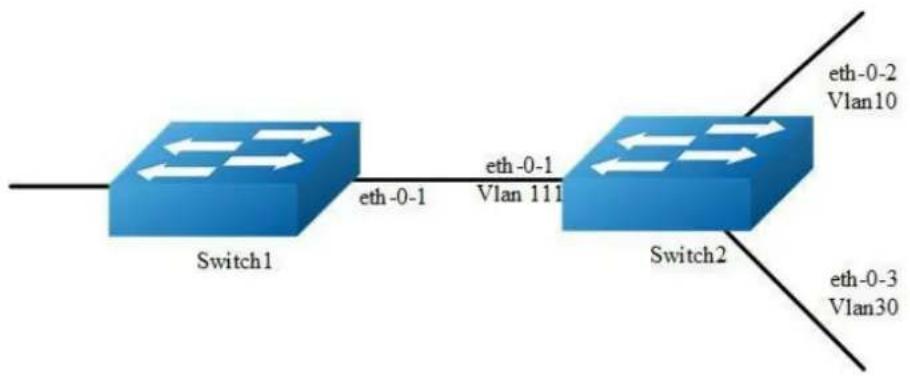
flowchart
graph LR
A["Switch1"] -->|eth-0-1| B["Switch2"]
B -->|eth-0-2\nVlan10| C
B -->|eth-0-3\nVlan30| D
A -->|eth-0-1\nVlan 111| B
Figure 6-4 mvr
Enable IGMP&PIM-SM in the interface of eth-0-1 of Switch1.
Configure Switch2: eth-0-1 in vlan111, eth-0-2 in vlan10, and eth-0-3 vlan30.
Enable MVR in the Switch2, it is required that only one copy of multicast traffic from Switch1 is sent to Switch2, but HostA and HostC can both receive this multicast traffic.
step 1 Enter the configure mode
Switch# configure terminal
step 2 Enter the vlan configure mode and create vlan
Configure on switch1:
Switch(config)# vlan database
Switch(config-vlan)# vlan 111,10,30
Switch(config-vlan)# quit
step 3 Enter the interface configure mode, set the attributes and ip address, and enable pim-sm
Configure on switch1:
switch(config)# interface eth-0-1
switch(config-if)# no switchport
switch(config-if)# no shutdown
switch(config-if)# ip address 12.12.12.12/24
switch(config-if)# ip pim sparse-mode
switch(config-if)# exit
Configure on switch2:
Switch(config)# interface vlan 111
Switch(config-if)# exit
Switch(config)# interface vlan 10
Switch(config-if)# exit
Switch(config)# interface vlan 30
Switch(config-if)# exit
Switch(config)# interface eth-0-1
Switch(config-if)# switchport access vlan111
Switch(config)# interface eth-0-2
Switch(config-if)# switchport access vlan10
Switch(config)# interface eth-0-3
Switch(config-if)# switchport access vlan30
Switch(config-if)# exit
step 4 Enable MVR
Configure on switch2:
Switch(config)# no ip multicast-routing
Switch(config)# mvr
Switch(config)# mvr vlan 111
Switch(config)# mvr group 238.255.0.1 64
Switch(config)# mvr source-address 12.12.12.1
Switch(config)# interface eth-0-1
Switch(config-if)# mvr type source
Switch(config)# interface eth-0-2
Switch(config-if)# mvr type receiver vlan 10
Switch(config)# interface eth-0-3
Switch(config-if)# mvr type receiver vlan 30
Switch(config-if)# exit
step 5 Exit the configure mode
Switch(config)# end
step 6 Validation
Switch1
| Switch# show ip igmp groupsIGMP Connected Group Membership | ||||
| Group Address | Interface | Uptime | Expires | Last Reporter |
| 238.255.0.1 | eth-0-1 | 00:01:16 | 00:03:49 | 12.12.12.1 |
| 238.255.0.2 | eth-0-1 | 00:01:16 | 00:03:49 | 12.12.12.1 |
| 238.255.0.3 | eth-0-1 | 00:01:16 | 00:03:49 | 12.12.12.1 |
| 238.255.0.4 | eth-0-1 | 00:01:16 | 00:03:49 | 12.12.12.1 |
| 238.255.0.5 | eth-0-1 | 00:01:16 | 00:03:49 | 12.12.12.1 |
| 238.255.0.6 | eth-0-1 | 00:01:16 | 00:03:49 | 12.12.12.1 |
| 238.255.0.7 | eth-0-1 | 00:01:16 | 00:03:49 | 12.12.12.1 |
| 238.255.0.8 | eth-0-1 | 00:01:16 | 00:03:49 | 12.12.12.1 |
| 238.255.0.9 | eth-0-1 | 00:01:16 | 00:03:49 | 12.12.12.1 |
| 238.255.0.10 | eth-0-1 | 00:01:16 | 00:03:49 | 12.12.12.1 |
| ...... | ||||
| 238.255.0.64 | eth-0-1 | 00:01:16 | 00:03:49 | 12.12.12.1 |
Switch2
| Switch# show mvr | ||||
| MVR Running: TRUE | ||||
| MVR Multicast VLAN: 111 | ||||
| MVR Source-address: 12.12.12.1 | ||||
| MVR Max Multicast Groups: 1024 | ||||
| MVR Hw Rt Limit: 508 | ||||
| MVR Current Multicast Groups: 255 | ||||
| Switch# show mvr groups | ||||
| VLAN | Interface | Group-Address | Uptime | Expires-time |
| 10 | eth-0-2 | 238.255.0.1 | 00:03:23 | 00:02:03 |
| 10 | eth-0-2 | 238.255.0.2 | 00:02:16 | 00:02:03 |
| 10 | eth-0-2 | 238.255.0.3 | 00:02:16 | 00:02:03 |
| 10 | eth-0-2 | 238.255.0.4 | 00:02:16 | 00:02:03 |
| 10 | eth-0-2 | 238.255.0.5 | 00:02:16 | 00:02:03 |
| 10 | eth-0-2 | 238.255.0.6 | 00:02:16 | 00:02:04 |
| 10 | eth-0-2 | 238.255.0.7 | 00:02:16 | 00:02:04 |
| 10 | eth-0-2 | 238.255.0.8 | 00:02:16 | 00:02:04 |
| 10 | eth-0-2 | 238.255.0.9 | 00:02:16 | 00:02:04 |
| 10 | eth-0-2 | 238.255.0.10 | 00:02:16 | 00:02:04 |
| ...... | ||||
| 10 | eth-0-2 | 238.255.0.64 | 00:01:50 | 00:02:29 |
6.6.3 Application cases
N/A
7 Security Configuration Guide
7.1 Configuring Port Security
7.1.1 Overview
Function Introduction
Port security feature is used to limit the number of “secure” dynamic MAC addresses learnt on a particular interface. The interface will forward packets only with source MAC addresses that match these secure addresses. The secure MAC addresses can be created manually, or learnt automatically. After the number of secure dynamic MAC addresses reaches the limit for the number of secure dynamic MAC addresses, new MAC address can’t be learnt (it can still be statically configured) on the interface. if the interface then receives a packet with a source MAC address that is different with any of the secure addresses, it is considered as a security violation and should be discarded.
Port security feature also binds a MAC to a port so that the port does not forward packets with source addresses that are outside of defined addresses. If a MAC addresses configured or learnt on a secure port attempts to access another port, this is also considered as a security violation.
Two types of secure MAC addresses are supported:
Static secure MAC addresses: These are manually configured by the interface configuration command "switchport port-security mac-address".
Dynamic secure MAC addresses: These are dynamically learnt.
If a security violation occurs, the packets to be forwarded will be dropped. User can configure the action by command “switchport port-security violation”. There are three actions can be chosen:
errdisable: discard the packet and set the port to errdisable status. Please reference to Ethernet configuration guide, chapter errdisable.
protect: discard only.
restrict: discard and record the event in log.
Principle Description
N/A
7.1.2 Configuration
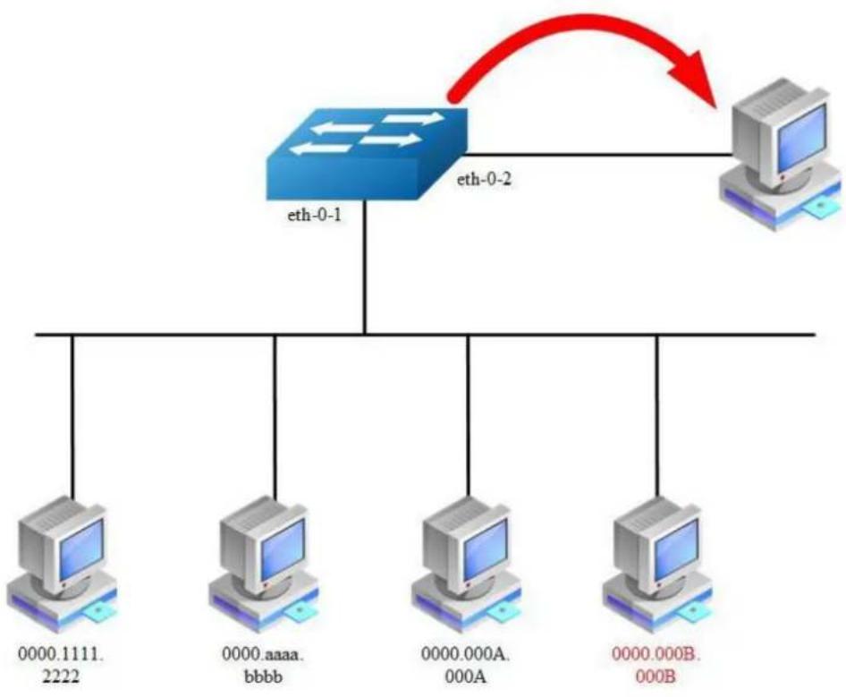
flowchart
graph TD
A["eth-0-1"] --> B["0000.1111.2222"]
A --> C["0000.aaaa.bbbb"]
A --> D["0000.000A.000A"]
A --> E["0000.000B.000B"]
F["eth-0-2"] --> A
style A fill:#333,stroke:#fff,color:#fff
style B fill:#fff,stroke:#333
style C fill:#fff,stroke:#333
style D fill:#fff,stroke:#333
style E fill:#fff,stroke:#333
Figure 7-1 Port Security
According to the topology above, only receive three Mac entries and discard source mac 0000.000B.000B after the following configuration:
step 1 Enter the configure mode
Switch# configure terminal
step 2 Enter the interface configure mode, set the attributes, and enable pim-sm
Switch(config)# interface eth-0-1
Switch(config-if)# switchport
Switch(config-if)# switchport port-security
Switch(config-if)# switchport port-security maximum 2
Switch(config-if)# switchport port-security mac-address 0000.1111.2222 vlan 1
Switch(config-if)# switchport port-security violation restrict
Switch(config-if)# exit
step 3 Exit the configure mode
Switch(config)# end
step 4 Validation
Switch# show port-security
Secure Port MaxSecureAddr CurrentAddr SecurityViolationMode
(Count) (DynamicCount)
eth-0-1 2 2 restrict
Switch# show port-security address-table
Secure MAC address table
Vlan Mac Address Type Ports
1 0000.1111.2222 SecureConfigured eth-0-1
1 0000.aaaa.bbbb SecureLearned eth-0-1
1 0000.000a.000a SecureLearned eth-0-1
Switch# show port-security interface eth-0-1
Port security : enabled
Violation mode : discard packet and log
Maximum dynamic MAC addresses : 2
Total MAC addresses : 3
Static configured MAC addresses : 1
7.1.3 Application cases
N/A
7.2 Configuring Vlan Security
7.2.1 Overview
Function Introduction
Vlan security feature is used to limit the total number of MAC addresses learnt in a particular vlan. The MAC addresses can be added manually, or learnt automatically. After the device reaches the limit for the number of MAC addresses on the vlan, if the vlan receives a packet with an unknown source MAC address, the configured action will take effect.
Two types of MAC addresses are supported:
Static MAC addresses: These are manually configured by users.
Dynamic MAC addresses: These are dynamically learnt.
User can set the action for unknown source MAC packets after the MAC address table count exceed max by using command line “vlan X mac-limit action”. Three types of actions are supported:
Discard: Packet with an unknown source MAC address from the vlan will be discarded and its source MAC address will not be learnt.
Warn: Packet with an unknown source MAC address from the vlan will be discarded, its source MAC address will not be learnt, but warning log will be printed in syslog.
Forward: Packets from the vlan will be forwarded without MAC learning or warning log.
MAC address learning feature can be enabled or disabled per-VLAN.
Principle Description
N/A
7.2.2 Configuration
Configuring vlan mac-limit
step 1 Enter the configure mode
Switch# configure terminal
step 2 Enter the vlan configure mode and create vlan, set the the maximum of MAC addresses and the action at exceeding
Switch# configure terminal
Switch(config)# vlan database
Switch(config)# vlan 2
Switch(config-vlan)# vlan 2 mac-limit maximum 100
Switch(config-vlan)# vlan 2 mac-limit action discard
Switch(config-vlan)# exit
step 3 Exit the configure mode
Switch(config)# end
step 4 Validation
Switch# show vlan-security
Vlan learning-en max-mac-count cur-mac-count action
2 Enable 100 0 Discard
Configuring vlan mac learning
step 1 Enter the configure mode
Switch# configure terminal
step 2 Enter the vlan configure mode and create vlan, set the mac learning states
Switch(config)# vlan database
Switch(config)# vlan 2
Switch(config-vlan)# vlan 2 mac learning disable
Switch(config-vlan)# exit
step 3 Exit the configure mode
Switch(config)# end
step 4 Validation
Switch# show vlan-security
Vlan learning-en max-mac-count cur-mac-count action
2 Disable 100 0 Discard
7.2.3 Application cases
N/A
7.3 Configuring Time-Range
7.3.1 Overview
Function Introduction
A time range is created that defines specific absolute times or periodic times of the day and week in order to implement time-based function, such as ACLs. The time range is identified by a name and then referenced by a function, which by itself has no relevance. Therefore, the time restriction is imposed on the function itself. The time range relies on the system clock.
Principle Description
N/A
7.3.2 Configuration
Create an absolute time range
step 1 Enter the configure mode
Switch# configure terminal
step 2 Create a time-range and set absolute time
Switch(config)# time-range test-absolute
Switch(config-tm-range)# absolute start 1:1:2 jan 1 2012 end 1:1:3 jan 7 2012
Switch(config-tm-range)# exit
step 3 Exit the configure mode
Switch(config)# end
step 4 Validation
DUT1# show time-range
time-range test-absolute
absolute start 01:01:02 Jan 01 2012 end 01:01:03 Jan 07 2012
Create a periodic time range
step 1 Enter the configure mode
Switch# configure terminal
step 2 Create a time-range and set periodic time
Switch(config)# time-range test-periodic
Switch(config-tm-range)# periodic 1:1 mon to 1:1 wed
Switch(config-tm-range)# exit
step 3 Exit the configure mode
Switch(config)# end
step 4 Validation
DUT1# show time-range
time-range test-periodic
periodic 01:01 Mon to 01:01 Wed
7.3.3 Application cases
N/A
7.4 Configuring ACL
7.4.1 Overview
Function Introduction
Access control lists (ACLs) classify traffic with the same characteristics. The ACL can have multiple access control entries (ACEs), which are commands that match fields against the contents of the packet. ACLs can filter packets received on interface by many fields such as ip address, mac address and deny or permit the packets.
Principle Description
The following terms and concepts are used to describe ACL:
Access control entry (ACE): Each ACE includes an action element (permit or deny) and a series of filter element based on criteria such as source address, destination address, protocol, and protocol-specific parameters.
MAC ACL: MAC ACL can filter packet by mac-sa and mac-da, and the mac-address can be masked, or configured as host id, or configured as any to filter all MAC addresses. MAC ACL can also filter other L2 fields such as COS, VLAN-ID, INNER-COS, INNER-VLAN-ID, L2 type, L3 type.
IPv4 ACL: IPv4 ACL can filter packet by ip-sa and ip-da, and ip-address can be masked, or configured as host id, or configured as any to filter all IPv4 address. IPv4 ACL can also filter other L3 fields such as DSCP, L4 protocol and L4 fields such as TCP port, UDP port, and so on.
Time Range: Time range can define a period of time only between which the ACE can be valid if the ACE is associated to the time range.
7.4.2 Configuration
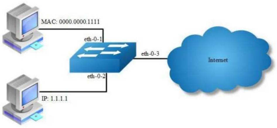
flowchart
graph LR
A["Computer 1"] -->|MAC: 0000.0000.1111| B["Router"]
C["Computer 2"] -->|IP: 1.1.1.1| B
B -->|eth-0-3| D["Internet"]
B -->|eth-0-2| B
Figure 7-2 acl
In this example, use MAC ACL on interface eth-0-1, to permit packets with source mac 0000.0000.1111 and deny any other packets. Use IPv4 ACL on interface eth-0-2, to permit packets with source ip 1.1.1.1/24 and deny any other packets.
step 1 Enter the configure mode
Switch# configure terminal
step 2 Create access list
mac access list:
Switch(config)# mac access-list mac
Switch(config-mac-acl)# permit src-mac host 0000.0000.1111 dest-mac any
Switch(config-mac-acl)# deny src-mac any dest-mac any
Switch(config-mac-acl)# exit
ip access list:
Switch(config)# ip access-list ipv4
Switch(config-ip-acl)# permit any 1.1.1.1 0.0.0.255 any
Switch(config-ip-acl)# deny any any any
Switch(config-ip-acl)# exit
step 3 Create class-map, and bind the access list
Switch(config)# class-map cmap1
Switch(config-cmap)# match access-group mac
Switch(config-cmap)# exit
Switch(config)# class-map cmap2
Switch(config-cmap)# match access-group ipv4
Switch(config-cmap)# exit
step 4 Create policy-map and bind the class map
Switch(config)# policy-map pmap1
Switch(config-pmap)# class cmap1
Switch(config-pmap-c)# exit
Switch(config-pmap)# exit
Switch(config)# policy-map pmap2
Switch(config-pmap)# class cmap2
Switch(config-pmap-c)# exit
Switch(config-pmap)# exit
step 5 Apply the policy to the interface
Switch(config)# interface eth-0-1
Switch(config-if)# service-policy input pmap1
Switch(config-if)# exit
Switch(config-if)# interface eth-0-2
Switch(config-if)# service-policy input pmap2
Switch(config-if)# exit
step 6 Exit the configure mode
Switch(config)# end
step 7 Validation
The result of show running-config is as follows:
Switch# show running-config
mac access-list mac
10 permit src-mac host 0000.0000.1111 dest-mac any
20 deny src-mac any dest-mac any
!
ip access-list ipv4
10 permit any 1.1.1.0 0.0.0.255 any
20 deny any any any
!
class-map match-any cmap1
match access-group mac
!
class-map match-any cmap2
match access-group ipv4
!
policy-map pmap1
class cmap1
!
policy-map pmap2
class cmap2
!
interface eth-0-1
service-policy input pmap1
!
interface eth-0-2
service-policy input pmap2
!
7.4.3 Application cases
N/A
7.5 Configuring Extern ACL
7.5.1 Overview
Function Introduction
Extend IPv4 ACL combines MAC filters with IP filters in one access list. Different from MAC and IP ACL, extend ACL can access-control all packets (IP packets and non-IP packets). Extend ACL supported extend IPv4 ACL.
Principle Description
Following is a brief description of terms and concepts used to describe the extend ACL
:
Extend IPv4 ACL: Extend IPv4 ACL takes advantages of MAC ACL and IPv4 ACL, which combines MAC ACE with IPv4 ACE in an ACL to provide more powerful function of access-controlling traverse packets.
MAC ACE: Filter packets by mac-sa and mac-da, and the mac-address can be masked, or configured as host id, or configured as any to filter all MAC addresses. Other L2 fields, such as COS, VLAN-ID, INNER-COS, INNER-VLAN-ID, L2 type, L3 type, can also be filtered by MAC ACE.
IPv4 ACE: Filter packets by ip-sa and ip-da, and ip-address can be masked, or configured as host id, or configured as any to filter all IPv4 address. Other L3 fields such as DSCP, L4 protocol and L4 fields, such as TCP port, UDP port, can also be filtered by IPv4 ACE.
The MAC ACE and IPv4 ACE in an extend IPv4 ACL can be configured alternately in arbitrary order which is completely specified by user.
7.5.2 Configuration
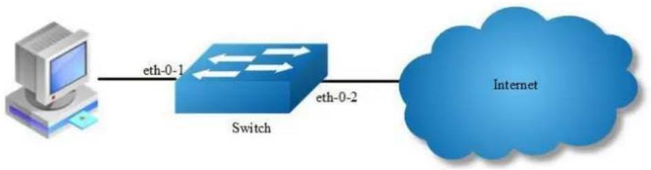
flowchart
graph LR
A["Computer"] -->|eth-0-1| B["Switch"]
B -->|eth-0-2| C["Internet"]
Figure 7-3 extern acl
In this example, use extend IPv4 ACL on interface eth-0-1, to permit packets with source mac 0000.0000.1111 and cos value of 2, permit all TCP packets, and deny any other packets.
step 1 Enter the configure mode
Switch# configure terminal
step 2 Create access list
Switch(config)# ip access-list ipxacl extend
Switch(config-ex-ip-acl)# permit src-mac host 0000.0000.1111 dest-mac any cos 2
Switch(config-ex-ip-acl)# permit tcp any any
Switch(config-ex-ip-acl)# deny src-mac any dest-mac any
Switch(config-ex-ip-acl)# end
step 3 Create class-map, and bind the access list
Switch(config)# class-map cmap
Switch(config-cmap)# match access-group ipxacl
Switch(config-cmap)# exit
step 4 Create policy-map and bind the class map
Switch(config)# policy-map pmap
Switch(config-pmap)# class cmap
Switch(config-pmap-c)# exit
Switch(config-pmap)# exit
step 5 Apply the policy to the interface
Switch(config)# interface eth-0-1
Switch(config-if)# service-policy input pmap
Switch(config-if)# exit
step 6 Exit the configure mode
Switch(config)# end
step 7 Validation
The result of show running-config is as follows:
Switch# show running-config
ip access-list ipxacl extend
10 permit src-mac host 0000.0000.1111 dest-mac any cos 2
20 permit tcp any any
30 deny src-mac any dest-mac any
!
class-map match-any cmap
match access-group ipxacl
!
policy-map pmap
class cmap
!
interface eth-0-1
service-policy input pmap
!
Switch# show access-list ip
ip access-list ipxacl extend
10 permit src-mac host 0000.0000.1111 dest-mac any cos 2
20 permit tcp any any
30 deny src-mac any dest-mac any
7.5.3 Application cases
N/A
7.6 Configuring IPv6 ACL
7.6.1 Overview
Function Introduction
Access control lists for IPv6 (ACLv6) classify traffic with the same characteristics. The ACLv6 can have multiple access control entries (ACEs), which are commands that match fields against the contents of the packet. ACLv6 can filter packets received on interface by many fields such as ipv6 address and deny or permit the packets.
Principle Description
The following terms and concepts are used to describe ACLv6.
Access control entry (ACE): Each ACE includes an action element (permit or deny) and a filter element based on criteria such as source address, destination address, protocol, and protocol-specific parameters.
IPv6 ACL: IPv6 ACL can filter packet by ipv6-sa and ipv6-da, and ipv6-address can be masked, or configured as host id, or configured as any to filter all IPv6 address. IPv6 ACL can also filter other L3 fields such as L4 protocol and L4 fields such as TCP port, UDP port, and so on.
Time Range: Time range can define a period of time only between which the ACE can be valid if the ACE is associated to the time range.
7.6.2 Configuration
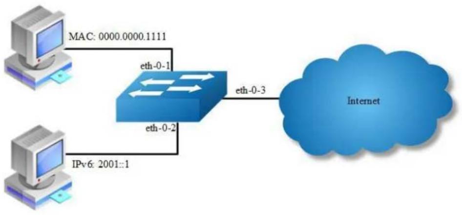
flowchart
graph LR
A["Computer 1"] -->|MAC: 0000.0000.1111| B["Router"]
C["Computer 2"] -->|IPv6: 2001::1| B
B -->|eth-0-3| D["Internet"]
B -->|eth-0-1| E["Mac"]
B -->|eth-0-2| F["Mac"]
Figure 7-4 ipv6 acl
step 1 Enter the configure mode
Switch# configure terminal
step 2 Enable IPv6 globally
Switch(config)# ipv6 enable
step 3 Create access list
mac access list:
Switch(config)# mac access-list mac
Switch(config-mac-acl)# permit src-mac host 0000.0000.1111 dest-mac any
Switch(config-mac-acl)# deny src-mac any dest-mac any
Switch(config-mac-acl)# exit
ipv6 access list:
Switch(config)# ipv6 access-list ipv6
Switch(config-ipv6-acl)# permit any 2001::/64 any
Switch(config-ipv6-acl)# deny any any any
Switch(config-ipv6-acl)# exit
step 4 Create class-map, and bind the access list
Switch(config)# class-map cmap1
Switch(config-cmap)# match access-group mac
Switch(config-cmap)# exit
Switch(config)# class-map cmap2
Switch(config-cmap)# match access-group ipv6
Switch(config-cmap)# exit
step 5 Create policy-map and bind the class map
Switch(config)# policy-map pmap1
Switch(config-pmap)# class cmap1
Switch(config-pmap-c)# exit
Switch(config-pmap)# exit
Switch(config)# policy-map pmap2
Switch(config-pmap)# class cmap2
Switch(config-pmap-c)# exit
Switch(config-pmap)# exit
step 6 Apply the policy to the interface
Switch(config)# interface eth-0-1
Switch(config-if)# service-policy input pmap1
Switch(config-if)# exit
Switch(config-if)# interface eth-0-2
Switch(config-if)# service-policy input pmap2
Switch(config-if)# exit
step 7 Exit the configure mode
Switch(config)# end
step 8 Validation
If IPv6 is enabled globally, the IPv6 packet will not obey the MAC ACL rules:
Switch# show running-config
mac access-list mac
10 permit src-mac host 0000.0000.1111 dest-mac any
20 deny src-mac any dest-mac any
!
ipv6 access-list ipv6
10 permit any 2001::/64 any
20 deny any any any
!
class-map match-any cmap1
match access-group mac
!
class-map match-any cmap2
match access-group ipv4
!
policy-map pmap1
class cmap1
!
policy-map pmap2
class cmap2
!
interface eth-0-1
service-policy input pmap1
!
interface eth-0-2
service-policy input pmap2
!
7.6.3 Application cases
N/A
7.7 Configuring Port-Group
7.7.1 Overview
Function Introduction
Port-group is designed to implement a port group based on ACL rules. Multiple interfaces can be added to the port group, supporting physical interfaces and aggregation interfaces. When the user applies ACL policy to the port group, there's only one rule and the action of ACL has a aggregate effect.
Principle Description
N/A
7.7.2 Configuration
Create a port group
step 1 Enter the configure mode
Switch# configure terminal
step 2 Create a port group and add member interfaces
Switch(config)# port-group port_group_1
Switch(config-port-group)# member interface eth-0-1
Switch(config-port-group)# member interface agg 1
Switch(config-port-group)# exit
step 3 Exit the configure mode
Switch(config)# end
step 4 Validation
DUT1# show running-config port-group
port-group port_group_1
member interface eth-0-1
member interface agg1
7.7.3 Application cases
N/A
7.8 Configuring Vlan-Group
7.8.1 Overview
Function Introduction
Vlan-group is designed to implement a vlan group based on ACL rules. Multiple vlan can be added to the vlan group. When the user applies ACL policy to the vlan group, there's only one rule and the action of ACL has a aggregate effect.
Principle Description
N/A
7.8.2 Configuration
Create a vlan group
step 1 Enter the configure mode
Switch# configure terminal
step 2 Create a vlan group and add member vlan
Switch(config)# vlan-group vlan_group_1
Switch(config-vlan-group)# member vlan 10
Switch(config-vlan-group)# member vlan 20
Switch(config-vlan-group)# exit
step 3 Exit the configure mode
Switch(config)# end
step 4 Validation
DUT1# show running-config vlan-group
vlan-group vlan_group_1
member vlan 10
member vlan 20
7.8.3 Application cases
N/A
7.9 Configuring COPP ACL
7.9.1 Overview
Function Introduction
COPP is mainly used to diacard or limit the rate of the packets which is transmitted to cpu. It guarantees that cpu can deal with traffic normally. In the base of original exception, copp can make a careful control of the packets transmitted to cpu.
Principle Description
The following terms and concepts are used to describe ACL: - Access control entry (ACE): Each ACE includes an action element (permit or deny) and a series of filter element based on criteria such as source address, destination address, protocol, and protocol-specific parameters. - COPP ACL:COPP ACL deals with packets according to their exceptions, the system can support the following exceptions: any,ipda, fwd-to-cpu, slow-protocol, bpdu, erps, eapol, smart-link, dhcp, rip,ospf, pim, bgp, vrrp, ldp, ptp, rsvp, icmp-redirect, mcast-rpf-fail,macsa-
mismatch,vlan-security-discard, post-security-discard, ip-option,udld,dot1x-mac-bypass, 12protocol-tunnel, arp, igmp, ssh, telnet, mlag. COPP only deals with the packets transmitted to cpu, it will not handle the forwarding packets. - Time Range: Time range can define a period of time only between which the ACE can be valid if the ACE is associated to the time range.
7.9.2 Configuration
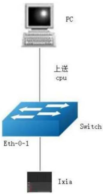
flowchart
graph TD
A["PC"] -->|上送 cpu| B["Eth-0-1"]
B --> C["Switch"]
C --> D["Ixia"]
Figure 7-5 copp_acl
In this example, use COPP ACL on interface eth-0-1, to discard the packets with arp exception transmitted to cpu. In the first place, you can use ixia to create a packet, Destination Address:001E.0811.065D, Source Address:0000.0010.0000, the type of arp is arp-request, Sender Hardware Address:0000.0000.0000, Target Protocol Address:10.0.0.1, the rest configuration information is as follows.
step 1 Enter the configure mode
Switch# configure terminal
step 2 Create copp access list
copp access list:
Switch(config)# control-plane access-list test1
Switch(config-cp-acl)# deny exception arp arp-request
Switch(config-cp-acl)# exit
step 3 Create class-map, and bind the copp access list
Switch(config)# class-map type control-plane cmap1
Switch(config-cmap-cp)# match access-group test1
Switch(config-cmap-cp)# exit
step 4 Create policy-map and bind the class map
Switch(config)#policy-map type control-plane pmap1
Switch(config-pmap-cp)#class type control-plane cmap1
Switch(config-pmap-cp-c)#exit
Switch(config-pmap-cp)#exit
step 5 Apply the policy to the interface
Switch(config)#control-plane
Switch(config-control-plane)#service-policy type control-plane input pmap1
step 6 Exit the configure mode
Switch(config)# end
step 7 Validation
The result of show running-config is as follows:
Switch# show running-config
control-plane access-list test1
10 deny exception arp arp-request
!
class-map type control-plane cmap1
match access-group test1
!
policy-map type control-plane pmap1
class type control-plane cmap1
!
control-plane
service-policy type control-plane input pmap1
The result of show cpu traffic-statistics receive is as follows:
Switch# show cpu traffic-statistics receive statistics rate time is 5 second(s) reason count (packets) rate (pps) arp 1029059 0
total 1029059 0
7.9.3 Application cases
N/A
7.10 Configuring dot1x
7.10.1 Overview
Function Introduction
IEEE 802 Local Area Networks are often deployed in environments that permit unauthorized devices to be physically attached to the LAN infrastructure, or Permit unauthorized users to attempt to access the LAN through equipment already attached.
Port-based network access control makes use of the physical access characteristics of IEEE 802 LAN infrastructures in order to provide a means of authenticating and authorizing devices attached to a LAN port that has point-to-point connection characteristics, and of preventing access to that port in cases in which the authentication and authorization process fails.
With 802.1X port-based authentication, the devices in the network have specific roles:
Client: the device (PC) that requests access to the LAN and switch services and responds to requests from the switch. The client software with support the follow the 802.1X standard should run on the PC. For linux system, we recommend the application which named “xsupplicant”.
Authentication server: performs the actual authentication of the client. The authentication server validates the identity of the client and notifies the switch whether or not the client is authorized to access the LAN and switch services. Because the switch acts as the proxy, the authentication service is transparent to the client. In this release, the Remote Authentication Dial-In User Service (RADIUS) security system with Extensible Authentication Protocol (EAP) extensions is the only supported authentication server. RADIUS operates
in a client/server model in which secure authentication information is exchanged between the RADIUS server and one or more RADIUS clients.
Switch (edge switch or wireless access point): controls the physical access to the network based on the authentication status of the client. The switch acts as an intermediary (proxy) between the client and the authentication server, requesting identity information from the client, verifying that information with the authentication server, and relaying a response to the client. The switch includes the RADIUS client, which is responsible for encapsulating and decapsulation the EAP frames and Interacting with the authentication server. When the switch receives EAPOL frames and relays them to the authentication server, the Ethernet header is stripped and the remaining EAP frame is re-encapsulated in the RADIUS format. The EAP Frames are not modified or examined during encapsulation, and the authentication server must support EAP within the native frame format. When the switch receives frames from the authentication server, the server's frame header is removed, leaving the EAP frame, which is then encapsulated for Ethernet and sent to the client. We can enable dot1x on routed port and access port.
Principle Description
Reference to IEEE Std 802.1X-2004
7.10.2 Configuration
Basic dot1x configuration
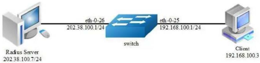
flowchart
graph LR
A["Radius Server\n202.38.100.7/24"] -->|eth-0-26\n202.38.100.1/24| B["switch"]
B -->|eth-0-25\n192.168.100.1/24| C["Client\n192.168.100.3"]
Figure 7-6 dot1x
step 1 Enter the configure mode
Switch# configure terminal
step 2 Enable dot1x globally
Switch(config)# dot1x system-auth-ctrl
step 3 Enter the interface configure mode, set the attributes of the interface and enable dot1x
Switch(config)# interface eth-0-25
Switch(config-if)# switchport mode access
Switch(config-if)# dot1x port-control auto
Switch(config-if)# no shutdown
Switch(config-if)# exit
Switch(config)# interface vlan 1
Switch(config-if)# ip address 192.168.100.1/24
Switch(config-if)# exit
step 4 Set the attributes of Layer 3 interface and set the Radius server
Switch(config)# interface eth-0-26
Switch(config-if)# no switchport
Switch(config-if)# ip address 202.38.100.1/24
Switch(config-if)# no shutdown
Switch(config-if)# exit
Switch(config)# radius-server host 202.38.100.7
Switch(config)# radius-server host 2001:1000::1
Switch(config)# radius-server key test
Switch(config)# exit
step 5 Exit the configure mode
Switch(config)# end
step 6 Validation
Switch# show dot1x
802.1X Port-Based Authentication Enabled
RADIUS server address: 2001:1000::1:1812
Next radius message ID: 0
RADIUS server address: 202.38.100.7:1812
Next radius message ID: 0
Switch# show dot1x interface eth-0-25
802.1X info for interface eth-0-25
portEnabled : true
portControl : Auto
portMode : Port based
portStatus : Authorized
Mac Auth bypass : disabled
reAuthenticate : disabled
reAuthPeriod : 3600
Max user number : 255
Current session number : 1
Accept user number : 1
Reject user number : 0
Guest VLAN : N/A
Assign VLAN : N/A
QuietPeriod : 60
ReqMax : 2
TxPeriod : 30
SuppTimeout : 30
ServerTimeout : 30
CD: adminControlledDirections : in
CD: operControlledDirections : in
CD: bridgeDetected : false
session 1: 1 - 0011.0100.0001
user name : admin
abort:F fail:F start:F timeout:F success:T
PAE: state: Authenticated - portMode: Auto
PAE: reAuthCount: 0 - rxRespId: 0
BE: state: Idle - reqCount: 0 - idFromServer: 5
Enable dot1x on routed port
The example above describes how to enable dot1x on access port. This function can also enable on routed port. The following example shows how to change eth-0-25 to a routed port and enable dot1x.
Switch(config)# interface eth-0-25
Switch(config-if)# no switchport
Switch(config-if)# ip address 192.168.100.1/24
Switch(config-if)# dotlx port-control auto
Switch(config-if)# no shutdown
Switch(config-if)# exit
Using force mode
Dot1x port control mode can be force-authorized or force-unauthorized.
force-authorized:
Switch(config)# interface eth-0-25
Switch(config-if)# dotlx port-control force-authorized
Switch(config-if)# exit
force-unauthorized:
Switch(config)# interface eth-0-25
Switch(config-if)# dotlx port-control force-unauthorized
Switch(config-if)# exit
User can choose port control mode as force-authorized, force-unauthorized or auto.
The final configuration should over write the previous one.
Enable dot1x accounting
Dot1x accounting can be used to keep track of network usage after user is authenticated. Dot1x accounting is disabled by default, you can enable it on globally configure mode.
Enable dot1x accounting:
Switch(config)# dotlx accounting-mode radius
Device sends accounting start request to server after user is authenticated when dot1x accounting is enabled, if no corresponding response is received, start-fail policy is needed :
online: In order to avoid the impact of network failure on users, online policy can be configured to allow users to be online.
offline: If dot1x accounting start fail, offline policy can be configured to reject users to be online.
Switch(config)# dot1x accounting start-fail online
User can configure realtime accounting to make device send realtime accounting request to server periodically. Server keeps accounting users only when received realtime accounting request, so that abnormal accounting can be avoided when server can not receive accounting stop packet from device.
Meanwhile, user can configure max times of realtime accounting with no response and the action when realtime accounting fails. By default, the max times of realtime accounting with no response is set to 3, and user is allowed to be online after realtime accounting failure.
Switch(config)# dot1x accounting realtime 60 Switch(config)# dot1x accounting interim-fail max-times 2 offline
dot1x optional parameter
Timer for Radius server: Set the wait time for re-activating RADIUS server; Set the maximum failed RADIUS requests sent to server; Set the timeout value for no response from RADIUS server.
Switch(config)# radius-server deadtime 10
Switch(config)# radius-server retransmit 5
Switch(config)# radius-server timeout 10
Interface attributes: Specify the number of reauthentication attempts before becoming unauthorized; Set the protocol version; Specify the quiet period in the HELD state; Enable reauthentication on a port; Specify the seconds between reauthorization attempts; Specify the authentication server response timeout; Specify the supplicant response timeout; Specify the Seconds between successive request ID attempts;
Enable dot1x handshake with client on a port; Specify the handshake period.
Switch(config)# interface eth-0-25
Switch(config-if)# dotlx max-req 5
Switch(config-if)# dotlx protocol-version 1
Switch(config-if)# dotlx quiet-period 120
Switch(config-if)# dotlx reauthentication
Switch(config-if)# dotlx timeout re-authperiod 1800
Switch(config-if)# dotlx timeout server-timeout 60
Switch(config-if)# dotlx timeout supp-timeout 60
Switch(config-if)# dotlx timeout tx-period 60
Switch(config-if)# dotlx handshake
Switch(config-if)# dotlx timeout handshake-period 1
Switch(config-if)# exit
7.10.3 Application cases
Radius server configuration (Using WinRadius for example)
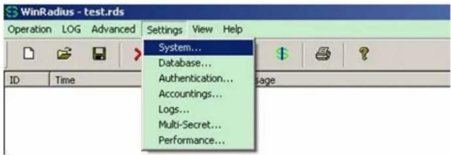
Figure 7-7 Select "Setting-> System"
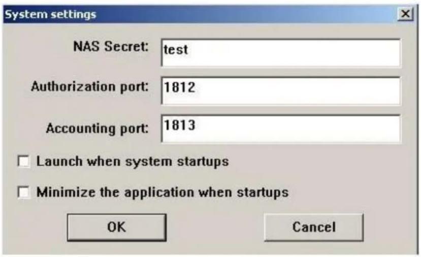
Figure 7-8 Configure the shared-key, authorization port and account port
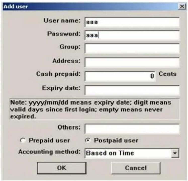
Figure 7-9 Add user name and password on the server
7.11 Configuring Guest VLAN
7.11.1 Overview
Function Introduction
You can configure a guest VLAN for each 802.1x port on the switch to provide limited services to clients (for example, how to download the 802.1x client). These clients might be upgrading their system for 802.1x authentication, and some hosts, such as Windows 98 systems, might not be 802.1x-capable.
When the authentication server does not receive a response to its EAPOL request/identity frame, clients that are not 802.1x-capable are put into the guest VLAN for the port, if one is configured. However, the server does not grant 802.1x-capable clients that fail authentication access to the network. Any number of hosts is allowed access when the switch port is moved to the guest VLAN.
The guest VLAN feature is not supported on internal VLANs (routed ports) or trunk ports; it is supported only on access ports.

NOTE
Guest VLAN is supported on access port, and not supported on routed port or trunk port.
Principle Description
无
7.11.2 Configuration
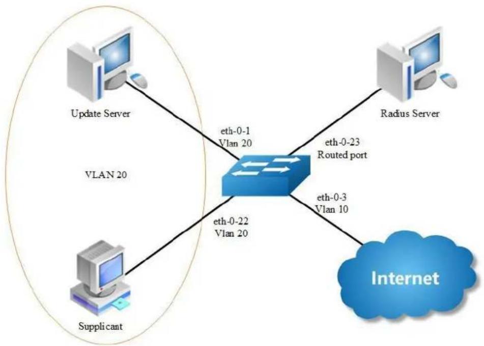
flowchart
graph TD
A["Update Server"] -->|eth-0-1\nVlan 20| B["Router"]
C["Supplicant"] -->|eth-0-22\nVlan 20| B
D["Radius Server"] -->|eth-0-23\nRouted port| B
B -->|eth-0-3\nVlan 10| E["Internet"]
Figure 7-10 Guest vlan: before authenticated
In the above topology, eth-0-22 is an IEEE 802.1X enabled port, and it is in the native VLAN 10, the configured guest VLAN for this port is VLAN 20. So clients that are not 802.1X capable will be put into VLAN 20 after the authenticator had send max EAPOL request/identity frame but got no response.
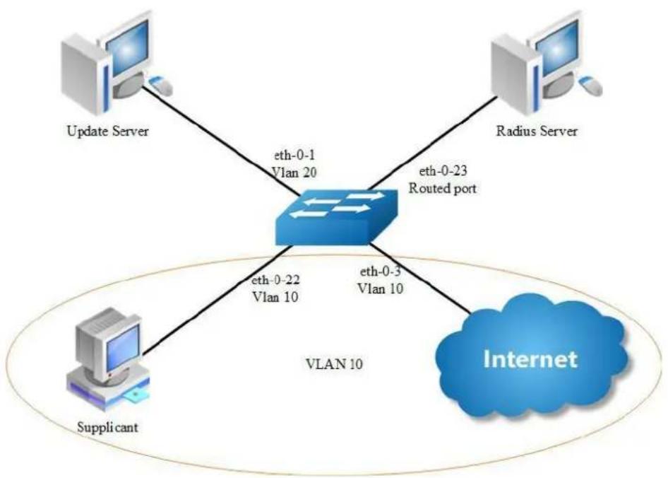
flowchart
graph TD
A["Update Server"] -->|eth-0-1\nVlan 20| B["VLAN 10"]
C["Radius Server"] -->|eth-0-23\nRouted port| B
D["Supplicant"] -->|eth-0-22\nVlan 10| B
B -->|eth-0-3\nVlan 10| E["Internet"]
Figure 7-11 Guest vlan: after authenticated
We use remote linux Radius server as authenticate server, the server's address is 202.38.100.7, and the IP address for the connected routed port eth-0-23 is 202.38.100.1. When the client is authenticated by the radius server, then it can access the public internet which is also in VLAN 10.
step 1 Enter the configure mode
Switch# configure terminal
step 2 Enter the vlan configure mode and create vlan
Switch(config)# vlan database
Switch(config-vlan)# vlan 10
Switch(config-vlan)# vlan 20
Switch(config-vlan)# exit
step 3 Enable dot1x globally
Switch(config)# dot1x system-auth-ctrl
step 4 Enter the interface configure mode, set the attributes of the interface and enable dot1x and set guest vlan
Switch(config)# interface eth-0-22
Switch(config-if)# switchport mode access
Switch(config-if)# switchport access vlan 10
Switch(config-if)# dot1x port-control auto
Switch(config-if)# no shutdown
Switch(config-if)# dot1x guest vlan 20
Switch(config-if)# exit
step 5 Set the attributes of Layer 3 interface and set the Radius server
Switch(config)# interface eth-0-23
Switch(config-if)# no switchport
Switch(config-if)# ip address 202.38.100.1/24
Switch(config-if)# no shutdown
Switch(config-if)# exit
Switch(config)# radius-server host 202.38.100.7
Switch(config)# radius-server key test
Switch(config)#end
step 6 Exit the configure mode
Switch(config)# end
step 7 Validation
Init state:
Switch# show running-config
dot1x system-auth-ctrl
radius-server host 202.38.100.7 key test
vlan database
vlan 10,20
!
interface eth-0-22
switchport access vlan 10
dot1x port-control auto
dot1x guest-vlan 20
!
interface eth-0-23
no switchport
ip address 202.38.100.1/24
!
Switch# show dot1x interface eth-0-22
802.1X info for interface eth-0-22
portEnabled : true
portControl : Auto
portMode : Port based
portStatus : Unauthorized
Mac Auth bypass : disabled
reAuthenticate : disabled
reAuthPeriod : 3600
Max user number : 255
Current session number : 0
Accept user number : 0
Reject user number : 0
Guest VLAN : 20
Assign VLAN : N/A
QuietPeriod : 60
ReqMax : 2
TxPeriod : 30
SuppTimeout : 30
ServerTimeout : 30
CD: adminControlledDirections : in
CD: operControlledDirections : in
CD: bridgeDetected : false
Switch# show vlan brief
VLAN ID Name State STP ID DSCP Member ports
(u)-Untagged, (t)-Tagged
1 default ACTIVE 0 Disable eth-0-1(u) eth-0-2(u)
eth-0-3(u) eth-0-4(u)
eth-0-5(u) eth-0-6(u)
eth-0-7(u) eth-0-8(u)
eth-0-9(u) eth-0-10(u)
eth-0-11(u) eth-0-12(u)
eth-0-13(u) eth-0-14(u)
eth-0-15(u) eth-0-16(u)
eth-0-17(u) eth-0-18(u)
eth-0-19(u) eth-0-20(u)
eth-0-21(u) eth-0-24(u)
eth-0-25(u) eth-0-26(u)
eth-0-27(u) eth-0-28(u)
eth-0-29(u) eth-0-30(u)
eth-0-31(u) eth-0-32(u)
eth-0-33(u) eth-0-34(u)
eth-0-35(u) eth-0-36(u)
eth-0-37(u) eth-0-38(u)
eth-0-39(u) eth-0-40(u)
eth-0-41(u) eth-0-42(u)
eth-0-43(u) eth-0-44(u)
eth-0-45(u) eth-0-46(u)
eth-0-47(u) eth-0-48(u)
10 VLAN0010 ACTIVE 0 Disable eth-0-22(u)
20 VLAN0020 ACTIVE 0 Disable
After configure the guest vlan:
unauthorized:
Switch# show dotlx interface eth-0-22
802.1X info for interface eth-0-22
portEnabled : true
portControl : Auto
portMode : Port based
portStatus : Unauthorized
Mac Auth bypass : disabled
reAuthenticate : disabled
reAuthPeriod : 3600
Max user number : 255
Current session number : 1
Accept user number : 0
Reject user number : 1
Guest VLAN : 20 (Port Authorized by guest vlan)
Assign VLAN : N/A
QuietPeriod : 60
ReqMax : 2
TxPeriod : 30
SuppTimeout : 30
ServerTimeout : 30
CD: adminControlledDirections : in
CD: operControlledDirections : in
CD: bridgeDetected : false
session 1: 1 - 0011.0100.0001
user name : admin
abort:F fail:T start:F timeout:F success:F
PAE: state: Held - portMode: Auto
PAE: reAuthCount: 1 - rxRespId: 0
BE: state: Idle - reqCount: 0 - idFromServer: 92
Switch# show vlan brief
VLAN ID Name State STP ID DSCP Member ports
(u)-Untagged, (t)-Tagged
1 default ACTIVE 0 Disable eth-0-1(u) eth-0-2(u)
eth-0-3(u) eth-0-4(u)
eth-0-5(u) eth-0-6(u)
eth-0-7(u) eth-0-8(u)
eth-0-9(u) eth-0-10(u)
eth-0-11(u) eth-0-12(u)
eth-0-13(u) eth-0-14(u)
eth-0-15(u) eth-0-16(u)
eth-0-17(u) eth-0-18(u)
eth-0-19(u) eth-0-20(u)
eth-0-21(u) eth-0-24(u)
eth-0-25(u) eth-0-26(u)
eth-0-27(u) eth-0-28(u)
eth-0-29(u) eth-0-30(u)
eth-0-31(u) eth-0-32(u)
eth-0-33(u) eth-0-34(u)
eth-0-35(u) eth-0-36(u)
eth-0-37(u) eth-0-38(u)
eth-0-39(u) eth-0-40(u)
eth-0-41(u) eth-0-42(u)
eth-0-43(u) eth-0-44(u)
eth-0-45(u) eth-0-46(u)
eth-0-47(u) eth-0-48(u)
10 VLAN0010 ACTIVE 0 Disable
20 VLAN0020 ACTIVE 0 Disable eth-0-22(u)
Client is authenticated
authorized:
Switch# show dot1x interface eth-0-22
802.1X info for interface eth-0-22
portEnabled : true
portControl : Auto
portMode : Port based
portStatus : Authorized
Mac Auth bypass : disabled
reAuthenticate : disabled
reAuthPeriod : 3600
Max user number : 255
Current session number : 1
Accept user number : 1
Reject user number : 0
Guest VLAN : 20
Assign VLAN : N/A
QuietPeriod : 60
ReqMax : 2
TxPeriod : 30
SuppTimeout : 30
ServerTimeout : 30
CD: adminControlledDirections : in
CD: operControlledDirections : in
CD: bridgeDetected : false
session 1: 1 - 0011.0100.0001
user name : admin
abort:F fail:F start:F timeout:F success:T
PAE: state: Authenticated - portMode: Auto
PAE: reAuthCount: 0 - rxRespId: 0
BE: state: Idle - reqCount: 0 - idFromServer: 207
Switch# show vlan brief
VLAN ID Name State STP ID DSCP Member ports
(u)-Untagged, (t)-Tagged
I default ACTIVE 0 Disable eth-0-1(u) eth-0-2(u)
eth-0-3(u) eth-0-4(u)
eth-0-5(u) eth-0-6(u)
eth-0-7(u) eth-0-8(u)
eth-0-9(u) eth-0-10(u)
eth-0-11(u) eth-0-12(u)
eth-0-13(u) eth-0-14(u)
eth-0-15(u) eth-0-16(u)
eth-0-17(u) eth-0-18(u)
eth-0-19(u) eth-0-20(u)
eth-0-21(u) eth-0-24(u)
eth-0-25(u) eth-0-26(u)
eth-0-27(u) eth-0-28(u)
eth-0-29(u) eth-0-30(u)
eth-0-31(u) eth-0-32(u)
eth-0-33(u) eth-0-34(u)
eth-0-35(u) eth-0-36(u)
eth-0-37(u) eth-0-38(u)
eth-0-39(u) eth-0-40(u)
eth-0-41(u) eth-0-42(u)
eth-0-43(u) eth-0-44(u)
eth-0-45(u) eth-0-46(u)
eth-0-47(u) eth-0-48(u)
10 VLAN0010 ACTIVE 0 Disable eth-0-22(u)
20 VLAN0020 ACTIVE 0 Disable
Switch# show dotlx
802.1X Port-Based Authentication Enabled
RADIUS server address: 202.38.100.7:1812
Next radius message ID: 0
Switch# show dotlx statistics
802.1X statistics for interface eth-0-22
EAPOL Frames Rx: 52 - EAPOL Frames Tx: 4270
EAPOL Start Frames Rx: 18 - EAPOL Logoff Frames Rx: 2
EAP Rsp/Id Frames Rx: 29 - EAP Response Frames Rx: 3
EAP Req/Id Frames Tx: 3196 - EAP Request Frames Tx: 3
Invalid EAPOL Frames Rx: 0 - EAP Length Error Frames Rx: 0
EAPOL Last Frame Version Rx: 2 - EAPOL Last Frame Src: ae38.3288.f046
7.11.3 Application cases
N/A
7.12 Configuring ARP Inspection
7.12.1 Overview
Function Introduction
ARP inspection is a security feature that validates ARP packets in a network. ARP inspection intercepts, logs, and discards ARP packets with invalid IP-to-MAC address bindings. This capability protects the network from some man-in-the-middle attacks. ARP inspection ensures that only valid ARP requests and responses are relayed. The switch performs these activities:
Intercept all ARP requests and responses on untrusted ports.
Verify that each of these intercepted packets has a valid IP-to-MAC address binding before updating the local ARP cache or before forwarding the packet to the appropriate destination.
Drop invalid ARP packets.
ARP inspection determines the validity of an ARP packet based on valid IP-to-MAC address bindings stored in a trusted database, the DHCP snooping binding database. This database is built by DHCP snooping if DHCP snooping is enabled on the VLANs and on the switch. If the ARP packet is received on a trusted interface, the switch forwards the packet without any checks. On entrusted interfaces, the switch forwards the packet only if it is valid.
Principle Description
Following is a brief description of terms and concepts used to describe the ARP Inspection:
DHCP Snooping: DHCP snooping is a security feature that acts like a firewall between untrusted hosts and trusted DHCP servers. This feature builds and maintains the DHCP snooping binding database, which contains information about untrusted hosts with leased IP addresses.
Address Resolution Protocol (ARP): ARP provides IP communication within a Layer 2 broadcast domain by mapping an IP address to a MAC address. For example, Host B wants to send information to Host A, but it does not have the MAC address of Host A in its ARP cache. Host B generates a broadcast message for all hosts within the broadcast domain to obtain the MAC address associated with the IP address of Host A. All hosts within the broadcast domain receive the ARP request, and Host A responds with its MAC address.
7.12.2 Configuration
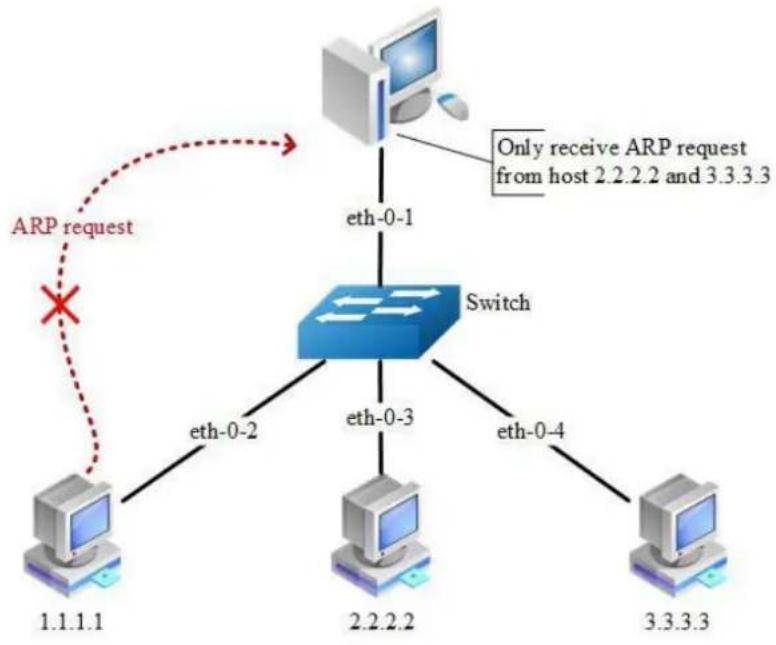
flowchart
graph TD
A["Computer"] -->|eth-0-1| B["Switch"]
B -->|eth-0-2| C["Computer 1.1.1.1"]
B -->|eth-0-3| D["Computer 2.2.2.2"]
B -->|eth-0-4| E["Computer 3.3.3.3"]
F["ARP request"] -.-> G["Switch"]
G -->|Only receive ARP request from host 2.2.2.2 and 3.3.3.3| A
Figure 7-12 arp inspection
step 1 Enter the configure mode
Switch# configure terminal
step 2 Enter the vlan configure mode and create vlan
Switch(config)# vlan database Switch(config-vlan)# vlan 2
Switch(config-vlan)# exit
Switch(config)# exit
step 3 Enter the interface configure mode, add the interface into the vlan
Switch(config)# interface eth-0-1
Switch(config-if)# switchport access vlan 2
Switch(config-if)# exit
Switch(config)# interface eth-0-2
Switch(config-if)# switchport access vlan 2
Switch(config-if)# exit
Switch(config)# interface eth-0-3
Switch(config-if)# switchport access vlan 2
Switch(config-if)# exit
Switch(config)# interface eth-0-4
Switch(config-if)# switchport access vlan 2
Switch(config-if)# exit
step 4 Configure arp inspection
Switch(config)# interface eth-0-1
Switch(config-if)# ip arp inspection trust
Switch(config-if)# exit
Switch(config)# ip arp inspection vlan 2
Switch(config)# ip arp inspection validate src-mac ip dst-mac
step 5 Configure arp access list
Switch(config)# arp access-list test
Switch(config-arp-acl)# deny request ip host 1.1.1.1 mac any
Switch(config-arp-acl)# exit
Switch(config)# ip arp inspection filter test vlan 2
step 6 Exit the configure mode
Switch(config)# exit
step 7 Validation
Check the configuration of ARP Inspection on switch:
Switch# show ip arp inspection
Source Mac Validation : Enabled
Destination Mac Validation : Enabled
IP Address Validation : Enabled
Vlan Configuration ACL Match Static ACL
2 enabled test
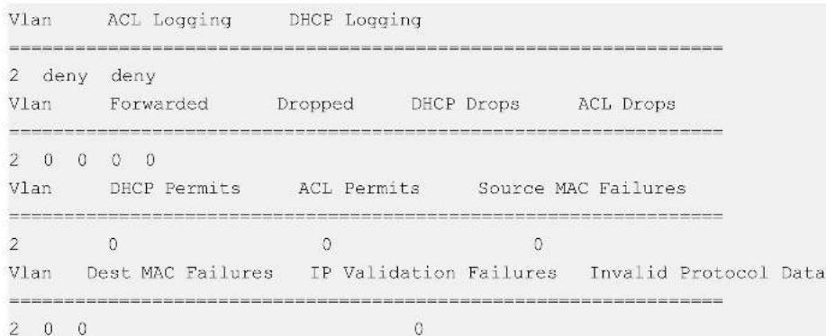
Show the log information of ARP Inspection on switch:
Switch# show ip arp inspection log
Total Log Buffer Size : 32
Syslog rate : 5 entries per 1 seconds.
1970-01-02 00:30:47 : Drop an ARP packet by ACL on vlan 2
1970-01-02 00:30:47 : Drop an ARP packet by ACL on vlan 2
1970-01-02 00:30:47 : Drop an ARP packet by ACL on vlan 2
1970-01-02 00:30:47 : Drop an ARP packet by ACL on vlan 2
1970-02-02 00:30:47 : Drop an ARP packet by ACL on vlan 2
1970-01-02 00:30:47 : Drop an ARP packet by ACL on vlan 2
1970-01-02 00:30:47 : Drop an ARP packet by ACL on vlan 2
1970-01-02 00.30:47 : Drop an ARP packet by ACL on vlan 2
1970-01-02 00:30:47 : Drop an ARP packet by ACL on vlan 2
1970-01-02 00:30:47 : Drop an ARP packet by ACL on vlan 2
1970-01-02 00:30:47 : Crop an ARP packet by ACL on vlan 2
1970-01-02 00:30:47 : Crop an ARP packet by ACL on vlan 2
1970-01-02 00:30:47 : Crop an ARP packet by ACL on vlan 2
1970-01-02 00:30:47 : Crop an ARP packet by ACL onvlan 2
1970-01-02 00:30:47 : Crop an ARP packet by ACL onvlan 2
1970-01-02 00:30:47 : Crop an ARP packet by ACL onvlan 2
7.12.3 Application cases
N/A
7.13 Configuring DHCP Snooping
7.13.1 Overview
Function Introduction
DHCP snooping is a security feature that acts like a firewall between untrusted hosts and trusted DHCP servers.
The DHCP snooping feature performs the following activities:
Validate DHCP messages received from untrusted sources and filters out invalid messages.
Build and maintain the DHCP snooping binding database, which contains information about untrusted hosts with leased IP addresses.
Utilize the DHCP snooping binding database to validate subsequent requests from untrusted hosts.
Other security features, such as dynamic ARP inspection (DAI), also use information stored in the DHCP snooping binding database. DHCP snooping is enabled on a per-VLAN basis. By default, the feature is inactive on all VLANs. You can enable the feature on a single VLAN or a range of VLANs. The DHCP snooping feature is implemented in software basis. All DHCP messages are intercepted in the BAY and directed to the CPU for processing.
Principle Description
N/A
7.13.2 Configuration
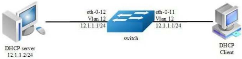
flowchart
graph LR
A["DHCP server 12.1.1.2/24"] -->|eth-0-12 Vlan 12 12.1.1.1/24| B["switch"]
B -->|eth-0-11 Vlan 12 12.1.1.1/24| C["DHCP Client"]
Figure 7-13 dhcp snooping
This figure is the networking topology for testing DHCP snooping functions. We need two Linux boxes and one switch to construct the test bed.
Computer A is used as a DHCP server.
Computer B is used as a DHCP client.
Switch is used as a DHCP Snooping box.
step 1 Enter the configure mode
Switch# configure terminal
step 2 Enter the vlan configure mode and create vlan
Switch(config)# vlan database
Switch(config-vlan)# vlan 12
Switch(config-vlan)# exit
step 3 Enter the interface configure mode, add the interface into the vlan
Switch(config)# interface eth-0-12
Switch(config-if)# switchport
Switch(config-if)# switchport access vlan 12
Switch(config-if)# dhcp snooping trust
Switch(config-if)# no shutdown
Switch(config-if)# exit
Switch(config)# interface eth-0-11
Switch(config-if)# switchport
Switch(config-if)# switchport access vlan 12
Switch(config-if)# no shutdown
Switch(config-if)# exit
Switch(config)# interface vlan 12
Switch(config-if)# ip address 12.1.1.1/24
Switch(config-if)# exit
step 4 Set DHCP attributes
Switch(config)# dhcp snooping verify mac-address
Switch(config)# service dhcp enable
Switch(config)# dhcp snooping
Switch(config)# dhcp snooping vlan 12
step 5 Exit the configure mode
Switch(config)# exit
step 6 Validation
Check the interface configuration.
Switch(config)# show running-config interface eth-0-12
!
interface eth-0-12
dhcp snooping trust
switchport access vlan 12
!
Switch(config)# show running-config interface eth-0-11
!
interface eth-0-11
switchport access vlan 12
Check the dhcp service status.
Switch# show services
Networking services configuration:
Service Name Status
dhcp enable
Print dhcp snooping configuration to check current configuration.
Switch# show dhcp snooping config
dhcp snooping service: enabled
dhcp snooping switch: enabled
Verification of hwaddr field: enabled
Insertion of relay agent information (option 82): disable
Relay agent information (option 82) on untrusted port: not allowed
dhcp snooping vlan 12
Show dhcp snooping statistics.
Switch# show dhcp snooping statistics
DHCP snooping statistics:
DHCP packets 17
BOOTP packets 0
Packets forwarded 30
Packets invalid 0
Packets MAC address verify failed 0
Packets dropped 0
Show dhcp snooping binding information.
Switch# show dhcp snooping binding all DHCP snooping binding table:
VLAN MAC Address Interface Lease(s) IP Address
12 0016.76a1.7ed9 eth-0-11 691190 12.1.1.65
7.13.3 Application cases
N/A
7.14 Configuring IP source guard
7.14.1 Overview
Function Introduction
IP source guard prevents IP spoofing by allowing only the IP addresses that are obtained through DHCP snooping on a particular port. Initially, all IP traffic on the port is blocked except for the DHCP packets that are captured by DHCP snooping.
When a client receives a valid IP address from the DHCP server, an access control list (ACL) is installed on the port that permits the traffic from the IP address. This process restricts the client IP traffic to those source IP addresses that are obtained from the DHCP server; any IP traffic with a source IP address other than that in the ACL's permit list is filtered out. This filtering limits the ability of a host to attack the network by claiming a neighbor host's IP address.
IP source guard uses source IP address filtering, which filters the IP traffic that is based on its source IP address. Only the IP traffic with a source IP address that matches the IP source binding entry is permitted. A port's IP source address filter is changed when a new DHCP-snooping binding entry for a port is created or deleted. The port ACL is modified and reapplied in the hardware to reflect the IP source binding change. By default, if you enable IP source guard without any DHCP- snooping bindings on the port, a default ACL that denies all IP traffic is installed on the port. When you disable IP source guard, any IP source filter ACL is removed from the port.
Also IP source guard can use source IP and MAC address Filtering. When IP source guard is enabled with this option, IP traffic is filtered based on the source IP and Mac addresses. The switch forwards traffic only when the source IP and MAC addresses match an entry in the IP source binding table. If not, the switch drops all other types of packets except DHCP packet.
The switch also supports to have IP, MAC and VLAN Filtering. When IP source guard is enabled with this option, IP traffic is filtered based on the source IP and MAC addresses. The switch forwards traffic only when the source IP, MAC addresses and VLAN match an entry in the IP source binding table.
Principle Description
The following terms and concepts are used to describe the IP source guard:
Dynamic Host Configuration Protocol (DHCP): Dynamic Host Configuration Protocol (DHCP) is a client/server protocol that automatically provides an Internet Protocol (IP) host with its IP address and other related configuration information such as the subnet mask and default gateway.
DHCP Snooping: DHCP snooping is a security feature that acts like a firewall between untrusted hosts and trusted DHCP servers. This feature builds and
maintains the DHCP snooping binding database, which contains information about untrusted hosts with leased IP addresses.
ACL: Access control list.
7.14.2 Configuration
Configure ip source guard
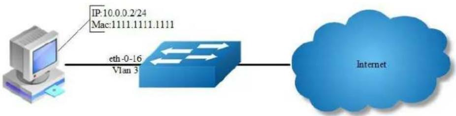
flowchart
graph LR
A["Computer"] -->|eth-0-16\nVlan 3| B["River"]
B --> C["Internet"]
Figure 7-14 ip source guard
step 1 Enter the configure mode
Switch# configure terminal
step 2 Enter the vlan configure mode and create vlan
Switch(config)# vlan database
Switch(config-vlan)# vlan 3
Switch(config-vlan)# exit
step 3 Enter the interface configure mode and set the attributes
Switch(config)# interface eth-0-16
Switch(config-if)# switchport
Switch(config-if)# no shutdown
Switch(config-if)# switchport access vlan 3
Switch(config-if)# exit
step 4 Add IP source guard entries
Switch(config)# ip source maximal binding number per-port 15
Switch(config)# ip source binding mac 1111.1111.1111 vlan 3 ip 10.0.0.2 interface eth-0-16
step 5 Enable IP source guard on the interface
Switch(config)# interface eth-0-16
Switch(config-if)# ip verify source ip
Switch(config-if)# exit
step 6 Allow forwarding of ARP packets
Switch(config)# arp as-layer-3 enable
step 7 Exit the configure mode
Switch(config)# exit
step 8 Validation
Switch#show running-config interface eth-0-16
!
interface eth-0-16
ip verify source ip
switchport access vlan 3
Remove ip source guard entries
Remove by entry:
Switch(config)# no ip source binding mac 1111.1111.1111 vlan 3 ip 10.0.0.2 interface eth-0-16
Remove by interface:
Switch(config)# no ip source binding entries interface eth-0-16
Remove by vlan:
Switch(config)# no ip source binding entries vlan 3
Remove all:
Switch(config)# no ip source binding entries
7.14.3 Application cases
N/A
7.15 Configuring Private-vlan
7.15.1 Overview
Function Introduction
Private-vlan a security feature which is used to prevent from direct l2 communication among a set of ports in a vlan.
It can provide a safer and more flexible network solutions by isolating the ports which in the same VLAN.
Principle Description
N/A
7.15.2 Configuration
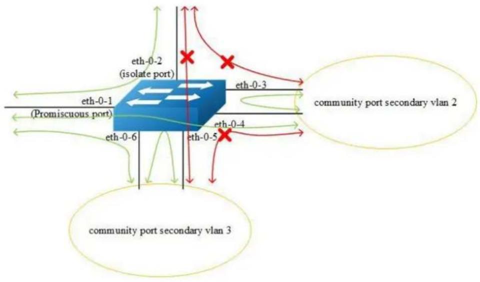
flowchart
graph TD
subgraph Community Port Secondary Vlan 2
eth0-1["(Promiscuous port)"] --> eth0-6["eth-0-6"]
eth0-2["(isolate port)"] --> eth0-3["eth-0-3"]
eth0-4["eth-0-4"] --> eth0-5["eth-0-5"]
end
subgraph Community Port Secondary Vlan 3
eth0-6 --> eth0-1["(Promiscuous port)"]
eth0-1 --> eth0-2["(isolate port)"]
eth0-2 --> eth0-3["eth-0-3"]
eth0-3 --> eth0-4["eth-0-4"]
eth0-4 --> eth0-5["eth-0-5"]
end
eth0-1 --> eth0-2
eth0-2 --> eth0-3
eth0-3 --> eth0-4
eth0-4 --> eth0-5
eth0-5 --> eth0-1
eth0-1 --> eth0-2
eth0-2 --> eth0-3
eth0-3 --> eth0-4
eth0-4 --> eth0-5
Figure 7-15 private vlan
As the figure above shows:
All ports are in a same primary vlan.
Port 1 is promiscuous port; it can communicate with all other ports.
Port 2 is isolate port; it cannot communicate with all other ports except for the promiscuous port (port 1).
Port 3 and port 4 are community ports in secondary vlan 2; they can communicate with each other. They cannot communicate with all other ports except for the promiscuous port.
Port 5 and port6 are community ports in secondary vlan 3; they can communicate with each other. They cannot communicate with all other ports except for the promiscuous port.
step 1 Enter the configure mode
Switch# configure terminal
step 2 Enter the vlan configure mode and create vlan
Switch (config)# vlan database
Switch (config-vlan)# vlan 2
Switch (config-vlan)# quit
step 3 Enter the interface configure mode and set the attributes
Promiscuous port: promiscuous port in pvlan can communicate with any other ports in this pvlan
Switch (config)# interface eth-0-1
Switch (config-if)# switchport mode private-vlan promiscuous
Switch (config-if)# switchport private-vlan 2
Switch (config-if)# quit
Isolate port: isolate port in pvlan can only communicate with promiscuous port in this pvlan
Switch (config)# interface eth-0-2
Switch (config-if)# switchport mode private-vlan host
Switch (config-if)# switchport private-vlan 2 isolate
Switch (config-if)# quit
Community port: community port in pvlan can communicate with promiscuous port and community ports with same community-vlan id in this pvlan
Switch (config)# interface eth-0-3
Switch (config-if)# switchport mode private-vlan host
Switch (config-if)# switchport private-vlan 2 community-vlan 2
Switch (config-if)# quit
Switch (config)# interface eth-0-4
Switch (config-if)# switchport mode private-vlan host
Switch (config-if)# switchport private-vlan 2 community-vlan 2
Switch (config-if)# quit
Switch (config)# interface eth-0-5
Switch (config-if)# switchport mode private-vlan host
Switch (config-if)# switchport private-vlan 2 community-vlan 3
Switch (config-if)# quit
Switch (config)# interface eth-0-6
Switch (config-if)# switchport mode private-vlan host
Switch (config-if)# switchport private-vlan 2 community-vlan 3
Switch (config-if)# quit
step 4 Exit the configure mode
Switch(config)# exit
step 5 Validation
The result of show private-vlan is as follows:
switch # show private-vlan
Primary Secondary Type Ports
2 N/A promiscuous eth-0-1
2 N/A islocate eth-0-2
2 2 community eth-0-3 eth-0-4
2 3 community eth-0-5 eth-0-6
7.15.3 Application cases
N/A
7.16 Configuring AAA
7.16.1 Overview
Function Introduction
Authentication verifies users before they are allowed access to the network and network services. System can use AAA authentication methods and Non-AAA authentication methods. RADIUS Authentication is one of AAA authentication methods. RADIUS is a distributed client/server system that secures networks against unauthorized access. RADIUS is widely used protocol in network environments. It is commonly used for embedded network devices such as routers, modem servers, switches, etc. RADIUS clients run on support routers and switches.
Clients send authentication requests to a central RADIUS server, which contains all user authentication and network service access information.
Principle Description
N/A
7.16.2 Configuration
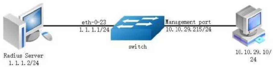
flowchart
graph LR
A["Radius Server\n1.1.1.2/24"] -->|eth-0-23\n1.1.1.1/24| B["switch"]
B -->|Management port\n10.10.29.215/24| C["Computer\n10.10.29.10/24"]
Figure 7-16 private vlan
The figure above is the networking topology for RADIUS authentication functions. We need one Switch and two computers for this test.
One computer as RADIUS server, it ip address of the eth0 interface is 1.1.1.2/24.
Switch has RADIUS authentication function. The ip address of interface eth-0-23 is 1.1.1.1/24. The management ip address of switch is 10.10.29.215, management port is connected the PC for test login, PC's ip address is 10.10.29.10.
step 1 Enter the configure mode
Switch# configure terminal
step 2 Enable AAA
Switch(config)# aaa new-model Switch(config)# aaa authentication login radius-login radius local
step 3 Configure Radius server
Switch(config)# radius-server host 1.1.1.2 auth-port 1819 key keyname Switch(config)# radius-server host 2001:1000::1 auth-port 1819 key keyname
step 4 Configure a layer 3 interface and set ip address
Switch(config)# interface eth-0-23
Switch(config-if)# no switchport
Switch(config-if)# ip address 1.1.1.1/24
Switch(config-if)# quit
step 5 set authentication mode
Switch(config)# line vty 0 7
Switch(config-line)# login authentication radius-login
Switch(config-line)# privilege level 4
Switch(config-line)# no line-password
step 6 Exit the configure mode
Switch(config-line)# end
step 7 Validation
You can use command show authentication status in switch:
Switch# show aaa status
aaa status:
Authentication enable
You can use command show keys in switch:
Switch# show aaa method-lists authentication
authen queue=AAA_ML_AUTHEN_LOGIN
Name = default state = ALIVE : local
Name = radius-login state = ALIVE : radius local
Telnet output:
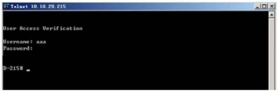
Figure 7-17 Telnet connecting test

NOTE
Don't forget to turn RADIUS authentication feature on.
Make sure the cables is linked correctly You can use command to check log messages if Switch can't do RADIUS authentication:
Switch# show logging buffer
7.16.3 Application cases
Radius server configuration (Using WinRadius for example)
Set ip address for PC:
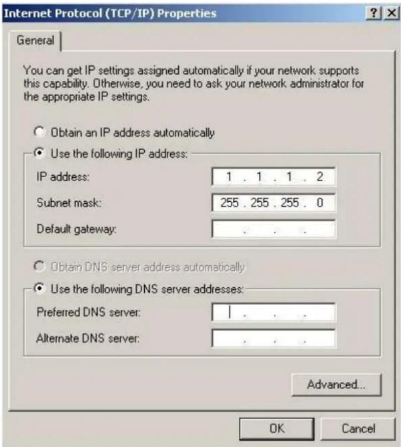
Figure 7-18 Set IP address for PC
Connectivity test between server and switch:
![C:\WINDOWS\system32\cmd.exe Microsoft Windows XP [Version 5.1.2600] (C) Copyright 1985-2001 Microsoft Corp. C:\Documents and Settings\Mac>ping 1.1.1.1 Pinging 1.1.1.1 with 32 bytes of data: Reply from 1.1.1.1: bytes=32 time=1ns TTL=64 Reply from 1.1.1.1: bytes=32 time<1ns TTL=64 Reply from 1.1.1.1: bytes=32 time<1ns TTL=64 Reply from 1.1.1.1: bytes=32 time<1ns TTL=64 Ping statistics for 1.1.1.1: Packets: Sent = 4, Received = 4, Lost = 0 (0% loss), Approximate round trip times in milli-seconds: Minimum = 0ms, Maximum = 1ns, Average = 0ms C:\Documents and Settings\Mac>](/content/2026/05/1140186/images/89805ddb5830fa826df3d376c44f47f5d3942bf606301f7cfdd461203b150d8f.jpg)
Figure 7-19 Connectivity test
Open winRadius:

Figure 7-20 WinRadius
Configurations for winRadius:
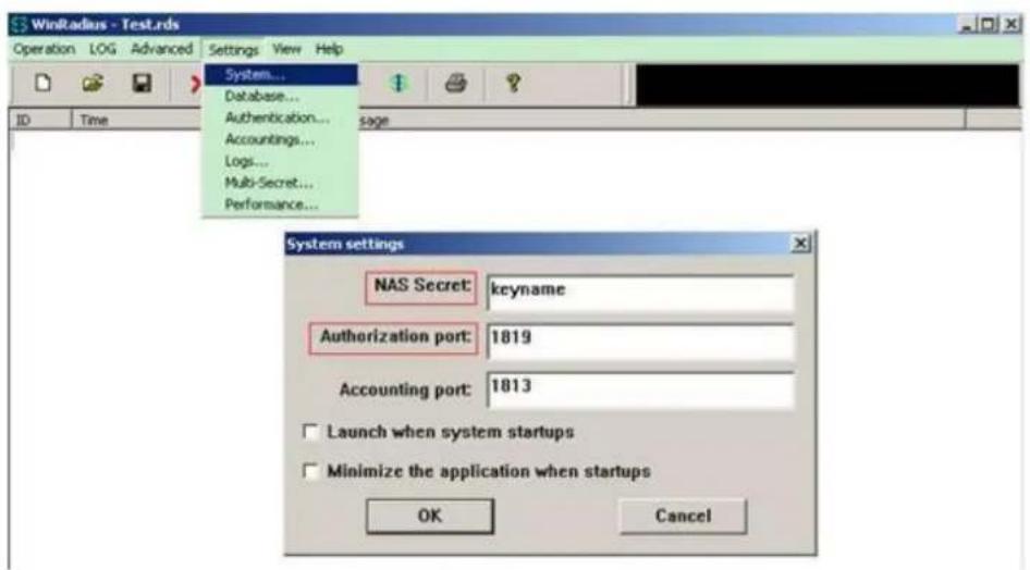
Figure 7-21 WinRadius
Add user and password:
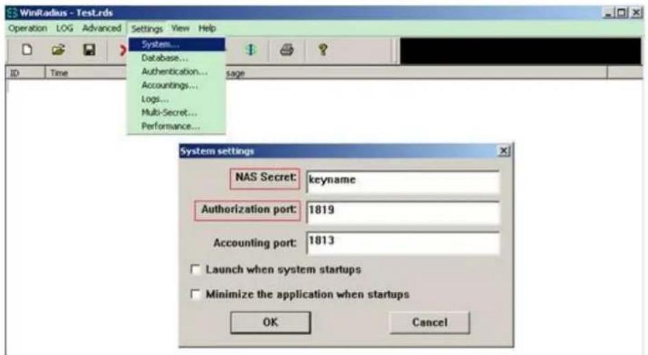
Figure 7-22 Add user and password
Connectivity test between client and switch:
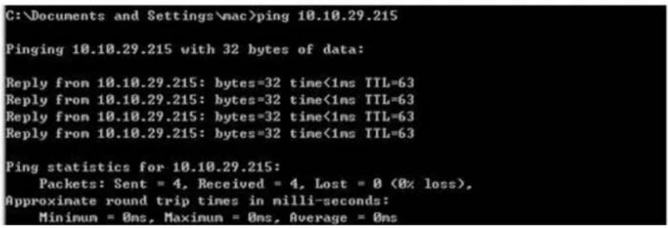
Figure 7-23 Connectivity test
7.17 Configuring TACACS+
7.17.1 Overview
Function Introduction
Authentication verifies users before they are allowed access to the network and network services. System can use AAA authentication methods and Non-AAA authentication methods. TACACS+ Authentication is one of AAA authentication methods. TACACS+ is a distributed client/server system that secures networks
against unauthorized access. TACACS+ is widely used protocol in network environments. It is commonly used for embedded network devices such as routers, modem servers, switches, etc. TACACS+ clients run on support routers and switches. Clients send authentication requests to a central TACACS+ server, which contains all user authentication and network service access information.
Principle Description
N/A
7.17.2 Configuration
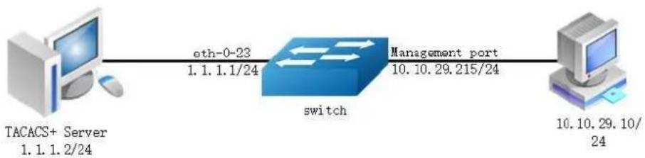
flowchart
graph LR
A["TACACS+ Server\n1.1.1.2/24"] -->|eth-0-23\n1.1.1.1/24| B["switch"]
B -->|Management port\n10.10.29.215/24| C["Computer\n10.10.29.10/24"]
Figure 7-24 TACACS+
The figure above is the networking topology for TACACS+ authentication functions. We need one Switch and two computers for this test. One computer as TACACS+ server, it ip address of the eth0 interface is 1.1.1.2/24. Switch has TACACS+ authentication function. The ip address of interface eth-0-23 is 1.1.1.1/24. The management ip address of switch is 10.10.29.215, management port (only in-band management port) is connected the PC for test login, PC's ip address is 10.10.29.10
step 1 Enter the configure mode
Switch# configure terminal
step 2 Enable AAA
Switch# configure terminal
Switch(config)# aaa new-model
Switch(config)# aaa authentication login tac-login tacacs-plus local
Switch(config)# aaa authorization exec default tacacs-plus
Switch(config)# aaa accounting exec default start-stop tacacs-plus
Switch(config)# aaa accounting commands default tacacs-plus
step 3 Configure tacacs+ server
Switch(config)# tacacs-server host 1.1.1.2 port 123 key keyname primary
step 4 Configure a layer 3 interface and set ip address
Switch(config)# interface eth-0-23
Switch(config-if)# no switchport
Switch(config-if)# ip address 1.1.1.1/24
Switch(config-if)# quit
step 5 set authentication mode
Switch(config)# line vty 0 7
Switch(config-line)# login authentication tac-login
Switch(config-line)# privilege level 4
Switch(config-line)# no line-password
step 6 Exit the configure mode
Switch(config-line)# end
step 7 Validation
You can use command show authentication status in switch:
Switch# show aaa status
aaa stats:
Authentication enable
You can use command show keys in switch:
Switch# show aaa method-lists authentication
authen queue=AAA_ML_AUTHEN_LOGIN
Name = default state = ALIVE : local
Name = tac-login state = ALIVE : tacacs-plus local
Telnet output:
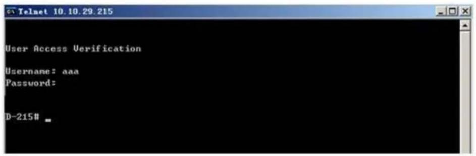
Figure 7-25 Telnet connecting test
7.17.3 Application cases
Radius server configuration
Download TACACS+ server code, DEVEL.201105261843.tar.bz2.
Build the TACACS+ server.
Add username and password in configure file.
#!/obj.linux-2.6.9-89.29.1.elsmp-x86_64/tac_plus
id = spawn {
listen = { port = 49 }
spawn = {
instances min = 1
instances max = 10
}
background = no
}
user = aaa {
password = clear bbb
member = guest
}
Run TACACS+ server:
[disciple: ~]$ ./tac_plus ./tac_plus.cfg.in -d 1
Use Ping command for test on PC:
C:\Documents and Settings\mac>ping 10.10.29.215
Pinging 10.10.29.215 with 32 bytes of data:
Reply from 10.10.29.215: bytes=32 time<1ns TTL=63
Reply from 10.10.29.215: bytes=32 time<1ns TTL=63
Reply from 10.10.29.215: bytes=32 time<1ns TTL=63
Reply from 10.10.29.215: bytes=32 time<1ns TTL=63
Ping statistics for 10.10.29.215:
Packets: Sent = 4, Received = 4, Lost = 0 (0% loss),
Approximate round trip times in milli-seconds:
Minimum = 0ns, Maximum = 0ns, Average = 0ns
Figure 7-26 Connectivity test
7.18 Configuring Port Isolate
7.18.1 Overview
Function Introduction
Port-isolation a security feature which is used to prevent from direct l2/l3 communication among a set of ports.
It can provide a safer and more flexible network solutions by isolating the ports which in the same VLAN.
Generally, it's used as an access device for user isolation.
Principle Description
N/A
7.18.2 Configuration
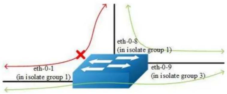
flowchart
graph TD
A["eth-0-1\n(in isolate group 1)"] --> B((Network Node))
C["eth-0-8\n(in isolate group 1)"] --> B
D["eth-0-9\n(in isolate group 3)"] --> B
B --> E["Outward Arrow"]
style B fill:#666,stroke:#333,stroke-width:2px
Figure 7-27 Port Isolate
The figure above is the basic topology for port-isolate.
Port 1 and port 8 are in the same isolate group 1, they are isolated. So port1 can not communicate with port 8. Port 9 is in a different isolate group 3, so port 9 can communicate with port 1 and port 8.
step 1 Enter the configure mode
Switch# configure terminal
step 2 Set the port isolate mode globally
The mode “l2” means only layer 2 packets are isolated. The mode “all” means all packet are isolated include the packets forward according to layer 3 routes.
Switch(config)# port-isolate mode 12
step 3 Enter the interface configure mode and set isolate group
Switch(config-if)# interface eth-0-1
Switch(config-if)# port-isolate group 1
Switch(config-if)# exit
Switch(config)# interface eth-0-8
Switch(config-if)# port-isolate group 1
Switch(config-if)# exit
Switch(config)# interface eth-0-9
Switch(config-if)# port-isolate group 3
Switch(config-if)# exit
step 4 Exit the configure mode
Switch(config)# end
step 5 Validation
Use the following command to display the port isolate groups:
switch# show port-isolate
Port Isolate Groups:
Groups ID: 1
eth-0-1, eth-0-8
Groups ID: 3
eth-0-9
7.18.3 Application cases
N/A
7.19 Configuring DDoS
7.19.1 Overview
Function Introduction
A denial-of-service attack (DoS attack) or distributed denial-of-service attack (DDoS attack) is an attempt to make a computer resource unavailable to its intended users. Although the means to carry out, motives for, and targets of a DoS attack may vary, it generally consists of the concerted efforts of a person or people to prevent an Internet site or service from functioning efficiently or at all, temporarily or indefinitely. Perpetrators of DoS attacks typically target sites or services hosted on high-profile web servers such as banks, credit card payment gateways, and even root name servers. The term is generally used with regards to computer networks, but is not limited to this field, for example, it is also used in reference to CPU resource management.
DDoS prevent is a feature which can protect our switch from follow kinds of denial-of-service attack and intercept the attack packets.
The flowing types are supported:
ICMP flood: attackers overwhelm the victim with ICMP packets.
Smurf attack: attackers flood a target system via spoofed broadcast ping messages.
SYN flood: attackers send a succession of SYN requests to a target's system.
UDP flood: attackers send a large number of UDP packets to random ports on a remote host.
Fraggle attack:attackers send a large number of UDP echo traffic to IP broadcast addresses, all fake source address.
Small-packet: attackers send a large number of small packets to the system util the resource exhaust.
bad mac intercept: attackers send packets with same source and destination MAC address.
bad ip equal: attackers send packets with same source and destination IP address.
Principle Description
N/A
7.19.2 Configuration
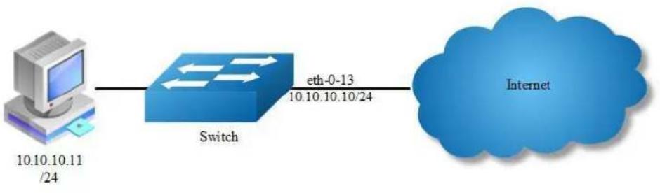
flowchart
graph LR
A["Computer 10.10.10.11 /24"] --> B["Switch"]
B --> C["eth-0-13 10.10.10.10/24"]
C --> D["Internet"]
Figure 7-28 Topology for DDoS test
step 1 Enter the configure mode
Switch# configure terminal
step 2 Set DDoS
Enable ICMP flood intercept and set the max received ICMP packet rate 100 packets per-second
Switch(config)# ip icmp intercept maxcount 100
Enable UDP flood intercept and set the max received UDP packet rate 100 packets per-second
Switch(config)# ip udp intercept maxcount 100
Enable Smurf attack intercept
Switch(config)# ip smurf intercept
Enable SYN flood intercept and set the max received SYN packet rate 100 packets per-second
Switch(config)# ip tcp intercept maxcount 100
Enable Fraggle attack intercept
Switch(config)# ip fraggle intercept
Enable Small-packet attack intercept and set the received packet length is be more than or equal to 32
Switch(config)# ip small-packet intercept maxlength 32
Enable packet source IP equals destination IP intercept
Switch(config)# ip ipeq intercept
Enable packet source MAC equals destination MAC intercept
Switch(config)# ip maceq intercept
step 3 Exit the configure mode
Switch(config)# end
step 4 Validation
Switch# show ip-intercept config Current DDoS Prevent configuration:
ICMP Flood Intercept :Enable Maxcount:500
UDP Flood Intercept :Enable Maxcount:500
SYN Flood Intercept :Enable Maxcount:500
Small-packet Attack Intercept :Enable Packet Length:45
Smurf Attack Intercept :Enable
Fraggle Attack Intercept :Enable
MAC Equal Intercept :Enable
TP Equal Intercept :Enable
Switch# show ip-intercept statistics
Current DDoS Prevent statistics:
Resist Small-packet Attack packets number : 1730
Resist ICMP Flood packets number : 0
Resist SYN Flood packets number : 0
Resist Fraggle Attack packets number : 0 Resist UDP Flood packets number : 0
Current DDoS Prevent mgmt-if statistics:
Resist ICMP Flood packets number : 0
Resist SYN Flood packets number : 0
Resist Fraggle Attack packets number : 0 Resist
UDP Flood packets number : 0
7.19.3 Application cases
N/A
7.20 Configuring Key Chain
7.20.1 Overview
Function Introduction
Keychain is a common method of authentication to configure shared secrets on all the entities, which exchange secrets such as keys before establishing trust with each other. Routing protocols and network applications often use this authentication to enhance security while communicating with peers.
The keychain by itself has no relevance; therefore, it must be used by an application that needs to communicate by using the keys (for authentication) with its peers. The keychain provides a secure mechanism to handle the keys and rollover based on the lifetime.
If you are using keys as the security method, you must specify the lifetime for the keys and change the keys on a regular basis when they expire. To maintain stability, each party must be able to store and use more than one key for an application at the same time. A keychain is a sequence of keys that are collectively managed for authenticating the same peer, peer group, or both. Keychain groups a sequence of keys together under a keychain and associates each key in the keychain with a lifetime.
Principle Description
N/A
7.20.2 Configuration
step 1 Enter the configure mode
Switch# configure terminal
step 2 Create key chain and set key
Switch(config)# key chain test
Switch(config-keychain)# key 1
Switch(config-keychain-key)# key-string ##test_keystring_1##
Switch(config-keychain-key)# accept-lifetime 0:0:1 1 jan 2012 infinite
Switch(config-keychain)# key 2
Switch(config-keychain-key)# key-string ##test_keystring_2##
Switch(config-keychain-key)# send-lifetime 0:0:1 2 jan 2012 infinite
step 3 Exit the configure mode
Switch(config)# end
step 4 Validation
To display the keychain configuration, use the command show key chain in the privileged EXEC mode"
Switch # show key chain
key chain test:
key 1 -- text "key-string ##test_keystring_1###
accept-lifetime <00:00:01 Jan 01 2012> - <infinite>
send-lifetime <always valid> - <always valid> [valid now]
key 2 -- text "key-string ##test_keystring_2###
accept-lifetime <always valid> - <always valid> [valid now]
send-lifetime <00:00:01 Jan 02 2012> - <infinite>
7.20.3 Application cases
N/A
7.21 Configuring Port-Block
7.21.1 Overview
Function Introduction
By default, the switch floods packets with unknown destination MAC addresses out of all ports. If unknown unicast and multicast traffic is forwarded to a protected port, there could be security issues. To prevent unknown unicast or multicast traffic from being forwarded from one port to another, you can block a port (protected or unprotected) from flooding unknown unicast or multicast packets to other ports.
Principle Description
N/A
7.21.2 Configuration
step 1 Enter the configure mode
Switch# configure terminal
step 2 Enter the interface configure mode and block unknown unicast
Switch(config)# interface eth-0-1
Switch(config-if)# port-block unknown-unicast
Switch(config-if)# exit
step 3 Exit the configure mode
Switch(config)# end
step 4 Validation
To display the port-block configuration, use the command show port-block in the privileged EXEC mode:
Switch # show port-block interface eth-0-1
Known unicast blocked: Enabled
Known multicast blocked: Disabled
Unknown unicast blocked: Disabled
Unknown multicast blocked: Disabled
Broadcast blocked: Disabled
7.21.3 Application cases
N/A
8 Device Management Configuration Guide
8.1 Configuring STM
8.1.1 Overview
Function Introduction
Switch Table Management (STM) is used to configure system resources in the switch to optimize support for specific features, depending on how the switch is used in the network.
You can select a profile to provide maximum system usage for some functions; for example, use the default profile to balance resources and use vlan profile to obtain max MAC entries.
To allocate ternary content addressable memory (TCAM) resources for different usages, the switch STM profile prioritize system resources to optimize support for certain features. You can select STM templates to optimize these features:
layer2: The VLAN template supports the maximum number of unicast MAC addresses. It would typically be selected for a Layer 2 switch.
layer3: The routing template maximizes system resources for unicast routing, typically required for a router or aggregator in the center of a network.
ipv6: The ipv6 template, support the ipv6 functions.
default: The default template gives balance to all functions.

When users configured a profile mode which is not exist in the next reboot then default hardware configure will be used when system up with the next image. The hardware configure may be different from the default profile.
Principle Description
N/A
8.1.2 Configuration
Follow these guidelines when selecting and configuring STM profiles.
You must reload the switch for the configuration to take effect.
Use the “stm prefer layer2” global configuration command only on switches intended for Layer 2 switching with no routing.
Do not use the layer3 profile if you do not have routing enabled on your switch. The stm prefer layer3 global configuration command prevents other features from using the memory allocated to IPv4 unicast routing in the routing profile.
step 1 Enter the configure mode
Switch# configure terminal
step 2 Set STM profile(use layer3 for example)
Switch(config)# stm prefer layer3
step 3 Exit the configure mode
Switch(config)# end
step 4 Validation
This is an example of an output display for route template:
Switch# show stm prefer
Current profile is :default
number of vlan instance : 1/4094
number of unicast mac address : 0/65536
number of multicast mac address : 0/2048
number of blackhole mac address : 0/128
number of max applied vlan mapping : 0/1024
number of bfd sessions : 0/128
number of CFM load&remote MEPs : 0/1024
number of CFM lm : 0/256
number of CFM lck : 0/24
number of G8031 groups : 0/256
number of G8032 rings : 0/256
number of G8032 member ports : 0/256
number of mac based vlan class : 0/512
number of ipv4 based vlan class : 0/512
number of ipv6 based vlan class : 0/0
number of dotlx mac based : 0/2048
number of unicast ipv4 host routes : 0/4096
number of unicast ipv4 indirect routes : 0/8192
number of unicast ipv4 policy based routes : 0/16
number of unicast ipv6 host routes : 0/0
number of unicast ipv6 indirect routes : 0/0
number of unicast ecmp groups : 0/240
number of unicast ip tunnel peers : 0/8
number of multicast ipv4 routes : 0/1023
number of myr entries : 0/511
number of myr6 entries : 0/0
number of multicast ipv6 routes : 0/0
number of ipv4 source guard entries : 0/1024
number of ingress port acl flow entries : 0/2035
number of ingress vlan acl flow entries : 0/255
number of egress port acl flow entries : 0/255
number of ingress port qos flow entries : 9/2043
number of ingress port acl ipv6 flow entries : 0/0
number of ingress vlan acl ipv6 flow entries : 0/0
number of egress port acl ipv6 flow entries : 0/0
number of ingress port qos ipv6 flow entries : 0/0
number of link aggregation (static & lacp) : 0/55
number of ipfix cache : 0/16384
The profile stored for use after the next reload is the layer3 profile.
step 5 Reboot the device
Switch# reload
8.1.3 Application cases
N/A
8.2 Configuring syslog
8.2.1 Overview
Function Introduction
The system message logging software can save messages in a log file or direct the messages to other devices. The system message logging facility has these features:
Provides you with logging information for monitoring and troubleshooting.
- Allows you to select the types of logging information that is captured.
- Allows you to select the destination of the captured logging information.
By default, the switch logs normal but significant system messages to its internal buffer and sends these messages to the system console. You can specify which system messages should be saved based on the type of the severity level. The messages are time-stamped to enhance real-time debugging and management.
You can access the logged system messages using the switch command-line interface (CLI) or by saving them to a properly configured log server. The switch software saves the log messages in an internal buffer that can store up to 1000 messages. You can monitor the system messages remotely by accessing the switch through Telnet or the console port, or by viewing the logs on a log server.
Principle Description
Terminology:
| Terminology | Description |
| Logging | Current logging configuration |
| Show | Show logging configuration |
| Levels | Severity level information |
| Enable | Enable write log to local file |
| Disable | Disable write log to local file |
System Message Log Facility Types:
| Facility Name | Definition |
| kern | kernel messages |
| user | random user-level messages |
| mail system | |
| daemon | system daemons |
| auth | security/authorization messages |
| syslog | messages generated internally by syslogd |
| lpr | line printer subsystem |
| news | network news subsystem |
| uucp | UUCP subsystem |
| cron | clock daemon |
| authpriv | security/authorization messages (private) |
| ftp | ftp daemon |
Severity Level Definitions:
| Severity Level | Definition |
| emergency | system is unusable |
| alert | action must be taken immediately |
| critical | critical conditions |
| error | error conditions |
| warning | warning conditions |
| notice | normal but significant condition |
| information | Informational |
| debug | debug-level messages |
8.2.2 Configuration
Configuring Logging server
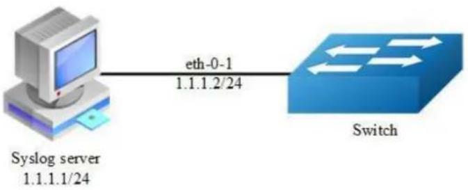
flowchart
graph LR
A["Syslog server 1.1.1.1/24"] -->|eth-0-1 1.1.1.2/24| B["Switch"]
Figure 8-1 syslog server
step 1 Enter the configure mode
Switch# configure terminal
step 2 Enable logging server and set the attributes
Switch(config)# logging server enable
Switch(config)# logging server address 1.1.1.1
Switch(config)# logging server address 2001:1000::2
Switch(config)# logging server severity debug
Switch(config)# logging server facility mail
step 3 Exit the configure mode
Switch(config)# end
step 4 Validation
Switch# show logging
Current logging configuration:
logging buffer 500
logging timestamp bsd
logging file enable
logging level file warning
logging level module debug
logging server enable
logging server severity debug
logging server facility mail
logging server address 1.1.1.1
logging server address 2001:1000::2
logging alarm-trap enable
logging alarm-trap level middle
logging merge enable
logging merge fifo-size 1024
logging merge timeout 10
logging operate disable
Configuring Logging Buffer Size
By default, the number of messages to log to the logging buffer is 500. If desired, you can set the number between 10 and 1000.
step 1 Enter the configure mode
Switch# configure terminal
step 2 Set the logging Buffer Size
Switch(config)# logging buffer 700
step 3 Exit the configure mode
Switch(config)# end
step 4 Validation
Switch# show logging
Current logging configuration:
logging buffer 700
logging timestamp bsd
logging file enable
logging level file warning
logging level module debug
logging server enable
logging server severity debug
logging server facility mail
logging server address 1.1.1.1
logging alarm-trap enable
logging alarm-trap level middle
logging merge enable
logging merge fifo-size 1024
logging merge timeout 10
logging operate disable
The following is the information of logging server:
| Time | IP A... | Mog Type | Message |
| Apr 08 17:34:58 | 1.1.1.2 | mail.info | Apr 8 17:35:27 5-20B INTERFACE-6: interface eth-0-23 state change to up |
| Apr 08 17:34:58 | 1.1.1.2 | mail.warn | Apr 8 17:35:21 5-20B LOG-4i user=jp=10,10,30,226 cmdlevel=4,opresult=0shutdown |
| Apr 08 17:34:50 | 1.1.1.2 | mail.info | Apr 8 17:35:21 5-20B INTERFACE-6: interface eth-0-23 state change to down |
| Apr 08 17:34:54 | 1.1.1.2 | mail.warn | Apr 8 17:36:25 S-20B LOG-4i user=jp=10,10,30,226 cmdlevel=4,opresult=0.jno shu |
| Apr 08 17:34:48 | 1.1.1.2 | mail.warn | Apr 8 17:35:15 S-20B LOG-4i user=jp=10,10,30,226 cmdlevel=4,opresult=0.interface eth-0-23 |
| Apr 08 17:32:05 | 1.1.1.2 | mail.warn | Apr 8 17:36:37 S-20B LOG-4i user=jp=10,10,30,226 cmdlevel=4,opresult=0.interface eth-0-22 |
| Apr 08 17:31:58 | 1.1.1.2 | mail.warn | Apr 8 17:32:30 S-20B LOG-4i user=jp=10,10,30,226 cmdlevel=4,opresult=0.jlogging server facility n |
| Apr 08 17:31:52 | 1.1.1.2 | local7.info | Apr 8 17:32:24 S-20B INTERFACE-6: interface eth-0-22 state change to up |
| Apr 08 17:31:50 | 1.1.1.2 | local7.warn | Apr 8 17:32:22 S-20B LOG-4i user=jp=10,10,30,226 cmdlevel=4,opresult=0.jno shutdown |
| Apr 08 17:31:45 | 1.1.1.2 | local7.warn | Apr 8 17:32:17 S-20B LOG-4i user=jp=10,10,30,226 cmdlevel=4,opresult=0.shutdown |
| Apr 08 17:31:44 | 1.1.1.2 | local7.warn | Apr 8 17:36:15 S-20B LOG-4i user=jp=10,10,30,226 cmdlevel=4,opresult=0.interface eth-0-22 |
| Apr 08 17:30:30 | 1.1.1.2 | syslog.warn | Apr 8 17:31:02 S-20B LOG-4i user=jp=10,10,30,226 cmdlevel=4,opresult=0.jlogging server facility s |
| Apr 08 17:29:56 | 1.1.1.2 | syslog.warn | Apr 8 17:30:27 S-20B LOG-4i user=jp=10,10,30,226 cmdlevel=4,opresult=0.shutdown |
| Apr 08 17:29:56 | 1.1.1.2 | syslog.info | Apr 8 17:30:27 S-20B INTERFACE-6: interface eth-0-22 state change to down |
| Apr 08 17:29:54 | 1.1.1.2 | syslog.warn | Apr 8 17:30:25 S-20B LOG-4i user=jp=10,10,30,226 cmdlevel=4,opresult=0.interface eth-0-22 |
| Apr 08 17:27:51 | local | user info | Listening for Syslog messages on IP address: 1.1.1.1 |
| Apr 08 17:27:30 | local | user info | Stopped Syslog server |
| Apr 08 16:43:48 | local | user info | Listening for Syslog messages on IP address: 1.1.1.1 |
| Apr 08 16:42:45 | local | user info | Stopped Syslog server |
| Apr 08 16:42:01 | local | user info | Listening for Syslog messages on IP address: 1.1.1.1 |
| Apr 08 16:41:55 | local | user info | Stopped Syslog server |
| Apr 08 16:40:59 | local | user info | Listening for Syslog messages on IP address: 1.1.1.1 |
| Apr 08 16:40:33 | local | user info | Stopped Syslog server |
| Apr 08 16:35:07 | local | user info | Listening for Syslog messages on IP address: 1.1.1.1 |
Figure 8-2 syslog on server

NOTE
You can use command to check showing Logging Information.
When configuring the syslog Servers, make sure the cables is linked correctly and two computers can ping each other. Before you can send the system log messages to a log server, you must configure Syslog Software, at the end you can see the log from your software.
8.2.3 Application cases
N/A
8.3 Configuring mirror
8.3.1 Overview
Function Introduction
Mirror function can send one or more copies of packets which are passing through the ports/vlans or sending and receiving by CPU to one or more specified destination ports. It can also send the copies to the CPU and keep in memory or flash files.
The copies of the packets are used for network analyze. The mirror function does not affect the original network traffic.
Principle Description
The following describes concepts and terminology associated with mirror configuration:
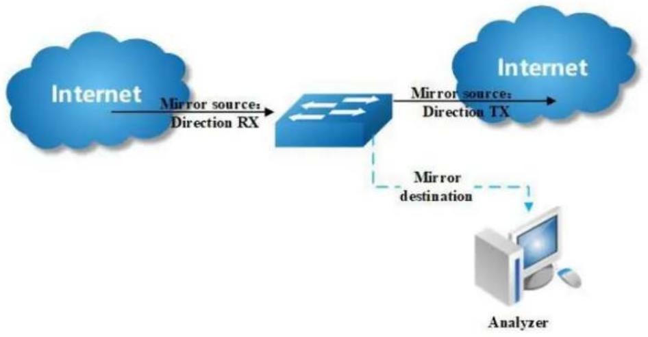
flowchart
graph TD
A["Internet"] -->|Mirror source: Direction RX| B["Router"]
B -->|Mirror source: Direction TX| C["Internet"]
B -.->|Mirror destination| D["Analyzer"]
Figure 8-3 Mirror
1. Mirror session
A mirror session is an association of a mirror destination with one or more mirror source. The mirror destination and mirror source will describe later.
The device supports up to 3 mirror sessions.
Mirror sessions do not interfere with the normal operation of the switch. However, an oversubscribed mirror destination, for example, a 10-Gbps port monitoring a 100-Gbps port, results in dropped or lost packets.
2. Mirror direction
The device supports to set the direction of the mirror source, there are 3 options for choose: TX/RX/BOTH.
Receive (RX) mirror: The goal of receive (or ingress) mirror is to monitor as much as possible packets received by the source interface or VLAN before any modification or processing is performed by the switch. A copy of each packet received (except these packets: BPDU, LACPDU, BMGPDU, packets have been discarded by IP-MAC binding check for Vlan_based mirror, CRC error packets for both Port_based and vlan_based mirror) by the source is sent to the destination
port for that mirror session. You can monitor a series or range of ingress ports or VLANs in a mirror session. Packets that are modified because of routing are copied without modification; that is, the original packet is copied. Packets that are modified because of quality of service (QoS)—for example, modified Differentiated Services Code Point (DSCP)—are copied with modification. Packets that are modified because of VLAN translation or VLAN classification is copied with the modification. Some features that can cause a packet to be dropped during receive processing have no effect on mirror, the destination port can receive a copy of the packet even if the actual incoming packet is dropped. These features include ingress ACL, VLAN's ingress filter, MAC filter, STP, VLAN tag control, port security, unknown routing packets.
Transmit (TX) mirror: The goal of transmit (or egress) mirror is to monitor as much as possible packets sent by the source interface after all modification and processing is performed by the switch. A copy of each packet (except these packets: packets from CPU port for Vlan_based mirror, mirroring packets for both Port_based and vlan_based mirror) sent by the source is sent to the destination port for that mirror session. Some features that can cause a packet to be dropped during transmit processing might have affect on mirror.
Both: In a mirror session, you can monitor a single port for both received and sent packets.
3. Mirror source
The Mirror source is the original traffic of the network. The types of source are described as following:
Source port: A source port is a layer2 or layer 2 interface which need to be monitored. A physical port or link agg port can be a source port. The member of link agg port is not supported to be a mirror source.
Source VLAN: A source vlan is a vlan which need to be monitored. User should create a vlan interface before set a vlan as mirror source.
CPU:User can set CPU as mirror source to monitor the packets send to or receive from the CPU. The copies of packets send to the mirror destination are before cpu-traffic-limit process. Only session 1 support CPU as mirror source currently.
4. Mirror destination
Mirror function will copy the packets and sent the copies to the mirror destination.
The types of destination are described as following:
Local destination port: The destination port should be a physical port or link agg port, member of link agg port is not supported. The destination port has these characteristics:
It must reside on the same switch as the source port.
It should not be in "shutdown" state
It can participate in only one mirror session at a time (a destination port in one mirror session cannot be a destination port for a second mirror session).
It cannot be a source port.
The port does not transmit any traffic except that required for the mirror session.
It does not participate in spanning tree while the mirror session is active.
When it is a destination port, all other normal system function of this port should not work until mirror destination configure disabled on this port.
No address learning occurs on the destination port.
The real statues of the speed/duplex might not coincide with the values which are displayed.
Multi-destination: The device supports to use a group of destination ports to receive several copies of the traffic. The characteristics of each member in the group of destination ports are same as single destination port.
Remote destination : A remote mirror destination is a remote destination vlan, which has a specified out-going port. The copies of the packets should send to the specified port and add the tag of the remote vlan. A remote destination has these characteristics:
It is a vlan with a specified out going port.
The remote VLAN range should be 2 to 4094. If the VLAN isn't created in system, user can not configure this VLAN as mirror remote vlan.
The out going port should be a physical port. User should manually check if the out going port can transfer mirrored packets.
Monitor traffic packets are inserted a tag with the remote VLAN ID and directed over the specified out going port to the mirror destination session device.
It is recommended to configure remote mirror's destination port as switch port. Users should add the destination port to the remote vlan otherwise the mirrored packet can not be transmitted out.
CPU destination: send the copies of packet to the CPU of current device. If there is no analyzer available, user can use CPU as mirror destination and save the result for user or developers analyze packets.
You can analyze network traffic passing through ports or vlans by using mirror function to send a copy of the traffic to another port on the switch that has been connected to a Switch Probe device or other Remote Monitoring (RMON) probe or security device. However, when there is no other monitoring device for capturing packets, normal mirror destination to ports doesn't work. So we can set CPU as mirror destination to send a copy of the traffic to CPU for storing packets. It supports the cli to display the packets of mirror CPU and write the packets in a text file. It is a very functional debug tool. Mirror does not affect the switching of network traffic on source ports or source vlans; a copy of the packets received or sent by the source interfaces are sent to the destination CPU. The cpu-traffic-limit rate can be configured. CPU can participate as a destination in only one mirror session.
8.3.2 Configuration
Configuring Local port mirror
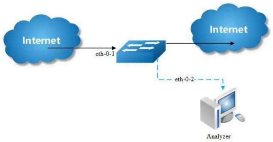
Figure 8-4 port Mirror
Copy the packets of eth-0-1 and send them to eth-0-2
step 1 Enter the configure mode
Switch# configure terminal
step 2 Set the destination of mirror
Switch(config)# interface eth-0-2
Switch(config-if)# no shutdown
Switch(config-if)# exit
Switch(config)# monitor session 1 destination interface eth-0-2
step 3 Set the source of mirror
Switch(config)# monitor session 1 source interface eth-0-1 both
step 4 Exit the configure mode
Switch(config)# end
step 5 Validation
Switch# show monitor session 1
Session 1
Status : Valid
Type : Local Session
Source Ports :
Receive Only :
Transmit Only :
Both : eth-0-1
Source VLANs :
Receive Only :
Transmit Only :
Both :
Destination Port : eth-0-2
Configuring local vlan mirror
Copy the packets from vlan 10 and send them to eth-0-2
step 1 Enter the configure mode
Switch# configure terminal
step 2 Set the destination of mirror
Switch(config)# interface eth-0-2
Switch(config-if)# no shutdown
Switch(config-if)# exit
Switch(config)# monitor session 1 destination interface eth-0-2
step 3 Enter the vlan configure mode and create a vlan
Switch(config)# vlan database
Switch(config-vlan)# vlan 10
Switch(config-vlan)# exit
step 4 Create a vlan interface
Switch(config)# interface vlan10
Switch(config-if)# exit
step 5 Set the source of mirror
Switch(config)# monitor session 1 source vlan 10 rx
step 6 Exit the configure mode
Switch(config)# end
step 7 Validation
Switch# show monitor session 1
Session 1
Status : Valid
Type : Local Session
Source Ports :
Receive Only :
Transmit Only :
Both :
Source VLANs :
Receive Only : 10
Transmit Only :
Both :
Destination Port : eth-0-2
Configuring CPU as mirror source
Copy the packets from or to CPU and send them to eth-0-2
step 1 Enter the configure mode
Switch# configure terminal
step 2 Set the destination of mirror
Switch(config)# interface eth-0-1
Switch(config-if)# no shutdown
Switch(config-if)# exit
Switch(config)# monitor session 1 destination interface eth-0-2
step 3 Set the source of mirror
Switch(config)# monitor session 1 source cpu both
step 4 Exit the configure mode
Switch(config)# end
step 5 Validation
DUT1# show monitor session 1
Session 1
Status : Valid
Type : Cpu Session
Source Ports :
Receive Only :
Transmit Only :
Both : cpu
Source VLANs :
Receive Only :
Transmit Only :
Both :
Destination Port :eth-0-1
Configuring Multi-destination Mirror
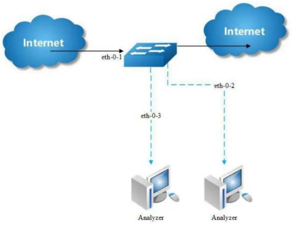
Figure 8-5 Multi-destination Mirror
Copy the packets of eth-0-1 and send them to eth-0-2 and eth-0-3
The rules of mirror source are same as single destination port. The following case use source port for example.
step 1 Enter the configure mode
Switch# configure terminal
step 2 Set the destination group of mirror
Switch(config)# interface eth-0-2
Switch(config-if)# no shutdown
Switch(config-if)# exit
Switch(config)# interface eth-0-3
Switch(config-if)# no shutdown
Switch(config-if)# exit
Switch(config)# monitor session 1 destination group 1
Switch(config-monitor-d-group)# member eth-0-2
Switch(config-monitor-d-group)# member eth-0-3
Switch(config-monitor-d-group)# exit
step 3 Set the source of mirror
Switch(config)# interface eth-0-1
Switch(config-if)# no shutdown
Switch(config-if)# exit
Switch(config)# monitor session 1 source interface eth-0-1
step 4 Exit the configure mode
Switch(config)# end
step 5 Validation
Session 1
Status : Valid
Type : Local Session
Source Ports :
Receive Only :
Transmit Only :
Both : eth-0-1
Source VLANs :
Receive Only :
Transmit Only :
Both :
Destination Port : eth-0-2 eth-0-3
Configuring Remote Mirror
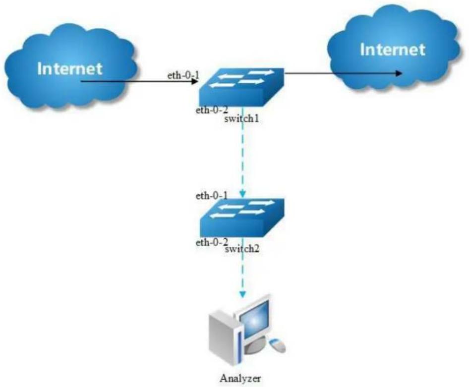
flowchart
graph TD
A["Internet"] -->|eth-0-1| B["Switch1"]
B -->|eth-0-2| C["Switch2"]
C --> D["Analyzer"]
Figure 8-6 Remote Mirror
If local device cannot connect to an analyzer directly, User can choose remote mirror to send the copies of packets with specified vlan tag.
The remote device can pick out the packets with this vlan for analyze.
The following example copies the packets form Switch1's eth-0-1, and send them to Switch2 via Switch1's eth-0-2. Switch2 sends these packets to the analyzer.
The configuration of Switch1:
step 1 Enter the configure mode
Switch# configure terminal
step 2 Set the destination of mirror
Switch(config)# vlan database
Switch(config-vlan)# vlan 15
Switch(config-vlan)# exit
Switch(config-if)# exit
Switch(config)# interface eth-0-2
Switch(config-if)# no shutdown
Switch(config-if)# switchport mode trunk
Switch(config-if)# switchport trunk allowed vlan add 15
Switch(config-if)# exit
Switch(config)# monitor session 1 destination remote vlan 15 interface eth-0-2
step 3 Set the source of mirror
Switch(config)# interface eth-0-1
Switch(config-if)# no shutdown
Switch(config)# monitor session 1 source interface eth-0-1 both
step 4 Exit the configure mode
Switch(config)# end
step 5 Validation
SwitchA# show monitor session 1
Session 1
Status : Valid
Type : Remote Session
Source Ports :
Receive Only :
Transmit Only :
Both : eth-0-1
Source VLANs :
Receive Only :
Transmit Only :
Both :
Destination Port : eth-0-2
Destination remote VLAN : 15
The configuration of Switch2:
Use these methods on Switch2 to send packets to analyzer via eth-0-2
method 1: use vlan 15 as mirror source, eth-0-2 as mirror destination
Switch # configure terminal
Switch (config)# vlan database
Switch (config-vlan)# vlan 15
Switch (config-vlan)# exit
Switch (config)# interface vlan15
Switch (config-if)# exit
Switch (config)# interface eth-0-2
Switch (config-if)# no shutdown
Switch (config)# interface eth-0-1
Switch (config-if)# no shutdown
Switch (config-if)# switchport mode trunk
Switch (config-if)# switchport trunk allowed vlan add 15
Switch (config-if)# exit
Switch (config)# monitor session 1 destination interface eth-0-2
Switch (config)# monitor session 1 source vlan 15 rx
Switch (config)# end
method 2: add both ports in to the same vlan (15), and make the packet flood in this vlan
Switch# configure terminal
Switch(config)# no spanning-tree enable
Switch(config)# vlan database
Switch(config-vlan)# vlan 15
Switch(config-vlan)# exit
Switch(config)# interface eth-0-2
Switch(config-if)# no shutdown
Switch(config-if)# switchport mode access
Switch(config-if)# switchport access vlan 15
Switch(config)# interface eth-0-1
Switch(config-if)# no shutdown
Switch(config-if)# switchport mode trunk
Switch(config-if)# switchport trunk allowed vlan add 15
Switch(config-if)# exit

NOTE
In this configuration vlan tag is stripped because eth-0-2 is access
method 3: flood in vlan and keep vlan tag 15
If user needs to keep the vlan tag 15, eth-0-2 should be trunk port: (other configurations are same as method 2)
Switch(config)# interface eth-0-2
Switch(config-if)# no shutdown
Switch(config-if)# switchport mode trunk
Switch(config-if)# switchport trunk allowed vlan add 15
Configuring CPU Mirror Dest
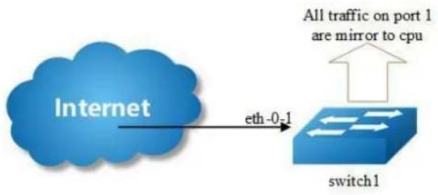
flowchart
graph LR
A["Internet"] -->|eth-0-1| B["switch1"]
B --> C["All traffic on port 1 are mirror to cpu"]
Figure 8-7 Mirror to cpu
step 1 Enter the configure mode
Switch# configure terminal
step 2 Set the destination of mirror
Switch(config)# monitor session 1 destination cpu
Set the buffer size and to cpu rate:
Switch(config)# monitor cpu set packet buffer 100
Switch(config)# cpu-traffic-limit reason mirror-to-cpu rate 128
step 3 Set the source of mirror
Switch(config)# monitor session 1 source interface eth-0-1 both
step 4 Exit the configure mode
Switch(config)# end
Optional steps
Enable or disable to write the packets in to the flash files.
Switch# monitor cpu capture packet start
Switch# monitor cpu capture packet stop
Exchange the files from *.txt to *.pcap
Switch# pcap convert flash:/mirror/MirCpuPkt-2016-02-05-18-31-13.txt
flash:/MirCpuPkt-2016-02-05.pcap
Set the action after the packet buffer is exceeded: “drop” means discard the latest packet; “replace” means discard the oldest packet.
Switch(config)# monitor cpu capture strategy drop
Switch(config)# monitor cpu capture strategy replace
step 5 Validation
This example shows how to set up a mirror session, session 1, for monitoring source port traffic to a destination cpu. You can use show monitor session to see the configuration.
Switch# show monitor session 1
DUT1# show monitor session 1
Session 1
Status : Valid
Type : Cpu Session
Source Ports :
Receive Only :
Transmit Only :
Both : eth-0-1
Source VLANs :
Receive Only :
Transmit Only :
Both :
Destination Port : cpu
This example shows how to display the mirror cpu packets
Switch# show monitor cpu packet all
----show all mirror to cpu packet info----
packet: 1
Source port: eth-0-1
MACDA:264e.ad52.d800, MACSA:0000.0000.1111
vlan tag:100
IPv4 Packet, IP Protocol is 0
IPDA:3.3.3.3, IPSA: 10.0.0.2
Data length: 47
Data:
264e ad52 d800 0000 0000 1111 8100 0064
0800 4500 001d 0001 0000 4000 6ad9 0a00
0002 0303 0303 6365 6c74 6563 796f 75
This example shows how to display the mirror buffer size:
Switch# show monitor cpu packet buffer
----show packet buffer size ----
The mirror-to-cpu packet buffer size of user set is: 100
This example shows how to display the mirror cpu traffic-limit rate:
Switch# show cpu traffic-limit | include mirror-to-cpu
mirror-to-cpu 128 0
This example shows how to display the files of the flash:
Switch# ls flash:/mirror
Directory of flash:/mirror
total 8
-rw-r---- 1 2287 Dec 23 01:16 MirCpuPkt-2016-12-23-01-15-54.txt
-rw-r---- 1 2568 Jan 3 11:41 MirCpuPkt-2017-01-03-11-41-33.txt
14.8T bytes total (7.9T bytes free)
Switch# more flash:/mirror/ MirCpuPkt-2017-01-03-11-41-33.txt
sequence srcPort
1 eth-0-1
+++++++1483443444:648884
8c 1d cd 93 51 00 00 00 00 00 11 11 08 00 45 00
00 26 00 01 00 00 40 00 72 d0 01 01 01 01 03 03
03 03 63 65 6e 74 65 63 79 6f 75 63 65 6e 74 65
63 79 6f 75
----
sequence srcPort
2 eth-0-1
+++++++1483443445:546440
8c ld cd 93 51 00 00 00 00 00 11 11 08 00 45 00
00 26 00 01 00 00 40 00 72 d0 01 01 01 01 03 03
03 03 63 65 e 74 65 63 79 f75 f65 f6e f74 f65
63 79 f75
This example shows how to display the files of the flash. *.pcap files can open with packets analyzer applications such as wireshark. Please referenc to the "ftp" and "tftp" part to download the files.
Switch#ls flash:/mirror
Directory of flash:/mirror
total 12
-rw-r---- 1 2287 Dec 23 01:16 MirCpuPkt-2016-12-23-01-15-54.txt
-rw-r---- 1 2568 Jan 3 11:41 MirCpuPkt-2017-01-03-11-41-33.txt
-rw-r--r-- 1 704 Jan 3 13:07 test.pcap
14.8T bytes total (7.9T bytes free)
This example shows how to display the actions after the buffer is full
Switch# show monitor cpu capture strategy
The capture strategy of cpu mirror is: replace (add new packet and remove oldest packet when buffer is full)
8.3.3 Application cases
N/A
8.4 Configuring Device Management
8.4.1 Overview
Function Introduction
User can manage the switch through the management port. The switch has two management ports: an Ethernet port and a console port.
Principle Description
N/A
8.4.2 Configuration
Configuring console port for management
The default console parameters of switch are:
Baud rate default is 115200.
Data bits default is 8.
➢ Stop bits default is 1.
Parity settings default is none.
Before you can assign switch information, make sure you have connected a PC or terminal to the console port, and configured the PC or terminal software parameters to match the default console port parameters. After login in the switch, you can modify the console parameters.
step 1 Enter the configure mode
Switch# configure terminal
step 2 Enter line configuration mode and set the console speed
Switch(config)# line console 0 Switch(config-line)# speed 19200
step 3 Exit the configure mode
Switch(config-line)# end
step 4 Validation
After the above setting, console port parameter has been changed, and the PC or terminal can't configure the switch by console port. You must update PC or terminal console speed from 115200 to 19200 to match the new console parameter and can continue configure the switch by console port.
Configuring out band Ethernet port for management
In order to manage device by out band Ethernet port, you should configure management ip address first by console port.
step 1 Enter the configure mode
Switch# configure terminal
step 2 Configure switch management address
IPv4 & IPv6 are both supported, for example:
Switch(config)# management ip address 10.10.38.106/24
Switch(config)# management ipv6 address 2001:1000::1/96
step 3 Exit the configure mode
Switch(config)# end
step 4 Validation
Switch# show management ip address
Management IP address is: 10.10.38.106/24
Gateway: 0.0.0.0
Switch # show management ipv6 address
Management IPv6 address is: 2001:1000::1/96
Gateway: ::
Configuring Temperature
The switch supports temperature alarm management. You can configure three temperature thresholds: low, high and critical. When switch temperature is lower than low threshold or higher than higher threshold, the switch will be alarm. If the switch temperature is higher than critical threshold, the switch will cut off its power automatically.
step 1 Enter the configure mode
Switch# configure terminal
step 2 Configuring temperature threshold
5^ C for low; 70^ C for high; 90^ C for critical.
Switch(config)# temperature 5 70 90
step 3 Exit the configure mode
Switch(config)# end
step 4 Validation
Switch# show environment
Sensor status (Degree Centigrade):
Index Temperature Lower_alarm Upper_alarm Critical_limit
1 50 5 70 90
Configuring Fan
The switch supports to manage fan automatically. If the fan is fail or the fan tray is absent, the switch will be alarm. And if the fan tray supports speed-adjust, the switch can adjust the fan speed depending on the real-time temperature. The switch has three temperature thresholds: Tlow=50, Thigh=65 and Tcrit=80 Celsius scales. If Temperature<Tlow, the fan will stall; if Tlow<=Temperature<Thigh, the fan will run on 30% speed rate; if Thigh<=Temperature
below the points corresponding Thyst(Tlow-Thyst, Thigh-Thyst or Tcrit-Thyst) in order for the condition to drive fan speed rate to lower level. For example:
temperature is 58 Celsius scales, the fan speed rate is 30%; (Tlow<58-Thigh)
temperature increases to 65 Celsius scales, the fan speed rate is 70%;(Thigh=65)
temperature decreases to 63 Celsius scales, the fan speed rate is still 70%;(Thigh-Thyst =63)
temperature decreases to 62 Celsius scales, the fan speed rate is 30%;(62-Thigh-Thyst)
The Tlow, Thigh, Tcrit, Thyst and fan speed rate for each temperature threshold are hard code, and couldn't be modified.
Switch# show environment
Fan tray status:
Index Status
1 PRESENT
FanIndex Status SpeedRate Mode
1-1 OK 30% Auto
1-2 OK 30% Auto
1-3 OK 30% Auto
1-4 OK 30% Auto
Configuring Power
The switch supports to manage power status automatically. If the power is failed or the fan in power is failed, the switch will be alarm. If power is removed or inserted, the switch will notice user also.
User can show the power status to verify the power status.
Switch# show environment
Power status:
Index Status Power Type Fans Control
1 PRESENT OK AC - -
2 ABSENT - - - -
3 PRESENT OK DC (PoE) - -
Configuring Transceiver
The switch supports manage the transceiver information, and the transceiver information includes basic information and diagnostic information. The basic information includes transceiver type, vendor name, PN, S/N, wavelength and link
length for supported type. The diagnostic information includes real-time temperature, voltage, current, optical transmit power, optical receive power and the threshold about these parameters. If the transceiver is inserted or removed, the real-time parameter is out of threshold, the switch will notice the users.
User can show the transceiver information to verify this function.
| Switch# show transceiver detail | |||||
| Port eth-1-2 transceiver info: | |||||
| Transceiver Type: 10G Base-SR | |||||
| Transceiver Vendor Name: OEM | |||||
| Transceiver PN : SFP-10GB-SR | |||||
| Transceiver S/N: 201033PST1077C | |||||
| Transceiver Output Wavelength: 850 nm | |||||
| Supported Link Type and Length: | |||||
| Link Length for 50/125um multi-mode fiber: 80 m | |||||
| Link Length for 62.5/125um multi-mode fiber: 30 m | |||||
| Transceiver is internally calibrated. | |||||
| mA: milliamperes, dBm: decibels (milliwatts), NA or N/A: not applicable.++: high alarm, +: high warning, -: low warning, --: low alarm. The threshold values are calibrated. | |||||
| High Alarm Threshold (Celsius) | High Warn Threshold (Celsius) | Low Warn Threshold (Celsius) | Low Alarm Threshold (Celsius) | ||
| eth-1-2 | 25.92 | 95.00 | 90.00 | -20.00 | -25.00 |
| Voltage (Volts) | High Alarm Threshold (Volts) | High Warn Threshold (Volts) | Low Warn Threshold (Volts) | Low Alarm Threshold (Volts) | |
| eth-1-2 | 3.32 | 3.80 | 3.70 | 2.90 | 2.80 |
| Current (milliamperes) | High Alarm Threshold (mA) | High Warn Threshold (mA) | Low Warn Threshold (mA) | Low Alarm Threshold (mA) | |
| eth-1-2 | 6.41 | 20.00 | 18.00 | 1.00 | 0.50 |
| Optical Transmit Power (dBm) | High Alarm Threshold (dBm) | High Warn Threshold (dBm) | Low Warn Threshold (dBm) | Low Alarm Threshold (dBm) | |
| eth-1-2 | -2.41 | 2.01 | 1.00 | -6.99 | -7.96 |
| Port | OpticalReceive Power(dBm) | High AlarmThreshold(dBm) | High WarnThreshold(dBm) | Low WarnThreshold(dBm) | Low AlarmThreshold(dBm) |
| eth-1-2 | -12 | -1.00 | 0.00 | -19.00 | -20.00 |
Upgrade bootrom
The switch supports to upgrade the bootrom image when system is running. And after upgrading, you must reboot the switch to take effect.
step 1 Copy bootrom image file to the flash
Switch# copy mgmt-if tftp://10.10.38.160/bootrom.bin flash:/boot/
step 2 Enter the configure mode
Switch# configure terminal
step 3 Upgrade the bootrom
Switch(config)# update bootrom flash:/boot/bootrom.bin
step 4 Exit the configure mode
Switch(config)# end
step 5 Reboot the system
Switch# reboot
step 6 Validation
After the above setting, you can show uboot version information of platform:
Switch# show version
...
EPLD Version is 1
BootRom Version is 3.0.2
Upgrade EPLD
The switch supports to upgrade the EPLD image when system is running. And after upgrading, you must reboot the switch to take effect.
step 1 Copy epld image file to the flash
Switch# copy mgmt-if tftp://10.10.38.160/vme_v1.0 flash:/boot/vme_v1.0
step 2 Enter the configure mode
Switch# configure terminal
step 3 Upgrade the epld
Switch(config)# update epld flash:/boot/vme_v1.0
step 4 Exit the configure mode
Switch(config)# exit
step 5 Reboot the system
Switch# reboot
step 6 Validation
After the above setting, then power off and restart the device, you can show epld version information with command:
Switch# show version
...
EPLD Version is 1
BootRom Version is 3.0.2
8.4.3 Application cases
N/A
8.5 Configuring Bootrom
8.5.1 Overview
Function Introduction
The main function of Bootrom is to initialize the board simply and load the system image to boot. You can use some necessary commands in bootrom mode.
Bootrom can load the system image both from TFTP server and persistent storage like flash. Then you can configure the Switch and TFTP server IP address as environment variables in Bootrom mode for boot the system image.
Principle Description
N/A
8.5.2 Configuration
Configuring Boot from TFTP Server
Method 1: Boot the system from TFTP server
Save the configuration and reboot the system:
bootrom:> setenv bootcmd boot_tftp OS-ms-v3.1.9.it.r.bin
bootrom:> saveenv
bootrom:> reset
Method 2: Method 1: Boot the system from TFTP server without password
Save the configuration and reboot the system:
bootrom:> setenv bootcmd boot_tftp_nopass OS-ms-v3.1.9.it.r.bin
bootrom:> saveenv
bootrom:> reset
Method 3: Boot the system from TFTP server and reboot automatically
bootrom:> boot_tftp OS-ms-v3.1.9.it.r.bin
Method 4: Boot the system from TFTP server and reboot automatically without password
bootrom:> boot_tftp_nopass OS-ms-v3.1.9.it.r.bin
Validation
After the above setting, you can get show information:
bootrom:> reset
.....
TFTP from server 10.10.29.160; our IP address is 10.10.29.118
Filename 'OS-ms-v3.1.9.it.r.bin'.
Load address: 0xaa00000
Loading: octeth0: Up 100 Mbps Full duplex (port 0)
##########
##########
##########
##########
##########
##########
done
Bytes transferred = 12314539 (bbe7ab hex), 1829 Kbytes/sec
Configuring Boot from FLASH
Boot the system from FLASH
Save the configuration and reboot the system:
bootrom:> setenv bootcmd boot_flash OS-ms-v3.1.9.it.r.bin
bootrom:> saveenv
bootrom:> reset
Boot the system from without password
Save the configuration and reboot the system:
bootrom:> setenv bootcmd boot_flash_nopass OS-ms-v3.1.9.it.r.bin
bootrom:> saveenv
bootrom:> reset
Do you want to revert to the default config file ? [Y|N|E]:Y
Boot the system from FLASH and reboot automatically
bootrom:> boot_flash OS-ms-v3.1.9.it.r.bin
Boot the system from FLASH and reboot automatically without password
bootrom:> boot_flash_nopass OS-ms-v3.1.9.it.r.bin
Do you want to revert to the default config file? [Y|N|E]:Y
Validation
After the above setting, you can get show information:
bootrom:> reset
.....
Do you want to revert to the default config file? [Y|N|E]:Y
<h3 id="jffs2-loading-bootos-ms-v319itrbin-to-0xaa00000">JFFS2 loading '/boot/OS-ms-v3.1.9.it.r.bin' to 0xaa00000</h3>
Scanning JFFS2 FS: . done.
<h3 id="jffs2-load-complete-12314539-bytes-loaded-to-0xaa00000">JFFS2 load complete: 12314539 bytes loaded to 0xaa00000</h3>
<h2 id="booting-image-at-0aa00000">Booting image at 0aa00000 ...</h2>
Verifying Checksum ... OK
Uncompressing Kernel Image ... OK
.....
Set boot IP
step 1 Set Switch IP address, details information as follows
bootrom:> setenv ipaddr 10.10.29.101
bootrom:> saveenv
step 2 Set TFTP server IP address, details information as follows
bootrom:> setenv serverip 10.10.29.160
bootrom:> saveenv
step 3 validation
After the above setting, you can get show information:
bootrom:> printenv
printenv
bootdelay=5
baudrate=9600
download_baudrate=9600
.....
stderr=serial
ipaddr=10.10.29.101
serverip=10.10.29.160
Environment size: 856/2044 bytes
Upgrade bootrom
step 1 upgrade the Bootrom image from TFTP server
bootrom:> upgrade_uboot bootrom.bin
step 2 validation
After the above setting, you can get show information:
bootrom:> version
version
Bootrom 3.0.3 (Development build) (Build time: Aug 4 2011 - 11:47:06)
Set gateway IP
step 1 Set Switch gateway IP address, details information as follows
bootrom:> setenv gatewayip 10.10.37.1
bootrom:> saveenv
step 2 Set network mask, details information as follows
bootrom:> setenv netmask 255.255.255.0
bootrom:> saveenv
step 3 validation
After the above setting, you can get show information:
bootrom:> printenv
printenv
bootdelay=5
baudrate=9600
download_baudrate=9600
.....
stderr=serial
gatewayip=10.10.38.1
netmask=255.255.255.0
Environment size: 856/2044 bytes
8.5.3 Application cases
N/A
8.6 Configuring SmartConfig
8.6.1 Overview
Function Introduction
SmartConfig is a smart method of switch initial configuration. After enabling SmartConfig, switch will start to download configuration file or image file from tftp server, if not finding startup-config file at startup. Then switch will install these file, and it will reboot itself if had downloaded image file.
Note that we use deploy file to control the configuration file and image file downloaded by switch. Switch fetch these file according the deploy file, which is a XML-formatted file. The deploy file named smartdeploy.xml, while its content like below:
<SmartDeploy>
<ftype>init</ftype>
<hostprefix>Bruce</hostprefix>
<defItem>
<option>enable</option>
<image>def.bin</image>
<config>def.cfg</config>
</defItem>
<groups>
<Item>
<type>MAC</type>
<value>001e.0808.9100</value>
<image>switchOs.bin</image>
<config>startup.cfg</config>
</Item>
<Item>
<type>productid</type>
<value>09SWITCH-E48-10</value>
<image>productid.bin</image>
<config>productid.cfg</config>
</Item>
<Item>
<type>SN</type>
<value>E054GD116004</value>
<image>sn.bin</image>
<config>sn.cfg</config>
</Item>
</groups>
</SmartDeploy>
There are three kinds of item used by switch to find out image file and configuration file fit itself. Switch will search fit item according sequence like MAC, SN, product-
id。 We just specify the file name in the deploy file, and place all these file on tftp server.
Principle Description
N/A
8.6.2 Configuration
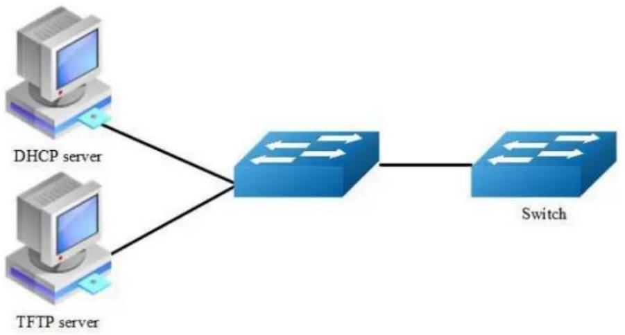
Figure 8-8 smart config
This figure is the network topology of testing SmartConfig function. We need two switches and two linux boxes to construct the test bed. "switch" in the figure is the switch we enable SmartCofng on. Note that the address of TFTP server provided by DHCP server can be used by switch to connect to TFTP server directly or via routes.
Enable smartConfig
step 1 Enter the configure mode
Switch#configure terminal
step 2 Enable smartConfigure
Switch(config)#smart-config initial-switch-deployment
step 3 Exit the configure mode
Switch (config)#exit
step 4 Validation
Use this command to check the smart-config settings:
Switch# show smart-config config
Smart-Config config:
initial-switch-deployment: on
hostname-prefix: on
Send log message to console: on
Using smartConfig
SmartConfig was enable default, so we just make sure there is no startup-config.conf file. Then switch will start SmartConfig next boot. And we can delete startup-config.conf manually, so that Smartconfig will work after reboot. Procedure of configure SmartConfig as fallow:
step 1:
Configure smartdeploy.xml file, and place it with image file, configuration file to tftp server. The directory must be like this (Configuration files should be in conf directory and images should be in images directory.) :
smartconfig/
| --conf/
| --images/
| --smartdeploy.xml
step 2:
Configure DHCP server, tftp server address option must be set;
step 3:
Make sure there is no startup-config.conf file;
step 4:
boot or reboot the system.
8.6.3 Application cases
N/A
8.7 Reboot Logs
8.7.1 Overview
Function Introduction
Switch support display reboot logs. Depend on these logs, user can judge the reboot reasons of a switch. The reboot reasons include Manual Reboot, Power Off or Other Reasons. Also, user can clear the reboot logs through a command.

User can find no more than ten reboot logs through this command, to find more reboot logs, can refer to the following file: flash:/reboot-info/reboot_info.log
Detail about the show result as following:
| Reboot Type | Description |
| POWER | Power outages |
| MANUAL | Cli “reboot/reload” is used |
| HIGH-TMPR | Reboot for abnormal high temperature |
| BHMDOG BHM | watchdog, monitor functional module |
| LCMDOG LCM | watchdog, monitor each LC |
| SCHEDULE | Schedule reboot |
| SNMP-RELOAD | SNMP reboot |
| HALFAIL | Reboot for HAGT communicate with HSRV failed, need stack enable |
| ABNORMAL | Unusual reboot, include reboot under shell |
| CTCINTR | Button reboot |
| LCATTACH | Reboot for LC attach CHSM failed |
| OTHER | Other reboot |
Principle Description
N/A
8.7.2 Configuration
Reboot logs are enabled by default. User can display and clear the logs as the following examples:
step 1 Display the logs
| Switch# show reboot-info | ||
| Times | Reboot Type | Reboot Time (DST) |
| 1 | MANUAL | 2000/01/01 01:21:35 |
| 2 | MANUAL | 2000/01/01 02:07:52 |
| 3 | MANUAL | 2000/01/01 02:24:59 |
| 4 | MANUAL | 2000/01/01 03:28:58 |
| 5 | MANUAL | 2000/01/01 03:43:02 |
| 6 | MANUAL | 2000/01/01 03:49:51 |
| 7 | MANUAL | 2000/01/01 04:01:23 |
| 8 | MANUAL | 2000/01/01 04:42:40 |
| 9 | MANUAL | 2000/01/01 04:49:27 |
| 10 | MANUAL | 2000/01/01 20:59:20 |
step 2 Clear the logs(optional)
Switch(config)# reset reboot-info
8.7.3 Application cases
N/A
9
Network Management Configuration Guide
9.1 Configuring Network Diagnosis
9.1.1 Overview
Function Introduction
Ping is a computer network administration utility used to test the reachability of a host on an Internet Protocol (IP) network and to measure the round-trip time for messages sent from the originating host to a destination computer. The name comes from active sonar terminology.
Ping operates by sending Internet Control Message Protocol (ICMP) echo request packets to the target host and waiting for an ICMP response. In the process it measures the time from transmission to reception (round-trip time) [1] and records any packet loss. The results of the test are printed in form of a statistical summary of the response packets received, including the minimum, maximum, and the mean round-trip times, and sometimes the standard deviation of the mean.
Traceroute is a computer network tool for measuring the route path and transit times of packets across an Internet Protocol (IP) network.
Traceroute sends a sequence of Internet Control Message Protocol (ICMP) packets addressed to a destination host. Tracing the intermediate routers traversed involves control of the time-to-live (TTL) Internet Protocol parameter. Routers decrement this parameter and discard a packet when the TTL value has reached zero, returning an ICMP error message (ICMP Time Exceeded) to the sender.
Principle Description
N/A
9.1.2 Configuration
Ping IP with in-band port
Switch# ping 10.10.29.247
Switch# ping ipv6 2001:1000::1
Ping IP with management port
Switch# ping mgmt-if 10.10.29.247
Switch# ping mgmt-if ipv6 2001:1000::1
Ping IP with VRF instance
Switch# ping vrf vrf1 10.10.10.1
Traceroute IP with inner port
Switch# traceroute 1.1.1.2
Switch# traceroute ipv6 2001:1000::1
9.1.3 Application cases
Example for Ping
Switch # ping mgmt-if 192.168.100.101
PING 192.168.100.101 (192.168.100.101) 56(84) bytes of data.
64 bytes from 192.168.100.101: icmp_seq=0 ttl=64 time=0.092 ms
64 bytes from 192.168.100.101: icmp_seq=1 ttl=64 time=0.081 ms
64 bytes from 192.168.100.101: icmp_seq=2 ttl=64 time=0.693 ms
64 bytes from 192.168.100.101: icmp_seq=3 ttl=64 time=0.071 ms
64 bytes from 192.168.100.101: icmp_seq=4 ttl=64 time=1.10 ms
--- 192.168.100.101 ping statistics ---
5 packets transmitted, 5 received, 0% packet loss, time 4054ms
rtt min/avg/max/mdev = 0.071/0.408/1.104/0.421 ms, pipe 2
Example for traceroute
Switch# traceroute 1.1.1.2
traceroute to 1.1.1.2 (1.1.1.2), 30 hops max, 38 byte packets
1 1.1.1.2 (1.1.1.2) 112.465 ms 102.257 ms 131.948 ms
Switch # ping mgmt-if ipv6 2001:1000::1
PING 2001:1000::1(2001:1000::1) 56 data bytes
64 bytes from 2001:1000::1: icmp_seq=1 ttl=64 time=0.291 ms
64 bytes from 2001:1000::1: icmp_seq=2 ttl=64 time=0.262 ms
64 bytes from 2001:1000::1: icmp_seq=3 ttl=64 time=0.264 ms
64 bytes from 2001:1000::1: icmp_seq=4 ttl=64 time=0.270 ms
64 bytes from 2001:1000::1: icmp_seq=5 ttl=64 time=0.274 ms
--- 2001:1000::1 ping statistics ---
5 packets transmitted, 5 received, 0% packet loss, time 3997ms rtt min/avg/max/mdev = 0.262/0.272/0.291/0.014 ms
9.2 Configuring NTP
9.2.1 Overview
Function Introduction
NTP is a tiered time distribution system with redundancy capability. NTP measures delays within the network and within the algorithms on the machine on which it is running. Using these tools and techniques, it is able to synchronize clocks to within milliseconds of each other when connected on a Local Area Network and within hundreds of milliseconds of each other when connected to a Wide Area Network. The tiered nature of the NTP time distribution tree enables a user to choose the accuracy needed by selecting a level (stratum) within the tree for machine placement. A time server placed higher in the tree (lower stratum number), provides a higher likelihood of agreement with the UTC time standard.
Some of the hosts act as time servers, that is, they provide what they believe is the correct time to other hosts. Other hosts act as clients, that is, they find out what time it is by querying a time server. Some hosts act as both clients and time servers, because these hosts are links in a chain over which the correct time is forwarded from one host to the next. As part of this chain, a host acts first as a client to get the correct time from another host that is a time server. It then turns around and functions as a time server when other hosts, acting as clients, send requests to it for the correct time.
Principle Description
N/A
9.2.2 Configuration
Configuring Client/Server mode connecting with in-band interface
Before configuring NTP client, make sure that NTP service is enabled on Server.
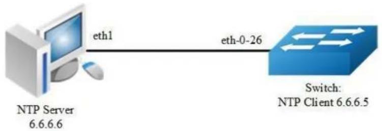
flowchart
graph LR
A["NTP Server 6.6.6.6"] -->|eth1| B["Switch: NTP Client 6.6.6.5"]
B -->|eth-0-26| A
Figure 9-1 NTP
step 1 Enter the configure mode
Switch#configure terminal
step 2 Enter the vlan configure mode and create a vlan
Switch(config)# vlan database
Switch(config-vlan)# vlan 10
Switch(config-vlan)# exit
step 3 Enter the interface configure mode and join the vlan
Switch(config)# interface eth-0-26
Switch(config-if)# switch access vlan 10
Switch(config-if)# no shutdown
Switch(config-if)# exit
step 4 create a vlan interface and set the IP address
Switch(config)# interface vlan10
Switch(config-if)# ip address 6.6.6.5/24
Switch(config-if)# exit
step 5 Set the attributes of NTP client
Enable a trustedkey; Configure the IP address of the NTP server; Enable authentication; Once you have enabled authentication, the client switch sends the time-of-day requests to the trusted NTP servers only; Configure ntp ace.
Switch(config)# ntp key 1 serverkey
Switch(config)# ntp server 6.6.6.6 key 1
Switch(config)# ntp authentication enable
Switch(config)# ntp trustedkey 1
Switch(config)# ntp ace 6.6.6.6 none
step 6 Exit the configure mode
Switch(config)# end
step 7 Validation
Switch# show ntp
Current NTP configuration:
----
NTP access control list:
6.6.6.6 mask 255.255.255.255 none
Unicast peer:
Unicast server:
6.6.6.6 key 1
Authentication: enabled
Local reference clock:
Disable management interface
Switch# show ntp status
Current NTP status:
----
clock is synchronized
stratum: 7
reference clock: 6.6.6.6
frequency: 17.365 ppm
precision: 2**20
reference time: d14797dd.70b196a2 (1:54:37.440 UTC Thu Apr 7 2011)
root delay: 0.787 ms
root dispersion: 23.993 ms
peer dispersion: 57.717 ms
clock offset: -0.231 ms
stability: 6.222 ppm
Switch# show ntp associations
Current NTP associations:
remote refid st when poll reach delay offset disp
*6.6.6.6 127.127.1.0 6 50 128 37 0.778 -0.234 71.945
synchronized, + candidate, # selected, x falsetick, . excess, - outlier
Configuring Client/Server mode connecting with management interface
step 1 Enter the configure mode
Switch# configure terminal
step 2 Enable ntp management interface
Switch(config)# ntp mgmt-if only
Note1: Use the following command to enable both in-band and management interface
Switch(config)# ntp mgmt-if enable
Note: Use the following command to disable management interface
Switch(config)# no ntp mgmt-if
step 3 Set the attributes of NTP client
Switch(config)# ntp key 1 serverkey
Switch(config)# ntp server 192.168.100.101 key 1
Switch(config)# ntp authentication enable
Switch(config)# ntp trustedkey 1
Switch(config)# ntp ace 192.168.100.101 none
step 4 Exit the configure mode
Switch(config)# end
step 5 Validation
Switch# show ntp
Current NTP configuration:
====================
NTP access control list:
192.168.100.101 mask 255.255.255.255 none
Unicast peer:
Unicast server:
192.168.100.101 key 1
Authentication: enabled
Local reference clock:
Only management interface
Switch# show ntp associations
Current NTP associations:
remote refid st when poll reach delay offset disp
====================
*192.168.100.101 127.127.1.0 3 27 64 1 1.328 2.033 433.075
* sys.peer, + candidate, # selected, x falsetick, . excess, - outlyer
9.2.3 Application cases
Configuring NTP Server (Use the ntpd of linux system for example)
Step 1 Display eth1 ip address
[root@localhost octeon]# ifconfig eth1
eth1 Link encap:Ethernet HWaddr 00:08:C7:89:4B:AA
inet addr:6.6.6.6 Bcast:6.6.6.255 Mask:255.255.255.0
inet6 addr: fe80::208:c7ff:fe89:4baa/64 Scope:Link
UP BROADCAST RUNNING MULTICAST MTU:1500 Metric:1
RX packets:3453 errors:1 dropped:0 overruns:0 frame:1
TX packets:3459 errors:0 dropped:0 overruns:0 carrier:0
collisions:0 txqueuelen:1000
RX bytes:368070 (359.4 KiB) TX bytes:318042 (310.5 KiB)
Step 2 Check networks via Ping
[root@localhost octeon]# ping 6.6.6.5
PING 6.6.6.5 (6.6.6.5) 56(84) bytes of data.
64 bytes from 6.6.6.5: icmp_seq=0 ttl=64 time=0.951 ms
64 bytes from 6.6.6.5: icmp_seq=1 ttl=64 time=0.811 ms
64 bytes from 6.6.6.5: icmp_seq=2 ttl=64 time=0.790 ms
Step 3 Configure ntp.conf
[root@localhost octeon]# vi /etc/ntp.conf
server 127.127.1.0 # local clock
fudge 127.127.1.0 stratum 5
#
<h1 id="drift-file-put-this-in-a-directory-which-the-daemon-can-write-to">Drift file. Put this in a directory which the daemon can write to.</h1>
<h1 id="no-symbolic-links-allowed-either-since-the-daemon-updates-the-file">No symbolic links allowed, either, since the daemon updates the file</h1>
<h1 id="by-creating-a-temporary-in-the-same-directory-and-then-rename-ing">by creating a temporary in the same directory and then rename() 'ing</h1>
<h1 id="it-to-the-file">it to the file.</h1>
#
driftfile /var/lib/ntp/drift
broadcastdelay 0.008
broadcast 6.6.6.255
#
<h1 id="please-do-not-use-the-default-values-here-pick-your-own-or-remote">PLEASE DO NOT USE THE DEFAULT VALUES HERE. Pick your own, or remote</h1>
<h1 id="systems-might-be-able-to-reset-your-clock-at-will-note-also-that">systems might be able to reset your clock at will. Note also that</h1>
<h1 id="ntpd-is-started-with-a-a-flag-disabling-authentication-that">ntpd is started with a -A flag, disabling authentication, that</h1>
<h1 id="will-have-to-be-removed-as-well">will have to be removed as well.</h1>
#
<h1 id="disable-auth">disable auth</h1>
keys /etc/ntp/keys
trustedkey 1
Step 4 Configure keys
[root@localhost octeon]# vi /etc/ntp/keys
#
<h1 id="please-do-not-use-the-default-values-here-pick-your-own-or-remote-2">PLEASE DO NOT USE THE DEFAULT VALUES HERE. Pick your own, or remote</h1>
<h1 id="systems-might-be-able-to-reset-your-clock-at-will-note-also-that-2">systems might be able to reset your clock at will. Note also that</h1>
<h1 id="ntpd-is-started-with-a-a-flag-disabling-authentication-that-2">ntpd is started with a -A flag, disabling authentication, that</h1>
<h1 id="will-have-to-be-removed-as-well-2">will have to be removed as well.</h1>
#
1 M serverkey
Step 5 Start ntpd service
[root@localhost octeon]# ntpd
9.3 Configuring Phy Loopback
9.3.1 Overview
Function Introduction
Phy loopback is a proprietary based loopback. There are 2 types of phy loopback: phy(including internal and external) level loopback and port level loopback.
If a physical port is configured as “external phy loopback”, all packets coming into this port should be loopback back from the port itself at phy level.
If a physical port is configured as “internal phy loopback”, all packets expected out from this port should be looped back to specified physical port.
If a physical port is configured as “port loopback”, all packets coming into this port should be looped back from the port itself, and whether to swap the SMAC with the DMAC should be selectable by users. And if the MAC is swapped, the CRC should be recalculated.
Principle Description
N/A
9.3.2 Configuration
Configuring external phy loopback

Figure 9-2 external phy topology
step 1 Enter the configure mode
Switch# configure terminal
step 2 Enter the interface configure mode and set loopback phy external
Switch (config)# interface eth-0-1
Switch (config-if)# no shutdown
Switch (config-if)# loopback phy external
step 3 Exit the configure mode
Switch (config-if)# end
step 4 Validation
Switch# show phy loopback
Interface Type DestIntf SwapMac
eth-0-1 external - -
Configuring internal phy loopback

flowchart
graph LR
A["loopback phy internal"] --> B["eth-0-1"]
B --> C["Destination port"]
D["eth-0-2"] --> E["Destination port"]
Figure 9-3 Internal phy topology
step 1 Enter the configure mode
Switch # configure terminal
step 2 Enter the interface configure mode and set loopback phy internal and specify the destination interface
Switch (config)# interface eth-0-2
Switch (config-if)# no shutdown
Switch (config-if)# exit
Switch (config)# interface eth-0-1
Switch (config-if)# no shutdown
Switch (config-if)# loopback phy internal eth-0-2
step 3 Exit the configure mode
Switch (config-if)# end
step 4 Validation
Switch# show phy loopback
Interface Type DestIntf SwapMac
eth-0-1 internal eth-0-2 -
Configuring port level loopback
eth-0-1
loopback port mac-address swap

Figure 9-4 Port level topology
step 1 Enter the configure mode
Switch # configure terminal
step 2 Enter the interface configure mode and set loopback phy mac-address swap
Switch (config)# interface eth-0-1
Switch (config-if)# no shutdown
Switch (config-if)# loopback port mac-address swap
step 3 Exit the configure mode
Switch (config-if)# end
step 4 Validation
Switch# show phy loopback
Interface Type DestIntf SwapMac
eth-0-1 port - yes
9.3.3 Application cases
N/A
9.4 Configuring L2 ping
9.4.1 Overview
Function Introduction
The tool L2 ping is a useful application which's purpose is detecting the connection between two switches. The L2 ping tool is not same with the well-known 'ping IP-ADDRESS' in the WINDOWS system. The normal "ping" is realized by the protocol ICMP which is dependent on the IP layer, so it may be inapplicable if the destination device is only Layer 2 switch. But the protocol used by L2 ping is only relying on Layer 2 ethernet packets.
When L2 ping is started, the L2 ping protocol packet (with ether type '36873(0x9009)') is sent from a specified physical port to another specified destination port. At the destination end, the L2 ping protocol will be sent back via non 802.1ag loopback, or via a configuration "l2 ping response". The device which is pinging, will receive the ping response packet, and print the ping result.
Principle Description
N/A
9.4.2 Configuration

flowchart
graph LR
A["Switch1"] -->|eth-0-1| B["Switch2"]
B -->|L2 ping| A
A -.->|L2 ping response| B
Figure 9-5 ping a switch port
The configurations are almost same on Switch1 and Switch2, except the parts which are specially pointed out.
step 1 Enter the configure mode
Switch# configure terminal
step 2 Enter the interface configure mode and turn up the interface
Switch (config)# interface eth-0-1
Switch (config-if)# no shutdown
step 3 Enable the L2 ping response function
Configure on Switch2:
Switch (config-if)# 12 ping response enable
step 4 Exit the configure mode
Switch (config-if)# end
step 5 Using L2 ping
Operate on Switch1:
Switch1# 12 ping 001e.0808.58f1 interface eth-0-1 count 10 interval 1000 timeout 2000
Sending 10 L2 ping message(s):
64 bytes from 001e.0808.58f1: sequence = 0, time = 10ms
64 bytes from 001e.0808.58f1: sequence = 1, time = 15ms
64 bytes from 001e.0808.58f1: sequence = 2, time = 13ms
64 bytes from 001e.0808.58f1: sequence = 3, time = 12ms
64 bytes from 001e.0808.58f1: sequence = 4, time = 20ms
64 bytes from 001e.0808.58f1: sequence = 5, time = 21ms
64 bytes from 001e.0808.58f1: sequence = 6, time = 12ms
64 bytes from 001e.0808.58f1: sequence = 7, time = 16ms
64 bytes from 001e.0808.58f1: sequence = 8, time = 14ms
64 bytes from 001e.0808.58f1: sequence = 9, time = 17ms
L2 ping completed.
10 packet(s) transmitted, 10 received, 0 % packet loss
001e.0808.58f1 is the MAC address of the interface on Switch2. It can be gained by command "show interface eth-0-1" on Switch2.
9.4.3 Application cases
N/A
9.5 Configuring RMON
9.5.1 Overview
Function Introduction
RMON is an Internet Engineering Task Force (IETF) standard monitoring specification that allows various network agents and console systems to exchange network monitoring data. You can use the RMON feature with the Simple Network Management Protocol (SNMP) agent in the switch to monitor all the traffic flowing among switched on all connected LAN segments.
RMON is a standard monitoring specification that defines a set of statistics and functions that can be exchanged between RMON-compliant console systems and network probes RMON provides you with comprehensive network-fault diagnosis, planning, and performance-tuning information.
Principle Description
N/A
9.5.2 Configuration
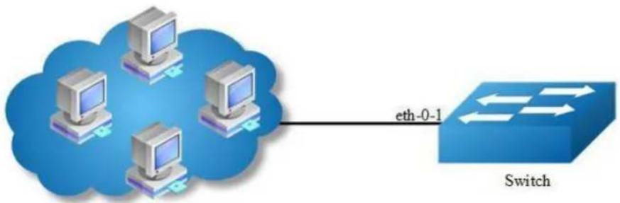
flowchart
graph LR
A["Computer 1"] -->|eth-0-1| B["Switch"]
C["Computer 2"] -->|eth-0-1| B["Switch"]
D["Computer 3"] -->|eth-0-1| B["Switch"]
E["Computer 4"] -->|eth-0-1| B["Switch"]
Figure 9-6 rmon
step 1 Enter the configure mode
Switch# configure terminal
step 2 Enter the interface configure mode and create a stats and a history
Switch(config)# interface eth-0-1
Switch(config-if)# rmon collection stats 1 owner test
Switch(config-if)# rmon collection history 1 buckets 100 interval 1000 owner test
Switch(config-if)# exit
step 3 Create an event with log and trap both set.
Switch(config)# rmon event 1 log trap public description test_event owner test
step 4 Create a alarm using event 1 we created before and monitor the alarm on ETHERSTATSBROADCASTPKTS on eth-0-1
Switch(config)# rmon alarm 1 etherStatsEntry.6.1 interval 1000 delta rising-threshold 1000 event 1 falling-threshold 1 event 1 owner test
step 5 Exit the configure mode
Switch(config)# end
step 6 Validation
Switch# show rmon statistics
Rmon collection index 1
Statistics ifindex = 1, Owner: test
Input packets 0, octets 0, dropped 0
Broadcast packets 0, multicast packets 0, CRC alignment errors 0, collisions 0
Undersized packets 0, oversized packets 0, fragments 0, jabbers 0
# of packets received of length (in octets):
64: 0, 65-127: 0, 128-255: 0
256-511: 0, 512-1023: 0, 1024-max: 0
Switch# show rmon history
History index = 1
Data source ifindex = 1
Buckets requested = 100
Buckets granted = 100
Interval = 1000
Owner: test
Switch# show rmon event
Event Index = 1
Description: test_event
Event type Log & Trap
Event community name: public
Last Time Sent = 00:00:00
Owner: test
Switch# show rmon alarm
Alarm Index = 1
Alarm status = VALID
Alarm Interval = 1000
Alarm Type is Delta
Alarm Value = 00
Alarm Rising Threshold = 1000
Alarm Rising Event = 1
Alarm Falling Threshold = 1
Alarm Falling Event = 1
Alarm Owner is test
9.5.3 Application cases
N/A
9.6 Configuring SNMP
9.6.1 Overview
Function Introduction
SNMP is an application-layer protocol that provides a message format for communication between managers and agents. The SNMP system consists of an SNMP manager, an SNMP agent, and a MIB. The SNMP manager can be part of a network management system (NMS). The agent and MIB reside on the switch. To configure SNMP on the switch, you define the relationship between the manager and the agent. The SNMP agent contains MIB variables whose values the SNMP manager can request or change. A manager can get a value from an agent or store a value into the agent. The agent gathers data from the MIB, the repository for information about device parameters and network data. The agent can also respond to a manager's requests to get or set data. An agent can send unsolicited traps to the manager. Traps are messages alerting the SNMP manager to a condition on the network. Error user authentication, restarts, link status (up or down), MAC address tracking, closing of a Transmission Control Protocol (TCP) connection, loss of connection to a neighbor, or other significant events may send a trap.
Principle Description
SNMP module is based on the following RFC draft:
SNMPv1: Defined in RFC 1157.
SNMPv2C: Defined in RFC 1901.
SNMPv3: Defined in RFC 2273 to 2275.
Following is a brief description of terms and concepts used to describe the SNMP protocol:
Agent: A network-management software module, an agent has local knowledge of management information and translates that information into a form compatible with SNMP.
Management Information Base (MIB): Management Information Base, collection of information is organized hierarchically.
Engine ID: A unique ID for a network's node.
Trap: Used by managed devices to asynchronously report events to the NMS.
9.6.2 Configuration
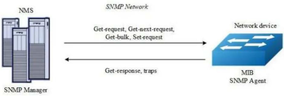
flowchart
graph LR
A["NMS"] -->|Get-request, Get-next-request, Get-bulk, Set-request| B["Network device"]
C["SNMP Manager"] -->|Get-response, traps| B
B --> D["MIB SNMP Agent"]
style A fill:#f9f,stroke:#333
style C fill:#f9f,stroke:#333
style B fill:#ccf,stroke:#333
style D fill:#cff,stroke:#333
Figure 9-7 snmp
As shown in the figure SNMP agent gathers data from the MIB. The agent can send traps, or notification of certain events, to the SNMP manager, which receives and processes the traps. Traps alert the SNMP manager to a condition on the network such as improper user authentication, restarts, link status (up or down), MAC address tracking, and so forth. The SNMP agent also responds to MIB-related queries sent by the SNMP manager in get-request, get-next-request, and set- request format.
Enable SNMP
step 1 Enter the configure mode
Switch# configure terminal
step 2 Enable SNMP globally
Switch(config)# snmp-server enable
step 3 Exit the configure mode
Switch(config)# end
step 4 Validation
Switch# show running-config snmp-server enable
Configuring community string
You use the SNMP community string to define the relationship between the SNMP manager and the agent. The community string acts like a password to permit access to the agent on the switch. Optionally, you can specify one or more of these characteristics associated with the string:
A MIB view, which defines the subset of all MIB objects accessible to the given community
Read and write or read-only permission for the MIB objects accessible to the community
Beginning in privileged EXEC mode, follow these steps to configure a community string on the switch.
step 1 Enter the configure mode
Switch# configure terminal
step 2 Configuring community string
Configure a view named "DUT"(optional); Configure a community named "public" with read access and view "DUT".
Switch(config)# snmp-server view DUT included 1
Switch(config)# snmp-server community public read-write (view DUT)
step 3 Exit the configure mode
Switch(config)# end
step 4 Validation
Switch# show running-config
snmp-server enable
snmp-server view DUT included .1
snmp-server community public read-only view DUT
Configuring SNMPv3 Groups, Users and Accesses
You can specify an identification name (engine ID) for the local SNMP server engine on the switch. You can configure an SNMP server group that maps SNMP users to SNMP views, you can add new users to the SNMP group, and you can add access for the SNMP group.
Beginning in privileged EXEC mode, follow these steps to configure SNMP on the switch.
step 1 Enter the configure mode
Switch# configure terminal
step 2 Set the globle configurations for SNMP
Set engineID; Set the user name, password, and authentication type; Create SNMP server; Set the authority for the group member.
Switch(config)# snmp-server engineID 8000123456
Switch(config)# snmp-server usm-user usr1 authentication md5 mypassword privacy des yourpassword
Switch(config)# snmp-server group grp1 user usr1 security-model usm
Switch(config)# snmp-server access grp1 security-model usm noauth
step 3 Exit the configure mode
Switch(config)# end
step 4 Validation
Switch# show running-config
snmp-server engineID 8000123456
snmp-server usm-user usr1 authentication md5 mypassword privacy des yourpassword
snmp-server group grpl user usr1 security-model usm
snmp-server access grpl security-model usm noauth
SNMPv1 and SNMPv2 notifications configure
Beginning in privileged EXEC mode, follow these steps to configure SNMP on the switch.
step 1 Enter the configure mode
Switch# configure terminal
step 2 Set the global configurations for SNMP
Enable all supported traps; Configure a remote trap manager which IP is "10.0.0.2"; Configure a remote trap manager which IPv6 address is "2001:1000::1".
Switch(config)# snmp-server trap enable all
Switch(config)# snmp-server trap target-address 10.0.0.2 community public
Switch(config)# snmp-server trap target-address 2001:1000::1 community public
step 3 Exit the configure mode
Switch(config)# end
step 4 Validation
Switch# show running-config
snmp-server trap target-address 10.0.0.2 community public
snmp-server trap target-address 2001:1000::1 community public
snmp-server trap enable vrrp
snmp-server trap enable igmp snooping
snmp-server trap enable ospf
snmp-server trap enable pim
snmp-server trap enable stp
snmp-server trap enable system
snmp-server trap enable coldstart
snmp-server trap enable warmstart
snmp-server trap enable linkdown
snmp-server trap enable linkup
Configuring SNMPv3 notifications
step 1 Enter the configure mode
Switch# configure terminal
step 2 Set the global configurations for SNMP
Enable all supported traps; Configure a trap notify item for SNMPv3; Configure a remote trap manager's IP address; Configure a remote trap manager's IPv6 address; Add a local user to SNMPv3 notifications.
Switch(config)# snmp-server trap enable all
Switch(config)# snmp-server notify notif1 tag tmptag trap
Switch(config)# snmp-server target-address targ1 param parml 10.0.0.2 taglist tmptag
Switch(config)# snmp-server target-address t1 param p1 2001:1000::1 taglist tag1
Switch(config)# snmp-server target-params parml user usr1 security-model v3 message-processing v3 noauth
step 3 Exit the configure mode
Switch(config)# end
step 4 Validation
Switch# show running-config
snmp-server notify notif1 tag tmptag trap
snmp-server target-address tl param pl 2001:1000::1 taglist tagl
snmp-server target-address targ1 param parm1 10.0.0.2 taglist tmptag
snmp-server target-params parml user usr1 security-model v3 message-processing v3
noauth
snmp-server trap enable vrrp
snmp-server trap enable igmp snooping
snmp-server trap enable ospf
snmp-server trap enable pim
snmp-server trap enable stp
snmp-server trap enable system
snmp-server trap enable coldstart
snmp-server trap enable warmstart
snmp-server trap enable linkdown
snmp-server trap enable linkup
9.6.3 Application cases
N/A
9.7 Configuring SFLOW
9.7.1 Overview
Function Introduction
sFlow is a technology for monitoring traffic in data networks containing switches and routers. In particular, it defines the sampling mechanisms implemented in a sFlow Agent for monitoring traffic, and the format of sample data used by the sFlow Agent when forwarding data to a central data collector.
The architecture and sampling techniques used in the sFlow monitoring system are designed to provide continuous site-wide (and network-wide) traffic monitoring for high speed switched and routed networks.
The sFlow Agent uses two forms of sampling: statistical packet-based sampling of switched flows, and time-based sampling of network interface statistics.
Default Configuration for sflow:
| Feature | Default Setting |
| global sflow | disabled |
| sflow on port | disable |
| collector udp port | 6343 |
| counter interval time | 20 seconds |
Principle Description
N/A
9.7.2 Configuration
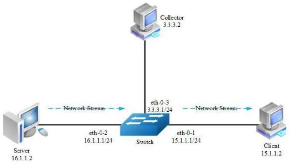
flowchart
graph TD
Server["Server 16.1.1.2"] -->|eth-0-2 16.1.1.1/24| Switch["Switch"]
Switch -->|eth-0-3 3.3.3.1/24| Collector["Collector 3.3.3.2"]
Switch -->|eth-0-1 15.1.1.1/24| Client["Client 15.1.1.2"]
Switch -->|Network Stream| Server
Switch -->|Network Stream| Client
Figure 9-8 sflow
step 1 Enter the configure mode
Switch# configure terminal
step 2 Enable sflow globally
Switch(config)# sflow enable
step 3 Set the global attribute for sflow
Set the agent IP address, set the collector IP address and udp port. If the udp port is not specified, it means default port 6364.
Switch(config)# sflow agent ip 3.3.3.1 Switch(config)# sflow collector 3.3.3.2 6342
Set the agent and collector with IPv6:
Switch(config)# sflow agent ipv6 2001:2000::2 Switch(config)# sflow collector 2001:2000::1

NOTE
At list one Agent and one collector must be configured for sflow.
User can use IPv4 or IPv6.
Set the interval to send interface counter information (optional):
Switch(config)# sflow counter interval 15
step 4 Enter the interface configure mode and set the attributes of the interfaces
Switch(config)# interface eth-0-1
Switch(config-if)# no switchport
Switch(config-if)# no shutdown
Switch(config-if)# ip address 15.1.1.1/24
Switch(config-if)# exit
Switch(config)# interface eth-0-2
Switch(config-if)# no switchport
Switch(config-if)# no shutdown
Switch(config-if)# ip address 16.1.1.1/24
Switch(config-if)# exit
Switch(config)# interface eth-0-3
Switch(config-if)# no switchport
Switch(config-if)# no shutdown
Switch(config-if)# ip address 3.3.3.1/24
Switch(config-if)# exit
step 5 Enable sflow for input packets on eth-0-1
Switch(config)# interface eth-0-1
Switch(config-if)# sflow flow-sampling rate 8192
Switch(config-if)# sflow flow-sampling enable input
Switch(config-if)# sflow counter-sampling enable
Switch(config-if)# exit
step 6 Validation
To display the sflow configuration, use following command:
Switch# show sflow
sFlow Version: 5
sFlow Global Information:
Agent IPv4 address : 3.3.3.1
Agent IPv6 address : 2001:1000::2
Counter Sampling Interval : 15 seconds
Collector 1:
IPv4 Address: 3.3.3.2
vrf: N/A
Port: 6342
Collector 2:
IPv6 Address: 2001:1000::1
vrf: N/A
Port: 6343
sFlow Port Information:
Port Counter Flow Flow-Sample Flow-Sample Direction Rate
eth-0-1 Enable Enable Input 8192
9.7.3 Application cases
N/A
9.8 Configuring LLDP
9.8.1 Overview
Function Introduction
LLDP ( Link Layer Discovery Protocol ) is the discovery protocol on link layer defined as standard in IEEE 802.1ab. Discovery on Layer 2 can locate interfaces attached to the devices exactly with connection information on layer 2, such as VLAN attribute of port and protocols supported, and present paths among client, switch, router, application servers and other network servers. This detailed description is helpful to get useful information for diagnosing network fast, like topology of devices attached, conflict configuration between devices, and reason of network failure.
Principle Description
N/A
9.8.2 Configuration

flowchart
graph LR
A["Switch1"] -->|eth-0-9| B["Switch2"]
B -->|eth-0-9| A
Figure 9-9 lldp
step 1 Enter the configure mode
Switch# configure terminal
step 2 Enable SNMP globally
Switch(config)# lldp enable
step 3 Enter the interface configure mode and set the attributes of LLDP on the interface
Switch(config)# interface eth-0-9
Switch(config)# no shutdown
Switch(config-if)# no lldp tlv 8021-org-specific vlan-name
Switch(config-if)# lldp tlv med location-id ccs-elin 1234567890
Switch(config-if)# lldp enable txrx
Switch(config-if)# exit
step 4 Set LLDP timers (optional)
Configure the transmitting interval of LLDP packet to 40 seconds; Configure the transmitting delay of LLDP packet to 3 seconds; Configure the reinit delay of LLDP function to 1 second.
Switch(config)# lldp timer mag-tx-interval 40
Switch(config)# lldp timer tx-delay 3
Switch(config)# lldp timer reinitDelay 1
step 5 Exit the configure mode
Switch(config)# end
step 6 Validation
To display the LLDP configuration, use following command:
Switch# show lldp local config
LLDP global configuration:
LLDP function global enabled : YES
LLDP msgTxHold : 4
LLDP msgTxInterval : 40
LLDP reinitDelay : 1
LLDP txDelay : 3
Switch# show lldp local config interface eth-0-9
LLDP configuration on interface eth-0-9 :
LLDP admin status : TXRX
Basic optional TLV Enabled:
Port Description TLV
System Name TLV
System Description TLV
System Capabilities TLV
Management Address TLV
IEEE 802.1 TLV Enabled:
Port Vlan ID TLV
Port and Protocol Vlan ID TLV
Protocol Identity TLV
IEEE 802.3 TLV Enabled:
MAC/PHY Configuration/Status TLV
Power Via MDI TLV
Link Aggregation TLV
Maximum Frame Size TLV
LLDP-MED TLV Enabled:
Med Capabilities TLV
Network Policy TLV
Location Identification TLV
Extended Power-via-MDI TLV
Inventory TLV
Switch# show running-config
!
lldp enable
lldp timer msg-tx-interval 40
lldp timer reinit-delay 1
lldp timer tx-delay 3
!
interface eth-0-9
lldp enable txrx
no lldp tlv 8021-org-specific vlan-name
lldp tlv med location-id ecs-elin 1234567890
!
Switch# show lldp neighbor
Local Port eth-0-1 has 0 neighbor(s)
Local Port eth-0-2 has 0 neighbor(s)
...
Local Port eth-0-9 has 2 neighbor(s)
Remote LLDP Information of port eth-0-9
Neighbor Index : 1
Chassis ID type: Mac address
Chassis ID : 48:16:be:a4:d7:09
Port ID type : Interface Name
Port ID : eth-0-9
TTL : 160
Expired time: 134
...
Location Identification :
ECS ELIN: 1234567890
9.9 Configuring IPFIX
9.9.1 Overview
Function Introduction
Traffic on a data network can be seen as consisting of flows passing through network elements. For administrative or other purposes, it is often interesting, useful, or even necessary to have access to information about these flows that pass through the network elements. This requires uniformity in the method of representing the flow information and the means of communicating the flows from the network elements to the collection point. This is what IPFIX can do.
Before IPFIX was introduced, there is a Cisco private method NetFlow. IPFIX is similar to NetFlow and is based on NetFlow version 9.
Principle Description
N/A
9.9.2 Configuration
step 1 Enter the configure mode
Switch# configure terminal
step 2 Set the aging time(optional)
Set the aging time as 300 seconds. The aging time is 1800 seconds by default.
Switch(config)# ipfix global
Switch(Config-ipfix-global)# flow aging 300
step 3 Configuring recorder
Switch(config)# ipfix recorder recorder1
Switch (Config-ipfix-reocrder)# match mac source address
Switch (Config-ipfix-reocrder)# match ipv4 source address mask 32
Switch (Config-ipfix-reocrder)# match ipv4 destination address mask 32
Switch (Config-ipfix-reocrder)# match vxlan-vni
Switch (Config-ipfix-reocrder)# collect counter bytes
Switch (Config-ipfix-reocrder)# collect counter packets
Switch (Config-ipfix-reocorder) # exit
step 4 Configuring sampler
Switch(config)# ipfix sampler sampler1
Switch (Config-ipfix-sampler) # 1 out-of 100
Switch (Config-ipfix- sampler) # exit
step 5 Configuring exporter
Switch(config)# ipfix exporter exporter1
Switch (Config-ipfix-exporter)# destination 10.10.10.1
Switch (Config-ipfix-exporter)# source interface eth-0-2
Switch (Config-ipfix-exporter)# flow data timeout 200
Switch (Config-ipfix-exporter)# event flow end timeout
Switch (Config-ipfix-exporter)# exit
step 6 Configuring monitor
Switch(config)# ipfix monitor monitor1
Switch (Config-ipfix-monitor) # recorder recorder1
Switch (Config-ipfix-monitor) # exporter exporter1
Switch (Config-ipfix-monitor) # exit
step 7 Enter the interface configure mode and apply ipfix
Switch(config)# interface eth-0-1
Switch(config-if)# ipfix monitor input monitor1 sampler sampler1
Switch(config-if)# exit
step 8 Exit the configure mode
Switch(config)# end
step 9 Validation
Use the following commands to validate the configuration:
Switch# show ipfix global
IPFIX global information:
Current flow cache number : 0(ingress: 0, egress: 0)
Flow cache aging interval : 300 seconds
Flow cache export interval : 5 seconds
Flow cache memory usage threshold : 90%
Flow cache sampler mode : all flow
Flow cache packet wraparound threshold : 67108863
Flow cache byte wraparound threshold : 4294967295
Flow cache dropped packet wraparound threshold : 1023
Flow cache jitter threshold : 65535
Flow cache latency threshold : 16777215
Switch# show ipfix recorder recorder1
IPFIX recorder information:
Name : recorder1
Description :
Match info :
match Source Mac Address
match IPv4 Source Address
match IPv4 Destination Address
match Vxlanvni
Collect info :
collect Flow Byte Number
collect Flow Packet Number
Switch# show ipfix exporter exporter1
IPFIX exporter information:
Name : exporter1
Description :
Exporter Interface : eth-0-2
Domain ID : 0
Collector Name : 10.10.10.1
IPFIX message protocol : UDP
IPFIX message destination Port : 2055
IPFIX message TTL value : 255
IPFIX message DSCP value : 63
IPFIX data interval : 200
IPFIX template interval : 1800
IPFIX exporter events :
Flow aging event
Switch# show ipfix sampler sampler1
IPFIX sampler information:
Name : sampler1
Description :
Rate : 100
Switch# show ipfix monitor monitor1
IPFIX monitor information:
Name : monitor1
Description :
Recorder : recorder1
exporter : exporter1
flow mirror packet : 0
flow mirror destination : NA
9.9.3 Application cases
N/A
10
Traffic Managemant Configuration Guide
10.1 Configuring QoS
10.1.1 Overview
Function Introduction
Quality of Service (QoS) can be used to give certain traffic priority over other traffic. Without QoS, all traffic in a network has the same priority and chance of being delivered on time. If congestion occurs, all traffic has the same chance of being dropped. With QoS, specific network traffic can be prioritized to receive preferential treatment. In turn, a network performs more predictably, and utilizes bandwidth more effectively.
Classification information can be carried in the Layer-3 IP packet header or the Layer-2 frame. IP packet headers carry the information using 6 bits or 3 bits from the deprecated IP type of service (TOS) field. Layer-2 802.1Q frames carry the information using a 2-byte Tag Control Information field.
All switches and routers accessing the Internet depend on class information to give the same forwarding treatment to packets with the same class information, and give different treatment to packets with different class information. A packet can be assigned class information, as follows:
End hosts or switches along a path, based on a configured policy
Detailed packet examination, expected to occur nearer to the network edge, to prevent overloading core switches and routers
A combination of the above two techniques
Class information can be used by switches and routers along a path to limit the amount of allotted resources per traffic class.
Per-hop behavior is an individual device's behavior when handling traffic in the DiffServ architecture. An end-to-end QoS solution can be created if all devices along a path have consistent per-hop behavior.
Principle Description
Following is a brief description of terms and concepts used to describe QoS:
ACL
Access control lists (ACLs) classify traffic with the same characteristics. IP traffic is classified using IP ACLs, and non-IP traffic is classified using MAC ACLs. The ACL can have multiple access control entries (ACEs), which are commands that match fields against the contents of the packet.
CoS Value
Class of Service (CoS) is a 3-bit value used to classify the priority of Layer-2 frames upon entry into a network.
QoS classifies frames by assigning priority-indexed CoS values to them, and gives preference to higher-priority traffic.
Layer-2 802.1Q frame headers have a 2-byte Tag Control Information field that carries the CoS values in the 3 most significant bits, called the User Priority bits. On interfaces configured as Layer-2 802.1Q trunks, all traffic is in 802.1Q frames, except for traffic in the native VLAN.
Other frame types cannot carry Layer-2 CoS values. CoS values range from 0 to 7.
DSCP Value
Differentiated Services Code Point (DSCP) is a 6-bit value used to classify the priority of Layer-3 packets upon entry into a network.
DSCP values range from 0 to 63.
IP-Precedence Value
IP-Precedence is a 3-bit value used to classify the priority of Layer-3 packets upon entry into a network.
IP-Precedence values range from 0 to 7.
EXP Value
EXP value is a 3-bit value used to classify the priority of MPLS packets upon entry into a network.
MPLS EXP values range from 0 to 7.
Classification
Classification distinguishes one kind of traffic from another by examining the fields in the packet. The process generates an internal priority for a packet, which identifies all future QoS actions to be taken on the packet.
Each packet is classified upon entry into the network. At the ingress, the packet is inspected, and the priority is determined based on ACLs or the configuration. The Layer-2 CoS value is then mapped to a priority value.
The classification is carried in the IP packet header using 6 bits or 3 bits from the deprecated IP TOS field to carry the classification information. Classification can also occur in the Layer-2 frame.
Classification occurs on an ingress physical port, but not at the switch virtual interface level.
Classification can be based on CoS/inner-CoS/DSCP/IP-Precedence, default port cos, or class maps and policy maps.
Shaping
Shaping is to change the rate of incoming traffic flow to regulate the rate in such a way that the outgoing traffic flow behaves more smoothly. If the incoming traffic is highly bursty, it needs to be buffered so that the output of the buffer is less bursty and smoother.
Shaping has the following attributes:
➢ Shaping can be deployed base on physical port.
Shaping can be deployed on queues of egress interface.
Policing
Policing determines whether a packet is in or out of profile by comparing the internal priority to the configured policer.
The policer limits the bandwidth consumed by a traffic flow. The result is given to the marker.
There are two types of policers:
Individual: QoS applies the bandwidth limits specified in the policer, separately, to each matched traffic class. An individual policer is configured within a policy map.
Aggregate: QoS applies the bandwidth limits specified in an aggregate policer, cumulatively, to all matched traffic flows. An aggregate policer is configured by specifying the policer name within a policy map. The bandwidth limits of the policer are specified. In this way, the aggregate policer is shared by multiple classes of traffic within one or multiple policy map.
Marking
Marking determines how to handle a packet when it is out of profile. It assesses the policer and the configuration information to determine the action required for the packet, and then handles the packet using one of the following methods:
➢ Let the packet through and mark color down
Drop the packet
Marking can occur on ingress and egress interfaces.
Queuing
Queuing maps packets to a queue. Each egress port can accommodate up to 8 unicast queues, 1 multicast queue and 1 SPAN queue.
The packet internal priority can be mapped to one of the egress queues. The unit of queue depth is buffer cell. Buffer cell is the granularity, which is 288 bytes, for packet storing.
After the packets are mapped to a queue, they are scheduled.
Tail Drop
Tail drop is the default congestion-avoidance technique on the interface. With tail drop, packets are queued until the thresholds are exceeded. The packets with different priority and color are assigned to different drop precedence. The mapping between priority and color to queue and drop precedence is configurable. You can modify the three tail-drop threshold to every egress queue by using the queue threshold interface configuration command. Each threshold value is packet buffer cell.
WRED
Weighted Random Early Detection (WRED) differs from other congestion-avoidance techniques because it attempts to anticipate and avoid congestion, rather than controlling congestion when it occurs.
WRED reduces the chances of tail drop by selectively dropping packets when the output interface begins to show signs of congestion. By dropping some packets early rather than waiting until the queue is full, WRED avoids dropping large numbers of packets at once. Thus, WRED allows the transmission line to be fully used at all times. WRED also drops more packets from large users than small. Therefore, sources that generate the most traffic are more likely to be slowed down versus sources that generate little traffic.
You can enable WRED and configure the two thresholds for a drop-precedence assigned to every egress queues. The WRED's color drop precedence map is the same as tail-drop's. Each min-threshold represents where WRED starts to randomly drop packets. After min-threshold is exceeded, WRED randomly begins to drop packets assigned to this threshold. As the queue max-threshold is approached, WRED continues to drop packets randomly with the rate of drop-probability. When the max-threshold is reached, WRED drops all packets assigned to the threshold. By default, WRED is disabled.
Scheduling
Scheduling forwards conditions packets using combination of WDRR and SP. Every queue belongs to a class. The class range from 0 to 7, and 7 is the highest priority. Several queues can be in a same class, or non queue in some class. Packets are scheduled by SP between classes and WDRR between queues in a class.
Strict Priority-Based (SP), in which any high-priority packets are first transmitted. Lower-priority packets are transmitted only when the higher-priority queues are empty. A problem may occur when too many lower-priority packets are not transmitted.
Weighted Deficit Round Robin (WDRR), in which each queue is assigned a weight to control the number of packets relatively sent from each queue.
Class Map
A class map names and isolates specific traffic from other traffic. The class map defines the criteria used to match against a specific traffic flow to further classify it. The criteria can match several access groups defined by the ACL.
If there is more than one type of traffic to be classified, another class map can be created under a different name. After a packet is matched against the class-map criteria, it is further classified using a policy map.
Policy Map
A policy map specifies on which traffic class to act. This can be implemented as follows:
Set a specific priority and color in the traffic class.
➢ Set a specific trust policy to map priority and color.
Specify the traffic bandwidth limitations for each matched traffic class (policer) and the action to take (marking) when the traffic is out of profile.
➢ Redirect the matched traffic class to a specific physical interface.
Mirror the matched traffic class to a specific monitor session, which's destination is defined in mirror module(please refer to the "monitor session destination" command).
Enable statistics of matching each ace or each class-map(if the class-map operator is match-any).
Policy maps have the following attributes:
A policy map can contain multiple class statements, each with different match criteria and action.
A separate policy-map class can exist for each type of traffic received through an interface.
There can be only one policy map per interface per direction. The same policy map can be applied to multiple interfaces and directions.
Before a policy map can be effective, it must be attached to an interface.
A policy map can be applied on physical interface(not link agg member), link agg interface, or vlan interface.
Mapping Tables
During QoS processing, the switch represents the priority of all traffic (including non-IP traffic) with an internal priority value:
During classification, QoS uses configurable mapping tables to derive the internal priority (a 6-bit value) from received CoS, EXP(3-bit), DSCP or IP precedence (3-bit) values. These maps include the CoS-to-priority-color/COS-to-PHB map, EXP-to-priority-color/EXP-to-PHB map, DSCP-to-priority-color/DSCP-to-PHB map and the IP-precedence-to-priority-color/IP-PREC-to-PHB map.
During policing, QoS can assign another priority and color to an IP or non-IP packet (if the packet matches the class-map). This configurable map is called the policed-priority-color map.
Before the traffic reaches the scheduling stage, and replace CoS or DSCP is set, QoS uses the configurable priority-color-to-CoS or priority-color-to-DSCP map to derive a CoS or DSCP value from the internal priority color.
Each QoS domain has an independent set of map tables mentioned above.
Time-range
By using time-range, the aces in the class-map can be applied based on the time of day or week. First, define a time-range name and set the times and the dates or the days of the week in the time range. Then enter the time-range name when adding an ace. You can use the time-range to define when the aces in the class- map are in effect, for example, during a specified time period or on specified days of the week.
These are some of the many possible benefits of using time-range:
You can control over permitting or denying a user access to resources, such as an application, which is identified by an IP address and a port number.
You can obtain the traffic statistics during appointed time.
You can define when the action of a traffic class is in effect.
SRTCM
Single Rate Three Color Marker
TRTCM
Two Rate Three Color Marker
CIR
Committed Information Rate
CBS
Committed Burst Size
EIR
Excess Information Rate
EBS
Excess Burst Size
PIR
Peak Information Rate
PBS
Peak Burst Size
Modular QoS CLI
Input traffic is classified to a specified traffic class. All qos policies are attached to this traffic class.
class-map type qos
Type qos of class-map is used to identify traffic. The identification rules can be CoS/DSCP/IP Precedence/EXP/ACL.
policy-map type qos
Type qos of policy-map is used to assign traffic class. Type qos of class-map is referred by same type of policy-map.
class-map type traffic-class
Type traffic-class of class-map is used to identify traffic class. The identification rules is traffic class value.
policy-map type traffic-class
Type traffic-class of policy-map is used to specify qos policies. Type traffic-class of class-map is referred by same type of policy-map.
10.1.2 Configuration
The following provides information to consider before configuring QoS:
QoS policing cannot be configured on Linkagg interface.
➢ Traffic can be only classified per ingress port.
There can be multiple ACLs per class map. An ACL can have multiple access control entries that match fields against the packet contents.
Policing cannot be done at the switch virtual interface level.
To configure a QoS policy, the following is usually required:
➢ Categorize traffic into classes.
Configure policies to apply to the traffic classes.
➢ Attach policies to interfaces.
Classify Traffic Using ACLs
IP traffic can be classified using IP ACLs. The following shows creating an IP ACL for IP traffic. Follow these steps from Privileged Exec mode.
configure terminal.
ip access-list ACCESS-LIST-NAME. ACCESS-LIST-NAME = name of IP ACL
create ACEs, Repeat this step as needed. For detail, please refer to ACL configuration Guide
The no ip access-list command deletes an access list.
The following example shows allowing access only for hosts on three specified networks. Wildcard bits correspond to the network address host portions. If a host has a source address that does not match the access list statements, it is rejected.
step 1 Enter the configure mode
Switch# configure terminal
step 2 Create ACL and ACEs
Switch(config)# ip access-list ip-acl
Switch(config-ip-acl)# permit any 128.88.12.0 0.0.0.255 any
Switch(config-ip-acl)# permit any 28.88.0.0 0.0.255.255 any
Switch(config-ip-acl)# permit any 11.0.0.0 0.255.255.255 any
Switch(config-ip-acl)# exit

NOTE
Use the “no ip access-list” in global configure mode to remove the ACL. Use the “no sequence-num” in ACL configure mode to remove the ACE.
Terminology:
ACL: Access Control List
ACE: Access Control Entry
step 3 Exit the configure mode
Switch(config)# end
step 4 Validation
Switch# show access-list ip ip-acl
ip access-list ip-acl
10 permit any 128.88.12.0 0.0.0.255 any
20 permit any 28.88.0.0 0.0.255.255 any
30 permit any 11.0.0.0 0.255.255.255 any
Create class-map
The following shows classifying IP traffic on a physical-port basis using class maps. This involves creating a class map, and defining the match criterion. In this case it is configuring a class map named cmap1 with 1 match criterion: IP access list ip-acl, which allows traffic from any source to any destination.
step 1 Enter the configure mode
Switch# configure terminal
step 2 Create ACL and ACEs
Switch(config)# ip access-list ip-acl
Switch(config-ip-acl)# permit any any any
Switch(config-ip-acl)# quit
step 3 Create class-map and match the ACL
Switch(config)# class-map cmap1
Switch (config-cmap)# match access-group ip-acl
Switch (config-cmap)# quit

NOTE
match-any keyword to perform a logical-OR of all matching statements under this class map. One or more match criteria must be matched. match-any any is the default mode.
match-all = Use the match-all keyword to perform a logical-AND of all matching statements under this class map. All match criteria in the class map must be matched.
step 4 Exit the configure mode
Switch(config)# end
step 5 Validation
Switch# show class-map cmap1
CLASS-MAP-NAME: cmap1 (match-any)
match access-group: ip-acl
Create Policy Map
The following shows creating a policy map to classify, policer, and mark traffic. In this example it is creating a policy map, and attaching it to an ingress interface. In this example, the IP ACL allows traffic from network 10.1.0.0. If the matched traffic exceeds a 48000-kbps average traffic rate, it is dropped.
step 1 Enter the configure mode
Switch# configure terminal
step 2 Create ACL and ACEs
Switch(config)# ip access-list ip-acl
Switch(config-ip-acl)# permit any 10.1.0.0 0.0.255.255 any
Switch(config-ip-acl)# quit
step 3 Create class-map and match the ACL
Switch(config)# class-map type qos cmap1
Switch(config-cmap)# match access-group ip-acl
Switch(config-cmap)# quit
step 4 Create policy-map and match the class-map; set the action in policy-class configure mode
switch(config)# policy-map type qos pmap1
switch(config-pmap)# class type qos cmap1
Switch(config-pmap-c)# policer color-blind cir 48000 cbs 10000 ebs 16000 violate drop
Switch(config-pmap-qos-c)# set traffic-class 5
Switch(config-pmap-qos-c)# set color yellow
Switch(config-pmap-c)# quit
Switch(config-pmap)# quit

NOTE
Use the "no policy-map" in global configure mode to remove the policy-map. Use the “no policer” in policy-class configure mode to remove the policer, Use the “no set” in policy-class configure mode to reset the default value for priority or color.(By default the priority is 0 and color is green.)
step 5 Enter the interface configure mode and apply the policy-map
Switch(config)# interface eth-0-1
Switch(config-if)# service-policy type qos input pmap1
Switch(config-if)# exit

NOTE
Currently only one policy-map is supported per-direction for each interface. The “no service-policy input|output” command is used to unapply the policy map.
step 6 Exit the configure mode
Switch(config)# end
step 7 Validation
Switch# show policy-map pmap1
POLICY-MAP-NAME: pmap1 (type qos)
State: detached
CLASS-MAP-NAME: cmap1
match access-group: ip-acl
set traffic-class : 5
set color : yellow
policer color-blind cir 48000 cbs 10000 ebs 16000 violate drop
Create Aggregate Policer
The following shows creating an aggregate policer to classify, police, and mark traffic. In this example it is creating an aggregate policer, and attaching it to multiple classes within a policy map. In this example, the IP ACLs allow traffic from network 10.1.0.0 and host 11.3.1.1. The traffic rate from network 10.1.0.0 and host 11.3.1.1 is policed. If the traffic exceeds a 48000-kbps average traffic rate and an 8000-byte normal burst size, it is considered out of profile, and is dropped. The policy map is attached to an ingress interface.
step 1 Enter the configure mode
Switch# configure terminal
step 2 Create ACL and ACEs
Switch(config)# ip access-list ip-acl1
Switch(config-ip-acl)# permit any 10.1.0.0 0.0.255.255 any
Switch(config-ip-acl)# exit
Switch(config)# ip access-list ip-acl2
Switch(config-ip-acl)# permit any host 11.3.1.1 any
Switch(config-ip-acl)# exit
step 3 Create an aggregate-policer
Switch(config)# qos aggregate-policer transmit1 color-blind cir 48000 cbs 8000 cbs 10000 violate drop

NOTE
To delete the aggregate-policer, use the "no qos aggregate-policer" command.
step 4 Create class-map and match the ACL
Switch(config)# class-map type qos cmap1
Switch(config-cmap)# match access-group ip-acl1
Switch(config-cmap)# exit
Switch(config)# class-map type qos cmap2
Switch(config-cmap)# match access-group ip-acl2
Switch(config-cmap)# exit
step 5 Create policy-map and match the class-map; Apply the aggregate-policer in policy-class configure mode
Switch(config)# policy-map type qos aggflow1
Switch(config-pmap)# class type qos cmap1
Switch(config-pmap-c)# aggregate-policer transmit1
Switch(config-pmap-c)# exit
Switch(config-pmap)# class type qos cmap2
Switch(config-pmap-c)# aggregate-policer transmit1
Switch(config-pmap-c)# exit
Switch(config-pmap)# exit

NOTE
To remove the aggregate-policer, use the "no policer-aggregate" command in in policy-class configure mode.
step 6 Enter the interface configure mode and apply the policy-map
Switch(config)# interface eth-0-1
Switch(config-if)# service-policy type qos input aggflow1
Switch(config-if)# exit
Switch(config)# exit
step 7 Exit the configure mode
Switch(config)# end
step 8 Validation
Switch# show qos aggregate-policer
Aggregate policer: transmit1
color blind
CIR 48000 kbps, CBS 8000 bytes, EBS 10000 bytes
drop violate packets
10.1.3 Configuration for Queue
Configuring Schedule
Packets are scheduled by SP between different classes and WDRR between queues in the same class.
The following example shows configuring schedule parameters for egress queues. In this example, traffic 5 and 6 belongs to class 6, which is highest priority. Traffic 2 belongs class 0, the bandwidth is 20%.
step 1 Enter the configure mod
Switch# configure terminal
step 2 Create class-map and match the traffic-class
Switch(config)# class-map type traffic-class tc5
Switch(config-cmap-tc)# match traffic-class 5
Switch(config-cmap-tc)# exit
Switch(config)# class-map type traffic-class tc6
Switch(config-cmap-tc)# match traffic-class 6
Switch(config-cmap-tc)# exit
Switch(config)# class-map type traffic-class tc2
Switch(config-cmap-tc)# match traffic-class 2
Switch(config-cmap-tc)# exit
step 3 Create policy-map and match the class-map ; Set the priority in policy-class configure mode
Switch(config)# policy-map type traffic-class tc
Switch(config-pmap-tc)# class type traffic-class tc5
Switch(config-pmap-tc-c)# priority level 6
Switch(config-pmap-tc-c)# exit
Switch(config-pmap-tc)# class type traffic-class tc6
Switch(config-pmap-tc-c)# priority level 6
Switch(config-pmap-tc-c)# exit
Switch(config-pmap-tc)# class type traffic-class tc2
Switch(config-pmap-tc-c)# bandwidth percentage 20
Switch(config-pmap-tc-c)# exit
Switch(config-pmap-tc)# exit
step 4 Enter the interface configure mode and apply the policy-map
Switch(config)# interface eth-0-1
Switch(config-if)# service-policy type traffic-class to
Switch(config-if)# exit
step 5 Exit the configure mode
Switch(config)# end
step 6 Validation
Switch# show qos interface eth-0-1 egress
TC Priority Bandwidth Shaping(kbps) Drop-Mode Max-Queue-Limit(Cell) ECN
0 0 - - dynamic level 10 -
1 0 - - random-drop 596 Disable
2 0 20 - dynamic level 10 -
3 0 - - tail-drop 2000 2000
4 0 - - dynamic level 10 -
5 6 - - dynamic level 10 -
6 6 - - dynamic level 10 -
7 7 - - tail-drop 64 -
Configuring Tail Drop
Tail drop is the default congestion-avoidance technique on every egress queue. With tail drop, packets are queued until the thresholds are exceeded. The following shows configuring tail drop threshold for different drop-precedence. Follow these steps from Privileged Exec mode.
In this example it is configuring tail drop threshold for traffic class 3. In this example, packet drop threshold is 2000.
step 1 Enter the configure mode
Switch# configure terminal
step 2 Create class-map and match the traffic-class
Switch(config)# class-map type traffic-class tc3
Switch(config-cmap-tc)# match traffic-class 3
Switch(config-cmap-tc)# exit
step 3 Create policy-map and match the class-map
Switch(config)# policy-map type traffic-class tc
Switch(config-pmap-tc)# class type traffic-class tc3
step 4 Set the threshold for tail drop in policy-class configure mode
Switch(config-pmap-tc-c)# queue-limit 2000
Switch(config-pmap-tc-c)# exit
Switch(config-pmap-tc)# exit
step 5 Enter the interface configure mode and apply the policy-map
Switch(config)# interface eth-0-1
Switch(config-if)# service-policy type traffic-class tc
Switch(config-if)# exit
step 6 Exit the configure mode
Switch(config)# end
step 7 Validation
Switch# show qos interface eth-0-1 egress
TC Priority Bandwidth Shaping(kbps) Drop-Mode Max-Queue-Limit(Cell) ECN
0 0 - - dynamic level 10 -
1 0 - - dynamic level 10 -
2 0 - - dynamic level 10 -
3 0 - - tail-drop 2000 2000
4 0 - - dynamic level 10 -
5 0 - - dynamic level 10 -
6 0 - - dynamic level 10 -
7 7 - - tail-drop 64 -
Configuring WRED
WRED reduces the chances of tail drop by selectively dropping packets when the output interface detects congestion. By dropping some packets early rather than waiting until the queue is full, WRED avoids TCP synchronization dropping and thereafter improves the overall network throughput.
The following example shows configuring WRED threshold for traffic class 1. In this example, the max-threshold is 596, min-threshold is 596/8=71. If buffered packets exceed min-threshold, the subsequent packet will be dropped randomly.
step 1 Enter the configure mode
Switch# configure terminal
step 2 Create class-map and match the traffic-class
Switch(config)# class-map type traffic-class tc1
Switch(config-cmap-tc)# match traffic-class 1
Switch(config-cmap-tc)# exit
step 3 Create policy-map and match the class-map
Switch(config)# policy-map type traffic-class tc
Switch(config-pmap-tc)# class type traffic-class tcl
step 4 Set the threshold for WRED in policy-class configure mode
Switch(config-pmap-tc-c)# random-detect maximum-threshold 596
Switch(config-pmap-tc-c)# exit
Switch(config-pmap-tc)# exit
step 5 Enter the interface configure mode and apply the policy-map
Switch(config)# interface eth-0-1
Switch(config-if)# service-policy type traffic-class to
Switch(config-if)# exit
step 6 Exit the configure mode
Switch(config)# end
step 7 Validation
Switch# show qos interface eth-0-1 egress
TC Priority Bandwidth Shaping(kbps) Drop-Mode Max-Queue-Limit(Cell) ECN
0 0 - - dynamic level 10 -
1 0 - - random-drop 596 Disable
2 0 - - dynamic level 10 -
3 0 - - tail-drop 2000 2000
4 0 - - dynamic level 10 -
5 0 - - dynamic level 10 -
6 0 - - dynamic level 10 -
7 7 - - tail-drop 64 -
Queue shaping
All the traffic in the egress queue can be shaped, and all the exceeding traffic will be buffered. If no buffer, it is dropped.
The following example shows creating a queue shaping for queue 3. In this example, if the traffic in queue 3 exceeds 1000Mbps, it is buffered.
step 1 Enter the configure mode
Switch# configure terminal
step 2 Create class-map and match the traffic-class
Switch(config)# class-map type traffic-class tc3
Switch(config-cmap-tc)# match traffic-class 3
Switch(config-cmap-tc)# exit
step 3 Create policy-map and match the class-map
Switch(config)# policy-map type traffic-class tc
Switch(config-pmap-tc)# class type traffic-class tc3
step 4 Set the shape rate in policy-class configure mode
Switch(config-pmap-tc-c)# shape rate pir 1000000
Switch(config-pmap-tc-c)# exit
Switch(config-pmap-tc)# exit

NOTE
Use the "no shape rate" command to unset the shape rate.
step 5 Enter the interface configure mode and apply the policy-map
Switch(config)# interface eth-0-1
Switch(config-if)# service-policy type traffic-class tc
Switch(config-if)# exit
step 6 Exit the configure mode
Switch(config)# end
step 7 Validation
Switch# show qos interface eth-0-1 egress
TC Priority Bandwidth Shaping(kbps) Drop-Mode Max-Queue-Limit(Cell) ECN
0 0 - - dynamic level 10 -
1 0 - - random-drop 596 Disable
2 0 20 - dynamic level 10 -
3 0 - 1000000 tail-drop 2000 2000
4 0 - - dynamic level 10 -
5 6 - - dynamic level 10 -
6 6 - - dynamic level 10 -
7 7 - - tail-drop 64 -
10.1.4 Configuration for Port shaping & port policing
Configuring Port policing
All traffic received or transmitted in the physical interface can be limited rate, and all the exceeding traffic will be dropped.
The following example shows creating an ingress port policer. In this example, if the received traffic exceeds a 48000-kbps average traffic rate, it is dropped.
step 1 Enter the configure mode
Switch# configure terminal
step 2 Enter the interface configure mode and set the policer rate
Switch(config)# interface eth-0-1
Switch(config-if)# qos policer input color-blind cir 48000 cbs 10000 ebs 20000 violate drop
Switch(config-if)# exit

NOTE
To remove the configuration of policer, use the “no port-policier input | output" command.
step 3 Exit the configure mode
Switch(config)# end
step 4 Validation
Switch# show qos interface eth-0-1 statistics policer port input
Interface: eth-0-1
input port policer:
color blind
CIR 48000 kbps, CBS 10000 bytes, EBS 20000 bytes
drop violate packets
Configuring Port shaping
All traffic transmitted in the physical interface can be shaped, and all the exceeding traffic will be buffered. If no buffer, it is dropped.
The following example shows creating a port shaping. In this example, if the received traffic exceeds a 1000Mbps, it is buffered.
step 1 Enter the configure mode
Switch# configure terminal
step 2 Enter the interface configure mode and set the shape rate
Switch(config)# interface eth-0-1
Switch(config-if)# qos shape rate pir 1000000
Switch(config-if)# exit

NOTE
command.
To remove the configuration of shape, use the “no shape”
step 3 Exit the configure mode
Switch(config)# end
step 4 Validation
Switch# show running-config interface eth-0-1
Building configuration...
!
interface eth-0-1
service-policy type traffic-class tc
qos policer input color-blind cir 48000 cbs 10000 ebs 20000 violate drop
qos shape rate pir 1000000
!
10.1.5 Application cases
N/A
11 IPv6 Service Configuration
11.1 Configuring IPv6 over IPv4 Tunnel
11.1.1 Overview
Function Introduction
Tunneling is an encapsulation technology, which uses one network protocol to encapsulate packets of another network protocol and transfer them over a virtual point-to-point connection. The virtual connection is called a tunnel. Tunneling refers to the whole process from data encapsulation to data transfer and data decapsulation.
Principle Description
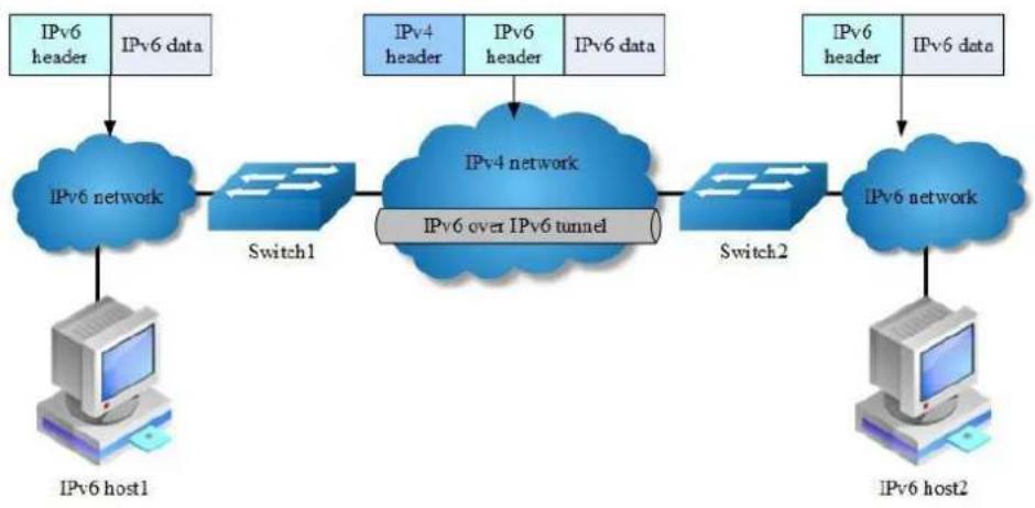
flowchart
graph LR
A["IPv6 host1"] --> B["IPv6 network"]
B --> C["Switch1"]
C --> D["IPv4 network"]
D --> E["IPv6 over IPv6 tunnel"]
E --> F["Switch2"]
F --> G["IPv6 network"]
G --> H["IPv6 host2"]
I["IPv6 header"] --> B
J["IPv6 data"] --> D
K["IPv4 header"] --> D
L["IPv6 header"] --> E
M["IPv6 data"] --> G
Figure 11-1 IPv6 over IPv4 Tunnel
Overlay tunneling encapsulates IPv6 packets in IPv4 packets for delivery across an IPv4 infrastructure (a core network or the Internet. By using overlay tunnels, you can communicate with isolated IPv6 networks without upgrading the IPv4 infrastructure between them. Overlay tunnels can be configured between border
routers or between a border router and a host; however, both tunnel endpoints must support both the IPv4 and IPv6 protocol stacks. The IPv6 over IPv4 tunnel processes packets in the following ways:
A host in the IPv6 network sends an IPv6 packet to Switch1 at the tunnel source.
After determining according to the routing table that the packet needs to be forwarded through the tunnel, Switch1 encapsulates the IPv6 packet with an IPv4 header and forwards it through the physical interface of the tunnel.
Upon receiving the packet, Switch2 decapsulates the packet.
Switch2 forwards the packet according to the destination address in the de-encapsulated IPv6 packet. If the destination address is the device itself, Switch2 forwards the IPv6 packet to the upper-layer protocol for processing.
The benefit of the technique is that current ipv4 networks do not need to update on all nodes. Only the edge nodes are required to support dual stack and tunnel.
IPv6 over IPv4 tunnels are divided into manually configured tunnels and automatic tunnels, depending on how the IPv4 address of the tunnel destination is acquired:
Manually configured tunnel: The destination address of the tunnel cannot be automatically acquired through the destination IPv6 address of an IPv6 packet at the tunnel source, and must be manually configured.
Automatic tunnel: The destination address of the tunnel is an IPv6 address with an IPv4 address embedded, and the IPv4 address can be automatically acquired through the destination IPv6 address of an IPv6 packet at the tunnel source.
Normally, system supports the following types of overlay tunneling mechanisms:
Manual
6to4
Intra-site Automatic Tunnel Addressing Protocol (ISATAP)
The details of the 3 types of overlay tunneling mechanisms are described below:
Manual Tunnel
A manually configured tunnel is equivalent to a permanent link between two IPv6 domains over an IPv4 backbone. The primary use is for stable connections that
require regular secure communication between two edge routers or between an end system and an edge router, or for connection to remote IPv6 networks.
An IPv6 address is manually configured on a tunnel interface, and manually configured IPv4 addresses are assigned to the tunnel source and the tunnel destination. The host or router at each end of a configured tunnel must support both the IPv4 and IPv6 protocol stacks. Manually configured tunnels can be configured between border routers or between a border router and a host.
6to4 Tunnel
Ordinary 6to4 tunnel
An automatic 6to4 tunnel allows isolated IPv6 domains to be connected over an IPv4 network to remote IPv6 networks. The key difference between automatic 6to4 tunnels and manually configured tunnels is that the tunnel is not point-to-point; it is point-to-multipoint. In automatic 6to4 tunnels, routers are not configured in pairs because they treat the IPv4 infrastructure as a virtual non-broadcast multi-access (NBMA) link. The IPv4 address embedded in the IPv6 address is used to find the other end of the automatic tunnel.
An automatic 6to4 tunnel may be configured on a border router in an isolated IPv6 network, which creates a tunnel on a per-packet basis to a border router in another IPv6 network over an IPv4 infrastructure. The tunnel destination is determined by the IPv4 address of the border router extracted from the IPv6 address that starts with the prefix 2002::/16, where the format is 2002:border-router-IPv4-address::/48.
Following the embedded IPv4 address are 16 bits that can be used to number networks within the site. The border router at each end of a 6to4 tunnel must support both the IPv4 and IPv6 protocol stacks. 6to4 tunnels are configured between border routers or between a border router and a host.
6to4 relay
A 6to4 tunnel is only used to connect 6to4 networks, whose IP prefix must be 2002::/16. However, IPv6 network addresses with the prefix such as 2001::/16 may also be used in IPv6 networks. To connect a 6to4 network to an IPv6 network, a 6to4 router must be used as a gateway to forward packets to the IPv6 network. Such a router is called 6to4 relay router.
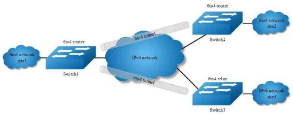
flowchart
graph LR
A["6to4 network site1"] --> B["Switch1"]
B --> C["IPv4 network"]
C --> D["Switch2"]
C --> E["Switch3"]
D --> F["6to4 router"]
E --> G["6to4 relay"]
F --> H["6to4 network site2"]
G --> I["IPv6 network site3"]
Figure 11-2 IPv6 over IPv4 Tunnel
As shown in the above figure, a static route must be configured on the border router (Switch1) in the 6to4 network and the next-hop address must be the 6to4 address of the 6to4 relay router (Switch3). In this way, all packets destined for the IPv6 network will be forwarded to the 6to4 relay router, and then to the IPv6 network. Thus, interworking between the 6to4 network (with the address prefix starting with 2002) and the IPv6 network is realized.
ISATAP Tunnel
ISATAP is an automatic overlay tunneling mechanism that uses the underlying IPv4 network as a NBMA link layer for IPv6. ISATAP is designed for transporting IPv6 packets within a site where a native IPv6 infrastructure is not yet available; for example, when sparse IPv6 hosts are deployed for testing. ISATAP tunnels allow individual IPv4 or IPv6 dual-stack hosts within a site to communicate with other such hosts on the same virtual link, basically creating an IPv6 network using the IPv4 infrastructure.
When an ISATAP tunnel is used, the destination address of an IPv6 packet and the IPv6 address of a tunnel interface both adopt special ISATAP addresses. ISATAP uses a well-defined IPv6 address format composed of any unicast IPv6 prefix (/64), which can be link local, or global (including 6to4 prefixes), enabling IPv6 routing locally or on the Internet. The IPv4 address is encoded in the last 32 bits of the IPv6 address, enabling automatic IPv6-in-IPv4 tunneling. The ISATAP address format is prefix(64bit):0:5EFE: IPv4-address.
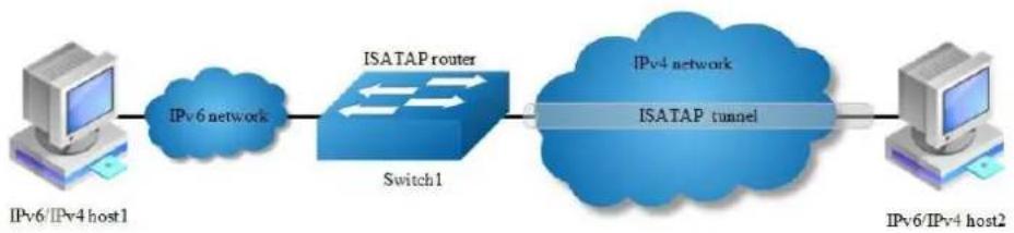
flowchart
graph LR
A["IPv6/IPv4 host1"] --> B["IPv6 network"]
B --> C["ISATAP router"]
C --> D["Switch1"]
D --> E["IPv4 network"]
E --> F["ISATAP tunnel"]
F --> G["IPv6/IPv4 host2"]
Figure 11-3 ISATAP Tunnel
The ISATAP router provides standard router advertisement network configuration support for the ISATAP site. This feature allows clients to automatically configure themselves as they would do if they were connected to an Ethernet. It can also be configured to provide connectivity out of the site.
Although the ISATAP tunneling mechanism is similar to other automatic tunneling mechanisms, such as IPv6 6to4 tunneling, ISATAP is designed for transporting IPv6 packets within a site, not between sites.
11.1.2 Configuration
Configure Manual Tunnel
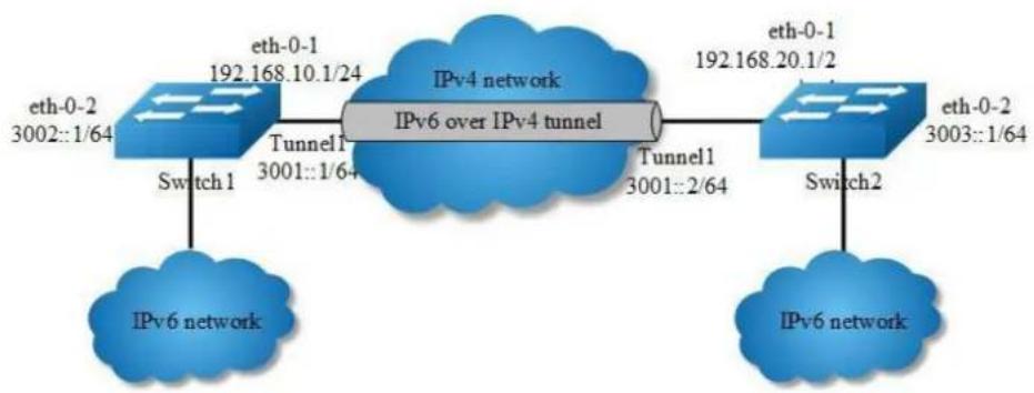
flowchart
graph LR
A["eth-0-2\n3002::1/64"] -->|Switch 1| B["IPv6 network"]
C["eth-0-1\n192.168.10.1/24"] --> D["Tunnel1\n3001::1/6+"]
D --> E["IPv4 network\nIPv6 over IPv4 tunnel"]
F["eth-0-1\n192.168.20.1/2"] --> G["Tunnel1\n3001::2/64"]
G --> H["Switch2"]
I["eth-0-2\n3003::1/64"] --> J["IPv6 network"]
K["eth-0-2\n3002::1/64"] --> L["Tunnel1\n3001::2/64"]
L --> M["Switch 2"]
Figure 11-4 Manual Tunnel
As shown in the above Figure, two IPv6 networks are connected over an IPv4 network. Configure an IPv6 manual tunnel between Switch1 and Switch2 to make the two IPv6 networks reachable to each other.

NOTE
Must enable IPv6/IPv4 dual stack before tunnel configuration.
Make sure tunnel destination is reachable in the IPv4 network.
There must exist an IPv6 address in the tunnel interface, otherwise routes with tunnel interface as nexthop will be invalid.
The following configuration should be operated on all switches if the switch ID is not specified.
step 1 Enter the configure mode
Switch# configure terminal
step 2 Enable ipv6 globally
Switch(config)# ipv6 enable
step 3 Enter the interface configure mode and set the attributes of the interface
Interface configuration for Switch1:
Switch(config)# interface eth-0-1
Switch(config-if)# no switchport
Switch(config-if)# ip address 192.168.10.1/24
Switch(config-if)# tunnel enable
Switch(config-if)# no shutdown
Switch(config-if)# exit
Switch(config)# interface eth-0-2
Switch(config-if)# no switchport
Switch(config-if)# ipv6 address 3002::1/64
Switch(config-if)# no shutdown
Switch(config-if)# exit
Switch(config)# interface tunnel1
Switch(config-if)# tunnel source eth-0-1
Switch(config-if)# tunnel destination 192.168.20.1
Switch(config-if)# tunnel mode ipv6ip
Switch(config-if)# ipv6 address 3001::1/64
Switch(config-if)# exit
Interface configuration for Switch2:
Switch(config)# interface eth-0-1
Switch(config-if)# no switchport
Switch(config-if)# ip address 192.168.20.1/24
Switch(config-if)# tunnel enable
Switch(config-if)# no shutdown
Switch(config-if)# exit
Switch(config)# interface eth-0-2
Switch(config-if)# no switchport
Switch(config-if)# ipv6 address 3003::1/64
Switch(config-if)# no shutdown
Switch(config-if)# exit
Switch(config)# interface tunnel1
Switch(config-if)# tunnel source eth-0-1
Switch(config-if)# tunnel destination 192.168.10.1
Switch(config-if)# tunnel mode ipv6ip
Switch(config-if)# ipv6 address 3001::2/64
Switch(config-if)# exit
step 4 Create static routes
Configuring Switch1:
Switch(config)# ip route 192.168.20.0/24 192.168.10.2
Switch(config)# ipv6 route 3003::/16 tunnel1
Configuring Switch2:
Switch(config)# ip route 192.168.10.0/24 192.168.20.2
Switch(config)# ipv6 route 3002::/16 tunnel1
step 5 Configuring static arp
Configuring Switch1:
Switch(config)# arp 192.168.10.2 0.0.2222
Configuring Switch2:
Switch(config)# arp 192.168.20.2 0.0.1111
step 6 Exit the configure mode
Switch(config)# end
step 7 Validation
Display the result on Switch1:
Switch# show interface tunnel1
Interface tunnel1
Interface current state: UP
Hardware is Tunnel
Index 8193, Metric 1, Encapsulation TUNNEL
VRF binding: not bound
Tunnel protocol/transport IPv6/IP, Status Valid
Tunnel source 192.168.10.1(eth-0-1), destination 192.168.20.1
Tunnel DSCP inherit, Tunnel TTL 64
Tunnel transport MTU 1480 bytes
Switch1# show ipv6 interface tunnel1
Interface current state: UP
The maximum transmit unit is 1480 bytes
IPv6 is enabled, link-local address is fe80::c0a8:a01
Global unicast address(es):
3001::1, subnet is 3001::/64
ICMP error messages limited to one every 1000 milliseconds
ICMP redirects are always sent
ND DAD is enabled, number of DAD attempts: 1
ND router advertisement is disabled
ND reachable time is 30000 milliseconds
ND advertised reachable time is 0 milliseconds
ND retransmit interval is 1000 milliseconds
ND advertised retransmit interval is 0 milliseconds
ND router advertisements max interval: 600 secs
ND router advertisements min interval: 198 secs
ND router advertisements live for 1800 seconds
ND router advertisements hop-limit is 0
Hosts use stateless autoconfig for addresses.
Display the result on Switch2:
Switch# show interface tunnel1
Interface tunnel1
Interface current state: UP
Hardware is Tunnel
Index 8193, Metric 1, Encapsulation TUNNEL
VRF binding: not bound
Tunnel protocol/transport IPv6/IP, Status Valid
Tunnel source 192.168.20.1(eth-0-1), destination 192.168.10.1
Tunnel DSCP inherit, Tunnel TTL 64
Tunnel transport MTU 1480 bytes
Switch1# show ipv6 interface tunnel1
Interface current state: UP
The maximum transmit unit is 1480 bytes
IPv6 is enabled, link-local address is fe80::c0a8:1401
Global unicast address(es):
3001::2, subnet is 3001::/64
ICMP error messages limited to one every 1000 milliseconds
ICMP redirects are always sent
ND DAD is enabled, number of DAD attempts: 1
ND router advertisement is disabled
ND reachable time is 30000 milliseconds
ND advertised reachable time is 0 milliseconds
ND retransmit interval is 1000 milliseconds
ND advertised retransmit interval is 0 milliseconds
ND router advertisements max interval: 600 secs
ND router advertisements min interval: 198 secs
ND router advertisements live for 1800 seconds
ND router advertisements hop-limit is 0
Hosts use stateless autoconfig for addresses.
Configure 6to4 Tunnel
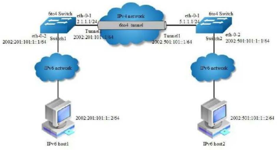
flowchart
graph TD
A["IPv6 host1"] --> B["IPv6 network"]
C["IPv6 host2"] --> D["IPv6 network"]
E["6to4 Switch"] --> F["Tunnel1: 2.1.1.1/24"]
F --> G["IPv4 network: 6to4 tunnel"]
G --> H["6to4 Switch: eth-0-1 5.1.1.1/24"]
H --> I["Switch2: eth-0-2 2002-501:101:1-1/64"]
B --> J["eth-0-2 2002:201:101:1-1/64"]
D --> K["eth-0-2 2002:501:101:1-2/64"]
Figure 11-5 6to4 tunnel
As shown in the above Figure, two 6to4 networks are connected to an IPv4 network through two 6to4 routers (Switch1 and Switch2) respectively. Configure a 6to4 tunnel to make Host1 and Host2 reachable to each other.
To enable communication between 6to4 networks, you need to configure 6to4 addresses for 6to4 routers and hosts in the 6to4 networks.
The IPv4 address of eth-0-1 on Switch1 is 2.1.1.1/24, and the corresponding 6to4 prefix is 2002:0201:0101::/48 after it is translated to an IPv6 address. Assign interface tunnel 1 to subnet 2002:0201:0101::/64 and eth-0-2 to subnet 2002:0201:0101:1::/64.
The IPv4 address of eth-0-1 on Switch2 is 5.1.1.1/24, and the corresponding 6to4 prefix is 2002:0501:0101::/48 after it is translated to an IPv6 address. Assign interface tunnel 1 to subnet 2002:0501:0101::/64 and eth-0-2 to subnet 2002:0501:0101:1::/64.

NOTE
No destination address needs to be configured for a 6to4 tunnel
The automatic tunnel interfaces using the same encapsulation protocol cannot share the same source IP address
To encapsulate and forward IPv6 packets whose destination address does not belong to the network segment where the receiving tunnel interface resides,
you need to configure a static route to reach the destination IPv6 address through this tunnel interface on the router. Because automatic tunnels do not support dynamic routing, you can configure a static route to that destination IPv6 address with this tunnel interface as the outbound interface or the peer tunnel interface address as the next hop
Only on4 6to4 tunnel can exist in the same node.
The following configuration should be operated on all switches if the switch ID is not specified.
step 1 Enter the configure mode
Switch# configure terminal
step 2 Enable ipv6 globally
Switch(config)# ipv6 enable
step 3 Enter the interface configure mode and set the attributes of the interface
Interface configuration for Switch1:
Switch(config)# interface eth-0-1
Switch(config-if)# no switchport
Switch(config-if)# ip address 2.1.1.1/24
Switch(config-if)# tunnel enable
Switch(config-if)# no shutdown
Switch(config-if)# exit
Switch(config)# interface eth-0-2
Switch(config-if)# no switchport
Switch(config-if)# ipv6 address 2002:201:101:1::1/64
Switch(config-if)# no shutdown
Switch(config-if)# exit
Switch(config)# interface tunnel1
Switch(config-if)# tunnel source eth-0-1
Switch(config-if)# tunnel mode ipv6ip 6to4
Switch(config-if)# ipv6 address 2002:201:101::1/64
Switch(config-if)# exit
Interface configuration for Switch2:
Switch(config)# interface eth-0-1
Switch(config-if)# no switchport
Switch(config-if)# ip address 5.1.1.1/24
Switch(config-if)# tunnel enable
Switch(config-if)# no shutdown
Switch(config-if)# exit
Switch(config)# interface eth-0-2
Switch(config-if)# no switchport
Switch(config-if)# ipv6 address 2002:501:101:1::1/64
Switch(config-if)# no shutdown
Switch(config-if)# exit
Switch(config)# interface tunnel1
Switch(config-if)# tunnel source eth-0-1
Switch(config-if)# tunnel mode ipv6ip 6to4
Switch(config-if)# ipv6 address 2002:501:101::1/64
Switch(config-if)# exit
step 4 Create static routes
Configuring Switch1:
Switch(config)# ip route 5.1.1.0/24 2.1.1.2
Switch(config)# ipv6 route 2002::/16 tunnel1
Configuring Switch2:
Switch(config)# ip route 2.1.1.0/24 5.1.1.2
Switch(config)# ipv6 route 2002::/16 tunnel1
step 5 Configuring static arp
Configuring Switch1:
Switch(config)# arp 2.1.1.2 0.0.2222
Configuring Switch2:
Switch(config)# arp 5.1.1.2 0.0.1111
step 6 Exit the configure mode
Switch(config)# end
step 7 Validation
Display the result on Switch1:
Switch1# show interface tunnel1
Interface tunnel1
Interface current state: UP
Hardware is Tunnel
Index 8193, Metric 1, Encapsulation TUNNEL
VRF binding: not bound
Tunnel protocol/transport IPv6/IP 6to4, Status Valid
Tunnel source 2.1.1.1(eth-0-1), destination UNKNOWN
Tunnel DSCP inherit, Tunnel TTL 64
Tunnel transport MTU 1480 bytes
Display the result on Switch2:
Switch2# show interface tunnell
Interface tunnell
Interface current state: UP
Hardware is Tunnel
Index 8193, Metric 1, Encapsulation TUNNEL
VRF binding: not bound
Tunnel protocol/transport IPv6/IP 6to4, Status Valid
Tunnel source 5.1.1.1(eth-0-1), destination UNKNOWN
Tunnel DSCP inherit, Tunnel TTL 64
Tunnel transport MTU 1480 bytes
Configure 6to4 relay
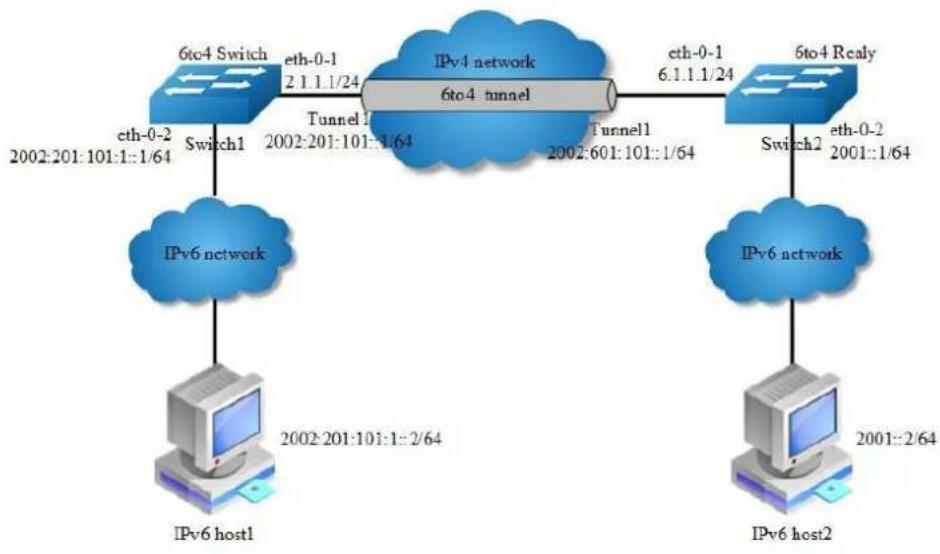
flowchart
graph TD
A["IPv6 network"] -->|2002-201:101:1:2/64| B["IPv6 host1"]
C["IPv4 network"] -->|2002-201:101:1:64| D["Tunnel1"]
D -->|2002-201:101:1:64| E["Tunnel1"]
E -->|2002-601:101:1/64| F["Tunnel1"]
F -->|2002-601:101:1/64| G["Tunnel1"]
G -->|2002-601:101:1/64| H["Tunnel1"]
H -->|2002-601:101:1/64| I["Tunnel1"]
I -->|2002-601:101:1/64| J["Tunnel1"]
J -->|2002-601:101:1/64| K["Tunnel1"]
K -->|2002-601:101:1/64| L["Tunnel1"]
L -->|2002-601:101:1/64| M["Tunnel1"]
M -->|2002-601:101:1/64| N["Tunnel1"]
N -->|2002-601:101:1/64| O["Tunnel1"]
O -->|2002-601:101:1/64| P["Tunnel1"]
P -->|2002-601:101:1/64| Q["Tunnel1"]
Q -->|2002-601:101:1/64| R["Tunnel1"]
R -->|2002-601:101:1/64| S["Tunnel1"]
S -->|2002-601:101:1/64| T["Tunnel1"]
T -->|2002-601:101:1/64| U["Tunnel1"]
U -->|2002-601:101:1/64| V["Tunnel1"]
V -->|2002-601:101:1/64| W["Tunnel1"]
W -->|2002-601:101:1/64| X["Tunnel1"]
X -->|2002-601:101:1/64| Y["Tunnel1"]
Y -->|2002-601:101:1/64| Z["Tunnel1"]
Z -->|2002-601:101:1/64| AA["Tunnel1"]
AA -->|2002-601:101:1/64| AB["Tunnel1"]
AB -->|2002-601:101:1/64| AC["Tunnel1"]
AC -->|2002-601:101:1/64| AD["Tunnel1"]
AD -->|2002-601:101:1/64| AE["Tunnel1"]
AE -->|2002-601:101:1/64| AF["Tunnel1"]
AF -->|2002-601:101:1/64| AG["Tunnel1"]
AG -->|2002-601:101:1/64| AH["Tunnel1"]
AH -->|2002-601:101:1/64| AI["Tunnel1"]
AI -->|2002-601:101:1/64| AJ["Tunnel1"]
AJ -->|2002-601:101:1/64| AK["Tunnel1"]
AK -->|2002-601:101:1/64| AL["Tunnel1"]
AL -->|2002-601:101:1/64| AM["Tunnel1"]
AM -->|2002-601:101:1/64| AN["Tunnel1"]
AN -->|2002-601:101:1/64| AO["Tunnel1"]
AO -->|2002-601:101:1/64| AP["Tunnel1"]
AP -->|2002-601:101:1/64| AQ["Tunnel1"]
AQ -->|2002-601:101:1/64| AR["Tunnel1"]
AR -->|2002-601:101:1/64| AS["Tunnel1"]
AS -->|2002-601:101:1/64| AT["Tunnel 3"]
AT -->|2002-607:589.58957899777777777777777777777777777777777777777777777777777777777777777777777777777777777777777777777777777788
Figure 11-6 6to4 relay
As shown in the above Figure, Switch1 is a 6to4 router, and 6to4 addresses are used on the connected IPv6 network. Switch2 serves as a 6to4 relay router and is connected to the IPv6 network (2001::/16). Configure a 6to4 tunnel between Router A and Router B to make Host A and Host B reachable to each other.

NOTE
The configuration on a 6to4 relay router is similar to that on a 6to4 router. However, to enable communication between the 6to4 network and the IPv6 network, you need to configure a route to the IPv6 network on the 6to4 router.
It is not allowed to change the tunnel mode from 6to4 to ISATAP when there are any 6to4 relay routes existing. You must delete this route first.
The following configuration should be operated on all switches if the switch ID is not specified.
step 1 Enter the configure mode
Switch# configure terminal
step 2 Enable ipv6 globally
Switch(config)# ipv6 enable
step 3 Enter the interface configure mode and set the attributes of the interface
Interface configuration for Switch1:
Switch(config)# interface eth-0-1
Switch(config-if)# no switchport
Switch(config-if)# ip address 2.1.1.1/24
Switch(config-if)# tunnel enable
Switch(config-if)# no shutdown
Switch(config-if)# exit
Switch(config)# interface eth-0-2
Switch(config-if)# no switchport
Switch(config-if)# ipv6 address 2002:201:101:1::1/64
Switch(config-if)# no shutdown
Switch(config-if)# exit
Switch(config)# interface tunnel1
Switch(config-if)# tunnel source eth-0-1
Switch(config-if)# tunnel mode ipv6ip 6to4
Switch(config-if)# ipv6 address 2002:201:101::1/64
Switch(config-if)# exit
Interface configuration for Switch2:
Switch(config)# interface eth-0-1
Switch(config-if)# no switchport
Switch(config-if)# ip address 5.1.1.1/24
Switch(config-if)# tunnel enable
Switch(config-if)# no shutdown
Switch(config-if)# exit
Switch(config)# interface eth-0-2
Switch(config-if)# no switchport
Switch(config-if)# ipv6 address 2002:501:101:1::1/64
Switch(config-if)# no shutdown
Switch(config-if)# exit
Switch(config)# interface tunnel1
Switch(config-if)# tunnel source eth-0-1
Switch(config-if)# tunnel mode ipv6ip 6to4
Switch(config-if)# ipv6 address 2002:501:101::1/64
Switch(config-if)# exit
step 4 Create static routes
Configuring Switch1:
Switch(config)# ip route 6.1.1.0/24 2.1.1.2
Switch(config)# ipv6 route 2001::/16 2002:601:101::1
Switch(config)# ipv6 route 2002:601:101::/48 tunnel1
Configuring Switch2:
Switch(config)# ip route 2.1.1.0/24 6.1.1.2
Switch(config)# ipv6 route 2002::/16 tunnel1
step 5 Configuring static arp
Configuring Switch1:
Switch(config)# arp 2.1.1.2 0.0.2222
Configuring Switch2:
Switch(config)# arp 6.1.1.2 0.0.1111
step 6 Exit the configure mode
Switch(config)# end
step 7 Validation
Display the result on Switch1:
Switch# show interface tunnel1
Interface tunnel1
Interface current state: UP
Hardware is Tunnel
Index 8193, Metric 1, Encapsulation TUNNEL
VRF binding: not bound
Tunnel protocol/transport IPv6/IP 6to4, Status Valid
Tunnel source 2.1.1.1(eth-0-1), destination UNKNOWN
Tunnel DSCP inherit, Tunnel TTL 64
Tunnel transport MTU 1480 bytes
Switch# show ipv6 route
IPv6 Routing Table
Codes: C - connected, S - static, R - RIP, O - OSPF, I - IS-IS, B - BGP [*] - [AD/Metric]
Timers: Uptime
S 2001::/16 [1/0]
via 2002:601:101::1 (recursive via ::, tunnel1), 00:00:32
C 2002:201:101::/64
via ::, tunnel1, 00:00:04
C 2002:201:101::1/128
via ::1, tunnel1, 00:00:04
S 2002:601:101::/48 [1/0]
via ::, tunnel1, 00:00:22
Switch# show ipv6 interface tunnel1
Interface tunnel1
Interface current state: UP
The maximum transmit unit is 1480 bytes
IPv6 is enabled, link-local address is fe80::201:101
Global unicast address(es):
2002:201:101::1, subnet is 2002:201:101::/64
ICMP error messages limited to one every 1000 milliseconds
ICMP redirects are always sent
ND DAD is enabled, number of DAD attempts: 1
ND router advertisement is disabled
ND reachable time is 30000 milliseconds
ND advertised reachable time is 0 milliseconds
ND retransmit interval is 1000 milliseconds
ND advertised retransmit interval is 0 milliseconds
ND router advertisements max interval: 600 secs
ND router advertisements min interval: 198 secs
ND router advertisements live for 1800 seconds
ND router advertisements hop-limit is 0
Hosts use stateless autoconfig for addresses.
Display the result on Switch2:
Switch# show interface tunnel1
Interface tunnel1
Interface current state: UP
Hardware is Tunnel
Index 8193, Metric 1, Encapsulation TUNNEL
VRF binding: not bound
Tunnel protocol/transport IPv6/IP 6to4, Status Valid
Tunnel source 6.1.1.1(eth-0-1), destination UNKNOWN
Tunnel DSCP inherit, Tunnel TTL 64
Tunnel transport MTU 1480 bytes
Configure ISATAP Tunnel
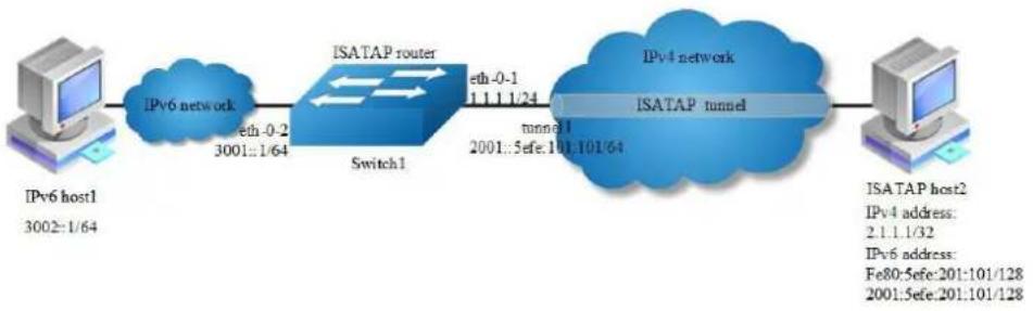
flowchart
graph LR
A["IPv6 host1<br>3002:1/64"] --> B["IPv6 network"]
B --> C["ISATAP router<br>Switch1"]
C --> D["eth-0-1<br>1.1.1.24<br>2001::5efe:101.101/64"]
D --> E["IPv4 network<br>ISATAP tunnel"]
E --> F["ISATAP host2<br>IPv4 address:<br>2.1.1.32<br>IPv6 address:<br>Fe80:5efe:201:101/128<br>2001:5efe:201:101/128"]
Figure 11-7 ISATAP tunnel
As shown in the above Figure, an IPv6 network is connected to an IPv4 network through an ISATAP router. It is required that the IPv6 host in the IPv4 network can access the IPv6 network through the ISATAP tunnel.

NOTE
No destination address needs to be configured for a ISATAP tunnel
The automatic tunnel interfaces using the same encapsulation protocol cannot share the same source IP address
To encapsulate and forward IPv6 packets whose destination address does not belong to the network segment where the receiving tunnel interface resides, you need to configure a static route to reach the destination IPv6 address through this tunnel interface on the router. Because automatic tunnels do not support dynamic routing, you can configure a static route to that destination IPv6 address with this tunnel interface as the outbound interface or the peer tunnel interface address as the next hop
step 1 Enter the configure mode
Switch# configure terminal
step 2 Enable ipv6 globally
Switch(config)# ipv6 enable
step 3 Enter the interface configure mode and set the attributes of the interface
Switch(config)# interface eth-0-1
Switch(config-if)# no switchport
Switch(config-if)# ip address 1.1.1.1/24
Switch(config-if)# tunnel enable
Switch(config-if)# no shutdown
Switch(config-if)# exit
Switch(config)# interface eth-0-2
Switch(config-if)# no switchport
Switch(config-if)# ipv6 address 3001::1/64
Switch(config-if)# no shutdown
Switch(config-if)# exit
Switch(config)# interface tunnel1
Switch(config-if)# tunnel source eth-0-1
Switch(config-if)# tunnel mode ipv6ip isatap
Switch(config-if)# ipv6 address 2001::/64 eui-64
Switch(config-if)# no ipv6 nd ra suppress
Switch(config-if)# exit
step 4 Create static routes
Switch(config)# ip route 2.1.1.0/24 1.1.1.2
Switch(config)# ipv6 route 2001::/16 tunnel1
step 5 Configuring static arp
Switch(config)# arp 1.1.1.2 0.0.2222
step 6 Exit the configure mode
Switch(config)# end
step 7 Validation
Switch# show interface tunnel1
Interface tunnel1
Interface current state: UP
Hardware is Tunnel
Index 8193, Metric 1, Encapsulation TUNNEL
VRF binding: not bound
Tunnel protocol/transport IPv6/IP ISATAP, Status Valid
Tunnel source 1.1.1.1(eth-0-1), destination UNKNOWN
Tunnel DSCP inherit, Tunnel TTL 64
Tunnel transport MTU 1480 bytes
Switch# show ipv6 interface tunnel1
Interface tunnel1
Interface current state: UP
The maximum transmit unit is 1480 bytes
IPv6 is enabled, link-local address is fe80::101:101
Global unicast address(es):
2001::101:101, subnet is 2001::/64 [EUI]
ICMP error messages limited to one every 1000 milliseconds
ICMP redirects are always sent
ND DAD is enabled, number of DAD attempts: 1
ND router advertisement is enabled
ND reachable time is 30000 milliseconds
ND advertised reachable time is 0 milliseconds
ND retransmit interval is 1000 milliseconds
ND advertised retransmit interval is 0 milliseconds
ND router advertisements max interval: 600 secs
ND router advertisements min interval: 198 secs
ND next router advertisement due in 359 secs.
ND router advertisements live for 1800 seconds
ND router advertisements hop-limit is 0
Hosts use stateless autoconfig for addresses.
Configure ISATAP host
The specific configuration on the ISATAP host is related to its operating system. The following example shows the configuration of the host running the Windows XP.
Install IPv6.
C:\>ipv6 install
On a Windows XP-based host, the ISATAP interface is usually interface 2. Configure the IPv4 address of the ISATAP router on interface 2 to complete the configuration on the host. Before that, display information on the ISATAP interface:
Interface 2: Automatic Tunneling Pseudo-Interface
Guid {48FCE3FC-EC30-E50E-F1A7-71172AEEE3AE}
does not use Neighbor Discovery
does not use Router Discovery
routing preference 1
EUI-64 embedded IPv4 address: 0.0.0.0
router link-layer address: 0.0.0.0
preferred link-local fe80::5efe:2.1.1.1, life infinite
link MTU 1280 (true link MTU 65515)
current hop limit 128
reachable time 25000ms (base 30000ms)
retransmission interval 1000ms
DAD transmits 0
default site prefix length 48
A link-local address (fe80::5efe:2.1.1.2) in the ISATAP format was automatically generated for the ISATAP interface. Configure the IPv4 address of the ISATAP router on the ISATAP interface.
C:\>ipv6 rlu 2 1.1.1.1
After carrying out the above command, look at the information on the ISATAP interface.
Interface 2: Automatic Tunneling Pseudo-Interface
Guid {48FCE3FC-EC30-E50E-F1A7-71172AEEE3AE}
does not use Neighbor Discovery
does not use Router Discovery
routing preference 1
EUI-64 embedded IPv4 address: 2.1.1.1
router link-layer address: 1.1.1.1
preferred global 2001::5efe:2.1.1.1, life 29d23h59m46s/6d23h59m46s (public)
preferred link-local fe80::5efe:2.1.1.1, life infinite
link MTU 1280 (true link MTU 65515)
current hop limit 128
reachable time 25000ms (base 30000ms)
retransmission interval 1000ms
DAD transmits 0
default site prefix length 48
11.1.3 Application cases
N/A
11.2 Configuring ND
11.2.1 Overview
Function Introduction
Nodes (hosts and routers) use Neighbor Discovery to determine the link-layer addresses for neighbors known to reside on attached links and to quickly purge cached values that become invalid.
Hosts also use Neighbor Discovery to find neighboring routers that are willing to forward packets on their behalf.
Finally, nodes use the protocol to actively keep track of which neighbors are reachable and which are not, and to detect changed link-layer addresses. When a router or the path to a router fails, a host actively searches for functioning alternates.
Principle Description
N/A
11.2.2 Configuration
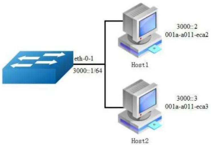
flowchart
graph TD
A["Router"] -->|eth-0-1 3000::1/64| B["Host1"]
A -->|3000::2 001a-a011-eca2| C["Host2"]
A -->|3000::3 001a-a011-eca3| D["Host2"]
Figure 11-8 NDP
In this example, interface eth-0-1 assigned with ipv6 address 3000::1/64, on subnet 3000::/64, there are two hosts, and their IP addresses are 3000::2, 3000::3, MAC address are 001a-a011-eca2, 001a-a011-eca3. Neighbor entry of host 3000::2 is added manually, the entry of host 3000::3 is added dynamically. The reachable time of neighbor entries for interface eth-0-1 configure to 10 minutes, NS interval on interface eth-0-1 configure to 2 seconds.
step 1 Enter the configure mode
Switch# configure terminal
step 2 Enter the interface configure mode and set the attributes of the interface
Switch (config)# interface eth-0-1
Switch (config-if)# no switchport
Switch (config-if)# no shutdown
Switch (config-if)# ipv6 address 3000::1/64
Switch (config-if)# ipv6 nd reachable-time 600
Switch (config-if)# ipv6 nd ns-interval 2000
Switch (config-if)# exit
step 3 Add a static neighbor entry
Switch (config)# ipv6 neighbor 3000::2 001a.a011.eca2
step 4 Exit the configure mode
Switch(config)# end
step 5 Validation
Switch # show ipv6 neighbors
IPv6 address Age Link-Layer Addr State Interface
3000::2 - 001a-a011-eca2 REACH eth-0-1
3000::3 6 001a-a011-eca3 REACH eth-0-1
fe80::6d8:e8ff:fe4c:e700 6 001a-a011-eca3 STALE eth-0-1
11.2.3 Application cases
N/A
11.3 Configuring DHCPv6 Relay
11.3.1 Overview
Function Introduction
DHCPv6 relay is any host that forwards DHCPv6 packets between clients and servers. Relay is used to forward requests and replies between clients and servers when they are not on the same physical subnet. Relay forwarding is distinct from the normal forwarding of an IPv6 router, where IPv6 datagram are switched between networks somewhat transparently.
By contrast, relay receive DHCPv6 messages and then generate a new DHCPv6 message to send out on another interface. The relay sets the link address (used by server to identify the subnet that client is belong to), and, if configured, adds the remote-id option in the packet and forwards it to the DHCPv6 server..
Principle Description
N/A
11.3.2 Configuration
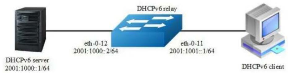
flowchart
graph LR
A["DHCPv6 server\n2001:1000::1/64"] -->|eth-0-12\n2001:1000::2/64| B["DHCPv6 relay"]
B -->|eth-0-11\n2001:1001::1/64| C["DHCPv6 client"]
Figure 11-9 DHCP Relay
This figure is the networking topology for testing DHCPv6 relay functions. We need two Linux boxes and one Switch to construct the test bed.
➢ Computer A is used as DHCPv6 server.
Computer B is used as DHCPv6 client.
Switch is used as DHCPv6 relay.
step 1 Enter the configure mode
Switch# configure terminal
step 2 Enable DHCPv6 relay globally
Switch(config)# service dhcpv6 enable
Switch(config)# dhcpv6 relay
Switch(config)# dhcpv6 relay remote-id option
Switch(config)# dhcpv6 relay pd route
step 3 Configure the DHCPv6 server
Switch(config)# dhcpv6-server 1 2001:1000::1
step 4 Enter the interface configure mode and set the attributes of the interface
Switch(config)# interface eth-0-12
Switch(config-if)# no switchport
Switch(config-if)# ipv6 address 2001:1000::2/64
Switch(config-if)# no shutdown
Switch(config-if)# exit
Switch(config)# interface eth-0-11
Switch(config-if)# no switchport
Switch(config-if)# ipv6 address 2001:1001::1/64
Switch(config-if)# no shutdown
Switch(config-if)# dhcpv6-server 1
Switch(config-if)# exit
step 5 Exit the configure mode
Switch(config)# end
step 6 Validation
Check the interface configuration
Switch# show running-config interface eth-0-12
!
interface eth-0-12
no switchport
ipv6 address 2001:1000::1/64
!
Switch # show running-config interface eth-0-11
!
interface eth-0-11
no switchport
ipv6 address 2001:1001::1/64
dhcpv6-server 1
Check the dhcpv6 service status
Switch# show services
Networking services configuration:
Service Name Status
dhcp disable
dhcpv6 enable
Check the dhcpv6 server group configuration
Switch# show dhcpv6-server
DHCPv6 server group information:
group 1 ipv6 address list:
[1] 2001:1000::1
Check the dhcpv6 relay statistics.
Switch# show dhcpv6 relay statistics
DHCPv6 relay packet statistics:
Client relayed packets : 8
Server relayed packets : 8
Client error packets : 0
Server error packets : 0
Check the prefix-delegation client information learning by DHCPv6 relay
Switch# show dhcpv6 relay pd client
DHCPv6 prefix-delegation client information:
Interface : eth-0-11
Client DUID : 000100011804ff38c2428f04970
Client IPv6 address : fe80::beac:d8ff:fedf:c600
IA ID : d8dfc60
IA Prefix : 2002:2:9:eebe::/64
preferred/max lifetime : 280/300
expired time : 2001-1-1 09:10:58
11.3.3 Application cases
N/A
12 IPv6 Security Configuration Guide
12.1 DHCPv6 Snooping Configuration
12.1.1 Overview
Function Introduction
DHCPv6 snooping is a security feature that acts like a firewall between untrusted hosts and trusted DHCPv6 servers. The DHCPv6 snooping feature performs the following activities:
Validate DHCPv6 messages received from untrusted sources and filters out invalid messages.
Build and maintain the DHCPv6 snooping binding database, which contains information about untrusted hosts with leased IPv6 addresses.
The DHCPv6 snooping feature is implemented in software basis. All DHCPv6 messages are intercepted in the chip and directed to the CPU for processing.
Principle Description
N/A
12.1.2 Configuration
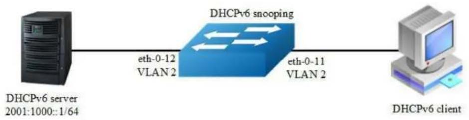
flowchart
graph LR
A["DHCPv6 server 2001:1000::1/64"] -->|eth-0-12 VLAN 2| B["DHCPv6 snooping"]
B -->|eth-0-11 VLAN 2| C["DHCPv6 client"]
Figure 12-1 DHCPv6 Snooping
This figure is the networking topology for testing DHCPv6 snooping functions. We need two PCs and one switch to construct the test bed.
PC A is used as a DHCPv6 server.
PC B is used as a DHCPv6 client.
Switch A is used as a DHCPv6 Snooping device.
step 1 Enter the configure mode
Switch# configure terminal
step 2 Enter the vlan configure mode and create the vlan
Switch(config)# vlan database
Switch(config-vlan)# vlan 2
Switch(config-vlan)# exit
step 3 Enter the interface configure mode and set the attributes of the interface
Switch(config)# interface eth-0-11
Switch(config-if)# switchport
Switch(config-if)# switchport access vlan 2
Switch(config-if)# no shutdown
Switch(config-if)# exit
Switch(config)# interface eth-0-12
Switch(config-if)# switchport
Switch(config-if)# switchport access vlan 2
Switch(config-if)# dhcpv6 snooping trust
Switch(config-if)# no shutdown
Switch(config-if)# exit
step 4 Enable DHCPv6 snooping globally and set the attributes
Switch(config)# service dhcpv6 enable
Switch(config)# dhcpv6 snooping
Switch(config)# dhcpv6 snooping vlan 2
step 5 Exit the configure mode
Switch(config)# end
step 6 Validation
Check the interface configuration.
Switch# show running-config interface eth-0-12
!
interface eth-0-12
switchport access vlan 2
dhcpv6 snooping trust
!
Switch# show running-config interface eth-0-11
!
interface eth-0-11
switchport access vlan 2
!
Check the dhcpv6 service status.
Switch# show services
Networking services configuration:
Service Name Status
dhcp disable
dhcpv6 enable
Show dhcpv6 snooping statistics.
Switch# show dhcpv6 snooping config dhcpv6 snooping service: enabled dhcpv6 snooping switch: enabled dhcpv6 snooping vlan 2
Enable DHCPv6 snooping global feature
Switch# show dhcpv6 snooping statistics
DHCPv6 snooping statistics:
DHCPv6 packets 21
Packets forwarded 21
Packets invalid 0
Packets dropped 0
Step 5 Show dhcpv6 snooping binding information
Switch# show dhcpv6 snooping binding all DHCPv6 snooping binding table:
VLAN MAC Address Lease(s) Interface IPv6 Address
2 0016.76a1.7ed9 978 eth-0-11 2001:1000::2
12.1.3 Application cases
N/A
13 IPv6 Routing Configuration
13.1 Configuring IPv6 Unicast-Routing
13.1.1 Overview
Function Introduction
Static routing is a concept describing one way of configuring path selection of routers in computer networks. It is the type of routing characterized by the absence of communication between routers regarding the current topology of the network. This is achieved by manually adding routes to the routing table. The opposite of static routing is dynamic routing, sometimes also referred to as adaptive routing.
In these systems, routes through a data network are described by fixed paths (statically). These routes are usually entered into the router by the system administrator. An entire network can be configured using static routes, but this type of configuration is not fault tolerant. When there is a change in the network or a failure occurs between two statically defined nodes, traffic will not be rerouted. This means that anything that wishes to take an affected path will either have to wait for the failure to be repaired or the static route to be updated by the administrator before restarting its journey. Most requests will time out (ultimately failing) before these repairs can be made. There are, however, times when static routes can improve the performance of a network. Some of these include stub networks and default routes.
Principle Description
N/A
13.1.2 Configuration

flowchart
graph LR
A["Switch1"] -->|eth-0-9\n2001:1::/64| B["Switch2"]
B -->|eth-0-17\n2001:2::/64| C["Switch3"]
Figure 13-1 ipv6 unicast routing
The following example shows how to deploy static routes in a simple environment.
The following configuration should be operated on all switches if the switch ID is not specified.
step 1 Enter the configure mode
Switch# configure terminal
step 2 Enable ipv6 globally
Switch(config)# ipv6 enable
step 3 Enter the interface configure mode and set the attributes of the interface
Interface configuration for Switch1:
Switch(config)# interface eth-0-9
Switch(config-if)# no switchport
Switch(config-if)# no shutdown
Switch(config-if)# ipv6 address auto link-local
Switch(config-if)# ipv6 address 2001:1::1/64
Switch(config-if)# exit
Interface configuration for Switch2:
Switch(config)# interface eth-0-9
Switch(config-if)# no switchport
Switch(config-if)# no shutdown
Switch(config-if)# ipv6 address auto link-local
Switch(config-if)# ipv6 address 2001:1::2/64
Switch(config-if)# exit
Switch(config)# interface eth-0-17
Switch(config-if)# no switchport
Switch(config-if)# no shutdown
Switch(config-if)# ipv6 address auto link-local
Switch(config-if)# ipv6 address 2001:2::2/64
Switch(config-if)# exit
Interface configuration for Switch3:
Switch(config)# interface eth-0-17
Switch(config-if)# no switchport
Switch(config-if)# no shutdown
Switch(config-if)# ipv6 address auto link-local
Switch(config-if)# ipv6 address 2001:2::3/64
Switch(config-if)# exit
step 4 Create static routes
Configuring Switch1:
Switch(config)# ipv6 route 2001:2::/64 2001:1::2
Configuring Switch3:
Switch(config)# ipv6 route 2001:1::/64 2001:2::2
step 5 Exit the configure mode
Switch(config)# end
step 6 Validation
Display the result on Switch1:
Switch# show ipv6 route
IPv6 Routing Table
Codes: C - connected, S - static, R - RIP, O - OSPF, I - IS-IS, B - BGP
[*] - [AD/Metric]
Timers: Uptime
C 2001:1::/64
via ::, eth-0-9, 02:08:50
C 2001:1::1/128
via ::1, eth-0-9, 02:08:50
S 2001:2::/64 [1/0]
via 2001:1::2, eth-0-9, 02:05:36
C fe80::/10
via ::, Null0, 02:09:11
Display the result on Switch2:
Switch# show ipv6 route
IPv6 Routing Table
Codes: C - connected, S - static, R - RIP, O - OSPF, I - IS-IS, B - BGP
[*] - [AD/Metric]
Timers: Uptime
C 2001:1::/64
via ::, eth-0-9, 00:03:37
C 2001:1::2/128
via ::1, eth-0-9, 00:03:37
C 2001:2::/64
via ::, eth-0-17, 00:03:21
C 2001:2::2/128
via ::1, eth-0-17, 00:03:21
C fe80::/10
via ::, Null0, 00:03:44
Display the result on Switch3:
Switch# show ipv6 route
IPv6 Routing Table
Codes: C - connected, S - static, R - RIP, O - OSPF, I - IS-IS, B - BGP
[*] - [AD/Metric]
Timers: Uptime
S 2001:1::/64 [1/0]
via 2001:2::2, eth-0-17, 00:02:14
C 2001:2::/64
via ::, eth-0-17, 00:03:28
C 2001:2::3/128
via ::1, eth-0-17, 00:03:28
C fe80::/10
via ::, Null0, 00:03:53
Use the "ping" command on switch1 to contact the switch3:
Switch1# ping ipv6 2001:2::3
PING 2001:2::3(2001:2::3) 56 data bytes
64 bytes from 2001:2::3: icmp_seq=0 ttl=63 time=127 ms
64 bytes from 2001:2::3: icmp_seq=1 ttl=63 time=132 ms
64 bytes from 2001:2::3: icmp_seq=2 ttl=63 time=124 ms
64 bytes from 2001:2::3: icmp_seq=3 ttl=63 time=137 ms
64 bytes from 2001:2::3: icmp_seq=4 ttl=63 time=141 ms
--- 2001:2::3 ping statistics ---
5 packets transmitted, 5 received, 0% packet loss, time 4010ms
rtt min/avg/max/mdev = 124.950/132.719/141.251/5.923 ms, pipe 2
13.1.3 Application cases
N/A
13.2 Configuring OSPFv3
13.2.1 Overview
Function Introduction
OSPF is an Interior Gateway Protocol (IGP) designed expressly for IP networks, supporting IP subnet ting and tagging of externally derived routing information.
The implementation conforms to the OSPF Version 3, which is described in RFC 5340, expands on OSPF version 2 to support IPv6 routing prefixes. Much of the OSPF for IPv6 feature is the same as in OSPF version 2. Changes between OSPF for IPv4, OSPF Version 2, and OSPF for IPv6 as described herein include the following:
➢ Addressing semantics have been removed from OSPFv3 packets and the basic Link State Advertisements (LSAs).
➢ OSPFv3 now runs on a per-link basis rather than on a per-IP-subnet basis.
➢ Authentication has been removed from the OSPFv3 protocol.
Principle Description
The OSPFv3 module is based on the following RFC: RFC 5340 - OSPF for IPv6
13.2.2 Configuration
Basic OSPFv3 Parameters Configuration
step 1 Enter the configure mode
Switch# configure terminal
step 2 Create OSPFv3 instance
Switch(config)# router ipv6 ospf 100
Switch(config-router)# router-id 1.1.1.1
Switch(config-router)# exit

NOTE
Use the command "no router ipv6 ospf process-id" in global to delete the OSPFv3 instance.
step 3 Exit the configure mode
Switch(config)# end
step 4 Validation
Switch# show ipv6 protocols
Routing Protocol is "OSPFv3 (100)" with ID 1.1.1.1
Redistributing:
Routing for Networks:
Distance: (default is 110)
Enabling OSPFv3 on an Interface
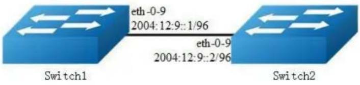
Figure 13-2 OSPFv3
This example shows the minimum configuration required for enabling OSPFv3 on an interface Switch1 and 2 are two routers in Area 0 connecting to prefix 2004:12:9::/96.
The following configuration should be operated on all switches if the switch ID is not specified.
step 1 Enter the configure mode
Switch# configure terminal
step 2 Enable ipv6 globally
Switch(config)# ipv6 enable
step 3 Create OSPFv3 instance
Configuring Switch1:
Switch(config)# router ipv6 ospf 100
Switch(config-router)# router-id 1.1.1.1
Switch(config-router)# exit
Configuring Switch2:
Switch(config)# router ipv6 ospf 200
Switch(config-router)# router-id 2.2.2.2
Switch(config-router)# exit
step 4 Enter the interface configure mode and set the attributes of the interface
Interface configuration for Switch1:
Switch(config)# interface eth-0-9
Switch(config-if)# no switchport
Switch(config-if)# no shutdown
Switch(config-if)# ipv6 address 2004:12:9::1/96
Switch(config-if)# ipv6 router ospf 100 area 0 instance 0
Switch(config-if)# exit
Interface configuration for Switch2:
Switch(config)# interface eth-0-9
Switch(config-if)# no switchport
Switch(config-if)# no shutdown
Switch(config-if)# ipv6 address 2004:12:9::2/96
Switch(config-if)# ipv6 router ospf 200 area 0 instance 0
Switch(config-if)# exit
step 3 Exit the configure mode
Switch(config)# end
step 4 Validation
Display the result on Switch1:
Switch# show ipv6 ospf database
OSPFv3 Router with ID (1.1.1.1) (Process 100)
Link-LSA (Interface eth-0-9)
Link State ID ADV Router Age Seq# CkSum Prefix
0.0.0.9 1.1.1.1 614 0x80000001 0x6a40 1
0.0.0.9 2.2.2.2 68 0x80000001 0x4316 1
Router-LSA (Area 0.0.0.0)
Link State ID ADV Router Age Seq# CkSum Link
0.0.0.0 1.1.1.1 54 0x80000003 0xb74b 1
0.0.0.0 2.2.2.2 55 0x80000003 0x9965 1
Network-LSA (Area 0.0.0.0)
Link State ID ADV Router Age Seq# CkSum
0.0.0.9 1.1.1.1 54 0x80000001 0x3edl
Intra-Area-Prefix-LSA (Area 0.0.0.0)
Link State ID ADV Router Age Seq# CkSum Prefix Reference
0.0.0.2 1.1.1.1 53 0x80000001 0x450a 1 Network-LSA
Switch# show ipv6 ospf neighbor
OSPFv3 Process (100)
Neighbor ID Pri State Dead Time Interface Instance ID
2.2.2.2 1 Full/Backup 00:00:33 eth-0-9 0
Switch# show ipv6 ospf route
OSPFv3 Process (100)
Codes: C - connected, D - Discard, O - OSPF, IA - OSPF inter area
E1 - OSPF external type 1, E2 - OSPF external type 2
Destination Metric
Next-hop
C 2004:12:9::/96 1
directly connected, eth-0-9, Area 0.0.0.0
Display the result on Switch2:
Switch# show ipv6 ospf database
OSPFv3 Router with ID (2.2.2.2) (Process 200)
Link-LSA (Interface eth-0-9)
Link State ID ADV Router Age Seq# CkSum Prefix
0.0.0.9 1.1.1.1 774 0x80000001 0x6a40 1
0.0.0.9 2.2.2.2 228 0x80000001 0x4316 1
Router-LSA (Area 0.0.0.0)
Link State ID ADV Router Age Seq# CkSum Link
0.0.0.0 1.1.1.1 217 0x80000003 0xb74b 1
0.0.0.0 2.2.2.2 214 0x80000003 0x9965 1
Network-LSA (Area 0.0.0.0)
Link State ID ADV Router Age Seq# CkSum
0.0.0.9 1.1.1.1 215 0x80000001 0x3ed1
Intra-Area-Prefix-LSA (Area 0.0.0.0)
Link State ID ADV Router Age Seq# CkSum Prefix Reference
0.0.0.2 1.1.1.1 214 0x80000001 0x450a 1 Network-LSA
Switch# show ipv6 ospf neighbor
OSPFv3 Process (200)
Neighbor ID Pri State Dead Time Interface Instance ID
1.1.1.1 1 Full/DR 00:00:35 eth-0-9 0
Switch# show ipv6 ospf route
OSPFv3 Process (200)
Codes: C - connected, D - Discard, O - OSPF, IA - OSPF inter area
E1 - OSPF external type 1, E2 - OSPF external type 2
Destination Metric
Next-hop
C 2004:12:9::/96 1
directly connected, eth-0-9, Area 0.0.0.0
Configuring Priority
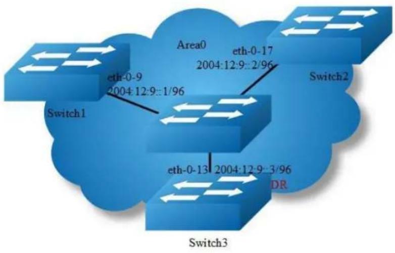
flowchart
graph TD
Switch1["Switch1"] -->|eth-0-9 2004:12:9::1/96| Switch2["Switch2"]
Switch2 -->|eth-0-17 2004:12:9::2/96| Switch3["Switch3"]
Switch3 -->|eth-0-13 2004:12:9::3/96 DR| Switch1
Switch1 -->|Area0| Switch2
Switch3 -->|DR| Switch3
Figure 13-3 OSPFv3 priority
This example shows the configuration for setting the priority for an interface. You can set a high priority for a router to make it the Designated Router (DR). Router Switch3 is configured to have a priority of 10, which is higher than the default priority (default priority is 1) of Switch1 and 2; making it the DR.
The following configuration should be operated on all switches if the switch ID is not specified.
step 1 Enter the configure mode
Switch# configure terminal
step 2 Enable ipv6 globally
Switch(config)# ipv6 enable
step 3 Create OSPFv3 instance
Configuring Switch1:
Switch(config)# router ipv6 ospf 100
Switch(config-router)# router-id 1.1.1.1
Switch(config-router)# exit
Configuring Switch2:
Switch(config)# router ipv6 ospf 200
Switch(config-router)# router-id 2.2.2.2
Switch(config-router)# exit
Configuring Switch3:
Switch(config)# router ipv6 ospf 300
Switch(config-router)# router-id 3.3.3.3
Switch(config-router)# exit
step 4 Enter the interface configure mode and set the attributes of the interface
Interface configuration for Switch1:
Switch(config)# interface eth-0-9
Switch(config-if)# no switchport
Switch(config-if)# no shutdown
Switch(config-if)# ipv6 address 2004:12:9::1/96
Switch(config-if)# ipv6 router ospf 100 area 0 instance 0
Switch(config-if)# exit
Interface configuration for Switch2:
Switch(config)# interface eth-0-17
Switch(config-if)# no switchport
Switch(config-if)# no shutdown
Switch(config-if)# ipv6 address 2004:12:9::2/96
Switch(config-if)# ipv6 router ospf 200 area 0 instance 0
Switch(config-if)# exit
Interface configuration for Switch3:
Switch(config)# interface eth-0-13
Switch(config-if)# no switchport
Switch(config-if)# no shutdown
Switch(config-if)# ipv6 address 2004:12:9::3/96
Switch(config-if)# ipv6 router ospf 300 area 0 instance 0
Switch(config-if)# ipv6 ospf priority 10
Switch(config-if)# exit
step 5 Exit the configure mode
Switch(config)# end
step 6 Validation
Display the result on Switch1:
Switch# show ipv6 ospf neighbor
OSPFv3 Process (100)
Neighbor ID Pri State Dead Time Interface Instance ID
2.2.2.2 1 Full/Backup 00:00:31 eth-0-9 0
3.3.3.3 10 Full/DR 00:00:36 eth-0-9 0
Switch#
Switch# show ipv6
interface isis mif mld mroute mroute-rpf
multicast neighbors ospf pim prefix-list protocols
rip route
Switch# show ipv6 ospf interface
eth-0-9 is up, line protocol is up
Interface ID 9
IPv6 Prefixes
fe80::20e6:7eff:fee2:d400/10 (Link-Local Address)
2004:12:9::1/96
OSPFv3 Process (100), Area 0.0.0.0, Instance ID 0
Router ID 1.1.1.1, Network Type BROADCAST, Cost: 1
Transmit Delay is 1 sec, State DROther, Priority 1
Designated Router (ID) 3.3.3.3
Interface Address fe80::ba5d:79ff:fe55:ed00
Backup Designated Router (ID) 2.2.2.2
Interface Address fe80::fcc8:7bff:fe3e:ec00
Timer interval configured, Hello 10, Dead 40, Wait 40, Retransmit 5
Hello due in 00:00:03
Neighbor Count is 2, Adjacent neighbor count is 2
Display the result on Switch2:
Switch# show ipv6 ospf neighbor
OSPFv3 Process (200)
Neighbor ID Pri State Dead Time Interface Instance ID
1.1.1.1 1 Full/DROther 00:00:31 eth-0-17 0
3.3.3.3 10 Full/DR 00:00:37 eth-0-17 0
Switch# show ipv6 ospf interface
eth-0-17 is up, line protocol is up
Interface ID 17
IPv6 Prefixes
fe80::fcc8:7bff:fe3e:ec00/10 (Link-Local Address)
2004:12:9::2/96
OSPFv3 Process (200), Area 0.0.0.0, Instance ID 0
Router ID 2.2.2.2, Network Type BROADCAST, Cost: 1
Transmit Delay is 1 sec, State Backup, Priority 1
Designated Router (ID) 3.3.3.3
Interface Address fe80::ba5d:79ff:fe55:ed00
Backup Designated Router (ID) 2.2.2.2
Interface Address fe80::fcc8:7bff:fe3e:ec00
Timer interval configured, Hello 10, Dead 40, Wait 40, Retransmit 5
Hello due in 00:00:07
Neighbor Count is 2, Adjacent neighbor count is 2
Display the result on Switch3:
Switch# show ipv6 ospf neighbor
OSPFv3 Process (300)
Neighbor ID Pri State Dead Time Interface Instance ID
1.1.1.1 1 Full/DROther 00:00:40 eth-0-13 0
2.2.2.2 1 Full/Backup 00:00:29 eth-0-13 0
Switch# show ipv6 ospf interface
eth-0-13 is up, line protocol is up
Interface ID 13
IPv6 Prefixes
fe80::ba5d:79ff:fe55:ed00/10 (Link-Local Address)
2004:12:9::3/96
OSPFv3 Process (300), Area 0.0.0.0, Instance ID 0
Router ID 3.3.3.3, Network Type BROADCAST, Cost: 1
Transmit Delay is 1 sec, State DR, Priority 10
Designated Router (ID) 3.3.3.3
Interface Address fe80::ba5d:79ff:fe55:ed00
Backup Designated Router (ID) 2.2.2.2
Interface Address fe80::fcc8:7bff:fe3e:ec00
Timer interval configured, Hello 10, Dead 40, Wait 40, Retransmit 5
Hello due in 00:00:06
Neighbor Count is 2, Adjacent neighbor count is 2
Configuring OSPFv3 Area Parameters
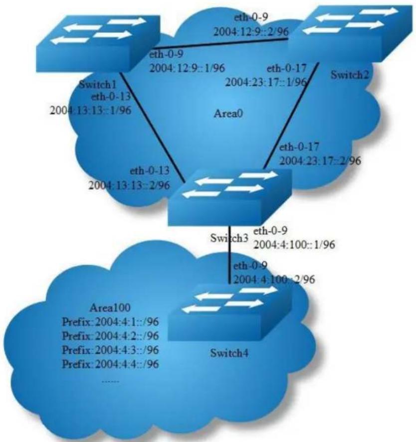
flowchart
graph TD
A["Switch1<br>eth-0-13<br>2004:13:13::1/96"] --> B["Area0"]
C["Switch2<br>eth-0-9<br>2004:12:9::2/96"] --> B
D["Switch3<br>eth-0-9<br>2004:4:100::1/96"] --> B
E["Switch4<br>eth-0-9<br>2004:4:100::2/96"] --> B
B --> F["Area100<br>Prefix: 2004:4:1::/96<br>Prefix: 2004:4:2::/96<br>Prefix: 2004:4:3::/96<br>Prefix: 2004:4:4::/96<br>......"]
Figure 13-4 OSPFv3 area
You can optionally configure several OSPFv3 area parameters. These parameters include authentication for password-based protection against unauthorized access to an area and stub areas. Stub areas are areas into which information on external routes is not sent. Instead, the area border router (ABR) generates a default external route into the stub area for destinations outside the autonomous system (AS).
Route summarization is the consolidation of advertised addresses into a single summary route to be advertised by other areas. If network numbers are contiguous, you can use the area range router configuration command to configure the ABR to advertise a summary route that covers all networks in the range.
The following configuration should be operated on all switches if the switch ID is not specified.
step 1 Enter the configure mode
Switch# configure terminal
step 2 Enable ipv6 globally
Switch(config)# ipv6 enable
step 3 Create OSPFv3 instance
Configuring Switch1:
Switch(config)# router ipv6 ospf 100
Switch(config-router)# router-id 1.1.1.1
Switch(config-router)# exit
Configuring Switch2:
Switch(config)# router ipv6 ospf 200
Switch(config-router)# router-id 2.2.2.2
Switch(config-router)# exit
Configuring Switch3:
Switch(config)# router ipv6 ospf 300
Switch(config-router)# router-id 3.3.3.3
Switch(config-router)# exit
Switch(config)# router ipv6 ospf 300
Switch(config-router)# area 100 range 2004:4::/32
Switch(config-router)# area 100 stub no-summary
Switch(config-router)# exit
Configuring Switch4:
Switch(config)# router ipv6 ospf 400
Switch(config-router)# router-id 4.4.4.4
Switch(config-router)# area 100 stub no-summary
Switch(config-router)# exit
step 4 Enter the interface configure mode and set the attributes of the interface
Interface configuration for Switch1:
Switch(config)# interface eth-0-9
Switch(config-if)# no switchport
Switch(config-if)# no shutdown
Switch(config-if)# ipv6 address 2004:12:9::1/96
Switch(config-if)# ipv6 router ospf 100 area 0 instance 0
Switch(config-if)# exit
Switch(config)#interface eth-0-13
Switch(config-if)#no switchport
Switch(config-if)#no shutdown
Switch(config-if)# ipv6 address 2004:13:13::2/96
Switch(config-if)# ipv6 router ospf 100 area 0 instance 0
Switch(config-if)# exit
Interface configuration for Switch2:
Switch(config)# interface eth-0-9
Switch(config-if)# no switchport
Switch(config-if)# no shutdown
Switch(config-if)# ipv6 address 2004:12:9::2/96
Switch(config-if)# ipv6 router ospf 200 area 0 instance 0
Switch(config-if)# exit
Switch(config)#interface eth-0-17
Switch(config-if)#no switchport
Switch(config-if)#no shutdown
Switch(config-if)# ipv6 address 2004:23:17::1/96
Switch(config-if)# ipv6 router ospf 200 area 0 instance 0
Switch(config-if)# exit
Interface configuration for Switch3:
Switch(config)# interface eth-0-9
Switch(config-if)# no switchport
Switch(config-if)# no shutdown
Switch(config-if)# ipv6 address 2004:4:100::1/96
Switch(config-if)# ipv6 router ospf 300 area 100 instance 0
Switch(config-if)# exit
Switch(config)# interface eth-0-13
Switch(config-if)# no switchport
Switch(config-if)# no shutdown
Switch(config-if)# ipv6 address 2004:13:13::2/96
Switch(config-if)# ipv6 router ospf 300 area 0 instance 0
Switch(config-if)# exit
Switch(config)# interface eth-0-17
Switch(config-if)# no switchport
Switch(config-if)# no shutdown
Switch(config-if)# ipv6 address 2004:23:17::2/96
Switch(config-if)# ipv6 router ospf 300 area 0 instance 0
Switch(config-if)# exit
Interface configuration for Switch4:
Switch(config)# interface eth-0-1
Switch(config-if)# no switchport
Switch(config-if)# no shutdown
Switch(config-if)# ipv6 address 2004:4:1::1/96
Switch(config-if)# ipv6 router ospf 400 area 100 instance 0
Switch(config-if)# exit
Switch(config)# interface eth-0-2
Switch(config-if)# no switchport
Switch(config-if)# no shutdown
Switch(config-if)# ipv6 address 2004:4:2::1/96
Switch(config-if)# ipv6 router ospf 400 area 100 instance 0
Switch(config-if)# exit
Switch(config)# interface eth-0-3
Switch(config-if)# no switchport
Switch(config-if)# no shutdown
Switch(config-if)# ipv6 address 2004:4:3::1/96
Switch(config-if)# ipv6 router ospf 400 area 100 instance 0
Switch(config-if)# exit
Switch(config)# interface eth-0-4
Switch(config-if)# no switchport
Switch(config-if)# no shutdown
Switch(config-if)# ipv6 address 2004:4:4::1/96
Switch(config-if)# ipv6 router ospf 400 area 100 instance 0
Switch(config-if)# exit
Switch(config)# interface eth-0-9
Switch(config-if)# no switchport
Switch(config-if)# no shutdown
Switch(config-if)# ipv6 address 2004:4:100::2/96
Switch(config-if)# ipv6 router ospf 400 area 100 instance 0
Switch(config-if)# exit
step 5 Exit the configure mode
Switch(config)# end
step 6 Validation
Display the result on Switch1:
Switch# show ipv6 route
IPv6 Routing Table
Codes: C - connected, S - static, R - RIP, I - IS-IS, B - BGP
O - OSPF, IA - OSPF inter area
N1 - OSPF NSSA external type 1, N2 - OSPF NSSA external type 2
E1 - OSPF external type 1, E2 - OSPF external type 2
Dr - DHCPV6 Relay
[*] - [AD/Metric]
Timers: Uptime
O IA 2004:4::/32 [110/3]
via fe80::c629:f2ff:fe02:3600, eth-0-13, 00:01:00
C 2004:12:9::/96
via ::, eth-0-9, 00:15:56
C 2004:12:9::1/128
via ::1, eth-0-9, 00:15:56
C 2004:13:13::/96
via ::, eth-0-13, 00:15:55
C 2004:13:13::2/128
via ::1, eth-0-13, 00:15:55
O 2004:23:17::/96 [110/2]
via fe80::bc22:aeff:fe64:aa00, eth-0-9, 00:08:10
via fe80::c629:f2ff:fe02:3600, eth-0-13, 00:08:10
C fe80::/10
via ::, Null0, 00:15:57
Display the result on Switch2:
Switch# show ipv6 route
IPv6 Routing Table
Codes: C - connected, S - static, R - RIP, I - IS-IS, B - BGP
O - OSPF, IA - OSPF inter area
N1 - OSPF NSSA external type 1, N2 - OSPF NSSA external type 2
E1 - OSPF external type 1, E2 - OSPF external type 2
Dr - DHCPV6 Relay
[*] - [AD/Metric]
Timers: Uptime
O IA 2004:4::/32 [110/3]
via fe80::c629:f2ff:fe02:3600, eth-0-17, 00:00:57
C 2004:12:9::/96
via ::, eth-0-9, 00:12:24
C 2004:12:9::2/128
via ::1, eth-0-9, 00:12:24
O 2004:13:13::/96 [110/2]
via fe80::b242:55ff:fe05:ff00, eth-0-9, 00:07:52
via fe80::c629:f2ff:fe02:3600, eth-0-17, 00:07:52
C 2004:23:17::/96
via ::, eth-0-17, 00:12:24
C 2004:23:17::1/128
via ::1, eth-0-17, 00:12:24
C fe80::/10
via ::, Null0, 00:12:26
Display the result on Switch3:
Switch# show ipv6 route
IPv6 Routing Table
Codes: C - connected, S - static, R - RIP, I - IS-IS, B - BGP
O - OSPF, IA - OSPF inter area
N1 - OSPF NSSA external type 1, N2 - OSPF NSSA external type 2
E1 - OSPF external type 1, E2 - OSPF external type 2
Dr - DHCPV6 Relay
[*] - [AD/Metric]
Timers: Uptime
O 2004:4::/32 [110/0]
via ::, Null0, 00:08:31
O 2004:4:1::/96 [110/2]
via fe80::ee66:91ff:fe45:db00, eth-0-9, 00:01:08
O 2004:4:2::/96 [110/2]
via fe80::ee66:91ff:fe45:db00, eth-0-9, 00:01:08
O 2004:4:3::/96 [110/2]
via fe80::ee66:91ff:fe45:db00, eth-0-9, 00:01:08
O 2004:4:4::/96 [110/2]
via fe80::ee66:91ff:fe45:db00, eth-0-9, 00:01:08
C 2004:4:100::/96
via ::, eth-0-9, 00:08:32
C 2004:4:100::1/128
via ::1, eth-0-9, 00:08:32
O 2004:12:9::/96 [110/2]
via fe80::b242:55ff:fe05:ff00, eth-0-13, 00:08:03
via fe80::bc22:aeff:fe64:aa00, eth-0-17, 00:08:03
O 2004:13:13::/96 [110/1]
via fe80::b242:55ff:fe05:ff00, eth-0-13, 00:08:18
C 2004:23:17::/96
via ::, eth-0-17, 00:08:32
C 2004:23:17::2/128
via ::1, eth-0-17, 00:08:32
C fe80::/10
via ::, Null0, 00:08:34
Display the result on Switch4:
Switch# show ipv6 route
IPv6 Routing Table
Codes: C - connected, S - static, R - RIP, I - IS-IS, B - BGP
O - OSPF, IA - OSPF inter area
N1 - OSPF NSSA external type 1, N2 - OSPF NSSA external type 2
E1 - OSPF external type 1, E2 - OSPF external type 2
Dr - DHCPV6 Relay
[*] - [AD/Metric]
Timers: Uptime
O IA ::/0 [110/2]
via fe80::c629:f2ff:fe02:3600, eth-0-9, 00:00:53
C 2004:4:1::/96
via ::, eth-0-1, 00:03:09
C 2004:4:1::1/128
via ::1, eth-0-1, 00:03:09
C 2004:4:2::/96
via ::, eth-0-2, 00:03:08
C 2004:4:2::1/128
via ::1, eth-0-2, 00:03:08
C 2004:4:3::/96
via ::, eth-0-3, 00:03:08
C 2004:4:3::1/128
via ::1, eth-0-3, 00:03:08
C 2004:4:4::/96
via ::, eth-0-4, 00:03:09
C 2004:4:4::1/128
via ::1, eth-0-4, 00:03:09
C 2004:4:100::/96
via ::, eth-0-9, 00:03:09
C 2004:4:100::2/128
via ::1, eth-0-9, 00:03:09
C fe80::/10
via ::, Null0, 00:03:10
Redistributing Routes into OSPFv3
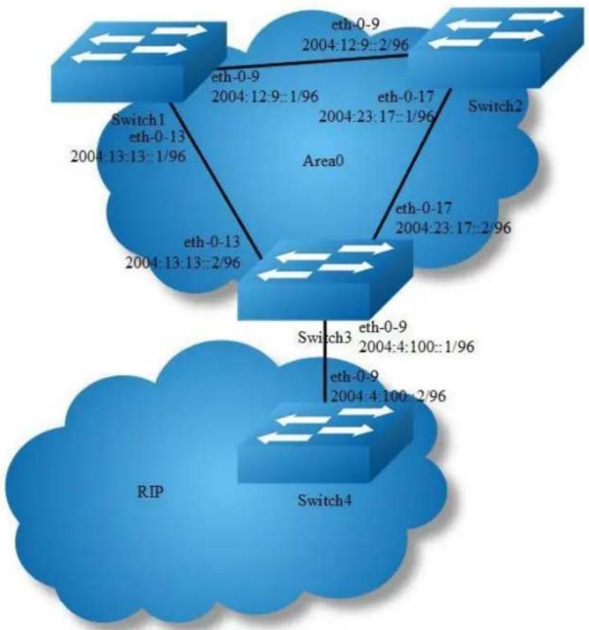
flowchart
graph TD
A["Switch1 eth-0-13 2004:13:13::1/96"] --> B["Area0"]
C["Switch2"] --> D["eth-0-9 2004:12:9::2/96"]
E["Switch3"] --> F["eth-0-9 2004:4:100::1/96"]
G["RIP"] --> H["eth-0-9 2004:4:100::2/96"]
I["Switch4"] --> J["eth-0-17 2004:23:17::2/96"]
Figure 13-5 OSPFv3 Redistribute
In this example the configuration causes RIPng routes to be imported into the OSPFv3 routing table and advertised as Type 5 External LSAs into Area 0.
The following configuration should be operated on all switches if the switch ID is not specified.
step 1 Enter the configure mode
Switch# configure terminal
step 2 Enable ipv6 globally
Switch(config)# ipv6 enable
step 3 Create OSPFv3 instance
Configuring Switch1:
Switch(config)# router ipv6 ospf 100
Switch(config-router)# router-id 1.1.1.1
Switch(config-router)# exit
Configuring Switch2:
Switch(config)# router ipv6 ospf 200
Switch(config-router)# router-id 2.2.2.2
Switch(config-router)# exit
Configuring Switch3:
Switch(config)# router ipv6 ospf 300
Switch(config-router)# router-id 3.3.3.3
Switch(config-router)# redistribute ripng
Switch(config-router)# exit
step 4 Create RIPng instance
Configuring Switch3:
Switch(config)# router ipv6 rip
Switch(config-router)# exit
Configuring Switch4:
Switch(config)# router ipv6 rip
Switch(config-router)# exit
step 5 Enter the interface configure mode and set the attributes of the interface
Interface configuration for Switch1:
Switch(config)# interface eth-0-9
Switch(config-if)# no switchport
Switch(config-if)# no shutdown
Switch(config-if)# ipv6 address 2004:12:9::1/96
Switch(config-if)# ipv6 router ospf 100 area 0 instance 0
Switch(config-if)# exit
Switch(config)#interface eth-0-13
Switch(config-if)# no switchport
Switch(config-if)# no shutdown
Switch(config-if)# ipv6 address 2004:13:13::2/96
Switch(config-if)# ipv6 router ospf 100 area 0 instance 0
Switch(config-if)# exit
Interface configuration for Switch2:
Switch(config)# interface eth-0-9
Switch(config-if)# no switchport
Switch(config-if)# no shutdown
Switch(config-if)# ipv6 address 2004:12:9::2/96
Switch(config-if)# ipv6 router ospf 200 area 0 instance 0
Switch(config-if)# exit
Switch(config)#interface eth-0-17
Switch(config-if)#no switchport
Switch(config-if)#no shutdown
Switch(config-if)# ipv6 address 2004:23:17::1/96
Switch(config-if)# ipv6 router ospf 200 area 0 instance 0
Switch(config-if)# exit
Interface configuration for Switch3:
Switch(config)# interface eth-0-9
Switch(config-if)# no switchport
Switch(config-if)# no shutdown
Switch(config-if)# ipv6 address 2004:4:100::1/96
Switch(config-if)# ipv6 router rip
Switch(config-if)# exit
Switch(config)# interface eth-0-13
Switch(config-if)# no switchport
Switch(config-if)# no shutdown
Switch(config-if)# ipv6 address 2004:13:13::2/96
Switch(config-if)# ipv6 router ospf 300 area 0 instance 0
Switch(config-if)# exit
Switch(config)# interface eth-0-17
Switch(config-if)# no switchport
Switch(config-if)# no shutdown
Switch(config-if)# ipv6 address 2004:23:17::2/96
Switch(config-if)# ipv6 router ospf 300 area 0 instance 0
Switch(config-if)# exit
Interface configuration for Switch4:
Switch(config)# interface eth-0-1
Switch(config-if)# no switchport
Switch(config-if)# no shutdown
Switch(config-if)# ipv6 address 2004:4:1::1/96
Switch(config-if)# ipv6 router rip
Switch(config-if)# exit
Switch(config)# interface eth-0-9
Switch(config-if)# no switchport
Switch(config-if)# no shutdown
Switch(config-if)# ipv6 address 2004:4:100::2/96
Switch(config-if)# ipv6 router rip
Switch(config-if)# exit
step 6 Exit the configure mode
Switch(config)# end
step 7 Validation
Display the result on Switch1:
Switch# show ipv6 route
IPv6 Routing Table
Codes: C - connected, S - static, R - RIP, I - IS-IS, B - BGP
O - OSPF, IA - OSPF inter area
N1 - OSPF NSSA external type 1, N2 - OSPF NSSA external type 2
E1 - OSPF external type 1, E2 - OSPF external type 2
Dr - DHCPV6 Relay
[*] - [AD/Metric]
Timers: Uptime
O E2 2004:4:1::/96 [110/20]
via fe80::c629:f2ff:fe02:3600, eth-0-13, 00:00:03
C 2004:12:9::/96
via ::, eth-0-9, 00:34:20
C 2004:12:9::1/128
via ::1, eth-0-9, 00:34:20
C 2004:13:13::/96
via ::, eth-0-13, 00:34:19
C 2004:13:13::2/128
via ::1, eth-0-13, 00:34:19
O 2004:23:17::/96 [110/2]
via fe80::bc22:aeff:fe64:aa00, eth-0-9, 00:26:34
via fe80::c629:f2ff:fe02:3600, eth-0-13, 00:26:34
C fe80::/10
via ::, Null0, 00:34:21
Switch# show ipv6 ospf database external
OSPFv3 Router with ID (1.1.1.1) (Process 100)
AS-external-LSA
LS age: 140
LS Type: AS-External-LSA
Link State ID: 0.0.0.1
Advertising Router: 3.3.3.3
LS Seq Number: 0x80000001
Checksum: 0x66F7
Length: 44
Metric Type: 2 (Larger than any link state path)
Metric: 20
Prefix: 2004:4:1::/96
Prefix Options: 0 (-|-|-|-)
External Route Tag: 0
Display the result on Switch2:
Switch# show ipv6 route
IPv6 Routing Table
Codes: C - connected, S - static, R - RIP, I - IS-IS, B - BGP
O - OSPF, IA - OSPF inter area
N1 - OSPF NSSA external type 1, N2 - OSPF NSSA external type 2
E1 - OSPF external type 1, E2 - OSPF external type 2
Dr - DHCPV6 Relay
[*] - [AD/Metric]
Timers: Uptime
O E2 2004:4:1::/96 [110/20]
via fe80::c629:f2ff:fe02:3600, eth-0-17, 00:02:43
C 2004:12:9::/96
via ::, eth-0-9, 00:33:31
C 2004:12:9::2/128
via ::1, eth-0-9, 00:33:31
O 2004:13:13::/96 [110/2]
via fe80::b242:55ff:fe05:ff00, eth-0-9, 00:28:59
via fe80::c629:f2ff:fe02:3600, eth-0-17, 00:28:59
C 2004:23:17::/96
via ::, eth-0-17, 00:33:31
C 2004:23:17::1/128
via ::1, eth-0-17, 00:33:31
C fe80::/10
via ::, Null0, 00:33:33
Switch# show ipv6 ospf database external
show ipv6 ospf database external
OSPFv3 Router with ID (2.2.2.2) (Process 200)
AS-external-LSA
LS age: 195
LS Type: AS-External-LSA
Link State ID: 0.0.0.1
Advertising Router: 3.3.3.3
LS Seq Number: 0x80000001
Checksum: 0x66F7
Length: 44
Metric Type: 2 (Larger than any link state path)
Metric: 20
Prefix: 2004:4:1::/96
Prefix Options: 0 (-|-|-|)-)
External Route Tag: 0
Display the result on Switch3:
Switch# show ipv6 route
IPv6 Routing Table
Codes: C - connected, S - static, R - RIP, I - IS-IS, B - BGP
O - OSPF, IA - OSPF inter area
N1 - OSPF NSSA external type 1, N2 - OSPF NSSA external type 2
E1 - OSPF external type 1, E2 - OSPF external type 2
Dr - DHCPV6 Relay
[*] - [AD/Metric]
Timers: Uptime
R 2004:4:1::/96 [120/2]
via fe80::ee66:91ff:fe45:db00, eth-0-9, 00:03:43
C 2004:4:100::/96
via ::, eth-0-9, 00:07:01
C 2004:4:100::1/128
via ::1, eth-0-9, 00:07:01
2004:12:9::/96 [110/2]
via fe80::b242:55ff:fe05:ff00, eth-0-13, 00:29:57
via fe80::bc22:aeff:fe64:aa00, eth-0-17, 00:29:57
2004:13:13::/96 [110/1]
via fe80::b242:55ff:fe05:ff00, eth-0-13, 00:30:12
2004:23:17::/96
via ::, eth-0-17, 00:30:26
2004:23:17::2/128
via ::1, eth-0-17, 00:30:26
fe80::/10
via ::, Null0, 00:30:28
Switch# show ipv6 ospf database external
show ipv6 ospf database external
OSPFv3 Router with ID (3.3.3.3) (Process 300)
AS-external-LSA
LS age: 250
LS Type: AS-External-LSA
Link State ID: 0.0.0.1
Advertising Router: 3.3.3.3
LS Seq Number: 0x80000001
Checksum: 0x66F7
Length: 44
Metric Type: 2 (Larger than any link state path)
Metric: 20
Prefix: 2004:4:1::/96
Prefix Options: 0 (-||-|-|--)
External Route Tag: 0
Display the result on Switch4:
Switch# show ipv6 route
IPv6 Routing Table
Codes: C - connected, S - static, R - RIP, I - IS-IS, B - BGP
O - OSPF, IA - OSPF inter area
N1 - OSPF NSSA external type 1, N2 - OSPF NSSA external type 2
E1 - OSPF external type 1, E2 - OSPF external type 2
Dr - DHCPV6 Relay
[*] - [AD/Metric]
Timers: Uptime
C 2004:4:1::/96
via ::, eth-0-1, 00:04:48
C 2004:4:1::1/128
via ::1, eth-0-1, 00:04:48
C 2004:4:100::/96
via ::, eth-0-9, 00:06:59
C 2004:4:100::2/128
via ::1, eth-0-9, 00:06:59
C fc80::/10
via ::, Null0, 00:07:00
Configure OSPFv3 Cost
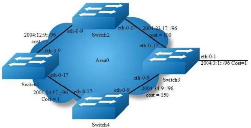
flowchart
graph TD
A["Switch1"] -->|2004:14:17:96 Cost=1| B["Area0"]
C["Switch2"] -->|2004:23:17:96 cost=100| B
D["Switch3"] -->|2004:34:9:96 cost=150| B
E["Switch4"] -->|2004:12:9:96 cost=1| B
B --> F["eth-0-9"]
B --> G["eth-0-17"]
B --> H["eth-0-9"]
B --> I["eth-0-9"]
B --> J["eth-0-9"]
style B fill:#888,stroke:#333,stroke-width:2px
note right of B Area0
eth-0-1
2004:3:1::/96 Cost=1
end
Figure 13-6 OSPFv3 Cost
You can make a route the preferred route by changing its cost. In this example, cost has been configured to make Switch2 the next hop for Switch1.
The default cost on each interface is 1(1000M speed). Interface eth2 on Switch2 has a cost of 100 and interface eth2 on Switch3 has a cost of 150. The total cost to reach(Switch4 network 10.10.14.0) through Switch2 and Switch3:
Switch2: 1+1+100 = 102 Switch3: 1+1+150 = 152
Therefore, Switch1 chooses Switch2 as its next hop for destination Switch4
step 1 Enter the configure mode
Switch# configure terminal
step 2 Enable ipv6 globally
Switch(config)# ipv6 enable
step 3 Create OSPFv3 instance
Configuring Switch1:
Switch(config)# router ipv6 ospf 100
Switch(config-router)# router-id 1.1.1.1
Switch(config-router)# exit
Configuring Switch2:
Switch(config)# router ipv6 ospf 200
Switch(config-router)# router-id 2.2.2.2
Switch(config-router)# exit
Configuring Switch3:
Switch(config)# router ipv6 ospf 300
Switch(config-router)# router-id 3.3.3.3
Switch(config-router)# exit
Configuring Switch4:
Switch(config)# router ipv6 ospf 400
Switch(config-router)# router-id 4.4.4.4
Switch(config-router)# exit
step 4 Enter the interface configure mode and set the attributes of the interface
Interface configuration for Switch1:
Switch(config)# interface eth-0-9
Switch(config-if)# no switchport
Switch(config-if)# no shutdown
Switch(config-if)# ipv6 address 2004:12:9::1/96
Switch(config-if)# ipv6 router ospf 100 area 0 instance 0
Switch(config-if)# exit
Switch(config)#interface eth-0-17
Switch(config-if)#no switchport
Switch(config-if)#no shutdown
Switch(config-if)# ipv6 address 2004:14:17::1/96
Switch(config-if)# ipv6 router ospf 100 area 0 instance 0
Switch(config-if)# exit
Interface configuration for Switch2:
Switch(config)# interface eth-0-9
Switch(config-if)# no switchport
Switch(config-if)# no shutdown
Switch(config-if)# ipv6 address 2004:12:9::2/96
Switch(config-if)# ipv6 router ospf 200 area 0 instance 0
Switch(config-if)# exit
Switch(config)#interface eth-0-17
Switch(config-if)#no switchport
Switch(config-if)#no shutdown
Switch(config-if)# ipv6 address 2004:23:17::1/96
Switch(config-if)# ipv6 router ospf 200 area 0 instance 0
Switch(config-if)# ipv6 ospf cost 100
Switch(config-if)# exit
Interface configuration for Switch3:
Switch(config)# interface eth-0-1
Switch(config-if)# no switchport
Switch(config-if)# no shutdown
Switch(config-if)# ipv6 address 2004:3:1::1/96
Switch(config-if)# ipv6 router ospf 300 area 0 instance 0
Switch(config-if)# exit
Switch(config)# interface eth-0-9
Switch(config-if)# no switchport
Switch(config-if)# no shutdown
Switch(config-if)# ipv6 address 2004:34:9::1/96
Switch(config-if)# ipv6 router ospf 300 area 0 instance 0
Switch(config-if)# exit
Switch(config)# interface eth-0-17
Switch(config-if)# no switchport
Switch(config-if)# no shutdown
Switch(config-if)# ipv6 address 2004:23:17::2/96
Switch(config-if)# ipv6 router ospf 300 area 0 instance 0
Switch(config-if)# exit
Interface configuration for Switch4:
Switch(config)# interface eth-0-9
Switch(config-if)# no switchport
Switch(config-if)# no shutdown
Switch(config-if)# ipv6 address 2004:34:9::2/96
Switch(config-if)# ipv6 router ospf 400 area 0 instance 0
Switch(config-if)# ipv6 ospf cost 150
Switch(config-if)# exit
Switch(config)# interface eth-0-17
Switch(config-if)# no switchport
Switch(config-if)# no shutdown
Switch(config-if)# ipv6 address 2004:14:17::2/96
Switch(config-if)# ipv6 router ospf 400 area 0 instance 0
Switch(config-if)# end
step 5 Exit the configure mode
Switch(config)# end
step 6 Validation
Display the result on Switch1:
Switch# show ipv6 ospf route
IPv6 Routing Table
Codes: C - connected, S - static, R - RIP, I - IS-IS, B - BGP
O - OSPF, IA - OSPF inter area
N1 - OSPF NSSA external type 1, N2 - OSPF NSSA external type 2
E1 - OSPF external type 1, E2 - OSPF external type 2
Dr - DHCPV6 Relay
[*] - [AD/Metric]
Timers: Uptime
O 2004:3:1::/96 [110/102]
via fe80::bc22:aeff:fe64:aa00, eth-0-9, 00:08:06
C 2004:12:9::/96
via ::, eth-0-9, 01:15:43
C 2004:12:9::1/128
via ::1, eth-0-9, 01:15:43
C 2004:14:17::/96
via ::, eth-0-17, 00:18:38
C 2004:14:17::1/128
via ::1, eth-0-17, 00:18:38
O 2004:23:17::/96 [110/101]
via fe80::bc22:aeff:fe64:aa00, eth-0-9, 00:08:06
O 2004:34:9::/96 [110/102]
via fe80::bc22:aeff:fe64:aa00, eth-0-9, 00:03:56
C fe80::/10
via ::, Null0, 01:15:44
Display the result on Switch2:
Switch# show ipv6 ospf route
IPv6 Routing Table
Codes: C - connected, S - static, R - RIP, I - IS-IS, B - BGP
O - OSPF, IA - OSPF inter area
N1 - OSPF NSSA external type 1, N2 - OSPF NSSA external type 2
E1 - OSPF external type 1, E2 - OSPF external type 2
Dr - DHCPV6 Relay
[*] - [AD/Metric]
Timers: Uptime
O 2004:3:1::/96 [110/101]
via fe80::c629:f2ff:fe02:3600, eth-0-17, 00:08:33
C 2004:12:9::/96
via ::, eth-0-9, 01:12:40
C 2004:12:9::2/128
via ::1, eth-0-9, 01:12:40
O 2004:14:17::/96 [110/2]
via fe80::b242:55ff:fe05:ff00, eth-0-9, 00:18:43
C 2004:23:17::/96
via ::, eth-0-17, 01:12:40
C 2004:23:17::1/128
via ::1, eth-0-17, 01:12:40
O 2004:34:9::/96 [110/101]
via fe80::c629:f2ff:fe02:3600, eth-0-17, 00:04:23
C fe80::/10
via ::, Null0, 01:12:42
Display the result on Switch3:
Switch# show ipv6 ospf route
IPv6 Routing Table
Codes: C - connected, S - static, R - RIP, I - IS-IS, B - BGP
O - OSPF, IA - OSPF inter area
N1 - OSPF NSSA external type 1, N2 - OSPF NSSA external type 2
E1 - OSPF external type 1, E2 - OSPF external type 2
Dr - DHCPV6 Relay
[*] - [AD/Metric]
Timers: Uptime
C 2004:3:1::/96
via ::, eth-0-1, 00:13:54
C 2004:3:1::1/128
via ::1, eth-0-1, 00:13:54
O 2004:12:9::/96 [110/2]
via fe80::bc22:aeff:fe64:aa00, eth-0-17, 00:19:47
O 2004:14:17::/96 [110/2]
via fe80::ee66:91ff:fe45:db00, eth-0-9, 00:02:27
C 2004:23:17::/96
via ::, eth-0-17, 01:09:02
C 2004:23:17::2/128
via ::1, eth-0-17, 01:09:02
C 2004:34:9::/96
via ::, eth-0-9, 00:04:52
C 2004:34:9::1/128
via ::1, eth-0-9, 00:04:52
C fe80::/10
via ::, Null0, 01:09:04
Display the result on Switch4:
Switch# show ipv6 route
IPv6 Routing Table
Codes: C - connected, S - static, R - RIP, I - IS-IS, B - BGP
O - OSPF, IA - OSPF inter area
N1 - OSPF NSSA external type 1, N2 - OSPF NSSA external type 2
E1 - OSPF external type 1, E2 - OSPF external type 2
Dr - DHCPV6 Relay
[*] - [AD/Metric]
Timers: Uptime
O 2004:3:1::/96 [110/103]
via fe80::b242:55ff:fe05:ff00, eth-0-17, 00:02:35
O 2004:12:9::/96 [110/2]
via fe80::b242:55ff:fe05:ff00, eth-0-17, 00:02:35
C 2004:14:17::/96
via ::, eth-0-17, 00:04:09
C 2004:14:17::2/128
via ::1, eth-0-17, 00:04:09
O 2004:23:17::/96 [110/102]
via fe80::b242:55ff:fe05:ff00, eth-0-17, 00:02:35
C 2004:34:9::/96
via ::, eth-0-9, 00:06:06
C 2004:34:9::2/128
via ::1, eth-0-9, 00:06:06
C fe80::/10
via ::, Null0, 00:44:59
Monitoring OSPFv3
You can display specific statistics such as the contents of IPv6 routing tables, caches, and databases.
Display general information about OSPFv3 routing processes
Switch# show ipv6 ospf
Routing Process "OSPFv3 (300)" with ID 3.3.3.3
Process uptime is 3 hours 23 minutes
SPF schedule delay min 0.500 secs, SPF schedule delay max 50.0 secs
Minimum LSA interval 5 secs, Minimum LSA arrival 1 secs
Number of incoming current DD exchange neighbors 0/5
Number of outgoing current DD exchange neighbors 0/5
Number of external LSA 0. Checksum Sum 0x0000
Number of AS-Scoped Unknown LSA 0
Number of LSA originated 6
Number of LSA received 43
Number of areas in this router is 1
Area BACKBONE(0)
Number of interfaces in this area is 1(1)
SPF algorithm executed 14 times
Number of LSA 5. Checksum Sum 0x30DCD
Number of Unknown LSA 0
Display lists of information related to the OSPFv3 database
Switch# show ipv6 ospf database database-summary
OSPFv3 Router with ID (3.3.3.3) (Process ID 300)
Area (0.0.0.0) database summary
LSA Type Count MaxAge
Router 3 0
Network 1 0
Inter-Prefix 0 0
Inter-Router 0 0
Intra-Prefix 1 0
Subtotal 5 0
Process 300 database summary
LSA Type Count MaxAge
Router 3 0
Network 1 0
Inter-Prefix 0 0
Inter-Router 0 0
Type-5 Ext 0 0
Link 3 0
Intra-Prefix 1 0
Total 8 0
Switch# show ipv6 ospf database router
OSPFv3 Router with ID (3.3.3.3) (Process 300)
Router-LSA (Area 0.0.0.0)
LS age: 600
LS Type: Router-LSA
Link State ID: 0.0.0.0
Advertising Router: 1.1.1.1
LS Seq Number: 0x80000008
Checksum: 0x9A57
Length: 40
Flags: 0x00 (-|-|-|-|-)
Options: 0x000013 (-|R|-|-|E|V6)
Link connected to: a Transit Network
Metric: 1
Interface ID: 9
Neighbor Interface ID: 13
Neighbor Router ID: 3.3.3.3
LS age: 597
LS Type: Router-LSA
Link State ID: 0.0.0.0
Advertising Router: 2.2.2.2
LS Seq Number: 0x8000000D
Checksum: 0xE2FD
Length: 40
Flags: 0x00 (-|-|-|-|-)
Options: 0x000013 (-|R|-|-|E|V6)
Link connected to: a Transit Network
Metric: 1
Interface ID: 17
Neighbor Interface ID: 13
Neighbor Router ID: 3.3.3.3
LS age: 599
LS Type: Router-LSA
Link State ID: 0.0.0.0
Advertising Router: 3.3.3.3
LS Seq Number: 0x8000000C
Length: 40
Flags: 0x00 (-|-|-|-|-)
Options: 0x000013 (-|R|-|-|E|V6)
Link connected to: a Transit Network
Metric: 1
Interface ID: 13
Neighbor Interface ID: 13
Neighbor Router ID: 3.3.3.3
Switch# show ipv6 ospf database network self-originate
OSPFv3 Router with ID (3.3.3.3) (Process 300)
Network-LSA (Area 0.0.0.0)
LS age: 1261
LS Type: Network-LSA
Link State ID: 0.0.0.13
Advertising Router: 3.3.3.3
LS Seq Number: 0x80000004
Checksum: 0x727E
Length: 36
Options: 0x000013 (-|R|-|-|E|V6)
Attached Router: 3.3.3.3
Attached Router: 1.1.1.1
Attached Router: 2.2.2.2
Switch# show ipv6 ospf database inter-router
OSPFv3 Router with ID (3.3.3.3) (Process 300)
Switch# show ipv6 ospf database intra-prefix
OSPFv3 Router with ID (3.3.3.3) (Process 300)
Intra-Area-Prefix-LSA (Area 0.0.0.0)
LS age: 1623
LS Type: Intra-Area-Prefix-LSA
Link State ID: 0.0.0.2
Advertising Router: 3.3.3.3
LS Seq Number: 0x80000004
Checksum: 0x8FA8
Length: 48
Number of Prefixes: 1
Referenced LS Type: 0x2002
Referenced Link State ID: 0.0.0.13
Referenced Advertising Router: 3.3.3.3
Prefix: 2004:12:9::/96
Prefix Options: 0 (-|-|-|-)
Metric: 0
Switch# show ipv6 ospf database inter-prefix
OSPFv3 Router with ID (3.3.3.3) (Process 300)
Switch# show ipv6 ospf database link
OSPFv3 Router with ID (3.3.3.3) (Process 300)
Link-LSA (Interface eth-0-13)
LS age: 641
LS Type: Link-LSA
Link State ID: 0.0.0.9
Advertising Router: 1.1.1.1
LS Seq Number: 0x80000005
Checksum: 0x9C1C
Length: 60
Priority: 1
Options: 0x000013 (-|R|-|-|E|V6)
Link-Local Address: fe80::20e6:7eff:fee2:d400
Number of Prefixes: 1
Prefix: 2004:12:9::/96
Prefix Options: 0 (-|-|-|-)
LS age: 698
LS Type: Link-LSA
Link State ID: 0.0.0.17
Advertising Router: 2.2.2.2
LS Seq Number: 0x80000008
Checksum: 0x2159
Length: 60
Priority: 1
Options: 0x000013 (-|R|-|-|E|V6)
Link-Local Address: fe80::fcc8:7bff:fe3e:ec00
Number of Prefixes: 1
Prefix: 2004:12:9::/96
Prefix Options: 0 (-|-|-|-)
LS age: 1535
LS Type: Link-LSA
Link State ID: 0.0.0.13
Advertising Router: 3.3.3.3
LS Seq Number: 0x80000008
Checksum: 0x6E9A
Length: 60
Priority: 10
Options: 0x000013 (-|R|-|-|E|V6)
Link-Local Address: fe80::ba5d:79ff:fe55:ed00
Number of Prefixes: 1
Prefix: 2004:12:9::/96
Prefix Options: 0 (-|-|-|-)
Switch# show ipv6 ospf database external
OSPFv3 Router with ID (3.3.3.3) (Process 300)
Display OSPFv3-related interface information
Switch# show ipv6 ospf interface
eth-0-13 is up, line protocol is up
Interface ID 13
IPv6 Prefixes
fe80::ba5d:79ff:fe55:ed00/10 (Link-Local Address)
2004:12:9::3/96
OSPFv3 Process (300), Area 0.0.0.0, Instance ID 0
Router ID 3.3.3.3, Network Type BROADCAST, Cost: 1
Transmit Delay is 1 sec, State DR, Priority 10
Designated Router (ID) 3.3.3.3
Interface Address fe80::ba5d:79ff:fe55:ed00
Backup Designated Router (ID) 2.2.2.2
Interface Address fe80::fcc8:7bff:fe3e:ec00
Timer interval configured, Hello 10, Dead 40, Wait 40, Retransmit 5
Hello due in 00:00:01
Neighbor Count is 2, Adjacent neighbor count is 2
Display OSPFv3 interface neighbor information
Switch# show ipv6 ospf neighbor
OSPFv3 Process (300)
Neighbor ID Pri State Dead Time Interface Instance ID
1.1.1.1 1 Full/DROther 00:00:39 eth-0-13 0
2.2.2.2 1 Full/Backup 00:00:33 eth-0-13 0
13.2.3 Application cases
N/A
13.3 Configuring RIPng
13.3.1 Overview
Function Introduction
Routing Information Protocol Next Generation (RIPng) is an IPv6 route exchange protocol that uses a distance vector (a number representing distance) to measure the cost of a given route. The cost is a distance vector because the cost is often equivalent to the number of router hops between the source and the destination networks. RIPng can receive multiple paths to a destination. The system evaluates the paths, selects the best path, and saves the path in the IPv6 route table as the route to the destination.
Typically, the best path is the path with the fewest hops. A hop is another router through which packets must travel to reach the destination. If RIPng receives a RIPng update from another router that contains a path with fewer hops than the path stored in the route table, the system replaces the older route with the newer one.
The system then includes the new path in the updates it sends to other RIPng
routers. RIPng routers also can modify a route's cost, generally by adding to it, to bias the selection of a route for a given destination. In this case, the actual number of router hops may be the same, but the route has an administratively higher cost and is thus less likely to be used than other, lower-cost routes. A RIPng route can have a maximum cost of 15. Any destination with a higher cost is considered unreachable. Although limiting to larger networks, the low maximum hop count prevents endless loops in the network.
This chapter contains basic RIPng configuration examples. To see details on the commands used in these examples, or to see the outputs of the Validation commands, refer to the RIPng Command Reference. To avoid repetition, some Common commands, like configure terminal, have not been listed under the Commands Used section.
There are some differences between RIPng and RIP:
UDP port number: RIPng uses UDP port number 521 to send or receive package.
Multicast address: RIPng uses FF02::9 to multicast package to other routers of link local.
Nexthop address: RIPng uses 128 bit ipv6 address.
Source address: RIPng uses IPv6 link-local address FE80::/10 to be the source address when updating package to neighbor.
Principle Description
The RIPng module is based on the following RFC: RFC 2080 - RIPng for IPv6
13.3.2 Configuration
Enabling RIPng

flowchart
graph LR
A["eth-0-48\n2001:db8:48::2/64"] --> B["Switch1"]
B --> C["eth-0-12\n2001:db8:12::/64"]
C --> D["eth-0-12\n2001:ab8:48::2/64"]
D --> E["eth-0-48\n2001:ab8:48::2/64"]
Figure 13-7 RIPng
This example shows how to enable RIPng protocols on two switches:
The following configuration should be operated on all switches if the switch ID is not specified.
step 1 Enter the configure mode
Switch# configure terminal
step 2 Enable ipv6 globally
Switch(config)# ipv6 enable
step 3 Enter the interface configure mode and set the attributes of the interface
Interface configuration for Switch1:
Switch(config)# interface eth-0-12
Switch(config-if)# no switchport
Switch(config-if)# no shutdown
Switch(config-if)# ipv6 address 2001:db8:12::1/64
Switch(config-if)# ipv6 router rip
Switch(config-if)# exit
Switch(config)# interface eth-0-48
Switch(config-if)# no switchport
Switch(config-if)# no shutdown
Switch(config-if)# ipv6 address 2001:db8:48::2/64
Switch(config-if)# ipv6 router rip
Switch(config-if)# exit
Interface configuration for Switch2:
Switch(config)# interface eth-0-12
Switch(config-if)# no switchport
Switch(config-if)# no shutdown
Switch(config-if)# ipv6 address 2001:db8:12::2/64
Switch(config-if)# ipv6 router rip
Switch(config-if)# exit
Switch(config)# interface eth-0-48
Switch(config-if)# no switchport
Switch(config-if)# no shutdown
Switch(config-if)# ipv6 address 2001:ab8:49::2/64
Switch(config-if)# ipv6 router rip
Switch(config-if)# exit
step 4 Exit the configure mode
Switch(config)# end
step 5 Validation
Display the result on Switch1:
Switch# show ipv6 rip database
Codes: R - RIP, Rc - RIP connected, Rs - RIP static, Ra - RIP aggregated,
Rcx - RIP connect suppressed, Rsx - RIP static suppressed,
K - Kernel, C - Connected, S - Static, O - OSPF, I - IS-IS, B - BGP
Network Next Hop If Met Tag Time
R 2001:ab8:49::/64 fe80::1271:dlff:fec8:3300 eth-0-12 5 0 00:02:34
Rc 2001:db8:12::/64 :: eth-0-12 1 0
Rc 2001:db8:48::/64 :: eth-0-48 1 0
Switch# show ipv6 rip interface
eth-0-12 is up, line protocol is up
Routing Protocol: RIPng
Passive interface: Disabled
Split horizon: Enabled with Poisoned Reversed
IPv6 interface address:
2001:db8:12::1/64
fe80::7e14:63ff:fe76:8900/10
eth-0-48 is up, line protocol is up
Routing Protocol: RIPng
Passive interface: Disabled
Split horizon: Enabled with Poisoned Reversed
IPv6 interface address:
2001:db8:48::2/64
fe80::7e14:63ff:fe76:8900/10
Switch# show ipv6 protocols rip
Routing Protocol is "ripng"
Sending updates every 30 seconds with +/-5 seconds, next due in 7 seconds
Timeout after 180 seconds, garbage collect after 120 seconds
Outgoing update filter list for all interface is not set
Incoming update filter list for all interface is not set
Default redistribute metric is 1
Redistributing:
Interface
eth-0-12
eth-0-48
Routing for Networks:
Number of routes (including connected): 3
Distance: (default is 120)
Switch# show ipv6 route rip
IPv6 Routing Table
Codes: C - connected, S - static, R - RIP, I - IS-IS, B - BGP
O - OSPF, IA - OSPF inter area
N1 - OSPF NSSA external type 1, N2 - OSPF NSSA external type 2
E1 - OSPF external type 1, E2 - OSPF external type 2
Dr - DHCPV6 Relay
[*] - [AD/Metric]
Timers: Uptime
R 2001:ab8:49::/64 [120/5]
via fe80::1271:dlff:fec8:3300, eth-0-12, 00:26:05
Display the result on Switch2:
Switch# show ipv6 rip database
Codes: R - RIP, Rc - RIP connected, Rs - RIP static, Ra - RIP aggregated,
Rcx - RIP connect suppressed, Rsx - RIP static suppressed,
K - Kernel, C - Connected, S - Static, O - OSPF, I - IS-IS, B - BGP
Network Next Hop If Met Tag Time
Rc 2001:ab8:49::/64 :: eth-0-48 1 0
Rc 2001:db8:12::/64 :: eth-0-12 1 0
R 2001:db8:48::/64 fe80::7e14:63ff:fe76:8900 eth-0-12 2 0 00:02:33
Switch# show ipv6 rip interface
eth-0-12 is up, line protocol is up
Routing Protocol: RIPng
Passive interface: Disabled
Split horizon: Enabled with Poisoned Reversed
IPv6 interface address:
2001:db8:12::2/64
fe80::1271:dlff:fec8:3300/10
eth-0-48 is up, line protocol is up
Routing Protocol: RIPng
Passive interface: Disabled
Split horizon: Enabled with Poisoned Reversed
IPv6 interface address:
2001:ab8:49::2/64
fe80::1271:dlff:fec8:3300/10
Switch# show ipv6 protocols rip
Routing Protocol is "ripng"
Sending updates every 30 seconds with +/-5 seconds, next due in 13 seconds
Timeout after 180 seconds, garbage collect after 120 seconds
Outgoing update filter list for all interface is not set
Incoming update filter list for all interface is not set
Outgoing routes will have 3 added to metric if on list ripng_acl
Default redistribute metric is 1
Redistributing:
Interface
eth-0-12
eth-0-48
Routing for Networks:
Number of routes (including connected): 3
Distance: (default is 120)
Switch# show ipv6 route rip
IPv6 Routing Table
Codes: C - connected, S - static, R - RIP, I - IS-IS, B - BGP
O - OSPF, IA - OSPF inter area
N1 - OSPF NSSA external type 1, N2 - OSPF NSSA external type 2
E1 - OSPF external type 1, E2 - OSPF external type 2
Dr - DHCPV6 Relay
[*] - [AD/Metric]
Timers: Uptime
R 2001:db8:48::/64 [120/2]
via fe80::7e14:63ff:fe76:8900, eth-0-12, 00:23:31
Configuring Metric Parameters
A RIPng offset list allows you to add to the metric of specific inbound or outbound routes learned or advertised by RIPng. RIPng offset lists provide a simple method for adding to the cost of specific routes and therefore biasing the router's route selection away from those routes. An offset list consists of the following parameters:
An ACL that specifies the routes to which to add the metric.
In: applies to routes the router learns from RIPng neighbors.
Out: applies to routes the router is advertising to its RIPng neighbors.
The offset value that will be added to the routing metric of the routes that match the ACL.
The interface that the offset list applies (optional).
If a route matches both a global offset list (without specified interface) and an interface-based offset list, the interface-based offset list takes precedence. The interface-based offset list's metric is added to the route in this case.

Figure 13-8 RIPng Metric
This example Switch 1 will advertise route 2001:db8:48::2/64 out of interface eth-0-12 with metric 3.
step 1 Check the current configuration
Current configuration of Switch1:
Switch# show running-config
!
ipv6 enable
!
Switch# show run
interface eth-0-12
no switchport
ipv6 address auto link-local
ipv6 address 2001:db8:12::1/64
ipv6 router rip
!
interface eth-0-48
no switchport
ipv6 nd ra mtu suppress
ipv6 address auto link-local
ipv6 address 2001:db8:48::2/64
ipv6 router rip
!
router ipv6 rip
!
Current configuration of Switch2:
Switch# show running-config
!
ipv6 enable
!
interface eth-0-12
no switchport
ipv6 address auto link-local
ipv6 address 2001:db8:12::2/64
ipv6 router rip
!
interface eth-0-48
no switchport
ipv6 nd ra mtu suppress
ipv6 address auto link-local
ipv6 address 2001:ab8:48::2/64
ipv6 router rip
!
router ipv6 rip
!
Check the RIPng states on Switch2:
Switch# show ipv6 route rip
R 2001:db8:48::/64 [120/2]
via fe80::7e14:63ff:fe76:8900, eth-0-12, 00:44:47
The following configurations are operated on Switch1:
step 2 Enter the configure mode
Switch# configure terminal
step 3 Create access list
Switch(config)#ipv6 access-list ripngoffset
Switch(config-ipv6-acl)# permit any 2001:db8:48::/64 any
Switch(config-ipv6-acl)# exit
step 4 Apply the access list
Switch(config)# router ipv6 rip
Switch(config-router)# offset-list ripngoffset out 3 eth-0-12
Switch(config-router)# exit
step 5 Exit the configure mode
Switch(config)# end
step 6 Validation
Display the result on Switch2:
Switch# show ipv6 route rip
R 2001:db8:48::/64 [120/5]
via fe80::7e14:63ff:fe76:8900, eth-0-12, 00:00:07
Configuring the Administrative Distance
By default, RIPng assigns the default RIPng administrative distance (120) to RIPng routes. When comparing routes based on administrative distance, the router selects the route with the lower distance. You can change the administrative distance for RIPng routes.

Figure 13-9 RIPng Distance
This example shows how to change the RIPng administrative distance.
step 1 Check the current configuration
Current configuration of Switch1:
Switch# show running-config
!
ipv6 enable
!
interface eth-0-12
no switchport
ipv6 address auto link-local
ipv6 address 2001:db8:12::1/64
ipv6 router rip
!
interface eth-0-48
no switchport
ipv6 nd ra mtu suppress
ipv6 address auto link-local
ipv6 address 2001:db8:48::2/64
ipv6 router rip
!
router ipv6 rip
!
Current configuration of Switch2:
Switch# show running-config
!
ipv6 enable
!
interface eth-0-12
no switchport
ipv6 address auto link-local
ipv6 address 2001:db8:12::2/64
ipv6 router rip
!
interface eth-0-48
no switchport
ipv6 nd ra mtu suppress
ipv6 address auto link-local
ipv6 address 2001:ab8:48::2/64
ipv6 router rip
!
router ipv6 rip
!
Check the RIPng states on Switch2:
Switch# show ipv6 route rip
R 2001:db8:48::/64 [120/2]
via fe80::7e14:63ff:fe76:8900, eth-0-12, 00:44:47
The following configurations are operated on Switch2:
step 2 Enter the configure mode
Switch# configure terminal
step 3 Change the administrative distance
Switch(config)# router ipv6 rip
Switch(config-router)# distance 100
Switch(config-router)# exit
step 4 Exit the configure mode
Switch(config)# end
step 4 Validation
Display the result on Switch2:
Switch# show ipv6 route rip
R 2001:db8:48::/64 [100/5]
via fe80::7e14:63ff:fe76:8900, eth-0-12, 00:00:09
Configuring Redistribution
You can configure the router to redistribute static routes, direct connected routes or routes learned through Open Shortest Path First (OSPF) into RIPng. When you redistribute a route from one of these other protocols into RIPng, the router can use RIPng to advertise the route to its RIPng neighbors.
Change the default redistribution metric (optional). The router assigns a RIPng metric of 1 to each redistributed route by default. You can change the default metric to a value up to 16.
Enable specified routes to redistribute with default or specified metric.
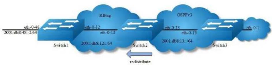
flowchart
graph LR
A["Switch1"] -->|eth-0-48 2001:db&48::2/64| B["RIPug"]
B -->|eth-0-12 2001:db&12::64| C["Switch2"]
C -->|eth-0-13 2001:db&13::/64| D["OSPFv3"]
D -->|eth-0-13 2001:db&13::/64| E["Switch3"]
E -->|eth-0-1| F["End"]
style A fill:#f9f,stroke:#333
style B fill:#bbf,stroke:#333
style C fill:#bfb,stroke:#333
style D fill:#ffb,stroke:#333
style E fill:#fbb,stroke:#333
style F fill:#fff,stroke:#333
note right of C "redistribute"
Figure 13-10 RIPng redistribute
This example shows how to redistribute other protocols into RIPng.
step 1 Check the current configuration
Current configuration of Switch1:
Switch# show running-config
!
ipv6 enable
!
interface eth-0-12
no switchport
ipv6 address auto link-local
ipv6 address 2001:db8:12::1/64
ipv6 router rip
!
interface eth-0-48
no switchport
ipv6 nd ra mtu suppress
ipv6 address auto link-local
ipv6 address 2001:db8:48::2/64
ipv6 router rip
!
router ipv6 rip
!
Current configuration of Switch2:
Switch# show running-config
!
ipv6 enable
!
interface eth-0-12
no switchport
ipv6 address auto link-local
ipv6 address 2001:db8:12::2/64
ipv6 router rip
!
interface eth-0-13
no switchport
ipv6 address auto link-local
ipv6 address 2001:db8:13::1/64
ipv6 router ospf area 0
!
interface eth-0-48
no switchport
ipv6 nd ra mtu suppress
ipv6 address auto link-local
ipv6 address 2001:ab8:48::2/64
ipv6 router rip
!
router ipv6 rip
!
router ipv6 ospf
router-id 1.1.1.1
Current configuration of Switch3:
Switch# show running-config
!
ipv6 enable
!
interface eth-0-1
no switchport
ipv6 address auto link-local
ipv6 address 2001:db8:1::1/64
ipv6 router ospf area 0
!
interface eth-0-13
no switchport
ipv6 address 2001:db8:13::2/64
ipv6 router ospf area 0
!
router ipv6 ospf
router-id 2.2.2.2
!
Check the RIPng states on Switch1:
Switch# show ipv6 route rip
R 2001:ab8:48::/64 [120/5]
via fe80::1271:d1ff:fec8:3300, eth-0-12, 01:43:37
Check the RIPng states on Switch2:
Switch# show ipv6 route
O 2001:db8:1::/64 [110/2]
via fe80::5c37:1dff:febe:2d00, eth-0-13, 00:31:17
R 2001:db8:48::/64 [100/5]
via fe80::7e14:63ff:fe76:8900, eth-0-12, 00:49:57
The following configurations are operated on Switch2:
step 2 Enter the configure mode
Switch# configure terminal
step 3 Enable redistribute, and et the default metric and redistribute metric
Switch(config)# router ipv6 rip
Switch(config-router)# default-metric 2
Switch(config-router)# redistribute ospfv3 metric 5
Switch(config-router)# exit
step 4 Exit the configure mode
Switch(config)# end
step 5 Validation
Display the result on Switch1:
Switch# show ipv6 route rip
R 2001:ab8:48::/64 [120/5]
via fe80::1271:d1ff:fec8:3300, eth-0-12, 01:48:23
R 2001:db8:1::/64 [120/6]
via fe80::1271:d1ff:fec8:3300, eth-0-12, 00:00:19
Configuring Split-horizon Parameters
Normally, routers that are connected to multicast-type IPv6 networks and that use distance-vector routing protocols employ the split horizon mechanism to reduce the possibility of routing loops. Split horizon blocks information about routes from
being advertised by a router out of any interface from which that information originated. This behavior usually optimizes communications among multiple routers, particularly when links are broken. However, with non-multicast networks (such as Frame Relay), situations can arise for which this behavior is less than ideal. For these situations, you might want to disable split horizon for RIPng.
You can avoid including routes in updates sent to the same gateway from which they were learned. Using the split horizon command omits routes learned from one neighbor, in updates sent to that neighbor. Using the poisoned parameter with this command includes such routes in updates, but sets their metrics to infinity. Thus, advertising these routes means that they are not reachable.

Figure 13-11 RIPng Split-horizon
step 1 Check the current configuration
Current configuration of Switch1:
Switch# show running-config
!
ipv6 enable
!
interface eth-0-12
no switchport
ipv6 address auto link-local
ipv6 address 2001:db8:12::1/64
ipv6 router rip
!
interface eth-0-48
no switchport
ipv6 nd ra mtu suppress
ipv6 address auto link-local
ipv6 address 2001:db8:48::2/64
ipv6 router rip
!
router ipv6 rip
!
Current configuration of Switch2:
Switch# show running-config
!
ipv6 enable
!
interface eth-0-12
no switchport
ipv6 address auto link-local
ipv6 address 2001:db8:12::2/64
ipv6 router rip
!
interface eth-0-48
no switchport
ipv6 nd ra mtu suppress
ipv6 address auto link-local
ipv6 address 2001:ab8:48::2/64
ipv6 router rip
!
router ipv6 rip
!
Enable debug on switch2
Switch# debug ipv6 rip packet send detail
Switch# terminal monitor
The following configurations are operated on Switch2:
step 2 Enter the configure mode
Switch# configure terminal
step 3 Set the split-horizon on interface configure mode
Disable split-horizon:
Switch(config)#interface eth-0-12
Switch(config-if)# no ipv6 rip split-horizon
Switch(config-if)# exit
System debug information:
Oct 24 10:00:06 Switch RIPNG6-7: SEND[eth-0-12]: Send to [ff02::9]:521
Oct 24 10:00:06 Switch RIPNG6-7: SEND[eth-0-12]: RESPONSE version 1 packet size 64
Oct 24 10:00:06 Switch RIPNG6-7: 2001:ab8:49::/64 metric 4 tag 0
Oct 24 10:00:06 Switch RIPNG6-7: 2001:db8:12::/64 metric 1 tag 0
Oct 24 10:00:06 Switch RIPNG6-7: 2001:db8:48::/64 metric 5 tag 0
Enable split-horizon:
Switch(config)#interface eth-0-12
Switch(config-if)#ipv6 rip split-horizon
Switch(config-if)#exit
System debug information:
Oct 24 10:05:16 Switch RIPNG6-7: SEND[eth-0-12]: Send to [ff02::9]:521
Oct 24 10:05:16 Switch RIPNG6-7: SEND[eth-0-12]: RESPONSE version 1 packet size 44
Oct 24 10:05:16 Switch RIPNG6-7: 2001:ab8:49::/64 metric 4 tag 0
Oct 24 10:05:16 Switch RIPNG6-7: 2001:db8:12::/64 metric 1 tag 0
step 3 Exit the configure mode
Switch(config)# end
step 4 Validation
Switch# show ipv6 rip interface
eth-0-12 is up, line protocol is up
Routing Protocol: RIPng
Passive interface: Disabled
Split horizon: Disabled
IPv6 interface address:
2001:ab8:48::2/64
2001:db8:12::2/64
fe80::7eff:80ff:fef4:ff00/10
Configuring Timers
RIPng use several timers that determine such variables as the frequency of routing updates, the length of time before a route becomes invalid, and other parameters. You can adjust these timers to tune RIPng performance to better suit your internetwork needs. You can make the following timer adjustments:
The rate (time in seconds between updates) at which routing updates are sent.
The interval of time (in seconds) after which a route is declared invalid.
The amount of time (in seconds) that must pass before a route is removed from the routing table.
To configure the timers, use the following command:
step 1 Enter the configure mode
Switch# configure terminal
step 2 Set the timers
Set the routing table update timer to 10 seconds. Set the routing information timeout timer to 180 seconds. Set the routing garbage collection timer to 120 seconds.
Switch(config)# router ipv6 rip
Switch(config-router)# Limers basic 10 180 120
Switch(config-router)# exit
step 3 Exit the configure mode
Switch(config)# end
step 4 Validation
Use the commands as follows to validate the configuration:
Switch# show ipv6 protocols rip
Routing Protocol is "ripng"
Sending updates every 10 seconds with +/-5 seconds, next due in 5 seconds
Timeout after 180 seconds, garbage collect after 120 seconds
Outgoing update filter list for all interface is not set
Incoming update filter list for all interface is not set
Outgoing routes will have 3 added to metric if on list ripng_acl
Default redistribute metric is 2
Redistributing:
Interface
eth-0-12
eth-0-48
Routing for Networks:
Number of routes (including connected): 3
Distance: (default is 100)
Configuring RIPng Route Distribute Filters
A RIP distribute list allows you to permit or deny learning or advertising of specific routes. A distribute list consists of the following parameters:
An ACL or a prefix list that filter the routes.
In: filter applies to learned routes.
Out: filter applies to advertised routes
The interface that the filer applies (optional).

flowchart
graph LR
A["Switch1"] -->|eth-0-48\n2001:db8:48::2/64| B["Switch2"]
B -->|eth-0-12\n2001:db8:12::/64| A
B -->|eth-0-12\n2001:ab8:48::2/64| C["Switch1"]
C -->|eth-0-48\n2001:ab8:48::2/64| D["Switch2"]
D -->|eth-0-13\n2001:db8:13::2/64| E["Switch2"]
Figure 13-12 RIPng Route Distribute Filters
step 1 Check the current configuration
Current configuration of Switch1:
Switch# show running-config
!
ipv6 enable
!
interface eth-0-12
no switchport
ipv6 address auto link-local
ipv6 address 2001:db8:12::1/64
ipv6 router rip
!
interface eth-0-48
no switchport
ipv6 nd ra mtu suppress
ipv6 address auto link-local
ipv6 address 2001:db8:48::2/64
ipv6 router rip
!
router ipv6 rip
Current configuration of Switch2:
Switch# show running-config
!
ipv6 enable
!
interface eth-0-12
no switchport
ipv6 address auto link-local
ipv6 address 2001:db8:12::2/64
ipv6 router rip
!
interface eth-0-13
no switchport
ipv6 address auto link-local
ipv6 address 2001:db8:13::1/64
ipv6 router rip
!
interface eth-0-48
no switchport
ipv6 nd ra mtu suppress
ipv6 address auto link-local
ipv6 address 2001:ab8:48::2/64
ipv6 router rip
!
router ipv6 rip
Check the RIPng states on Switch1:
Switch# show ipv6 route rip
R 2001:ab8:48::/64 [120/5]
via fe80::1271:d1ff:fec8:3300, eth-0-12, 00:18:29
R 2001:db8:13::/64 [120/2]
via fe80::1271:d1ff:fec8:3300, eth-0-12, 00:03:37
The following configurations are operated on Switch2:
step 2 Enter the configure mode
Switch# configure terminal
step 3 Create IPv6 Prefix list
Switch(config)# ipv6 prefix-list ripngfilter seq 5 deny 2001:db8:48::/64 Switch(config)# ipv6 prefix-list ripngfilter seq 10 permit any
step 4 Apply the IPv6 Prefix list
Switch(config)# router ipv6 rip Switch(config-router)# distribute-list prefix ripngfilter out eth-0-12 Switch(config-router)# exit
step 5 Exit the configure mode
Switch(config)# end
step 6 Validation
Display the result on Switch1:
Switch# show ipv6 route rip R 2001:db8:13::/64 [120/2] via fe80::1271:d1ff:fec8:3300, eth-0-12, 00:03:37
13.3.3 Application cases
N/A
13.4 Configuring IPv6 Prefix-list
13.4.1 Overview
Function Introduction
Routing Policy is the technology for modifying route information to change traffic route. IPv6 Prefix list is a kind of route policies that used to control and modify routing information. A IPv6 prefix list is identified by list name and contains one or more ordered entries which are processed sequentially. Each entry provides a matched range for network prefix and has a unique sequence number in the list. In
the matching process, switch will check entries orderly. If an entry matches conditions, this process would finish.
Principle Description
N/A
13.4.2 Configuration
Basic Configuration
step 1 Enter the configure mode
Switch# configure terminal
step 2 Create IPv6 Prefix list
Switch(config)# ipv6 prefix-list test seq 1 deny 2001:db8::1/32 le 48
Switch(config)# ipv6 prefix-list test permit any
Switch(config)# ipv6 prefix-list test description this ipv6 prefix list is fot test
Switch(config)# ipv6 prefix-list test permit 2001:abc::1/32 le 48
step 3 Exit the configure mode
Switch(config)# end
step 4 Validation
Switch# show ipv6 prefix-list detail
Prefix-list list number: 1
Prefix-list entry number: 3
Prefix-list with the last deletion/insertion: test
ipv6 prefix-list test:
Description: this ipv6 prefix list is fot test
count: 3, range entries: 0, sequences: 1 - 10
seq 1 deny 2001:db8::1/32 le 48 (hit count: 0, refcount: 0)
seq 5 permit any (hit count: 0, refcount: 0)
seq 10 permit 2001:abc::1/32 le 48 (hit count: 0, refcount: 0)
Used by RIPng
step 1 Enter the configure mode
Switch# configure terminal
step 2 Create IPv6 Prefix list
Switch(config)# ipv6 prefix-list aa seq 11 deny 2001:db8::1/32 le 48
Switch(config)# ipv6 prefix-list aa permit any
Step 3 Apply the IPv6 Prefix list
Switch(config)# router ipv6 rip
Switch(config-router)# distribute-list prefix aa out
Switch(config-router)# exit
step 4 Exit the configure mode
Switch(config)# end
step 5 Validation
Switch# show ipv6 prefix-list
ipv6 prefix-list aa: 2 entries
seq 11 deny 1:db8::1/32 le 48
seq 15 permit any
Switch# show running-config
Building configuration...
ipv6 prefix-list aa seq 11 deny 1:db8::1/32 le 48
ipv6 prefix-list aa seq 15 permit any
router ipv6 rip
distribute-list prefix aa out
Used by Route-map
step 1 Enter the configure mode
Switch# configure terminal
step 2 Create IPv6 Prefix list
Switch(config)# ipv6 prefix-list ripng_pre_1 seq 11 permit
fe80::a8f0:d8ff:fe7d:c501/128
Switch(config)# ipv6 prefix-list ripng_pre_1 permit any
step 3 Apply the IPv6 Prefix list to the route map
Switch(config)# route-map ripng_rmap permit
Switch(config-route-map)# match ipv6 address prefix-list ripng_pre_1
Switch(config-route-map)# set local-preference 200
Switch(config-route-map)# exit
step 4 Apply the route map to the RIPng instance
Switch(config)# router ipv6 rip
Switch(config-router)# redistribute static route-map ripng_rmap
Switch(config-router)# exit
step 5 Exit the configure mode
Switch(config)# end
step 6 Validation
Switch # show route-map
route-map ripng_rmap, permit, sequence 10
Match clauses:
ipv6 next-hop prefix-list ripng_pre_1
Set clauses:
ipv6 next-hop local fe80::1
Switch # show running-config
Building configuration...
ipv6 prefix-list ripng_pre_1 seq 11 permit fe80::a8f0:d8ff:fe7d:c501/128
ipv6 prefix-list ripng_pre_1 seq 15 permit any
!
!
route-map ripng_rmap permit 10
match ipv6 next-hop prefix-list ripng_pre_1
set ipv6 next-hop local fe80::1
!
router ipv6 rip
redistribute static route-map ripng_rmap
!
ipv6 route 2001:dbc::/64 fe80::a8f0:d8ff:fe7d:c501 eth-0-9
!
Switch# show ipv6 rip database
$ 2001:dbc::/64 fe80::1 eth-0-9 1 0
13.4.3 Application cases
N/A
14
IPv6 Multicast Configuration Guide
14.1 Configuring IPv6 Multicast-Routing
14.1.1 Overview
Function Introduction
Multicast protocols allow a group or channel to be accessed over different networks by multiple stations (clients) for the receipt and transmit of multicast data.
Distribution of stock quotes, video transmissions such as news services and remote classrooms, and video conferencing are all examples of applications that use multicast routing.
Multicast Listener Discovery (MLD) is used among hosts on a LAN and the routers (and multilayer switches) on that LAN to track the multicast groups of which hosts are members.
Protocol-Independent Multicast (PIM) protocol is used among routers and multilayer switches to track which multicast packets to forward to each other and to their directly connected LANs. PIM has two modes: Sparse-mode and Dense-mode. Currently, we only support Sparse-mode
Principle Description
N/A
14.1.2 Configuration
Configuring IPv6 multicast route limit
step 1 Enter the configure mode
Switch# configure terminal
step 2 Set the limit of the IPv6 multicast route
Switch(config)# ipv6 multicast route-limit 1000
step 3 Exit the configure mode
Switch(config)# end
step 4 Validation
Switch# show ipv6 mroute route-limit IPv6 Max Multicast Route Limit Number: 1000 IPv6 Multicast Route Limit Warning Threshold: 1000 IPv6 Multicast Hardware Route Limit: 255 IPv6 Current Multicast Route Entry Number: 0
14.1.3 Application cases
N/A
14.2 Configuring MLD
14.2.1 Overview
Function Introduction
To participate in IPv6 multicasting, multicast hosts, routers, and multilayer switches must have the MLD operating. This protocol defines the query and host roles:
A query is a network device that sends query messages to discover which network devices are members of a given multicast group.
A host is a receiver that sends report messages (in response to query messages) to inform a querier of a host membership.
A set of queries and hosts that receive IPv6 multicast data streams from the same source is called an IPv6 multicast group. Queries and hosts use MLD messages to join and leave IPv6 multicast groups. Any host, regardless of whether it is a member of a group, can send to a group. However, only the members of a group receive the message. Membership in a multicast group is dynamic; hosts can join and leave at any time. There is no restriction on the location or number of members in a multicast group.
A host can be a member of more than one multicast group at a time. How active a multicast group is and what members it has can vary from group to group and from time to time. A multicast group can be active for a long time, or it can be very short-lived. Membership in a group can constantly change. A group that has members can have no activity.
MLD packets are sent using these IPv6 multicast group addresses:
MLD general queries are destined to the address ff02::1 (all systems on a subnet).
MLD group-specific queries are destined to the group IPv6 address for which the switch is querying.
MLD group membership reports are destined to the group IPv6 address for which the switch is reporting.
MLD Version 1 (MLDv1) leave messages are destined to the address ff02::2 (all-multicast-routers on a subnet). In some old host IPv6 stacks, leave messages might be destined to the group IPv6 address rather than to the all-routers address.
Principle Description
The MLD module is based on the following RFC
RFC 2710
RFC 3810
14.2.2 Configuration
There is no explicit command to enable MLD, which is always combined with PIMv6-SM. When PIMv6-SM is enabled on an interface, MLD will be enabled automatically on this interface, vice versa. But notice, before MLD can work, IPv6 Multicast- routing must be enabled globally firstly. We support build MLD group record by learning MLD packets or configuring static MLD group by administer.
step 1 Enter the configure mode
Switch# configure terminal
step 2 Enable ipv6 and ipv6 multicast-routing globally
Switch(config)# ipv6 enable
Switch(config)# ipv6 multicast-routing
step 3 Enter the interface configure mode, set the ipv6 address and enable pim sparse mode
Switch(config)# interface eth-0-1
Switch(config-if)# no switchport
Switch(config-if)# ipv6 address 2001:1::1/64
Switch(config-if)# ipv6 pim sparse-mode
step 4 Configuring MLD Interface Parameters
Switch(config-if)# ipv6 mld version 2
Switch(config-if)# ipv6 mld query-interval 120
Switch(config-if)# ipv6 mld query-max-response-time 12
Switch(config-if)# ipv6 mld robustness-variable 3
Switch(config-if)# ipv6 mld last-member-query-count 3
Switch(config-if)# ipv6 mld last-member-query-interval 2000
step 5 Limit Max MLD Group Number
Set the maximum of ipv6 mld on the interface:
Switch(config-if)# ipv6 mld limit 1000
Switch(config-if)# exit
Set the maximum of ipv6 mld globally:
Switch(config)# ipv6 mld limit 2000
step 6 Create static mld group
Switch(config)# interface eth-0-1
Switch(config-if)# ipv6 mld static-group ff0e::1234
Switch(config-if)# exit
step 7 Set IPv6 MLD proxy (optional)
Switch(config)# interface eth-0-1
Switch(config-if)# no switchport
Switch(config-if)# ipv6 pim sparse-mode
Switch(config-if)# ipv6 mld proxy-service
Switch(config-if)# exit
Switch(config)# interface eth-0-2
Switch(config-if)# no switchport
Switch(config-if)# ipv6 pim sparse-mode
Switch(config-if)# ipv6 mld mroute-proxy eth-0-1
Switch(config-if)# exit
step 8 Exit the configure mode
Switch(config)# end
step 9 Validation
Displaying MLD Interface:
Switch# show ipv6 mld interface
Interface eth-0-2 (Index 2)
MLD Inactive, Version 1 (default)
MLD mroute-proxy interface is eth-0-1
MLD global limit is 2000
MLD global limit states count is currently 0
MLD interface limit is 4096
MLD interface has 0 group-record states
MLD activity: 0 joins, 0 leaves
MLD query interval is 125 seconds
MLD querier timeout is 255 seconds
MLD max query response time is 10 seconds
Last member query response interval is 1000 milliseconds
Group Membership interval is 260 seconds
Last memeber query count is 2
Robustness Variable is 2
Interface eth-0-1 (Index 1)
MLD Inactive, Configured for Version 2 proxy-service
MLD host version 2
MLD global limit is 2000
MLD global limit states count is currently 0
MLD interface limit is 1000
MLD interface has 0 group-record states
MLD activity: 0 joins, 0 leaves
MLD query interval is 120 seconds
MLD querier timeout is 366 seconds
MLD max query response time is 12 seconds
Last member query response interval is 2000 milliseconds
Group Membership interval is 372 seconds
Last memeber query count is 3
Robustness Variable is 3
Displaying MLD group:
Switch# show ipv6 mld groups
MLD Connected Group Membership
Group Address Interface Expires
ff0e::1234 eth-0-1 stopped
14.2.3 Application cases
N/A
14.3 Configuring PIMv6-SM
14.3.1 Overview
Function Introduction
The Protocol Independent Multicasting-Sparse Mode for IPv6 (PIMv6-SM) is a multicast routing protocol designed to operate efficiently across Wide Area Networks (WANs) with sparsely distributed groups. It helps network nodes that are geographically dispersed to conserve bandwidth, and reduces traffic by simultaneously delivering a single stream of information to multiple locations.
PIMv6-SM uses the IPv6 multicast model of receiver-initiated membership, supporting both shared and shortest-path trees, and uses soft-state mechanisms to adapt to changing network conditions. It relies on a topology-gathering protocol to populate a multicast routing table with routes.
Principle Description
The PIMv6-SM module is based on the following IETF standard: RFC 4601
Terminology:
Rendezvous Point (RP): A Rendezvous Point (RP) router is configured as the root of the non-source-specific distribution tree for a multicast group. Join messages from receivers for a group are sent towards the RP. Data from senders is sent to the RP so that receivers can discover who the senders are, and receive traffic destined for the group.
Multicast Routing Information Base (MRIB): The MRIB is a multicast topology table derived from the unicast routing table. In PIMv6-SM, the MRIB is used to decide where to send Join/Prune messages. It also provides routing metrics for destination addresses. These metrics are used when sending and processing Assert messages.
Reverse Path Forwarding: Reverse Path Forwarding (RPF) is a concept of an optimized form of flooding, where the router accepts a packet from SourceA through Interface IF1 only if IF1 is the interface the router would use in order to reach SourceA. It determines whether the interface is correct by consulting its unicast routing tables. The packet that arrives through interface IF1 is forwarded because the routing table lists this interface as the shortest path to the network. The router's unicast routing table determines the shortest path for the multicast packets. Because a router accepts a packet from only one neighbor, it floods the packet only once, meaning that (assuming point-to-point links) each packet is transmitted over each link once in each direction.
Tree Information Base (TIB): The TIB is the collection of state at a PIM router storing the state of all multicast distribution trees at that router. It is created by receiving Join/Prune messages, Assert messages, and MLD information from local hosts.
Upstream: Towards the root of the tree. The root of the tree might be either the Source or the RP.
➢ Downstream: Away from the root of the tree. The root of tree might be either the Source or the RP.
Source-Based Trees: In the Source-Based Trees concept, the forwarding paths are based on the shortest unicast path to the source. If the unicast routing metric is hop counts, the branches of the multicast Source-Based Trees are minimum hop. If the metric is delay, the branches are minimum delay. For every multicast source, there is a corresponding multicast tree that directly connects the source to all receivers. All traffic to the members of an associated group passes along the tree made for their source. Source-Based
Trees have two entries with a list of outgoing interfaces- the source address and the multicast group.
Shared Trees: Shared trees or RP trees (RPT) rely on a central router called the Rendezvous Point (RP) that receives all traffic from the sources, and forwards that traffic to the receivers. All hosts might not be receivers. There is a single tree for each multicast group, regardless of the number of sources. Only the routers on the tree know about the group, and information is sent only to interested receivers. With an RP, receivers have a place to join, even if no source exists. The shared tree is unidirectional, and information flows only from the RP to the receivers. If a host other than the RP has to send data on the tree, the data must first be tunneled to the RP, and then multicast to the members. This means that even if a receiver is also a source, it can only use the tree to receive packets from the RP, and not to send packets to the RP (unless the source is located between the RP and the receivers).
Bootstrap Router (BSR): When a new multicast sender starts sending data packets, or a new receiver starts sending the Join message towards the RP for that multicast group, it needs to know the next-hop router towards the RP. The BSR provides group-to-RP mapping information to all the PIMv6 routers in a domain, allowing them to map to the correct RP address.
Sending out Hello Messages: PIMv6 routers periodically send Hello messages to discover neighboring PIMv6 routers. Hello messages are multicast using the address ff02::d (ALL-PIMv6-ROUTERS group). Routers do not send any acknowledgement that a Hello message was received. A hold time value determines the length of time for which the information is valid. In PIMv6-SM, a downstream receiver must join a group before traffic is forwarded on the interface.
Electing a Designated Router: In a multi-access network with multiple routers connected, one of them is selected to act as a designated router (DR) for a given period of time. The DR is responsible for sending Join/Prune messages to the RP for local members.
Determining the RP: PIMv6-SM uses a Bootstrap Router (BSR) to originate Bootstrap messages, and to disseminate RP information. The messages are multicast to the group on each link. If the BSR is not apparent, the routers flood the domain with advertisements. The router with the highest priority (if priorities are same, the higher IPv6 address applies) is selected to be the RP.
Routers receive and store Bootstrap messages originated by the BSR. When a DR gets a membership indication from MLD for (or a data packet from) a directly connected host, for a group for which it has no entry, the DR maps the group address to one of the candidate RPs that can service that group. The DR then sends a Join/Prune message towards that RP. In a small domain, the RP can also be configured statically.
Joining the Shared Tree: To join a multicast group, a host sends an MLD message to its upstream router, after which the router can accept multicast traffic for that group. The router sends a Join message to its upstream PIMv6 neighbor in the direction of the RP. When a router receives a Join message from a downstream router, it checks to see if a state exists for the group in its multicast routing table. If a state already exists, the Join message has reached the shared tree, and the interface from which the message was received is entered in the Outgoing Interface list. If no state exists, an entry is created, the interface is entered in the Outgoing Interface list, and the Join message is again sent towards the RP.
Registering with the RP: A DR can begin receiving traffic from a source without having a Source or a Group state for that source. In this case, the DR has no information on how to get multicast traffic to the RP through a tree. When the source DR receives the initial multicast packet, it encapsulates it in a Register message, and unicasts it to the RP for that group. The RP decapsulates each Register message, and forwards the extracted data packet to downstream members on the RPT. Once the path is established from the source to the RP, the DR begins sending traffic to the RP as standard IPv6 multicast packets, as well as encapsulated within Register messages. The RP temporarily receives packets twice. When the RP detects the normal multicast packets, it sends a Register-Stop message to the source DR, meaning it should stop sending register packets.
Sending Register-Stop Messages: When the RP begins receiving traffic from the source, both as Register messages and as unencapsulated IPv6 packets, it sends a Register-Stop message to the DR. This notifies the DR that the traffic is now being received as standard IPv6 multicast packets on the SPT. When the DR receives this message, it stops encapsulating traffic in Register messages.
Pruning the Interface: Routers attached to receivers send Prune messages to the RP to disassociate the source from the RP. When an RP receives a Prune message, it no longer forwards traffic from the source indicated in the Prune
message. If all members of a multicast group are pruned, the MLD state of the DR is deleted, and the interface is removed from the Source and Group lists of the group.
Forwarding Multicast Packets: PIMv6-SM routers forward multicast traffic onto all interfaces that lead to receivers that have explicitly joined a multicast group. Messages are sent to a group address in the local subnetwork, and have a Time to Live (TTL) of 1. The router performs an RPF check, and forwards the packet. Traffic that arrives on the correct interface is sent onto all outgoing interfaces that lead to downstream receivers if the downstream router has sent a join to this router, or is a member of this group.
14.3.2 Configuration
Configuring General PIMv6 Sparse-mode (With static RP)
PIMv6-SM is a soft-state protocol. The main requirement is to enable PIMv6-SM on desired interfaces, and configure the RP information correctly, through static or dynamic methods. All multicast group states are maintained dynamically as the result of MLD Report/Leave and PIMv6 Join/Prune messages. Currently, we support only one RP for all multicast groups (ff00::/8).
This section provides PIMv6-SM configuration examples for two relevant scenarios.
In this example, using the above topology, Switch1 is the Rendezvous Point (RP), and all routers are statically configured with RP information. While configuring the RP, make sure that:
Every router includes the ipv6 pim rp-address 2001:1::1 statement, even if it does not have any source or group member attached to it.
There is only one RP address for a group scope in the PIMv6 domain.
All interfaces running PIMv6-SM must have sparse-mode enabled.

Figure 14-1 PIMv6 Sparse-mode
The graphic above displays the network topology used in these examples:
The following configuration should be operated on all switches if the switch ID is not specified.
step 1 Enter the configure mode
Switch# configure terminal
step 2 Enable IPv6 & IPv6 multicast globally
Switch(config)# ipv6 enable
Switch(config)# ipv6 multicast-routing
step 3 Enter the interface configure mode and set the attributes of the interface
Interface configuration for Switch1:
Switch(config)# interface eth-0-1
Switch(config-if)# no shutdown
Switch(config-if)# no switchport
Switch(config-if)# ipv6 address 2001:1::1/64
Switch(config-if)# ipv6 pim sparse-mode
Switch(config-if)# exit
Switch(config)# interface eth-0-9
Switch(config-if)# no shutdown
Switch(config-if)# no switchport
Switch(config-if)# ipv6 address 2001:9::1/64
Switch(config-if)# ipv6 pim sparse-mode
Switch(config-if)# exit
Interface configuration for Switch2:
Switch(config)# interface eth-0-1
Switch(config-if)# no shutdown
Switch(config-if)# no switchport
Switch(config-if)# ipv6 address 2001:2::1/64
Switch(config-if)# ipv6 pim sparse-mode
Switch(config-if)# exit
Switch(config)# interface eth-0-9
Switch(config-if)# no shutdown
Switch(config-if)# no switchport
Switch(config-if)# ipv6 address 2001:9::2/64
Switch(config-if)# ipv6 pim sparse-mode
Switch(config-if)# exit
step 4 Create static unicast routes
Configuring Switch1:
Switch(config)# ipv6 route 2001:2::/64 2001:9::2
Configuring Switch2:
Switch(config)# ipv6 route 2001:1::/64 2001:9::1
step 5 Configure static RP address
Switch(config)# ipv6 pim rp-address 2001:1::1
step 6 Exit the configure mode
Switch(config)# end
step 7 Validation
Configure all the routers with the same ipv6 pim rp-address 2001:1::1 command as shown above. Use the following commands to verify the RP configuration, interface details, and the multicast routing table.
RP Details
At Switch1, the show ip pim sparse-mode rp mapping command shows that 11.1.1.1 is the RP for all multicast groups ff00::/8, and is statically configured. All other routers will have a similar output.
Switch# show ipv6 pim sparse-mode rp mapping
PIM Group-to-RP Mappings
Group(s): ff00::/8, Static
RP: 2001:1::1
Uptime: 00:00:04
Embedded RP Groups:
Interface Details
The show ipv6 pim sparse-mode interface command displays the interface details for Switch1.
Switch# show ipv6 pim sparse-mode interface
Interface VIFindex Ver/ Nbr DR
Mode Count Prior
eth-0-1 2 v2/S 0 1
Address : fe80::fc94:efff:fe96:2600
Global Address: 2001:1::1
DR : this system
eth-0-9 0 v2/S 0 1
Address : fe80::fc94:efff:fe96:2600
Global Address: 2001:9::1
DR : this system
IPv6 Multicast Routing Table
The show ipv6 pim sparse-mode mroute detail command displays the IPv6 multicast routing table.
Display the result on Switch1:
Switch# show ipv6 pim sparse-mode mroute detail
IPv6 Multicast Routing Table
(*,*,RP) Entries: 0
(*,G) Entries: 1
(S,G) Entries: 0
(S,G,rpt) Entries: 0
FCR Entries: 0
*, ff0e::1234:5678
Type: (*,G)
Uptime: 00:01:37
RP: 2001:1::1, RPF nbr: None, RPF idx: None
Upstream:
State: JOINED, SPT Switch: Enabled, JT: off
Macro state: Join Desired,
Downstream:
eth-0-1:
State: NO INFO, ET: off, PPT: off
Assert State: NO INFO, AT: off
Winner: :,, Metric: 4294967295, Pref: 4294967295, RPT bit: on
Macro state: Could Assert, Assert Track
Local Olist:
eth-0-1
Display the result on Switch2:
Switch# show ipv6 pim sparse-mode mroute detail
IPv6 Multicast Routing Table
(*,*,RP) Entries: 0
(*,G) Entries: 1
(S,G) Entries: 0
(S,G,rpt) Entries: 0
FCR Entries: 0
*, ff0e::1234:5678
Type: (*,G)
Uptime: 00:00:06
RP: 2001:1::1, RPF nbr: None, RPF idx: None
Upstream:
State: JOINED, SPT Switch: Enabled, JT: off
Macro state: Join Desired,
Downstream:
eth-0-1:
State: NO INFO, ET: off, PPT: off
Assert State: NO INFO, AT: off
Winner: :,, Metric: 4294967295, Pref: 4294967295, RPT bit: on
Macro state: Could Assert, Assert Track
Local Olist:
eth-0-1
Configuring General PIMv6 Sparse-mode (With dynamic RP)
A static configuration of RP works for a small, stable PIMv6 domain; however, it is not practical for a large and not-suitable internet work. In such a network, if the RP fails, the network administrator might have to change the static configurations on all PIMv6 routers. Another reason for choosing dynamic configuration is a higher routing traffic leading to a change in the RP.
We use the BSR mechanism to dynamically maintain the RP information. For configuring RP dynamically in the above scenario, Switch1 on eth-0-1 and Switch2 on eth-0-9 are configured as Candidate RP using the ipv6 pim rp candidate command. Switch2 on eth-0-9 is also configured as Candidate BSR. Since no other router has been configured as Candidate BSR, the Switch2 becomes the BSR router, and is responsible for sending group-to-RP mapping information to all other routers in this PIMv6 domain.
The following output displays the complete configuration at Switch1 and Switch2.
The following configuration should be operated on all switches if the switch ID is not specified.
step 1 Enter the configure mode
Switch# configure terminal
step 2 Enable IPv6 & IPv6 multicast globally
Switch(config)# ipv6 enable
Switch(config)# ipv6 multicast-routing
step 3 Enter the interface configure mode and set the attributes of the interface
Interface configuration for Switch1:
Switch(config)# interface eth-0-1
Switch(config-if)# no shutdown
Switch(config-if)# no switchport
Switch(config-if)# ipv6 address 2001:1::1/64
Switch(config-if)# ipv6 pim sparse-mode
Switch(config-if)# exit
Switch(config)# interface eth-0-9
Switch(config-if)# no shutdown
Switch(config-if)# no switchport
Switch(config-if)# ipv6 address 2001:9::1/64
Switch(config-if)# ipv6 pim sparse-mode
Switch(config-if)# exit
Interface configuration for Switch2:
Switch(config)# interface eth-0-1
Switch(config-if)# no shutdown
Switch(config-if)# no switchport
Switch(config-if)# ipv6 address 2001:2::1/64
Switch(config-if)# ipv6 pim sparse-mode
Switch(config-if)# exit
Switch(config)# interface eth-0-9
Switch(config-if)# no shutdown
Switch(config-if)# no switchport
Switch(config-if)# ipv6 address 2001:9::2/64
Switch(config-if)# ipv6 pim sparse-mode
Switch(config-if)# exit
step 4 Create static unicast routes
Configuring Switch1:
Switch(config)# ipv6 route 2001:2::/64 2001:9::2
Configuring Switch2:
Switch(config)# ipv6 route 2001:1::/64 2001:9::1
step 5 Configure the candidate rp
Configuring Switch1:
Switch(config)# ipv6 pim rp-candidate eth-0-1
Configuring Switch2:
Switch(config)# ipv6 pim rp-candidate eth-0-9
step 6 Configure the candidate bsr
Configuring Switch2:
Switch(config)# ipv6 pim bsr-candidate eth-0-9

NOTE
The highest priority router is chosen as the RP. If two or more
routers have the same priority, a hash function in the BSR mechanism is used to
choose the RP, to make sure that all routers in the PIMv6-domain have the same RP for the same group.
step 7 Exit the configure mode
Switch(config)# end
step 8 Validation
PIMv6 group-to-RP mappings
Use the show ip pim sparse-mode rp mapping command to display the group-to-RP mapping details. The output displays information about RP candidates. There are two RP candidates for the group range ff00::/8. RP Candidate 2001:1::1 has a default priority of 192, whereas, RP Candidate 2001:9::2 has been configured to have a priority of 2. Since RP candidate 2001:1::1 has a higher priority, it is selected as RP for the multicast group ff00::/8. Only permit filters would be cared in group list.
Display the result on Switch2:
Switch# show ipv6 pim sparse-mode rp mapping
PIM Group-to-RP Mappings
This system is the Bootstrap Router (v2)
Group(s): ff00::/8
RP: 2001:9::2
Info source: 2001:9::2, via bootstrap, priority 2
Uptime: 00:00:32, expires: 00:02:02
RP: 2001:1::1
Info source: 2001:1::1, via bootstrap, priority 192
Uptime: 00:00:31, expires: 00:02:03
Embedded RP Groups:
RP details
To display information about the RP router for a particular group, use the following command. This output displays that 2001:9::2 has been chosen as the RP for the multicast group ff02::1234.
Display the result on Switch2:
Switch# show ipv6 pim sparse-mode rp-hash ff02::1234
Info source: 2001:9::2, via bootstrap

NOTE
After RP information reaches all PIMv6 routers in the domain, various state machines maintain all routing states as the result of Join/Prune from group membership. To display information on interface details and the multicast routing table, refer to the Configuring RP Statically section above.
Configuring Bootstrap Router
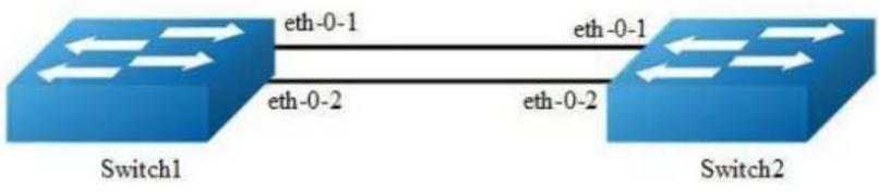
flowchart
graph LR
A["Switch1"] -->|eth-0-1| B["Switch2"]
B -->|eth-0-2| A
A -->|eth-0-2| B
Figure 14-2 BSR
Every PIMv6 multicast group needs to be associated with the IPv6 address of a Rendezvous Point (RP). This address is used as the root of a group-specific distribution tree whose branches extend to all nodes in the domain that want to receive traffic sent to the group. For all senders to reach all receivers, all routers in the domain use the same mappings of group addresses to RP addresses. In order to determine the RP for a multicast group, a PIMv6 router maintains a collection of group-to-RP mappings, called the RP-Set.
The Bootstrap Router (BSR) mechanism for the class of multicast routing protocols in the PIMv6 domain use the concept of a Rendezvous Point as a means for receivers to discover the sources that send to a particular multicast group. The BSR mechanism is one way that a multicast router can learn the set of group-to-RP mappings required in order to function.
Some of the PIMv6 routers within a PIMv6 domain are configured as Candidate-RPs (C-RPs). A subset of the C-RPs will eventually be used as the actual RPs for the domain. An RP configured with a lower value in the priority field has higher a priority.
Some of the PIMv6 routers in the domain are configured to be Candidate-BSRs (C-BSRs). One of these C-BSRs is elected to be the bootstrap router (BSR) for the domain, and all PIMv6 routers in the domain learn the result of this election through BSM (Bootstrap messages). The C-BSR with highest value in priority field is Elected-BSR.
The C-RPs then reports their candidacy to the elected BSR, which chooses a subset of the C-RPs and distributes corresponding group-to-RP mappings to all the routers in the domain through Bootstrap messages.
The following configuration should be operated on all switches if the switch ID is not specified.
step 1 Enter the configure mode
Switch# configure terminal
step 2 Enable IPv6 & IPv6 multicast globally
Switch(config)# ipv6 enable
Switch(config)# ipv6 multicast-routing
step 3 Configure the candidate bsr
Configuring Switch1:
Switch(config)# ipv6 pim bsr-candidate eth-0-1
Configuring Switch2:
Switch(config)# ipv6 pim bsr-candidate eth-0-1 10 25
step 4 Configure the candidate rp
Configuring Switch2:
Switch(config)# ipv6 pim rp-candidate eth-0-1 priority 0
step 5 Enter the interface configure mode and set the attributes of the interface
Interface configuration for Switch2:
Switch(config)# interface eth-0-1
Switch(config-if)# ipv6 pim dr-priority 10
Switch(config-if)# ipv6 pim unicast-bsm
Switch(config-if)# exit
step 5 Exit the configure mode
Switch(config)# end
step 6 Validation
Verify the C-BSR state on rtr1
Switch# show ipv6 pim sparse-mode bsr-router
PIM6v2 Bootstrap information
This system is the Bootstrap Router (BSR)
BSR address: 2001:9::1 (?)
Uptime: 00:01:27, BSR Priority: 64, Hash mask length: 126
Next bootstrap message in 00:00:16
Role: Candidate BSR
State: Elected BSR
Verify the C-BSR state on rtr2. The initial state of C-BSR is P-BSR before transitioning to C-BSR.
Switch# show ipv6 pim sparse-mode bsr-router
PIM6v2 Bootstrap information
BSR address: 2001:9::1 (?)
Uptime: 00:01:34, BSR Priority: 64, Hash mask length: 126
Expires: 00:01:51
Role: Candidate BSR
State: Candidate BSR
Candidate RP: 2001:9::2(eth-0-9)
Advertisement interval 60 seconds
Next C-RP advertisement in 00:00:35
Verify RP-set information on E-BSR
Switch# show ipv6 pim sparse-mode rp mapping
PIM Group-to-RP Mappings
This system is the Bootstrap Router (v2)
Group(s): ff00::/8
RP: 2001:9::2
Info source: 2001:9::2, via bootstrap, priority 0
Uptime: 00:45:37, expires: 00:02:29
Embedded RP Groups:
Verify RP-set information on C-BSR
Switch# show ipv6 pim sparse-mode rp mapping
PIM Group-to-RP Mappings
Group(s): ff00::/8
RP: 2001:9::2
Info source: 2001:9::1, via bootstrap, priority 0
Uptime: 00:03:14, expires: 00:01:51
Embedded RP Groups:
Configuring PIMv6-SSM feature
PIMv6-SSM can work with PIMv6-SM on the multicast router. By default, PIMv6-SSM is disabled.
step 1 Enter the configure mode
Switch# configure terminal
step 2 Enable PIMv6-ssm globally
Switch(config)# ipv6 pim ssm default Switch(config)# ipv6 pim ssm range ipv6acl
step 3 Exit the configure mode
Switch(config)# end
14.3.3 Application cases
N/A
14.4 Configuring PIMv6-DM
14.4.1 Overview
Function Introduction
The lpv6 Protocol Independent Multicasting-Dense Mode (PIMv6-DM) is a multicast routing protocol designed to operate efficiently across Wide Area Networks (WANs) with densely distributed groups. It helps network nodes that are geographically dispersed to conserve bandwidth, and reduces traffic by simultaneously delivering a single stream of information to multiple locations.
PIMv6-DM assumes that when a source starts sending, all down stream systems want to receive multicast datagrams. Initially, multicast datagrams are flooded to all areas of the network. PIMv6-DM uses RPF to prevent looping of multicast datagrams while flooding. If some areas of the network do not have group members, PIMv6-DM will prune off the forwarding branch by instantiating prune state.
Prune state has a finite lifetime. When that lifetime expires, data will again be forwarded down the previously pruned branch. Prune state is associated with an (S,G) pair. When a new member for a group G appears in a pruned area, a router can “graft” toward the source S for the group, thereby turning the pruned branch back into a forwarding branch.
Principle Description
The PIMv6-DM module is based on the following IETF standard: RFC 3973
14.4.2 Configuration
Configuring General PIM dense-mode
PIMv6-DM is a soft-state protocol. The main requirement is to enable PIMv6-DM on desired interfaces. All multicast group states are maintained dynamically as the result of MLD Report/Leave and PIMv6 messages.

Figure 14-3 PIMv6 dense-mode
This section provides PIMv6-DM configuration examples for two relevant scenarios.
The following graphic displays the network topology used in these examples: In this example, using the above topology, multicast data stream comes to eth-0-1 of Switch1, host is connected to eth-0-1 of Switch2. Here is a sample configuration:
The following configuration should be operated on all switches if the switch ID is not specified.
step 1 Enter the configure mode
Switch# configure terminal
step 2 Enable IPv6 & IPv6 multicast globally
Switch(config)# ipv6 enable
Switch(config)# ipv6 multicast-routing
step 3 Enter the interface configure mode and set the attributes of the interface
Interface configuration for Switch1:
Switch(config)# interface eth-0-1
Switch(config-if)# no shutdown
Switch(config-if)# no switchport
Switch(config-if)# ipv6 address 2001:1::1/64
Switch(config-if)# ipv6 pim dense-mode
Switch(config-if)# exit
Switch(config)# interface eth-0-9
Switch(config-if)# no shutdown
Switch(config-if)# no switchport
Switch(config-if)# ipv6 address 2001:2::1/64
Switch(config-if)# ipv6 pim dense-mode
Switch(config-if)# exit
Interface configuration for Switch2:
Switch(config)# interface eth-0-1
Switch(config-if)# no shutdown
Switch(config-if)# no switchport
Switch(config-if)# ipv6 address 2001:3::1/64
Switch(config-if)# ipv6 pim dense-mode
Switch(config-if)# exit
Switch(config)# interface eth-0-9
Switch(config-if)# no shutdown
Switch(config-if)# no switchport
Switch(config-if)# ipv6 address 2001:2::2/64
Switch(config-if)# ipv6 pim dense-mode
Switch(config-if)# exit
step 4 Create static unicast routes
Configuring Switch1:
Switch(config)# ipv6 route 2001:3::/64 2001:2::2
Configuring Switch2:
Switch(config)# ipv6 route 2001:1::/64 2001:2::1
step 5 Exit the configure mode
Switch(config)# end
step 6 Validation
Interface Details
The show ipv6 pim dense-mode interface command displays the interface details for Switch1.
Switch# show ipv6 pim dense-mode interface
Neighbor Address Interface VIFIndex Ver/ Nbr Mode Count
fe80::326f:c9ff:fef2:8200 eth-0-1 0 v2/D 0
fe80::326f:c9ff:fef2:8200 eth-0-9 2 v2/D 1
Neighbor Details
IP Multicast Routing Table
The show ip pim dense-mode mroute detail command displays the IP multicast routing table.
Display the result on Switch1:
Switch# show ipv6 pim dense-mode mroute
PIM-DM Multicast Routing Table
(2001:1::2, ff0e::1)
Source directly connected on eth-0-1
State-Refresh Originator State: Originator
Upstream IF: eth-0-1
Upstream State: Forwarding
Assert State: NoInfo
Downstream IF List:
eth-0-9, in 'olist':
Downstream State: NoInfo
Assert State: NoInfo
Display the result on Switch2:
Switch# show ipv6 pim dense-mode mroute
PIM-DM Multicast Routing Table
(2001:1::2, ff0e::1)
RPF Neighbor: none
Upstream IF: eth-0-9
Upstream State: AckPending
Assert State: Loser
Downstream IF List:
eth-0-1, in 'olist':
Downstream State: NoInfo
Assert State: NoInfo
14.4.3 Application cases
N/A
14.5 Configuring MLD Snooping
14.5.1 Overview
Function Introduction
Layer 2 switches can use MLD snooping to constrain the flooding of multicast traffic by dynamically configuring Layer 2 interfaces so that multicast traffic is forwarded only to those interfaces associated with IPv6 multicast devices. As the name implies, MLD snooping requires the LAN switch to snoop on the MLD transmissions between the host and the router and to keep track of multicast groups and member ports. When the switch receives an MLD report from a host for a particular multicast group, the switch adds the host port number to the forwarding table entry; when it receives an MLD Leave Group message from a host, it removes the host port from the table entry. It also deletes entries per entry if it does not receive MLD membership reports from the multicast clients. The multicast router sends out periodic general queries to all VLANs. All hosts interested in this multicast traffic send report and are added to the forwarding table entry. The switch forwards only one report per IPv6 multicast group to the multicast router. It creates one entry per VLAN in the Layer 2 forwarding table for each MAC group from which it receives an MLD report.
Layer 2 multicast groups learned through MLD snooping are dynamic. If you specify group membership for a multicast group address statically, your setting supersedes any automatic manipulation by MLD snooping. Multicast group membership lists can consist of both user-defined and MLD snooping-learned settings.

NOTE
Limitations And Configuration Guideline
VRRP, RIPng and OSPFv3 used multicast IPv6 address, so you need to avoid use such multicast IPv6 addresses, which have same multicast MAC address with multicast IPv6 address reserved by VRRP, RIPng and OSPFv3.
VRRP used multicast group address ff02::12, so when mld snooping and VRRP are working, you need to avoid using multicast group address that matched same mac address with group address ff02::12.
OSPFv3 used multicast group address ff02::5, so when mld snooping and OSFPv3 are working, you need to avoid using multicast group address that matched same mac address with group address ff02::5.
RIPng used multicast group address ff02::9, so when mld snooping and RIPng are working, you need to avoid using multicast group address that matched same mac address with group address ff02::9.
Principle Description
N/A
14.5.2 Configuration
Enable MLD Snooping
step 1 Enter the configure mode
Switch# configure terminal
step 2 Enable mld snooping globally
Switch(config)# ipv6 mld snooping
step 3 vlan 使能 mld snooping
Switch(config)#ipv6 mld snooping vlan 1
step 4 Exit the configure mode
Switch(config)# end
step 5 Validation
Switch # show ipv6 mld snooping vlan 1
Global Mld Snooping Configuration
Mld Snooping :Enabled
Mld Snooping Fast-Leave :Disabled
Mld Snooping Version 1
Mld Snooping Max-Member-Number 4096
Mld Snooping Unknown Multicast Behavior :Flood
Mld Snooping Report-Suppression :Enabled
Vlan 1
Mld Snooping :Enabled
Mld Snooping Fast-Leave :Disabled
Mld Snooping Report-Suppression :Enabled
Mld Snooping Version 1
Mld Snooping Max-Member-Number 4096
Mld Snooping Unknown Multicast Behavior :Flood
Mld Snooping Group Access-list :N/A
Mld Snooping Mrouter Port :
Mld Snooping Mrouter Port Aging Interval(sec) 255
Configuring Fast Leave
When MLD Snooping fast leave is enabled, the mld snooping group will be removed at once upon receiving a corresponding mld report. Otherwise the switch will send out specified mld specific query, if it doesn't get response in specified period, it will remove the group. By default, mld snooping fast-leave is disabled globally and per vlan.
step 1 Enter the configure mode
Switch# configure terminal
step 2 Enable fast leave globally
Switch(config)# ipv6 mld snooping fast-leave
step 3 Enable fast leave for a vlan
Switch(config)# ipv6 mld snooping vlan 1 fast-leave
step 4 Exit the configure mode
Switch(config)# end
step 5 Validation
Switch# show ipv6 mld snooping vlan 1
Global Mld Snooping Configuration
Mld Snooping :Enabled
Mld Snooping Fast-Leave :Enabled
Mld Snooping Version 1
Mld Snooping Max-Member-Number 4096
Mld Snooping Unknown Multicast Behavior :Flood
Mld Snooping Report-Suppression :Enabled
Vlan 1
Mld Snooping :Enabled
Mld Snooping Fast-Leave :Enabled
Mld Snooping Report-Suppression :Enabled
Mld Snooping Version 1
Mld Snooping Max-Member-Number 4096
Mld Snooping Unknown Multicast Behavior :Flood
Mld Snooping Group Access-list :N/A
Mld Snooping Mrouter Port :
Mld Snooping Mrouter Port Aging Interval(sec) 255
Configuring Querier Parameters (optional)
In order for MLD, and thus MLD snooping, to function, a multicast router must exist on the network and generate MLD queries. The tables created for snooping (holding the member ports for each multicast group) are associated with the querier. Without a querier the tables are not created and snooping will not work.
step 1 Enter the configure mode
Switch# configure terminal
step 2 Configuring Querier Parameters for MLD snooping
Set mld snooping query interval and max query response time:
Switch(config)# ipv6 mld snooping query-interval 100
Switch(config)# ipv6 mld snooping query-max-response-time 5
Set mld snooping last member query interval:
Switch(config)# ipv6 mld snooping last-member-query-interval 2000
Set mld snooping query parameters for vlan 1:
Switch(config)# ipv6 mld snooping vlan 1 querier address fe80::1
Switch(config)# ipv6 mld snooping vlan 1 querier
Switch(config)# ipv6 mld snooping vlan 1 query-interval 200
Switch(config)# ipv6 mld snooping vlan 1 query-max-response-time 5
Switch(config)# ipv6 mld snooping vlan 1 querier-timeout 100
Switch(config)# ipv6 mld snooping vlan 1 last-member-query-interval 2000
Switch(config)# ipv6 mld snooping vlan 1 discard-unknown
Discard unknown multicast packets globally:
Switch(config)# ipv6 mld snooping discard-unknown
step 3 Exit the configure mode
Switch(config)# end
step 4 Validation
Switch # show ipv6 mld snooping querier
Global Mld Snooping Querier Configuration
Version 1
Last-Member-Query-Interval (msec) :2000
Max-Query-Response-Time (sec) 5
Query-Interval (sec) 100
Global Source-Address :::
TCN Query Count 2
TCN Query Interval (sec) 10
Vlan 1: MLD snooping querier status
Elected querier is : fe80::1
Admin state :Enabled
Admin version 1
Operational state :Querier
Querier operational address :fe80::1
Querier configure address :fe80::1
Last-Member-Query-Interval (msec) :2000
Max-Query-Response-Time (sec) 5
Query-Interval (sec) 200
Querier-Timeout (sec) 100
Configuring Mrouter Port
An MLD Snooping mrouter port is a switch port which is assumed to connect a multicast router. The mrouter port is configured on the vlan or learnt dynamically. When MLD general query packet or PIMv6 hello packet is received on port of specified VLAN, this port becomes mrouter port of this vlan. All the mld queries received on this port will be flooded on the belonged vlan. All the mld reports and leaves received on this vlan will be forwarded to the mrouter port, directly or aggregated, depending on the report-suppression configuration. In addition, all the multicast traffic on this vlan will be forwarded to this mrouter port.
step 1 Enter the configure mode
Switch# configure terminal
step 2 Enable mld snooping report suppression globally
Switch(config)# ipv6 mld snooping report-suppression
step 3 Configure mrouter port
Switch(config)# ipv6 mld snooping vlan 1 mrouter interface eth-0-1
step 4 Configure mld snooping for parameters vlan
Enable mld snooping report suppression and Set mld snooping dynamic mrouter port aging interval:
Switch(config)# ipv6 mld snooping vlan 1 report-suppression
Switch(config)# ipv6 mld snooping vlan 1 mrouter-aging-interval 200
step 5 Exit the configure mode
Switch(config)# end
step 6 Validation
Switch# show ipv6 mld snooping vlan 1
Global Mld Snooping Configuration
Mld Snooping :Enabled
Mld Snooping Fast-Leave :Enabled
Mld Snooping Version 1
Mld Snooping Max-Member-Number 4096
Mld Snooping Unknown Multicast Behavior :Discard
Mld Snooping Report-Suppression :Enabled
Vlan 1
Mld Snooping :Enabled
Mld Snooping Fast-Leave :Enabled
Mld Snooping Report-Suppression :Enabled
Mld Snooping Version 1
Mld Snooping Max-Member-Number 4096
Mld Snooping Unknown Multicast Behavior :Discard
Mld Snooping Group Access-list :N/A
Mld Snooping Mrouter Port :eth-0-1(static)
Mld Snooping Mrouter Port Aging Interval(sec) 200
Configuring Querier Tcn
User can set the TCN interval and query count to adapt the multicast learning and updating after STP converging.
step 1 Enter the configure mode
Switch# configure terminal
step 2 Set the parameters for MLD Snooping querier TCN
Set mld snooping querier tcn query count and interval:
Switch(config)# ipv6 mld snooping querier tcn query-count 5
Switch(config)# ipv6 mld snooping querier tcn query-interval 20
step 3 Exit the configure mode
Switch(config)# end
step 4 Validation
Switch # show ipv6 mld snooping querier
Global Mld Snooping Querier Configuration
Version 1
Last-Member-Query-Interval (msec) :2000
Max-Query-Response-Time (sec) 5
Query-Interval (sec) 100
Global Source-Address :::
TCN Query Count 5
TCN Query Interval (sec) 20
Vlan 1: MLD snooping querier status
Elected querier is : fe80::1
Admin state :Enabled
Admin version 1
Operational state :Querier
Querier operational address :fe80::1
Querier configure address :fe80::1
Last-Member-Query-Interval (msec) :2000
Max-Query-Response-Time (sec) 5
Query-Interval (sec) 200
Querier-Timeout (sec) 100
Configuring Report Suppression
The switch uses MLD report suppression to forward only one MLD report per multicast router query to multicast devices. When MLD router suppression is enabled (the default), the switch sends the first MLD report from all hosts for a group to all the multicast routers. The switch does not send the remaining MLD reports for the group to the multicast routers. This feature prevents duplicate reports from being sent to the multicast devices.
step 1 Enter the configure mode
Switch# configure terminal
step 2 Enable mld snooping report suppression globally
Switch(config)# ipv6 mld snooping report-suppression
step 3 Enable mld snooping report suppression for a vlan
Switch(config)# ipv6 mld snooping vlan 1 report-suppression
step 4 Exit the configure mode
Switch(config)# end
step 5 Validation
Switch # show ipv6 mld snooping Global Mld Snooping Configuration
Mld Snooping :Enabled
Mld Snooping Fast-Leave :Disabled
Mld Snooping Version 2
Mld Snooping Max-Member-Number 4096
Mld Snooping Unknown Multicast Behavior :Flood
Mld Snooping Report-Suppression :Enabled
Vlan 1
Mld Snooping :Enabled
Mld Snooping Fast-Leave :Disabled
Mld Snooping Report-Suppression :Enabled
Mld Snooping Version 2
Mld Snooping Max-Member-Number 4096
Mld Snooping Unknown Multicast Behavior :Flood
Mld Snooping Group Access-list :N/A
Mld Snooping Mrouter Port :
Mld Snooping Mrouter Port Aging Interval(sec) 255
Configuring Static group
The switch can build MLD Snooping Group when receiving MLD report packet on Layer 2 port of specified VLAN. We also support configure static MLD Snooping Group by specifying MLD group, Layer 2 port and VLAN.
step 1 Enter the configure mode
Switch# configure terminal
step 2 Configure static group
Switch(config)# ipv6 mld snooping vlan 1 static-group ff0e::1234 interface eth-0-2
step 3 Exit the configure mode
Switch(config)# end
step 4 Validation
Switch# show ipv6 mld snooping groups
VLAN Interface Group Address Uptime Expire-time
1 eth-0-2 ff0e::1234 00:00:02 stopped
14.5.3 Application cases
N/A
14.6 Configuring MVR6
14.6.1 Overview
Function Introduction
Multicast VLAN Registration for IPv6 (MVR6) is designed for applications using wide-scale deployment of IPv6 multicast traffic across an Ethernet ring-based service provider network (for example, the broadcast of IPv6 multiple television channels over a service-provider network). MVR6 allows a subscriber on a port to subscribe and unsubscribe to an IPv6 multicast stream on the network-wide multicast VLAN. It allows the single multicast VLAN to be shared in the network while subscribers remain in separate VLANs. MVR6 provides the ability to continuously send IPv6 multicast streams in the multicast VLAN, but to isolate the streams from the subscriber VLANs for bandwidth and security reasons.
MVR6 assumes that subscriber ports subscribe and unsubscribe (join and leave) these multicast streams by sending out MLD join and leave messages. These
messages can originate from an MLD version-1-compatible host with an Ethernet connection. Although MVR6 operates on the underlying mechanism of MLD snooping, the two features operation affect with each other. One can be enabled or disabled with affecting the behavior of the other feature. If MLD snooping and MVR6 are both enabled, MVR6 reacts only to join and leave messages from IPv6 multicast groups configured under MVR6. The switch CPU identifies the MVR6 IPv6 multicast streams and their associated MAC addresses in the switch forwarding table, intercepts the MLD messages, and modifies the forwarding table to include or remove the subscriber as a receiver of the multicast stream, and the receivers must be in a different VLAN from the source. This forwarding behavior selectively allows traffic to cross between different VLANs.
Principle Description
N/A
14.6.2 Configuration
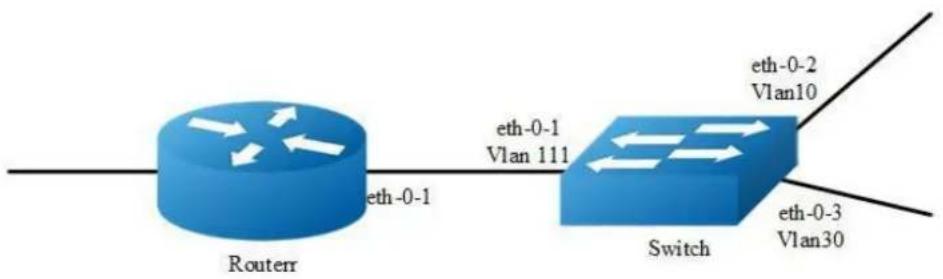
flowchart
graph LR
A["Router"] -->|eth-0-1| B["Switch"]
B -->|eth-0-2\nVlan10| C["Switch"]
B -->|eth-0-3\nVlan30| D["Switch"]
A -->|eth-0-1\nVlan 111| B
Figure 14-4 MVR6
step 1 Enter the configure mode
Configuring Switch:
Switch# configure terminal
Configuring Router:
Router# configure terminal
step 2 Enter the vlan configure mode and create VLANs
Configuring Switch:
Switch(config)# vlan database
Switch(config-vlan)# vlan 111,10,30
Switch(config-vlan)# quit
step 3 Enter the interface configure mode and set the attributes of the interface
Interface configuration for Router:
Router(config)# interface eth-0-1
Router(config-if)# no switchport
Router(config-if)# no shutdown
Router(config-if)# ipv6 address 2001:1::1/64
Router(config-if)# ipv6 pim sparse-mode
Router(config-if)# end
Interface configuration for Switch:
Switch(config)# interface vlan 111
Switch(config-if)# exit
Switch(config)# interface vlan 10
Switch(config-if)# exit
Switch(config)# interface vlan 30
Switch(config-if)# exit
Switch(config)# interface eth-0-1
Switch(config-if)# switchport access vlan111
Switch(config-if)# exit
Switch(config)# interface eth-0-2
Switch(config-if)# switchport access vlan10
Switch(config-if)# exit
Switch(config)# interface eth-0-3
Switch(config-if)# switchport access vlan30
Switch(config-if)# exit
step 4 Enable MVR6
Eanble MVR6 in the switch, it is required that only one copy of IPv6 multicast traffic from the Router is sent to the switch, but the hosts can both receiver this IPv6 multicast traffic.
Switch(config)# no ipv6 multicast-routing
Switch(config)# mvr6
Switch(config)# mvr6 vlan 111
Switch(config)# mvr6 group ff0e::1234 64
Switch(config)# mvr6 source-address fe80::1111
Switch(config)# interface eth-0-1
Switch(config-if)# mvr6 type source
Switch(config-if)# exit
Switch(config)# interface eth-0-2
Switch(config-if)# mvr6 type receiver vlan 10
Switch(config-if)# exit
Switch(config)# interface eth-0-3
Switch(config-if)# mvr6 type receiver vlan 30
Switch(config-if)# exit
step 5 Exit the configure mode
Switch(config)# end
step 6 Validation
Display the result on Router:
Router# show ipv6 mld groups
MLD Connected Group Membership
Group Address Interface Expires
ff0e::1234 eth-0-2 00:03:01
ff0e::1235 eth-0-2 00:03:01
ff0e::1236 eth-0-2 00:03:01
ff0e::1237 eth-0-2 00:03:01
ff0e::1238 eth-0-2 00:03:01
......
ff0e::1273 eth-0-2 00:03:01
Display the result on Switch:
Switch# show mvr6
MVR6 Running: TRUE
MVR6 Multicast VLAN: 111
MVR6 Source-address: fe80::111
MVR6 Max Multicast Groups: 1024
MVR6 Hw Rt Limit: 224
MVR6 Current Multicast Groups: 64
VLAN Interface Group Address Uptime Expire-time
10 eth-0-2 ff0e::1234 00:03:23 00:02:03
10 eth-0-2 ff0e::1235 00:03:23 00:02:03
10 eth-0-2 ff0e::1236 00:03:23 00:02:03
10 eth-0-2 ff0e::1237 00:03:23 00:02:03
10 cth-0-2 ff0e::1238 00:03:23 00:02:03
10 eth-0-2 ff0e::1239 00:03:23 00:02:03
......
10 cth-0-2 ff0e::1273 00:03:23 00:02:03
14.6.3 Application cases
N/A
15 VPN Configuration Guide
15.1 Configuring VPN
15.1.1 Overview
Function Introduction
VPN is defined as a collection of sites sharing a common routing table. A customer site is connected to the service provider network by one or more interfaces, where the service provider associates each interface with a VPN routing table. A VPN routing table is called a VPN routing and forwarding (VRF) table. Beginning in privileged EXEC mode, follow these steps to configure one or more VRFs.
Principle Description
N/A
15.1.2 Configuration
step 1 Enter the configure mode
Switch# configure terminal
step 2 Create a vrf instance
Switch(config)# ip vrf vpnl
Switch(config-vrf)# rd 100:1
Switch(config-vrf)# router-id 1.1.1.1
Switch(config-vrf)# route-target both 100:1
Switch(config-vrf)# import map route-map

NOTE
Enter either an AS system number
step 3 Enter the interface configure mode and set the attributes of the interface
Switch(config-vrf)# interface eth-0-1
Switch(config-if)# no shutdown
Switch(config-if)# no switch
Switch(config-if)# ip vrf forwarding vpnl
Switch(config-if)# ip add 1.1.1.1/24
Switch(config-if)# end
step 4 Exit the configure mode
Switch(config)# end
step 5 Validation
The result of show information about the configured VRFs:
Switch# show ip vrf
VRF vpn1, FIB ID 1
Router ID: 1.1.1.1 (config)
Interfaces:
eth-0-1
Switch# show ip vrf interfaces vpnl
Interface IP-Address VRF Protocol
eth-0-1 1.1.1.1 vpnl up
Switch# show ip vrf bgp brief
Name Default RD Interfaces
vpn1 100:1 eth-0-1
Switch# show ip vrf bgp detail
VRF vpn1; default RD 100:1
Interfaces:
eth-0-1
VRF Table ID = 1
Export VPN route-target communities
RT:100:1
Import VPN route-target communities
RT:100:1
import-map: route-map
No export route-map
15.1.3 Application cases
N/A
15.2 Configuring IPv4 GRE Tunnel
15.2.1 Overview
Function Introduction
Tunneling is an encapsulation technology, which uses one network protocol to encapsulate packet of another network protocol and transfer them over a virtual point to point connection. The virtual connection is called a tunnel. Tunneling refers to the whole process from data encapsulation to data transfer to data de-encapsulation.
Principle Description
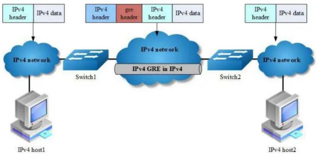
flowchart
graph TD
A["IPv4 host1"] --> B["IPv4 network"]
B --> C["Switch1"]
C --> D["IPv4 GRE in IPv4"]
D --> E["Switch2"]
E --> F["IPv4 network"]
G["IPv4 header"] --> B
H["IPv4 data"] --> B
I["IPv4 header"] --> D
J["gre header"] --> D
K["IPv4 header"] --> D
L["IPv4 data"] --> D
M["IPv4 header"] --> F
N["IPv4 data"] --> F
Figure 15-1 IPv4 gre over IPv4
When it is required to communicate with isolated IPv4 networks, you should create a tunnel mechanism between them. The tunnel with transmit protocol of gre connected with two isolated IPv4 island is called IPv4 gre tunnel, which is that IPv4 packets are encapsulated by gre protocol over outer IPv4 packets. Gre tunnel would add gre head in encapsulated packets, including key, sequence, checksum and so on. In order to make an implement of gre tunnel, both tunnel endpoints must support the IPv4 protocol stacks.
IPv4 gre tunnel processes packets in the following ways:
A host in the IPv4 network sends an IPv4 packet to Switch1 at the tunnel source.
After determining according to the routing table that the packet needs to be forwarded through the tunnel, Switch1 encapsulates the IPv4 packet with an IPv4 header and forwards it through the physical interface of the tunnel.
Upon receiving the packet, Switch2 de-encapsulates the packet.
Switch2 forwards the packet according to the destination address in the de-encapsulated IPv4 packet. If the destination address is the device itself, Switch2 forwards the IPv4 packet to the upper-layer protocol for processing. In the process of de-encapsulation, it would check gre key, only the matched key of packet can be processed, otherwise discarded.
The ip address of tunnel source and tunnel destination is manually assigned, and it provides point-to-point connection. By using overlay tunnels, you can communicate with isolated IPv4 networks without upgrading the IPv4 infrastructure between them. Overlay tunnels can be configured between border routers or between border routers and a host.
The primary use is for stable connections that require regular secure communication between two edge routers or between an end system and an edge router, or for connection to remote IPv4 networks, gre key is alternative configuration.
15.2.2 Configuration
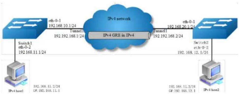
flowchart
graph LR
A["IPv4 host1"] -->|192.168.11.2/24| B["Tunnel1"]
B -->|192.192.168.1/24| C["IPv4 GRE in IPv4"]
C -->|192.192.168.2/24| D["Tunnel1"]
D -->|192.168.20.1/24| E["Switch2"]
E -->|192.168.12.1/24| F["IPv4 host2"]
G["Switch1"] -->|eth-0-1 192.168.10.1/24| H["Tunnel1"]
H -->|192.192.168.1/24| I["IPv4 network"]
I -->|eth-0-1 192.168.20.1/24| J["Switch2"]
Figure 15-2 IPv4 gre Tunnel
As the topology shows, two IPv4 networks connect to the network via Switch1 and Switch2. An IPv4 gre tunnel is required between Switch1 and Switch2, in order to connect two networks.

NOTE
A reachable lpv4 route is necessary for forwarding tunnel packet. Ipv4 address must be configured on tunnel interface; otherwise the route via this tunnel interface is invalid.
The following configuration should be operated on all switches if the switch ID is not specified.
step 1 Enter the configure mode
Switch# configure terminal
step 2 Enter the interface configure mode and set the attributes of the interface
Interface configuration for Switch1:
Switch(config)# interface eth-0-1
Switch(config-if)# no switchport
Switch(config-if)# no shutdown
Switch(config-if)# ip address 192.168.10.1/24
Switch(config-if)# tunnel enable
Switch(config-if)# exit
Switch(config)# interface eth-0-2
Switch(config-if)# no switchport
Switch(config-if)# no shutdown
Switch(config-if)# ip address 192.168.11.1/24
Switch(config-if)# exit
Interface configuration for Switch2:
Switch(config)# interface eth-0-1
Switch(config-if)# no switchport
Switch(config-if)# no shutdown
Switch(config-if)# ip address 192.168.20.1/24
Switch(config-if)# tunnel enable
Switch(config-if)# exit
Switch(config)# interface eth-0-2
Switch(config-if)# no switchport
Switch(config-if)# no shutdown
Switch(config-if)# ip address 192.168.12.1/24
Switch(config-if)# exit
step 3 Configure the tunnel interface
Tunnel interface configuration for Switch1:
Switch(config)# interface tunnell
Switch(config-if)# tunnel mode gre
Switch(config-if)# tunnel source eth-0-1
Switch(config-if)# tunnel destination 192.168.20.1
Switch(config-if)# tunnel gre key 100
Switch(config-if)# ip address 192.192.168.1/24
Switch(config-if)# keepalive 5 3
Switch(config-if)# exit
Tunnel interface configuration for Switch2:
Switch(config)# interface tunnell
Switch(config-if)# tunnel mode gre
Switch(config-if)# tunnel source eth-0-1
Switch(config-if)# tunnel destination 192.168.10.1
Switch(config-if)# tunnel gre key 100
Switch(config-if)# ip address 192.192.168.2/24
Switch(config-if)# keepalive 5 3
Switch(config-if)# exit
step 4 Configure the static route and arp
Configuring Switch1:
Switch(config)# ip route 192.168.20.0/24 192.168.10.2
Switch(config)# ip route 192.168.12.0/24 tunnel1
Configuring Switch2:
Switch(config)# ip route 192.168.10.0/24 192.168.20.2
Switch(config)# ip route 192.168.11.0/24 tunnel1
step 5 Exit the configure mode
Switch(config)# end
step 6 Validation
Display the result on Switch1:
Switch# show interface tunnel1
Interface tunnel1
Interface current state: UP
Hardware is Tunnel
Index 8193, Metric 1, Encapsulation TUNNEL
VRF binding: not bound
Internet primary address:
192.192.168.1/24 pointopoint 192.192.168.255
Tunnel protocol/transport GRE/IP, Status Valid
Tunnel source 192.168.10.1(eth-0-1), destination 192.168.20.1
Tunnel DSCP inherit, Tunnel TTL 255
Tunnel GRE key enable: 100
Tunnel GRE keepalive enable, Send period: 5, Retry times: 3
0 packets input, 0 bytes
0 packets output, 0 bytes
Display the result on Switch2:
Switch# show interface tunnel1
Interface tunnel1
Interface current state: UP
Hardware is Tunnel
Index 8193, Metric 1, Encapsulation TUNNEL
VRF binding: not bound
Internet primary address:
192.192.168.2/24 pointopoint 192.192.168.255
Tunnel protocol/transport GRE/IP, Status Valid
Tunnel source 192.168.20.1(eth-0-1), destination 192.168.10.1
Tunnel DSCP inherit, Tunnel TTL 255
Tunnel GRE key enable: 100
Tunnel GRE keepalive enable, Send period: 5, Retry times: 3
0 packets input, 0 bytes
0 packets output, 0 bytes
15.2.3 Application cases
N/A
16 Reliability Configuration Guide
16.1 Configuring BHM
16.1.1 Overview
Function Introduction
BHM is a module which is used to monitor other Processes. When a monitored Process is uncontrolled, the BHM module will take measures, such as printing warning on screen, shutting all ports, or restarting the system, to help or remind users to recover the system.
The monitored Processes include RIP, RIPNG, OSPF, OSPF6, BGP, LDP, RSVP, PIM, PIM6, 802.1X, LACP MSTP, DHCP-RELAY, DHCP-RELAY6, RMON, OAM, ONM, SSH, SNMP, PTP, SSM. In addition, some system procedures are also monitored, including NSM, IMI, CHSM, HSRVD. There are three activations of BHM, including “reload system”, including “reload system”, “warning”, “shutdown port”.
Principle Description
N/A
16.1.2 Configuration
step 1 Enter the configure mode
Switch# configure terminal
step 2 Enable system monitor and heart-beat-monitor globally
Switch(config)# sysmon enable Switch(config)# heart-beat-monitor enable
step 3 Reload system if a monitored PM is uncontrolled
Switch(config)# heart-beat-monitor reactivate reload system

NOTE
There are three activations of BHM, including “reload ng”, “shutdown port”.
step 4 Exit the configure mode
Switch(config)# end
step 5 Validation
Switch# show heart-beat-monitor
heart-beat-monitor enable.
heart-beat-monitor reactivation: restart system.
16.1.3 Application cases
N/A
16.2 Configuring EFM OAM
16.2.1 Overview
Function Introduction
This chapter contains a complete sample EFM OAM configuration. To see details on the commands used in this example, or to see the outputs of the validation commands, refer to the OAM Command Reference. To avoid repetition, some Common commands, like configure terminal, have not been listed under the commands used sections.
The main functions of Ethernet to the First Mile - Operation Administration and Maintenance (EFM-OAM) are link performance monitoring, fault detection, fault signaling and loopback signaling. OAM information is conveyed in Slow Protocol frames called OAM Protocol Data Units (OAMPDUs). OAMPDUs contain the appropriate control and status information used to monitor, test and troubleshoot OAM-enabled links.
Principle Description
Reference: IEEE 802.3ah (2004)
16.2.2 Configuration
Configuring Enable EFM

flowchart
graph LR
A["Switch1"] -->|eth-0-9| B["Switch2"]
B -->|eth-0-9| A
Figure 16-1 EFM
The following configurations are same on Switch1 and Switch2.
step 1 Enter the configure mode
Switch# configure terminal
step 2 Enter the interface configure mode and enable ethernet oam
Switch(config)# interface eth-0-9
Switch(config-if)# ethernet oam enable
Switch(config-if)# ethernet oam mode active
Switch(config-if)# ethernet oam link-monitor frame threshold high 10 window 50
Switch(config-if)# exit

NOTE
ethernet oam mode can be “active” or “passive”. For example:
Switch(config-if)# ethernet oam mode passive
At least one switch among Switch1 and Switch2 should use mode active. Both switch use active can also work normally.
step 4 Exit the configure mode
Switch(config)# end
step 5 Validation
The EFM Discovery Machine State should be “send any” in both machines. This is the expected normal operating state for OAM on fully-operational links.
The various states of OAM discovery state machine are defined below.
ACTIVE_SEND_LOCAL: A DTE configured in Active mode sends Information OAMPDUs that only contain the Local Information TLV. This state is called ACTIVE_SEND_LOCAL. While in this state, the local DTE waits for Information OAMPDUs received from the remote DTE.
PASSIVE_WAIT: DTE configured in Passive mode waits until receiving Information OAMPDUs with Local Information TLVs before sending any Information OAMPDUs with Local Information TLVs. This state is called PASSIVE_WAIT. By waiting until first receiving an Information OAMPDU with the Local Information TLV, a Passive DTE cannot complete the OAM Discovery process when connected to another Passive DTE.
SEND_LOCAL_REMOTE: Once the local DTE has received an Information OAMPDU with the Local Information TLV from the remote DTE, the local DTE begins sending Information OAMPDUs that contain both the Local and Remote Information TLVs. This state is called SEND_LOCAL_REMOTE.
SEND_LOCAL_REMOTE_OK: If the local OAM client deems the settings on both the local and remote DTEs are acceptable, it enters the SEND_LOCAL_REMOTE_OK state.
SEND_ANY: Once an OAMPDU has been received indicating the remote device is satisfied with the respective settings, the local device enters the SEND_ANY state. This is the expected normal operating state for OAM on fully operational links.
FAULT: If OAM is reset, disabled, or the link timer expires, the Discovery process returns to the FAULT state.
Display results on Switch1:
Switch# show ethernet oam discovery interface eth-0-9
eth-0-9
Local client:
Administrative configurations:
Mode: active
Unidirection: not supported
Link monitor: supported(on)
Remote Loopback: not supported
MIB retrieval: not supported
MTU Size : 1518
Operational status:
Port status: send any
Loopback status: no loopback
PDU revision: 1
Remote client:
MAC address: e6c2.47f6.7809
PDU revision: 1
Vendor(oui): c6 c2 47
Administrative configurations:
Mode: active
Unidirection: not supported
Link monitor: supported
Remote Loopback: not supported
MIB retrieval: not supported
MTU Size : 1518
Display results on Switch2:
Switch# show ethernet oam discovery interface eth-0-9
eth-0-9
Local client:
Administrative configurations:
Mode: active
Unidirection: not supported
Link monitor: supported(on)
Remote Loopback: not supported
MIB retrieval: not supported
MTU Size : 1518
Operational status:
Port status: operational
Loopback status: no loopback
PDU revision: 1
Remote client:
MAC address: 409c.bala.5a09
PDU revision: 1
Vendor(oui): 40 9c ba
Administrative configurations:
Mode: active
Unidirection: not supported
Link monitor: supported
Remote Loopback: not supported
MIB retrieval: not supported
MTU Size : 1518
Configuring Remote Loopback

flowchart
graph LR
A["Switch1"] -->|eth-0-9| B["Switch2"]
B -->|eth-0-9| A
Figure 16-2 EFM
OAM remote loopback can be used for fault localization and link performance testing. In addition, an implementation may analyze loopback frames within the OAM sublayer to determine additional information about the health of the link (i.e. determine which frames are being dropped due to link errors).
The following configurations are same on Switch1 and Switch2 if there is no special description.
step 1 Enter the configure mode
Switch# configure terminal
step 2 Enter the interface configure mode and enable ethernet oam remote loopback
Switch(config)# interface eth-0-9
Switch(config-if)# ethernet oam enable
Switch(config-if)# ethernet oam remote loopback supported
Switch(config-if)# exit
step 3 Exit the configure mode
Switch(config)# end
step 4 Start remote loopback
Configure on Switch1:
Switch# ethernet oam remote-loopback start interface eth-0-9
step 5 Validation
Display results on Switch1:
Switch# show ethernet oam state-machine interface eth-0-9
State Machine Details:
Local OAM mode: Active
Local OAM enable: Enable
Local link status: OK
Local pdu status: ANY
Local Satisfied: True
Local Stable: True
Remote Satisfied valid: True
Remote Stable: True
Local Parser State: Discard
Local Multiplexer State: Forward
Remote Parser State: Loopback Remote Multiplexer State: Discard
Configuring Link Monitoring Event

flowchart
graph LR
A["Switch1"] -->|eth-0-9| B["Switch2"]
B -->|eth-0-9| A
Figure 16-3 EFM
We can configure high and low threshold for link-monitoring features. We can also configure an error disable action if one of the high thresholds is exceeded.
The following configurations and validations are operated on Switch1:
step 1 Enter the configure mode
Switch# configure terminal
step 2 Enter the interface configure mode and set the threshold for error packetes
Switch(config)#interface eth-0-9
Switch(config-if)# ethernet oam link-monitor frame threshold high 5000 low 200 window 500
Switch(config-if)# ethernet oam link-monitor frame-seconds threshold high 600 low 200 window 9000

NOTE
The “ethernet oam link-monitor frame threshold” command high and low thresholds of error packets in a period. The period is ments “window 500”, the unit is 100 millisecond, the default value this case the high threshold is 5000 packets and the low threshold is
The “ethernet oam link-monitor frame-seconds threshold” command specifies the high and low thresholds of the seconds which have error packets in a period. The period is defined by arguments “window 9000”, the unit is 100 millisecond, the default value is 100 second. In this case the high threshold is 600 seconds and the low threshold is 200 seconds.
step 3 Set the action when reach the threshold
When the error packets exceed the threshold configured in step 2, set the interface status to error-disable
Switch(config-if)# ethernet oam link-monitor high-threshold action error-disable-interface
Switch(config-if)# exit
step 4 Exit the configure mode
Switch(config)# end
step 5 Validation
Switch#show ethernet oam status interface eth-0-9
eth-0-9
General:
Mode: active
PDU max rate: 1 packets per second
PDU min rate: 1 packet per 1 second
Link timeout: 10 seconds
High threshold action: disable interface
Link fault action: no action
Dying gasp action: no action
Critical event action: no action
Link Monitoring:
Status: supported(on)
Frame Error:
Window: 500 x 100 milliseconds
Low threshold: 200 error frame(s)
High threshold: 5000 error frame(s)
Last Window Frame Errors: 0 Frame(s)
Total Frame Errors: 0 Frame(s)
Total Frame Errors Events: 0 Events(s)
Relative Timestamp of the Event: 0 x 100 milliseconds
Frame Seconds Error:
Window: 9000 x 100 milliseconds
Low threshold: 200 error second(s)
High threshold: 600 error second(s)
Last Window Frame Second Errors: 0 error second(s)
Total Frame Second Errors: 0 error second(s)
Total Frame Second Errors Events: 0 Events(s)
Relative Timestamp of the Event: 0 x 100 milliseconds
Configuring Remote Failure Detection

flowchart
graph LR
A["Switch1"] -->|eth-0-9| B["Switch2"]
B -->|eth-0-9| A
Figure 16-4 EFM
An error-disable action can be configured to occur on an interface so that if any of the critical link events (link fault, dying gasp, etc.) occurs in the remote machine, the interface is shut down.
The following configurations and validations are operated on Switch1:
step 1 Enter the configure mode
Switch# configure terminal
step 2 Enter the interface configure mode and set action when the remote link failure
Switch(config)#interface eth-0-9
Switch(config-if)# ethernet oam remote-failure critical-event dying-gasp link-fault
action error-disable-interface
Switch(config-if)# exit
step 3 Exit the configure mode
Switch(config)# end
16.2.3 Application cases
N/A
16.3 Configuring CFM
16.3.1 Overview
Function Introduction
CFM = Connectivity Fault Management
CFM provides the capability to detect, verify, isolate and notify connectivity failures on a Virtual Bridged LAN based on the protocol standard specified in IEEE 802.1ag. It provides for discovery and verification of paths through 802.1 bridges and LANs, and is part of the enhanced Operation, Administration and Management (OAM) features. CFM is designed to be transparent to the customer data transported by a network and to be capable of providing maximum fault coverage.
Principle Description
Reference: IEEE 802.1ag/D8.1
CFM uses standard Ethernet frames distinguished by EtherType. These CFM messages are supported:
Continuity Check messages (CC)
Multicast heartbeat messages exchanged periodically between MEPs that allow MEPs to discover other MEPs within a domain and allow MIPs to discover MEPs. It is used to detect loss of continuity (LOC) between any pair of MEPs.
Loopback messages
Unicast frames transmitted by an MEP at administrator request to verify connectivity to a particular maintenance point, indicating if a destination is reachable. A loopback message is similar to an Internet Control Message Protocol (ICMP) ping message.
Linktrace messages
Multicast frames transmitted by an MEP at administrator request to track the path (hop-by-hop) to a destination MEP/MIP. Traceroute messages are similar in concept to UDP traceroute messages.
Delay Measurement messages
A MEP sends DMM with ETH-DM request information to its peer MEP and receives DMR with ETH-DM reply information from its peer MEP to carry out two-way frame delay and delay variation measurements.
When a MEP receives 1DM frames, it will carry out one-way frame delay and delay variation measurements.
Ethernet Locked Signal messages
Ethernet Locked Signal function (ETH-LCK) is used to communicate the administrative locking of a server (sub) layer MEP and consequential interruption of data traffic forwarding towards the MEP expecting this traffic. It allows a MEP receiving frames with ETH-LCK information to differentiate between a defect condition and an administrative locking action at the server (sub) layer MEP.
Ethernet client signal fail messages
The Ethernet client signal fail function (ETH-CSF) is used by a MEP to propagate to a peer MEP the detection of a failure or defect event in an Ethernet client signal when the client itself does not support appropriate fault or defect detection or propagation mechanisms, such as ETH-CC or ETH-AIS. The ETH-CSF messages propagate in the direction from the Ethernet source-adaptation function detecting the failure or defect event to the Ethernet sink-adaptation function associated with the peer MEP. ETH-CSF is only applicable to point-to-point Ethernet transport applications.
Ethernet Frame loss measurement message
ETH-LM is used to collect counter values applicable for ingress and egress service frames where the counters maintain a count of transmitted and received data frames between a pair of MEPs.
ETH-LM is performed by sending LMM with ETH-LM information to a peer MEP and similarly receiving LMR with ETH-LM information from the peer MEP.
16.3.2 Configuration

CFM is conflict with 802.1x and mirror destination on the same port. The, CFM and these functions should not be configured on the same port.
Configure CC/LB/LT/AIS/DM
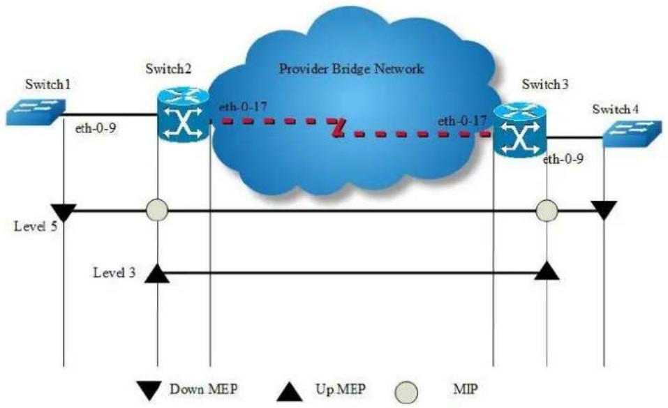
flowchart
graph LR
Switch1["Switch1"] -->|eth-0-9| Switch2["Switch2"]
Switch2 -->|eth-0-17| ProviderBridge["Provider Bridge Network"]
Switch2 -->|eth-0-17| Switch3["Switch3"]
Switch3 -->|eth-0-9| Switch4["Switch4"]
Switch1 -->|Level 5| Level3
Switch2 -->|Level 5| Level3
Switch3 -->|Level 5| Level3
Switch4 -->|Level 5| Level3
style ProviderBridge fill:#888,stroke:#333
style Switch1 fill:#ccc,stroke:#333
style Switch2 fill:#fff,stroke:#333
style Switch3 fill:#fff,stroke:#333
style Switch4 fill:#ccc,stroke:#333
Figure 16-5 CFM
The following configuration should be operated on all switches if the switch ID is not specified.
step 1 Enter the configure mode
Switch# configure terminal
step 2 Enter the vlan configure mode and create the vlan
Switch(config)# vlan database
Switch(config vlan)# vlan 30
Switch(config vlan)# exit
step 3 Enable CFM globally and set cfm mode to y1731
Switch(config)# ethernet cfm enable
Switch(config)# ethernet cfm mode y1731
step 4 Create the cfm domain and bind the service with a vlan
Create a domain which has the name "cust" and level 5.
Switch(config)# ethernet cfm domain cust level 5
Switch(config-ether-cfm)# service cst vlan 30
Switch(config-ether-cfm)# exit
Create a domain which has the name "provid" and level 3.
Configuring Switch2 and Switch3:
Switch(config)# ethernet cfm domain provid level 3
Switch(config-ether-cfm)# service cst vlan 30
Switch(config-ether-cfm)# exit

NOTE
The range of the cfm domain level should be 0-7. The larger number indicates the higher priority. When different cfm domains have the same vlan, the packets of the domain with higher priority can pass through the domains with lower priority.
step 5 Enter the interface configure mode and set the attributes of the interface
Interface configuration for Switch1:
Switch(config)# interface eth-0-9
Switch(config-if)# switchport mode trunk
Switch(config-if)# switchport trunk allowed vlan add 30
Switch(config-if)# ethernet cfm mep down mpid 66 domain cust vlan 30 interval 1
Switch(config-if)# ethernet cfm mep crosscheck mpid 99 domain cust vlan 30 mac d036.4567.8009
Switch(config-if)# no shutdown
Switch(config-if)# exit
Interface configuration for Switch2:
Switch(config)# interface eth-0-9
Switch(config-if)# switchport mode trunk
Switch(config-if)# switchport trunk allowed vlan add 30
Switch(config-if)# ethernet cfm mip level 5 vlan 30
Switch(config-if)# ethernet cfm mep up mpid 666 domain provid vlan 30 interval 1
Switch(config-if)# ethernet cfm mep crosscheck mpid 999 domain provid vlan 30 mac 6a08.05le.bd09
Switch(config-if)# ethernet cfm ais status enable all domain provid vlan 30 level 5 multicast
Switch(config-if)# ethernet cfm server-ais status enable level 5 interval 1
Switch(config-if)# no shutdown
Switch(config-if)# exit
Switch(config)# interface eth-0-17
Switch(config-if)# switchport mode trunk
Switch(config-if)# switchport trunk allowed vlan add 30
Switch(config-if)# no shutdown
Switch(config-if)# exit
Interface configuration for Switch3:
Switch(config)# interface eth-0-9
Switch(config-if)# switchport mode trunk
Switch(config-if)# switchport trunk allowed vlan add 30
Switch(config-if)# ethernet cfm mip level 5 vlan 30
Switch(config-if)# ethernet cfm mep up mpid 999 domain provid vlan 30 interval 1
Switch(config-if)# ethernet cfm mep crosscheck mpid 666 domain provid vlan 30 mac
Oeld.a7d7.fb09
Switch(config-if)# no shutdown
Switch(config-if)# exit
Switch(config)# interface eth-0-17
Switch(config-if)# switchport mode trunk
Switch(config-if)# switchport trunk allowed vlan add 30
Switch(config-if)# no shutdown
Switch(config-if)# exit
Interface configuration for Switch4:
Switch(config)# interface eth-0-9
Switch(config-if)# switchport mode trunk
Switch(config-if)# switchport trunk allowed vlan add 30
Switch(config-if)# ethernet cfm mep down mpid 99 domain cust vlan 30 interval 1
Switch(config-if)# ethernet cfm mep crosscheck mpid 66 domain cust vlan 30 mac fa02.cdff.6a09
Switch(config-if)# no shutdown
Switch(config-if)# exit
step 6 Enable continuity check
Configuring Switch1 and Switch4:
Switch1(config)# ethernet cfm cc enable domain cust vlan 30
Configuring Switch2 and Switch3:
Switch2(config)# ethernet cfm cc enable domain provid vlan 30
step 7 Alarm configuration (optional)
Suppress errors when ais packet is received and loc error.
Configuring Switch1:
Switch(config)# ethernet cfm ais suppress alarm enable domain cust vlan 30
step 8 Exit the configure mode
Switch(config)# end
step 9 Validation
MEP and MIP checks
The following command gives the connectivity details of the local machine Switch1 and Switch2 for the configured domain.
Switch1:
Switch# show ethernet cfm maintenance-points
######Local MEP:
MPID Direction DOMAIN LEVEL TYPE VLAN PORT CC-Status Mac-address RDI
Interval
---
66 Down MEP cust 5 MEP 30 eth-0-9 enabled fa02.cdff.6a09 True
3.33ms
######Local MIP:
Level VID TYPE PO RT MAC
###
####Remote MEP:
MPID LEVEL VLAN ACTIVE Remote Mac RDI FLAGS STATE
99 5 30 Yes d036.4567.8009 True Learnt UP
Switch2:
Switch# show ethernet cfm maintenance-points
######Local MEP:
MPID Direction DOMAIN LEVEL TYPE VLAN PORT CC-Status Mac-address RDI
666 Up MEP provid 3 MEP 30 eth-0-9 enabled 0e1d.a7d7.fb09 False
######Local MIP:
Level VID TYPE PORT MAC
5 30 MIP eth-0-9 0e1d.a7d7.fb09
######Remote MEP:
MPID LEVEL VLAN ACTIVE Remote Mac RDI FLAGS STATE
999 3 30 Yes 6a08.05le.bd09 True Learnt UP
Loopback checks
The following command is used to ping remote mep by remote mep unicast mac address on Switch1.
Switch# ethernet cfm loopback mac d036.4567.8009 unicast mepid 66 domain cust vlan
30
Sending 1 Ethernet CFM loopback messages, timeout is 5 seconds:
(! Pass . Fail)
!
Loopback completed.
Success rate is 100 percent(1/1)
The following command is used to ping remote mep by multicast mac address on Switch1.
Switch# ethernet cfm loopback multicast mepid 66 domain cust vlan 30
Sending 1 Ethernet CFM loopback messages, timeout is 5 seconds:
(! Pass . Fail)
Host MEP: 66
Number of RMEPs that replied to mcast frame = 1
LBR received from the following
9667.bb68.f308
success rate is 100 (1/1)
The following command is used to ping remote mep by remote mep id on Switch1.
Switch# ethernet cfm loopback unicast rmepid 99 mepid 66 domain cust vlan 30
Sending 1 Ethernet CFM loopback messages, timeout is 5 seconds:
(! Pass . Fail)
!
Loopback completed.
----
Success rate is 100 percent(1/1)
The following command is used to ping mip by mip mac address on Switch1.
Switch# ethernet cfm loopback mac 0eld.a7d7.fb09 unicast mepid 66 domain cust vlan 30
Sending 1 Ethernet CFM loopback messages, timeout is 5 seconds:
(! Pass . Fail)
!
Loopback completed.
----
Success rate is 100 percent(1/1)
RDI checks
Before clear local mep rdi, the rdi status on Switch1 is as follows:
Switch# show ethernet cfm maintenance-points local mep domain cust
MPID Direction DOMAIN LEVEL TYPE VLAN PORT CC-Status Mac-address RDI Interval
66 Down MEP cust 5 MEP 30 eth-0-9 enabled fa02.cdff.6a09 True 3.33ms
ERROR checks
Before clear local mep errors, the errors on Switch1 are as follows:
Switch# show ethernet cfm errors domain cust
Level Vlan MPID RemoteMac Reason ServiceId
5 30 66 d036.4567.8009 errorCCMdefect: rmep not found cst
5 30 66 d036.4567.8009 errorCCMdefect: rmep not found clear cst
Time
2011/05/27 3:19:18
2011/05/27 3:19:32
The following command is used to clear errors on Switch1.
Switch# clear ethernet cfm errors domain cust
After clear local mep errors, the errors on Switch1 are as follows:
Switch# clear ethernet cfm errors domain cust
Level Vlan MPID RemoteMac Reason ServiceId
AIS check
The following command is used to disable cc function in Switch1.
Switch(config)# no ethernet cfm cc enable domain cust vlan 30
The following command is used to disable cc function in Switch3.
Switch(config)# no ethernet cfm cc enable domain cust vlan 30
The following command is used to check ais defect condition in Switch2.
Switch# show ethernet cfm ais mep 666 domain cust vlan 30
AIS-Status: Enabled
AIS Period: 1
Level to transmit AIS: 7
AIS Condition: No
Configured defect condition detected(yes/no)
unexpected-period no
unexpected-MEG level no
unexpected-MEP no
Mismerge no
LOC yes
The following command is used to check ais reception status in Switch1.
Switch# show ethernet cfm ais mep 66 domain cust vlan 30
AIS-Status: Disabled
AIS Condition: Yes
LinkTrace checks
The following command is used to link trace remote mep by remote mep unicast mac address on Switch1.
Switch# ethernet cfm linktrace mac d036.4567.8009 mepid 66 domain cust vlan 30
Sending Ethernet CFM linktrace messages, TTL is 64.Per-Hop Timeout is 5 seconds:
Please wait a moment
Received Hops: 1
TTL : 63
Fowarded : True
Terminal MEP : False
Relay Action : Rly FDB
Ingress Action : IngOk
Ingress MAC address : 0e1d.a7d7.fb09
Ingress Port ID Type : ifName
Ingress Port ID : eth-0-9
Received Hops: 2
TTL : 62
Fowarded : True
Terminal MEP : False
Relay Action : Rly FDB
Egress Action : EgrOk
Egress MAC address : 6a08.051e.bd09
Egress Port ID Type : ifName
Egress Port ID : eth-0-9
Received Hops: 3
TTL : 61
Fowarded : False
Terminal MEP : True
Relay Action : Rly Hit
Ingress Action : IngOk
Ingress MAC address : d036.4567.8009
Ingress Port ID Type : ifName
Ingress Port ID : eth-0-9
The following command is used to link trace remote mep by remote mep id on Switch1.
Switch# ethernet cfm linktrace rmepid 99 mepid 66 domain cust vlan 30
Sending Ethernet CFM linktrace messages, TTL is 64.Per-Hop Timeout is 5 seconds:
Please wait a moment
Received Hops: 1
TTL : 63
Fowarded : True
Terminal MEP : False
Relay Action : Rly FDB
Ingress Action : IngOk
Ingress MAC address : 0e1d.a7d7.fb09
Ingress Port ID Type : ifName
Ingress Port ID : eth-0-9
Received Hops: 2
TTL : 62
Fowarded : True
Terminal MEP : False
Relay Action : Rly FDB
Egress Action : EgrOk
Egress MAC address : 6a08.051e.bd09
Egress Port ID Type : ifName
Egress Port ID : eth-0-9
Received Hops: 3
TTL : 61
Fowarded : False
Terminal MEP : True
Relay Action : Rly Hit
Ingress Action : IngOk
Ingress MAC address : d036.4567.8009
Ingress Port ID Type : ifName
Ingress Port ID : eth-0-9
The following command is used to link trace remote mip by remote mip unicast mac address on Switch1.
Switch# ethernet cfm linktrace 6a08.05le.bd09 mepid 66 domain cust vlan 30
Sending Ethernet CFM linktrace messages, TTL is 64.Per-Hop Timeout is 5 seconds:
Please wait a moment
Received Hops: 1
TTL : 63
Fowarded : True
Terminal MEP : False
Relay Action : Rly FDB
Ingress Action : IngOk
Ingress MAC address : 0eld.a7d7.fb09
Ingress Port ID Type : ifName
Ingress Port ID : eth-0-9
Received Hops: 2
TTL : 62
Fowarded : False
Terminal MEP : False
Relay Action : Rly Hit
Egress Action : EgrOk
Egress MAC address : 6a08.051e.bd09
Egress Port ID Type : ifName
Egress Port ID : eth-0-9
1DM and DMM checks
The following command is used to make two way delay and delay variation measurement on Switch1.
Switch# ethernet cfm dmm rmepid 99 mepid 66 count 5 domain cust vlan 30
Delay measurement statistics:
DMM Packets transmitted : 5
Valid DMR packets received : 5
Index Two-way delay Two-way delay variation
1 4288 usec 0 usec
2 4312 usec 24 usec
3 4296 usec 16 usec
4 4320 usec 24 usec
5 4264 usec 56 usec
Average delay : 4296 usec
Average delay variation : 24 usec
Best case delay : 4264 usec
Worst case delay : 4320 usec
Before make one way delay measurement, clock timer should be synchronized. The following command is used to start sending 1dm message in Switch1.
Switch1#ethernet cfm 1dm rmepid 99 mepid 66 count 5 domain cust vlan 30
The following is 1dm test result in Switch4.
Switch4# show ethernet cfm delaymeasurement cache
Remote MEP : 66
Remote MEP vlan : 30
Remote MEP level : 5
DMM Packets transmitted : 0
Valid DMR packets received : 0
Valid lDM packets received : 5
Index One-way delay One-way delay variation Received Time
1 16832 usec 0 usec 2011/07/19 17:27:46
2 16176 usec 656 usec 2011/07/19 17:27:47
3 15448 usec 728 usec 2011/07/19 17:27:48
4 14800 usec 648 usec 2011/07/19 17:27:49
5 15406 usec 606 usec 2011/07/19 17:27:50
Average delay : 15732 usec
Average delay variation : 527 usec
Best case delay : 14800 usec
Worst case delay : 16832 usec
Configure LCK
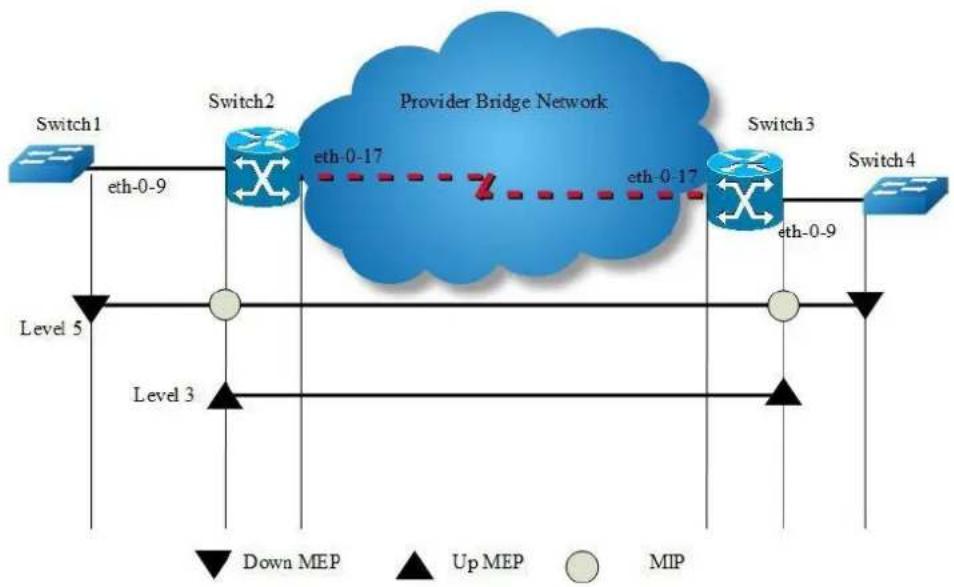
flowchart
graph LR
Switch1["Switch1"] -->|eth-0-9| Switch2["Switch2"]
Switch2 -->|eth-0-17| ProviderBridge["Provider Bridge Network"]
Switch2 -->|Z| Switch3["Switch3"]
Switch3 -->|eth-0-9| Switch4["Switch4"]
Switch3 -->|eth-0-17| Switch2
Switch2 -->|Level 5| Level3["Level 3"]
Switch3 -->|Level 3| Level5["Level 5"]
Switch4 -->|Down MEP| Switch1
Switch4 -->|Up MEP| Switch2
Switch4 -->|MIP| Switch3
Figure 16-6 CFM
step 1 Configuration prepare
Reference to the chapter "Configure CC/LB/LT/AIS/DM".
step 2 Configure LCK
Configuring Switch2:
Switch(config)# interface eth-0-9
Switch(config-if)# ethernet cfm lck enable mep 666 domain provid vlan 30 tx-level 5 interval 1
step 3 Validation
The following command is used to display lck status for Switch2:
Switch2# show ethernet cfm lck
En-LCK Enable, Y(Yes)/N(No)
Rx-LC, Receive LCK packets and enter LCK condition, Y(Yes)/N(No)
Rx-I, The period which is gotten from LCK packets
Tx-Domain, frames with ETH-LCK information are sent to this Domain
Tx-I, Transmit Interval
MPID Domain VLAN En Rx-LC Rx-I Tx-Domain Tx-I
666 provid 30 Y N N/A cust 1
The following command is used to display lck status for Switch1:
Switch1# show ethernet cfm lck
En-LCK Enable, Y(Yes)/N(No)
Rx-LC, Receive LCK packets and enter LCK condition, Y(Yes)/N(No)
Rx-I, The period which is gotten from LCK packets
Tx-Domain, frames with ETH-LCK information are sent to this Domain
Tx-I, Transmit Interval
MPID Domain VLAN En Rx-LC Rx-I Tx-Domain Tx-I
66 cust 30 N Y 1 N/A N/A
Configure CSF
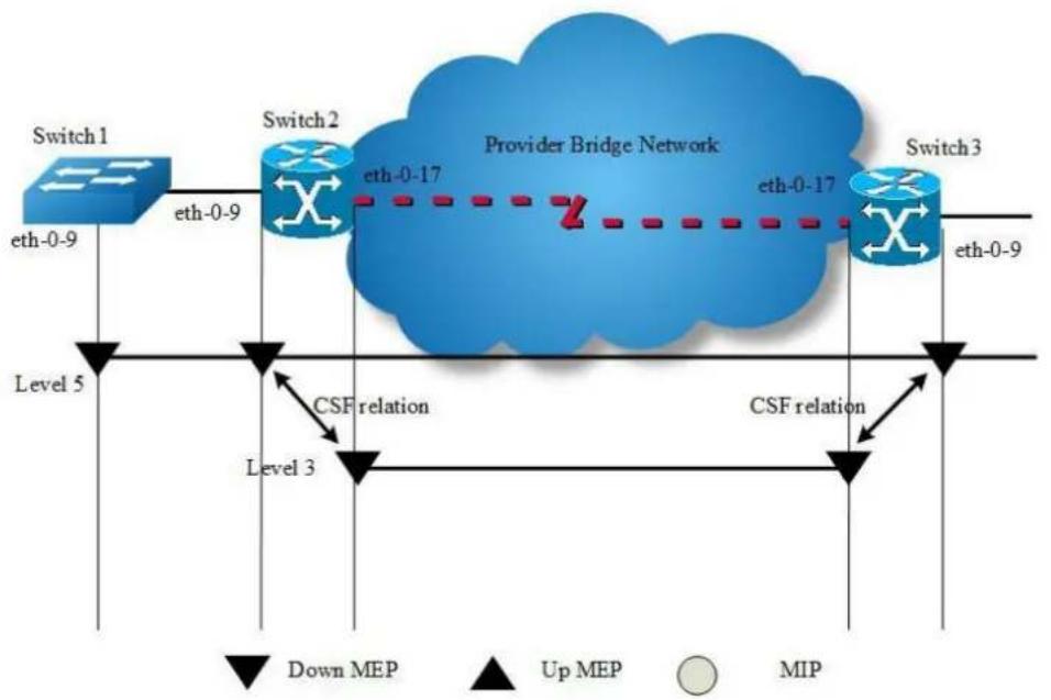
flowchart
graph TD
Switch1["Switch 1"] -->|eth-0-9| Switch2["Switch 2"]
Switch2 -->|eth-0-17| ProviderBridge["Provider Bridge Network"]
Switch3["Switch 3"] -->|eth-0-9| Switch2
Switch1 -->|Level 5| Level3["Level 3"]
Switch2 -->|CSF relation| Level3
Switch3 -->|CSF relation| Level3
Switch1 -->|Down MEP| Level3
Switch2 -->|Up MEP| Level3
Switch3 -->|MIP| Level3
Figure 16-7 CFM CSF
The following configuration should be operated on all switches if the switch ID is not specified.
step 1 Enter the configure mode
Switch# configure terminal
step 2 Enter the vlan configure mode and create the vlan
Configuring Switch1:
Switch(config)# vlan database
Switch(config vlan)# vlan 30
Switch(config vlan)# exit
Configuring Switch2 and Switch3:
Switch3(config)# vlan database
Switch3(config vlan)# vlan 20,30
Switch3(config vlan)# exit
step 3 Enable CFM globally and set cfm mode to y1731
Switch(config)# ethernet cfm enable
Switch(config)# ethernet cfm mode y1731
step 4 Create the cfm domain and bind the service with a vlan
Create a domain which has the name "cust" and level 5.
Switch(config)# ethernet cfm domain cust level 5
Switch(config-ether-cfm)# service cst vlan 30
Switch(config-ether-cfm)# exit
Create a domain which has the name "provid" and level 3.
Configuring Switch2 and Switch3:
Switch(config)# ethernet cfm domain provid level 3
Switch(config-ether-cfm)# service cst vlan 20
Switch(config-ether-cfm)# exit
step 5 Enter the interface configure mode and set the attributes of the interface
Interface configuration for Switch1:
Switch(config)# interface eth-0-9
Switch(config-if)# switchport mode trunk
Switch(config-if)# switchport trunk allowed vlan add 30
Switch(config-if)# ethernet cfm mep down mpid 66 domain cust vlan 30 interval 1
Switch(config-if)# ethernet cfm mep crosscheck mpid 99 domain cust vlan 30 mac d036.4567.8009
Switch(config-if)# no shutdown
Switch(config-if)# exit
Interface configuration for Switch2:
Switch(config)# interface eth-0-9
Switch(config-if)# switchport mode trunk
Switch(config-if)# switchport trunk allowed vlan add 30
Switch(config-if)# ethernet cfm mep down mpid 99 domain cust vlan 30 interval 1
Switch(config-if)# ethernet cfm mep crosscheck mpid 66 domain cust vlan 30 mac fa02.cdff.6a09
Switch(config-if)# no shutdown
Switch(config-if)# exit
Switch(config)#interface eth-0-17
Switch(config-if)# switchport mode trunk
Switch(config-if)# switchport trunk allowed vlan add 20
Switch(config-if)# ethernet cfm mep down mpid 666 domain provid vlan 20 interval 1
Switch(config-if)# no shutdown
Switch(config-if)# exit
Interface configuration for Switch3:
Switch(config)# interface eth-0-9
Switch(config-if)# switchport mode trunk
Switch(config-if)# switchport trunk allowed vlan add 30
Switch(config-if)# ethernet cfm mep down mpid 88 domain cust vlan 30 interval 1
Switch(config-if)# no shutdown
Switch(config-if)# exit
Switch(config)#interface eth-0-17
Switch(config-if)# switchport mode trunk
Switch(config-if)# switchport trunk allowed vlan add 20
Switch(config-if)# ethernet cfm mep down mpid 999 domain provid vlan 20 interval 1
Switch(config-if)# no shutdown
Switch(config-if)# exit
step 6 Enable continuity check
Switch(config)# ethernet cfm cc enable domain cust vlan 30
step 7 Configure csf relation between client mep and server mep
Configuring Switch2:
Switch(config)# ethernet cfm csf client domain cust vlan 30 mepid 99 server domain provid vlan 20 mepid 666 interval 1
Configuring Switch3:
Switch(config)# ethernet cfm csf client domain cust vlan 30 mepid 88 server domain provid vlan 20 mepid 999 interval 1
step 8 Validation
The following command is used to disable cc function in Switch1.
Switch (config)#no ethernet cfm cc enable domain cust vlan 30
For Switch2, client MEP 99 will report loc error and trigger csf for reason los, therefore server MEP 666 will send CSF packet in interval 1 second. The following command is used to display csf status for Swtich2.
Switch# show ethernet cfm csf
CTR-Client Trigger reason, L(los)/F(fdi)/R(rdi)/D(dci) or N/A
ECC-Enter CSF Condition, Y(Yes)/N(No)
SRR-Server Rx Reason, L(los)/F(fdi)/R(rdi)/D(dci) or N/A
Tx-I, Transmit Interval
Rx-I, The period which is gotten from CSF packets
Client Mep Server Mep
MPID Cli-Domain VLAN CTR ECC MPID Srv-Domain VLAN SRR Tx-I Rx-I
99 cust 30 L N 666 provid 20 N/A 1 N/A
For Switch3, server MEP 999 receives CSF packet and informs client MEP 99, then client MEP 88 will enter CSF condition. The following command is used to display csf status for Switch3:
Switch3# show ethernet cfm csf
CTR-Client Trigger reason, L(los)/F(fdi)/R(rdi)/D(dci) or N/A
ECC-Enter CSF Condition, Y(Yes)/N(No)
SRR-Server Rx Reason, L(los)/F(fdi)/R(rdi)/D(dci) or N/A
Tx-I, Transmit Interval
Rx-I, The period which is gotten from CSF packets
Client Mcp
MPID Cli-Domain VLAN CTR ECC MPID Srv-Domain VLAN SRR Tx-I Rx-I
88 cust 30 N/A Y 999 provid 20 L 1 1
Configure Dual-Ended LM
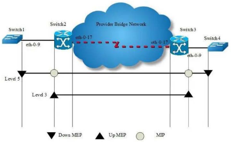
flowchart
graph LR
Switch1["Switch1"] -->|eth-0-9| Switch2["Switch2"]
Switch2 -->|eth-0-17| ProviderBridge["Provider Bridge Network"]
Switch2 -->|eth-0-17| Switch3["Switch3"]
Switch3 -->|eth-0-9| Switch4["Switch4"]
Switch1 -->|Level 5| Level3
Switch2 -->|Level 5| Level3
Switch3 -->|Level 5| Level3
Switch4 -->|Level 5| Level3
style ProviderBridge fill:#888,stroke:#333
style Switch1 fill:#fff,stroke:#333
style Switch2 fill:#fff,stroke:#333
style Switch3 fill:#fff,stroke:#333
style Switch4 fill:#fff,stroke:#333
Figure 16-8 CFM
step 1 Configuration prepare
Reference to the chapter "Configure CC/LB/LT/AIS/DM".
step 2 Configure Dual-Ended LM
Configuring Switch1:
Switch(config)# ethernet cfm lm enable dual-ended domain cust vlan 30 mepid 66 all-cos cache-size 10
Configuring Switch4:
Switch(config)# ethernet cfm lm enable dual-ended domain cust vlan 30 mepid 99 all-cos cache-size 10
step 3 Validation
The following command is used to display lm status for Switch1.
Switch# show ethernet cfm lm domain cust vlan 30 mepid 66
DOMAIN : cust
VLAN : 30
MEPID : 66
Start Time : 2013/07/16 1:36:56
End Time : 2013/07/16 1:37:07
Notes : 1. When the difference of Tx is less than the difference of Rx, the node is invalid, loss and loss ratio should be "-";
2. When loc is reported for mep, the loss should be "-" and loss ratio should be 100%;
3. When calculate average loss and loss ratio, invalid or loc nodes will be excluded;
Latest dual-ended loss statistics:
Index Cos Local-loss Local-loss ratio Remote-loss Remote-loss ratio Time
1 all 000.0000% 0 000.0000% 01:36:57
2 all 000.0000% 0 000.0000% 01:36:58
3 all 000.0000% 0 000.0000% 01:36:59
4 all 000.0000% 0 000.0000% 01:37:00
5 all 000.0000% 0 000.0000% 01:37:01
6 all 000.0000% 0 000.0000% 01:37:02
7 all 000.0000% 0 000.0000% 01:37:03
8 all 000.0000% 0 000.0000% 01:37:04
9 all 000.0000% 0 000.0000% 01:37:05
10 all 000.0000% 0 000.0000% 01:37:07
Maximum Local-loss : 0 Maximum Local-loss Ratio : 000.0000%
Minimum Local-loss : 0 Minimum Local-loss Ratio : 000.0000%
Average Local-loss : 0 Average Local-loss Ratio : 000.0000%
Maximum Remote-loss : 0 Maximum Remote-loss Ratio : 000.0000%
Minimum Remote-loss : 0 Minimum Remote-loss Ratio : 000.0000%
Average Remote-loss : 0 Average Remote-loss Ratio : 000.000
The following command is used to display lm status for Switch4.
Switch# show ethernet cfm lm domain cust vlan 30 mepid 99
DOMAIN : cust
VLAN : 30
MEPID : 99
Start Time : 2013/07/16 1:37:11
End Time : 2013/07/16 1:37:22
Notes : 1. When the difference of Tx is less than the difference of Rx, the node is invalid, loss and loss ratio should be "-"";
2. When loc is reported for mep, the loss should be "-" and loss
ratio should be 100%;
3. When calculate average loss and loss ratio, invalid or loc nodes will be excluded;
Latest dual-ended loss statistics:
Index Cos Local-loss Local-loss ratio Remote-loss Remote-loss ratio Time
| 1 all | 000.0000% | 0 | 000.0000% | 01:37:12 |
| 2 all | 000.0000% | 0 | 000.0000% | 01:37:13 |
| 3 all | 000.0000% | 0 | 000.0000% | 01:37:14 |
| 4 all | 000.0000% | 0 | 000.0000% | 01:37:16 |
| 5 all | 000.0000% | 0 | 000.0000% | 01:37:17 |
| 6 all | 000.0000% | 0 | 000.0000% | 01:37:18 |
| 7 all | 000.0000% | 0 | 000.0000% | 01:37:19 |
| 8 all | 000.0000% | 0 | 000.0000% | 01:37:20 |
| 9 all | 000.0000% | 0 | 000.0000% | 01:37:21 |
| 10 all | 000.0000% | 0 | 000.0000% | 01:37:22 |
| Maximum Local-loss : 0 | Maximum Local-loss Ratio : 000.0000% |
| Minimum Local-loss : 0 | Minimum Local-loss Ratio : 000.0000% |
| Average Local-loss : 0 | Average Local-loss Ratio : 000.0000% |
| Maximum Remote-loss : 0 | Maximum Remote-loss Ratio : 000.0000% |
| Minimum Remote-loss : 0 | Minimum Remote-loss Ratio : 000.0000% |
| Average Remote-loss : 0 | Average Remote-loss Ratio : 000.0000% |
Configure Single-Ended LM
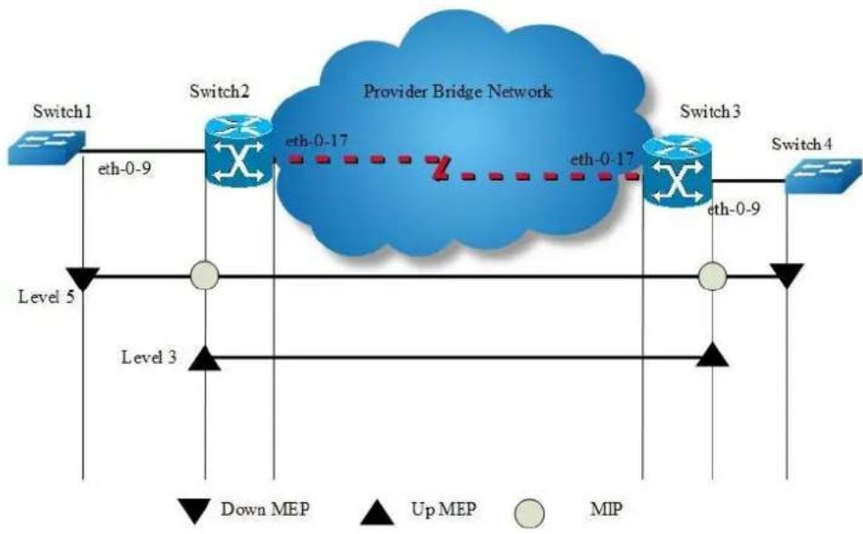
flowchart
graph LR
Switch1["Switch1"] -->|eth-0-9| Switch2["Switch2"]
Switch2 -->|eth-0-17| ProviderBridge["Provider Bridge Network"]
Switch2 -->|Z| Switch3["Switch3"]
Switch3 -->|eth-0-9| Switch4["Switch4"]
Switch1 -->|Level 5| Level3
Switch2 -->|Level 5| Level3
Switch3 -->|Level 5| Level3
Switch4 -->|Level 5| Level3
style ProviderBridge fill:#f9f,stroke:#333
style Switch1 fill:#ccf,stroke:#333
style Switch2 fill:#cfc,stroke:#333
style Switch3 fill:#fcc,stroke:#333
style Switch4 fill:#cff,stroke:#333
Figure 16-9 CFM
step 1 Configuration prepare
Reference to the chapter "Configure CC/LB/LT/AIS/DM".
step 2 Configure Single-Ended LM
Configuring Switch1:
Switch(config)# ethernet cfm lm enable single-ended domain cust vlan 30 mepid 66 all-cos
Configuring Switch4:
Switch(config)# ethernet cfm lm enable single-ended domain cust vlan 30 mepid 99 all-cos
step 3 Validation
The following command is used to output lmm and display lm results for Switch1.
Switch# ethernet cfm lm single-ended domain cust vlan 30 rmepid 99 mepid 66 count
10
DOMAIN : cust
VLAN : 30
MEPID : 66
Start Time : 2013/07/16 1:39:38
End Time : 2013/07/16 1:39:38
Notes : 1. When the difference of Tx is less than the difference of Rx, the node is invalid, loss and loss ratio should be "-";
2. When loc is reported for mep, the loss should be "-" and loss ratio should be 100%;
3. When calculate average loss and loss ratio, invalid or loc nodes will be excluded;
Latest single-ended loss statistics:
Index Cos Local-loss Local-loss ratio Remote-loss Remote-loss ratio
1 all 000.0000% 0 000.0000%
2 all 000.0000% 0 000.0000%
3 all 000.0000% 0 000.0000%
4 all 000.0000% 0 000.0000%
5 all 000.0000% 0 000.0000%
6 all 000.0000% 0 000.0000%
7 all 000.0000% 0 000.0000%
8 all 000.0000% 0 000.0000%
9 all 000.0000% 0 000.0000%
Maximum Local-loss : 0 Maximum Local-loss Ratio : 000.0000%
Minimum Local-loss : 0 Minimum Local-loss Ratio : 000.0000%
Average Local-loss : 0 Average Local-loss Ratio : 000.0000%
Maximum Remote-loss : 0 Maximum Remote-loss Ratio : 000.0000%
Minimum Remote-loss : 0 Minimum Remote-loss Ratio : 000.0000%
Average Remote-loss : 0 Average Remote-loss Ratio : 000.0000%
Configure Test
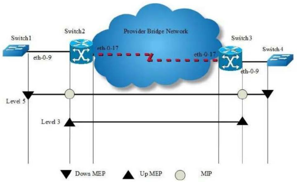
flowchart
graph LR
Switch1["Switch1"] -->|eth-0-9| Switch2["Switch2"]
Switch2 -->|eth-0-17| ProviderBridge["Provider Bridge Network"]
Switch2 -->|Z| Switch3["Switch3"]
Switch3 -->|eth-0-9| Switch4["Switch4"]
Switch3 -->|eth-0-17| Switch2
Switch2 -->|Level 5| Level3["Level 3"]
Switch3 -->|Level 5| Level3
Switch4 -->|Down MEP| Level3
Switch4 -->|Up MEP| Level3
Switch4 -->|MIP| Level3
Figure 16-10 CFM
step 1 Configuration prepare
Reference to the chapter "Configure CC/LB/LT/AIS/DM".
step 2 Configure Test
Configure test transmission enable on Switch1:
Switch(config)# ethernet cfm tst transmission enable domain cust vlan 30 mep 66 tx-mode continuous pattern-type random packet-size 6
Configure test reception enable on Switch4:
Switch(config)# ethernet cfm tst reception enable domain cust vlan 30 mep 99
step 3 Validation
The following command is used to start test transmission on Switch1.
Switch# ethernet cfm tst start rate 1000 time second 1
The following command is used to display test information on Switch1.
Switch# show ethernet cfm tst
DOMAIN : cust
VLAN : 30
MEPID : 66
Transmission : Enabled
Reception : Disabled
Status : Non-Running
Start Time : 06:32:48
Predict End Time : 06:33:18
Actual End Time : 06:33:18
Packet Type : TST
Rate : 1000 mbps
Packet Size : 64 bytes
Tx Number : 29
Tx Bytes : 1856
Rx Number : 0
Rx Bytes : 0
The following command is used to display test information on Switch4.
16.4 Configuring CPU Traffic
16.4.1 Overview
Function Introduction
CPU traffic limit is a useful mechanism for protecting CPU from malicious flows by injecting huge volume of PDUs into switches.
CPU traffic limit provides two-level protection for CPU.
The low-level traffic limit is performed for each reason, which is realized by queue shaping of each type of PDU.
The high-level traffic limit is performed for all reasons, which is realized by channel shaping at CPU channel.
With this two-level protection, each PDU-to-CPU rate is limited and the overall PDU-to-CPU rate is also limited.

NOTE
: The word “reason”, means this type of packets will be sent to cpu for further processing.
The description of all reason is as following.
| Reason | Description |
| arp | Address Resolution Protocol |
| bpdu | Bridge Protocol Data Unit |
| dhcp | Dynamic Host Configuration Protocol |
| eapol | Extensible Authentication Protocol Over Lan |
| erps | Ethernet Ring Protection Switching |
| fwd-to-cpu | Packets forwarding to cpu |
| icmp-redirect | ICMP Redirect |
| igmp | IGMP Snooping Protocol |
| ip-option | Packets with IP Option |
| ipda | IP Destination to Router-self |
| ssh | SSH protocol packet |
| telnet | Telnet protocol packet |
| mlag | MLAG protocol packet |
| tcp | TCP protocol packet |
| ldp | Label Distribution Protocol |
| macsa-mismatch | Port Security for source mac learned |
| mcast-rpf-fail | Multicast with rpf fail or first multicast packet |
| mpls-ttl-fail | Mpls Packets with ttl fail |
| ip-mtu-fail | IP packet with mtu fail |
| ospf | Open Shortest Path First |
| pim | Protocol Independent Multicast |
| port-security-discard | Port Security for exceeding fdb maxnum |
| rip | Routing Information Protocol |
| sflow-egress | Sampled flow at egress direction |
| sflow-ingress | Sampled flow at ingress direction |
| slow-protocol | Slow Protocol (including EFM, LACP and SYNCE) |
| smart-link | Smart Link Protocol |
| ucast-ttl-fail | Unicast Packets with ttl fail |
| udld | Unidirectional Link Detection Protocol |
| vlan-security-discard | Vlan Security for exceeding fdb maxnum |
| vrrp | Virtual Router Redundancy Protocol |
| bfd-learning | BFD learning packets |
| dot1x-mac-bypass | Mac auth bypass packets |
| bgp | Border gateway protocol packet |
| egress-ttl-fail | Egress ttl fail packet |
| icmpv6 | ICMPv6 packet |
| l2protocol-tunnel | Layer2 protocol tunnel packet |
| loopback-detection | ILoopback detection packet |
| mirror-to-cpu | Mirror to cpu packet |
| ndp | Neighbor discovery protocol packet |
| tunnel-gre-keepalive | Tunnel gre keepalive reply packet |
The default rate and class configuration for all reason is as following.
| reason | rate(pps) | class |
| arp | 256 | 1 |
| bpdu | 64 | 3 |
| dhcp | 128 | 0 |
| eapol | 128 | 0 |
| erps | 128 | 3 |
| fwd-to-cpu | 64 | 0 |
| icmp-redirect | 128 | 0 |
| igmp | 128 | 2 |
| ip-option | 512 | 0 |
| ipda | 1000 | 0 |
| ssh | 64 | 3 |
| telnet | 64 | 3 |
| mlag | 1000 | 1 |
| tcp | 64 | 2 |
| ldp | 512 | 1 |
| macsa-mismatch | 128 | 0 |
| mcast-rpf-fail | 128 | 1 |
| mpls-ttl-fail | 64 | 0 |
| ip-mtu-fail | 64 | 0 |
| ospf | 256 | 1 |
| pim | 128 | 1 |
| port-security-discard | 128 | 0 |
| rip | 64 | 1 |
| sflow-egress | 128 | 0 |
| sflow-ingress | 128 | 0 |
| slow-protocol | 256 | 1 |
| smart-link | 128 | 2 |
| ucast-ttl-fail | 64 | 0 |
| udld | 128 | 3 |
| vlan-security-discard | 128 | 0 |
| vrrp | 512 | 1 |
| bfd-learning | 128 | 1 |
| dot1x-mac-bypass | 64 | 2 |
| bgp | 256 | 1 |
| egress-ttl-fail | 64 | 0 |
| icmpv6 | 64 | 2 |
| l2protocol-tunnel | 1000 | 0 |
| loopback-detection | 64 | 3 |
| mirror-to-cpu | 1000 | 0 |
| ndp | 64 | 2 |
| tunnel-gre-keepalive | 64 | 0 |
Principle Description
Terminology
PDU: Protocol Data Unit
16.4.2 Configuration
step 1 Enter the configure mode
Switch# configure terminal
step 2 Set the total rate
The default value of total rate is 2000, the unit is pps (packet-per-second)
Switch(config)# cpu-traffic-limit total rate 3000
step 3 Set the saparate rate
Use RIP packets for example:
Switch(config)# cpu-traffic-limit reason rip rate 500
step 4 Set the reason class
Switch(config)# cpu-traffic-limit reason rip class 3

NOTE
The valid range of reason class is 0-3. The larger number indicates the higher priority.
step 5 Exit the configure mode
Switch(config)# end
step 6 Validation
To display the CPU Traffic Limit configuration, use following privileged EXEC commands.
Switch# show cpu traffic-limit
reason rate (pps) class
dotlx-mac-bypass 64 2
bpdu 64 3
slow-protocol 256 1
eapol 128 0
erps 128 3
smart-link 128 2
udld 128 3
loopback-detection 64 3
arp 256 1
dhcp 128 0
rip 500 3
ldp 512 1
ospf 256 1
pim 128 1
bgp 256 1
vrrp 512 1
ndp 64 2
icmpv6 64 2
ssh 64 3
telnet 64 3
mlag 1000 1
tcp 64 2
ipda 1000 0
icmp-redirect 128 0
mcast-rpf-fail 128 1
macsa-mismatch 128 0
port-security-discard 128 0
vlan-security-discard 128 0
egress-ttl-fail 64 0
ip-mtu-fail 64 0
bfd-learning 128 1
ptp 512 2
ip-option 512 0
tunnel-gre-keepalive 64 0
ucast-ttl-fail 64 0
mpls-ttl-fail 64 0
igmp 128 2
sflow-ingress 128 0
sflow-egress 128 0
fwd-to-cpu 64 0
l2protocol-tunnel 1000 0
mirror-to-cpu 1000 0
Total rate: 3000 (pps)
To display the CPU Traffic statistics information, use following privileged EXEC commands.
Switch# show cpu traffic-statistics receive all statistics rate time is 5 second(s)
reason count(packets) rate(pps)
dot1x-mac-bypass 0 0
bpdu 0 0
slow-protocol 0 0
eapol 0 0
erps 0 0
smart-link 0 0
udld 0 0
loopback-detection 0 0
arp 0 0
dhcp 0 0
rip 0 0
ldp 0 0
ospf 0 0
pim 0 0
bgp 0 0
vrrp 0 0
rsvp 0 0
ndp 0 0
icmpv6 0 0
ssh 0 0
telnet 0 0
mlag 0 0
tcp 0 0
ipda 0 0
icmp-redirect 0 0
mcast-rpf-fail 0 0
macsa-mismatch 0 0
port-security-discard 0 0
vlan-security-discard 0 0
egress-ttl-fail 0 0
ip-mtu-fail 0 0
bfd-learning 0 0
ptp 0 0
ip-option 0 0
tunnel-gre-keepalive 0 0
ucast-ttl-fail 0 0
mpls-ttl-fail 0 0
igmp 0 0
sflow-ingress 0 0
sflow-egress 0 0
fwd-to-cpu 0 0
l2protocol-tunnel 0 0
mirror-to-cpu 0 0
mpls-tp-pwoam 0 0
other 0 0
Total 0 0
16.4.3 Application cases
N/A
16.5 Configuring G.8031
16.5.1 Overview
Function Introduction
This document describes the configuration of G.8031 Ethernet Linear Protection Switching.
The goal of linear protection switching mechanism is to satisfy the requirement of fast protection switching for ethernet network. Linear protection switching means that, for one or more working transport entities, there is one protection transport entity, which is disjoint from any of working transport entities, ready for taking over the service transmission when a working transport entity failed.
To guarantee the protection switching time, for a working transport entity, its protection transport entity is always pre-configured before the failure occurs. Normally, the normal traffic will be transmitted and received on the working transport entity. The switching to protection transport entity is usually triggered by link/node failure, external commands, etc. Note that external commands are often used in transport network by operators, and they are very useful in cases of service adjustment, path maintenance, etc.
Principle Description
Reference: ITU-T G.8031/Y.1342 (06/2006)
16.5.2 Configuration

flowchart
graph LR
A["Switch1"] -->|eth-0-9| B["Working Transport Entity"]
B -->|eth-0-9| C["Switch2"]
A -->|eth-0-10| D["Protection Transport Entity"]
D -->|eth-0-10| C
Figure 16-11 G.8031
The following configuration should be operated on all switches if the switch ID is not specified.
step 1 Enter the configure mode
Switch# configure terminal
step 2 Enter the vlan configure mode and create the vlan
Switch(config)# vlan database Switch(config-vlan)# vlan 10-20 Switch(config-vlan)# exit
step 3 Set the spanning tree mode and create mstp instance
Switch(config)# spanning-tree mode mstp
Switch(config)# spanning-tree mst configuration
Switch(config-mst)# instance 10 vlan 10-20
Switch(config-mst)# exit
step 4 Enable cfm globally, create cfm domain and bind the vlan, enable continuity check
Switch1(config)#ethernet cfm enable
Switch1(config)#ethernet cfm domain test level 5
Switch1(config-ether-cfm)#service test1 vlan 10
Switch1(config-ether-cfm)#service test2 vlan 11
Switch1(config-ether-cfm)#exit
Switch1(config)#ethernet cfm cc enable domain test vlan 10
Switch1(config)#ethernet cfm cc enable domain test vlan 11
step 5 Enter the interface configure mode and set the attributes of the interface
Interface configuration for Switch1:
Switch(config)# interface eth-0-9
Switch(config-if)# switchport mode trunk
Switch(config-if)# switchport trunk allowed vlan add 10-20
Switch(config-if)# ethernet cfm mep down mpid 10 domain test vlan 10 interval 1
Switch(config-if)# ethernet cfm mep crosscheck mpid 12 domain test vlan 10 mac bab3.08a4.c709
Switch(config-if)# spanning-tree port disable
Switch(config-if)# no shutdown
Switch(config-if)# exit
Switch(config)# interface eth-0-10
Switch(config-if)# switchport mode trunk
Switch(config-if)# switchport trunk allowed vlan add 10-20
Switch(config-if)# ethernet cfm mep down mpid 11 domain test vlan 11 interval 1
Switch(config-if)# ethernet cfm mep crosscheck mpid 13 domain test vlan 11 mac bab3.08a4.c70a
Switch(config-if)# spanning-tree port disable
Switch(config-if)# no shutdown
Switch(config-if)# exit
Interface configuration for Switch2:
Switch(config)# interface eth-0-9
Switch(config-if)# switchport mode trunk
Switch(config-if)# switchport trunk allowed vlan add 10-20
Switch(config-if)# ethernet cfm mep down mpid 12 domain test vlan 10 interval 1
Switch(config-if)# ethernet cfm mep crosscheck mpid 10 domain test vlan 10 mac bab3.08a4.c809
Switch(config-if)# spanning-tree port disable
Switch(config-if)# exit
Switch(config)# interface eth-0-10
Switch(config-if)# switchport mode trunk
Switch(config-if)# switchport trunk allowed vlan add 10-20
Switch(config-if)# ethernet cfm mep down mpid 13 domain test vlan 11 interval 1
Switch(config-if)# ethernet cfm mep crosscheck mpid 11 domain test vlan 11 mac bab3.08a4.c80a
Switch(config-if)# spanning-tree port disable
Switch(config-if)# exit
step 6 Create G8031 group and bind the mstp instance
Switch(config)# g8031 eps-id 10 working-port eth-0-9 protection-port eth-0-10
Switch(g8031-config-switching)# domain test working-service test1 protection-service test2
Switch(g8031-config-switching)# instance 10
Switch(config-if)# exit
step 7 Exit the configure mode
Switch(config)# end
step 8 Validation
Display the result on Switch1.
Switch# show g8031
Codes: ID - Group id of G.8031
IF-W - Interface of working entity, IF-P - Interface of protection entity
MD - Maintenance domain
MA-W - Maintenance association of working entity
MA-W - Maintenance association of protection entity
CS - Current state, LS - Last state, LE - Last event, FS - Far end state
R/B - Request signal & bridged signal, MODE - Revertive or Non-revertive
WTR - Wait to restore, DFOP - Failure of protocol defects
ID IF-W IF-P MD MA-W MA-P CS LS LE FS R/B MODE
10 eth-0-9 eth-0-10 test test1 test2 NR NR NR null REV
APS Vid - 11
Active-Path - Working
DFOP State - Not in defect mode
Protected Instance - 10
Display the result on Switch2.
Switch# show g8031
Codes: ID - Group id of G.8031
IF-W - Interface of working entity, IF-P - Interface of protection entity
MD - Maintenance domain
MA-W - Maintenance association of working entity
MA-W - Maintenance association of protection entity
CS - Current state, LS - Last state, LE - Last event, FS - Far end state
R/B - Request signal & bridged signal, MODE - Revertive or Non-revertive
WTR - Wait to restore, DFOP - Failure of protocol defects
ID IF-W IF-P MD MA-W MA-P CS LS LE FS R/B MODE
10 eth-0-9 eth-0-10 test test1 test2 NR NR NR NR null REV
APS Vid - 11
Active-Path - Working
DFOP State - Not in defect mode
Protected Instance - 10
16.5.3 Application cases
N/A
16.6 Configuring G8032
16.6.1 Overview
Ethernet rings can provide wide-area multipoint connectivity more economically due to their reduced number of links. Each ring node is connected to adjacent nodes participating in the same ring, using two independent links. A ring link is bounded by two adjacent nodes and a port for a ring link is called a ring port. The minimum number of nodes on a ring is two.
The fundamentals of this ring protection switching architecture are:
The principle of loop avoidance
The utilization of learning, forwarding, and address table mechanisms defined in the Ethernet flow forwarding function (ETH_FF).
Loop avoidance in the ring is achieved by guaranteeing that, at any time, traffic may flow on all but one of the ring links. This particular link is called the ring protection link (RPL), and under normal conditions this link is blocked, i.e., not used for traffic. One designated node, the RPL owner, is responsible to block traffic over the RPL. Under a ring failure condition, the RPL owner is responsible to unblock the RPL, allowing the RPL to be used for traffic.
The event of a ring failure results in protection switching of the traffic. This is achieved under the control of the ETH_FF functions on all ring nodes.
An APS protocol is used to coordinate the protection actions over the ring.
Function Introduction
N/A
Principle Description
- Reference:
- T-REC-G.8032-200806-I!!PDF-E.pdf
- T-REC-G.8032-201003-I!!PDF-E.pdf
- T-REC-G.8032-201708-I!Cor1!PDF-E.pdf
16.6.2 Topology
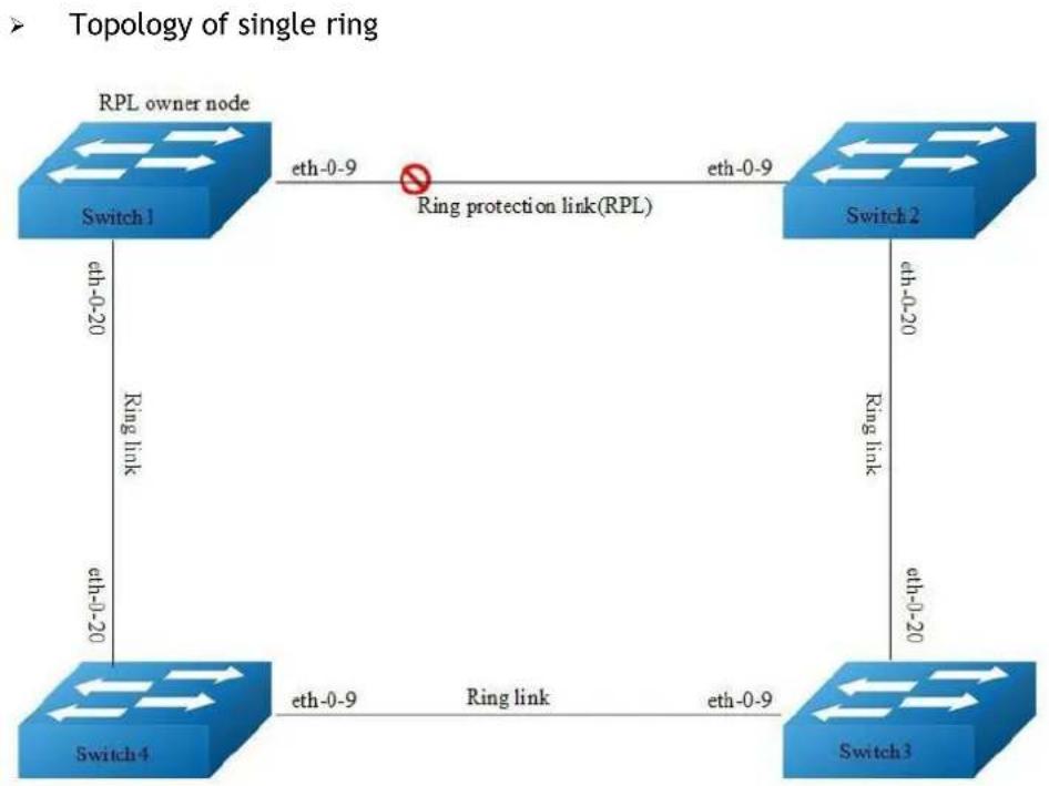
flowchart
graph TD
A["RPL owner node"] -->|eth-0-9| B["Ring protection link(RPL)"]
B -->|eth-0-9| C["Switch 2"]
C -->|eth-0-20| D["Switch 3"]
D -->|eth-0-20| E["Switch 4"]
E -->|eth-0-9| A
style B stroke:#ff0000,stroke-width:2px
Figure 16-12 Topology of single G8032 ring
Topology of multiple rings
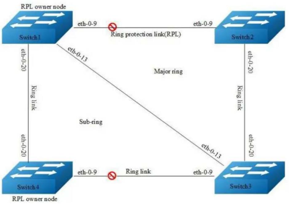
flowchart
graph TD
A["RPL owner node"] -->|eth-0-9| B["Switch1"]
B -->|eth-0-13| C["Switch2"]
C -->|eth-0-20| D["Switch3"]
D -->|eth-0-20| E["Switch4"]
E -->|eth-0-9| F["RPL owner node"]
F -->|eth-0-20| G["Switch1"]
G -->|Ring link| H["Switch4"]
H -->|Ring link| I["Switch3"]
I -->|Ring link| J["Switch2"]
J -->|Ring protection link(RPL)| K["Switch1"]
K -->|Ring protection link(RPL)| L["Switch2"]
L -->|Ring protection link(RPL)| M["Switch3"]
M -->|Ring protection link(RPL)| N["Switch4"]
N -->|Ring protection link(RPL)| O["Switch1"]
O -->|Ring protection link(RPL)| P["Switch2"]
P -->|Ring protection link(RPL)| Q["Switch3"]
Q -->|Ring protection link(RPL)| R["Switch4"]
R -->|Ring protection link(RPL)| S["Switch1"]
S -->|Ring protection link(RPL)| T["Switch2"]
T -->|Ring protection link(RPL)| U["Switch3"]
U -->|Ring protection link(RPL)| V["Switch4"]
V -->|Ring protection link(RPL)| W["Switch1"]
W -->|Ring protection link(RPL)| X["Switch2"]
X -->|Ring protection link(RPL)| Y["Switch3"]
Y -->|Ring protection link(RPL)| Z["Switch4"]
Z -->|Ring protection link(RPL)| AA["Switch1"]
AA -->|Ring protection link(RPL)| AB["Switch2"]
AB -->|Ring protection link(RPL)| AC["Switch3"]
AC -->|Ring protection link(RPL)| AD["Switch4"]
AD -->|Ring protection link(RPL)| AE["Switch1"]
AE -->|Ring protection link(RPL)| AF["Switch2"]
AF -->|Ring protection link(RPL)| AG["Switch3"]
AG -->|Ring protection link(RPL)| AH["Switch4"]
AH -->|Ring protection link(RPL)| AI["Switch1"]
AI -->|Ring protection link(RPL)| AJ["Switch2"]
AJ -->|Ring protection link(RPL)| AK["Switch3"]
AK -->|Ring protection link(RPL)| AL["Switch4"]
AL -->|Ring protection link(RPL)| AM["Switch1"]
AM -->|Ring protection link(RPL)| AN["Switch2"]
AN -->|Ring protection link(RPL)| AO["Switch3"]
AO -->|Ring protection link(RPL)| AP["Switch4"]
AP -->|Ring protection link(RPL)| AQ["Switch1"]
AQ -->|Ring protection link(RPL)| AR["Switch2"]
AR -->|Ring protection link(RPL)| AS["Switch3"]
AS -->|Ring protection link(RPL)| AT["Switch4"]
Figure 16-13 Topology of multiple G8032 rings
16.6.3 Configuration of single ring
step 1 Configuration of Switch1
Switch# configure terminal
Enter configuration commands, one per line. End with CNTL/Z.
Switch(config)# vlan database
Switch(config-vlan)# vlan 10-100
Switch(config-vlan)# exit
Switch(config)# spanning-tree mode mstp
Switch(config)# spanning-tree mst configuration
Switch(config-mst)# instance 1 vlan 10-99
Switch(config-mst)# exit
Switch(config)# no ip igmp snooping vlan 100
Switch(config)# interface eth-0-9
Switch(config-if)# switchport mode trunk
Switch(config-if)# switchport trunk allowed vlan add 10-100
Switch(config-if)# spanning-tree port disable
Switch(config-if)# no shutdown
Switch(config-if)# exit
Switch(config)# interface eth-0-20
Switch(config-if)# switchport mode trunk
Switch(config-if)# switchport trunk allowed vlan add 10-100
Switch(config-if)# spanning-tree port disable
Switch(config-if)# no shutdown
Switch(config-if)# exit
Switch(config)# g8032 ring-id 1 east-interface eth-0-9 west-interface eth-0-20
Switch(g8032-config-switch)# rpl owner east-interface
Switch(g8032-config-switch)# instance 1
Switch(g8032-config-switch)# control-vlan 100
Switch(g8032-config-switch)# ring enable
step 2 Switch1 validation
Switch# show g8032
RingID MajorRing State East Status West Status
1 N/A Pending eth-0-9 Blocked eth-0-20 Forward
Control Vlan : 100
Is Enabled : Yes
Mode : Revertive
Node Role : Owner
Is Sub_ring : No
Protect Instance : 1
RPL : east-interface
Wait-to-restore : 04:26 (266492 msecs)
Hold-off Timer : 0 (msecs)
Guard Timer : 500 (msecs)
WTB Timer : 5500 (msecs)
RAPS MEL : 7
Is Forward-to-cpu : 1
step 3 Configuration of Switch2
Switch# configure terminal
Enter configuration commands, one per line. End with CNTL/Z.
Switch(config)# vlan database
Switch(config-vlan)# vlan 10-100
Switch(config-vlan)# exit
Switch(config)# spanning-tree mode mstp
Switch(config)# spanning-tree mst configuration
Switch(config-mst)# instance 1 vlan 10-99
Switch(config-mst)# exit
Switch(config)# no ip igmp snooping vlan 100
Switch(config)# interface eth-0-9
Switch(config-if)# switchport mode trunk
Switch(config-if)# switchport trunk allowed vlan add 10-100
Switch(config-if)# spanning-tree port disable
Switch(config-if)# no shutdown
Switch(config-if)# exit
Switch(config)# interface eth-0-20
Switch(config-if)# switchport mode trunk
Switch(config-if)# switchport trunk allowed vlan add 10-100
Switch(config-if)# spanning-tree port disable
Switch(config-if)# no shutdown
Switch(config-if)# exit
Switch(config)# g8032 ring-id 1 east-interface eth-0-9 west-interface eth-0-20
Switch(g8032-config-switch)# instance 1
Switch(g8032-config-switch)# control-vlan 100
Switch(g8032-config-switch)# ring enable
step 4 Switch2 validation
Switch# show g8032
RingID MajorRing State East Status West Status
1 N/A Pending eth-0-9 Blocked eth-0-20 Forward
Control Vlan : 100
Is Enabled : Yes
Mode : Revertive
Node Role : N/A
Is Sub_ring : No
Protect Instance : 1
Wait-to-restore : 05:00
Hold-off Timer : 0 (msecs)
Guard Timer : 500 (msecs)
WTB Timer : 5500 (msecs)
RAPS MEL : 7
Is Forward-to-cpu : 1
step 5 Configuration of Switch3
Switch# configure terminal
Enter configuration commands, one per line. End with CNTL/Z.
Switch(config)# vlan database
Switch(config-vlan)# vlan 10-100
Switch(config-vlan)# exit
Switch(config)# spanning-tree mode mstp
Switch(config)# spanning-tree mst configuration
Switch(config-mst)# instance 1 vlan 10-99
Switch(config-mst)# exit
Switch(config)# no ip igmp snooping vlan 100
Switch(config)# interface eth-0-9
Switch(config-if)# switchport mode trunk
Switch(config-if)# switchport trunk allowed vlan add 10-100
Switch(config-if)# spanning-tree port disable
Switch(config-if)# no shutdown
Switch(config-if)# exit
Switch(config)# interface eth-0-20
Switch(config-if)# switchport mode trunk
Switch(config-if)# switchport trunk allowed vlan add 10-100
Switch(config-if)# spanning-tree port disable
Switch(config-if)# no shutdown
Switch(config-if)# exit
Switch(config)# g8032 ring-id 1 east-interface eth-0-9 west-interface eth-0-20
Switch(g8032-config-switch)# instance 1
Switch(g8032-config-switch)# control-vlan 100
Switch(g8032-config-switch)# ring enable
step 6 Switch3 validation
Switch# show g8032
| RingID | MajorRing | State | East | Status | West | Status |
| 1 | N/A | Pending | eth-0-9 | Blocked | eth-0-20 | Forward |
| Control Vlan | : 100 | |||||
| Is Enabled | : Yes | |||||
| Mode | : Revertive | |||||
| Node Role | : N/A | |||||
| Is Sub_ring | : No | |||||
| Protect Instance | : 1 | |||||
| Wait-to-restore | : 05:00 | |||||
| Hold-off Timer | : 0 (msecs) | |||||
| Guard Timer | : 500 (msecs) | |||||
| WTB Timer | : 5500 (msecs) | |||||
| RAPS MEL | : 7 | |||||
| Is Forward-to-cpu | : 1 | |||||
step 7 Configuration of Switch4
Switch# configure terminal
Enter configuration commands, one per line. End with CNTL/Z.
Switch(config)# vlan database
Switch(config-vlan)# vlan 10-100
Switch(config-vlan)# exit
Switch(config)# spanning-tree mode mstp
Switch(config)# spanning-tree mst configuration
Switch(config-mst)# instance 1 vlan 10-99
Switch(config-mst)# exit
Switch(config)# no ip igmp snooping vlan 100
Switch(config)# interface eth-0-9
Switch(config-if)# switchport mode trunk
Switch(config-if)# switchport trunk allowed vlan add 10-100
Switch(config-if)# spanning-tree port disable
Switch(config-if)# no shutdown
Switch(config-if)# exit
Switch(config)# interface eth-0-20
Switch(config-if)# switchport mode trunk
Switch(config-if)# switchport trunk allowed vlan add 10-100
Switch(config-if)# spanning-tree port disable
Switch(config-if)# no shutdown
Switch(config-if)# exit
Switch(config)# g8032 ring-id 1 east-interface eth-0-9 west-interface eth-0-20
Switch(g8032-config-switch)# instance 1
Switch(g8032-config-switch)# control-vlan 100
Switch(g8032-config-switch)# ring enable
step Switch4 validation
| Switch# show g8032 | ||||||
| RingID | MajorRing | State | East | Status | West | Status |
| 1 N/A | Pending | eth-0-9 | Blocked | eth-0-20 | Forward | |
Control Vlan : 100
Is Enabled : Yes
Mode : Revertive
Node Role : N/A
Is Sub_ring : No
Protect Instance : 1
Wait-to-restore : 05:00
Hold-off Timer : 0 (msecs)
Guard Timer : 500 (msecs)
WTB Timer : 5500 (msecs)
RAPS MEL : 7
Is Forward-to-cpu : 1
16.6.4 Configuration of multiple rings - Non-virtual-channel
step 1 Configuration of Switch1
Switch# configure terminal
Enter configuration commands, one per line. End with CNTL/Z.
Switch(config)# vlan database
Switch(config-vlan)# vlan 10-150
Switch(config-vlan)# exit
Switch(config)# spanning-tree mode mstp
Switch(config)# spanning-tree mst configuration
Switch(config-mst)# instance 1 vlan 10-99
Switch(config-mst)# instance 2 vlan 101-150
Switch(config-mst)# exit
Switch(config)# no ip igmp snooping vlan 100
Switch(config)# no ip igmp snooping vlan 20
Switch(config)# interface eth-0-9
Switch(config-if)# switchport mode trunk
Switch(config-if)# switchport trunk allowed vlan add 10-150
Switch(config-if)# spanning-tree port disable
Switch(config-if)# no shutdown
Switch(config-if)# exit
Switch(config)# interface eth-0-13
Switch(config-if)# switchport mode trunk
Switch(config-if)# switchport trunk allowed vlan add 10-150
Switch(config-if)# spanning-tree port disable
Switch(config-if)# no shutdown
Switch(config-if)# exit
Switch(config)# interface eth-0-20
Switch(config-if)# switchport mode trunk
Switch(config-if)# switchport trunk allowed vlan add 101-150
Switch(config-if)# switchport trunk allowed vlan add 20
Switch(config-if)# spanning-tree port disable
Switch(config-if)# no shutdown
Switch(config-if)# exit
Switch(config)# g8032 ring-id 1 east-interface eth-0-9 west-interface eth-0-13
Switch(g8032-config-switch)# rpl owner east-interface
Switch(g8032-config-switch)# instance 1
Switch(g8032-config-switch)# instance 2
Switch(g8032-config-switch)# control-vlan 100
Switch(g8032-config-switch)# ring enable
Switch(g8032-config-switch)# exit
Switch(config)# g8032 ring-id 2 interface eth-0-20 major-ring-id 1
Switch(g8032-config-switch)# instance 2
Switch(g8032-config-switch)# control-vlan 20
Switch(g8032-config-switch)# ring enable
step 2 Switch1 validation
| Switch# show g8032 | |||||
| RingID MajorRing State East Status West Status | |||||
| 1 N/A | Pending | eth-0-9 | Blocked | eth-0-13 | Forward |
| Control Vlan | : 100 | ||||
| Is Enabled | : Yes | ||||
| Mode | : Revertive | ||||
| Node Role | : Owner | ||||
| Is Sub_ring | : No | ||||
| Protect Instance | : 1-2 | ||||
| Sub-ring | : 2 | ||||
| RPL | : east-interface | ||||
| Wait-to-restore | : 04:26 (266492 msecs) | ||||
| Hold-off Timer | : 0 (msecs) | ||||
| Guard Timer | : 500 (msecs) | ||||
| WTB Timer | : 5500 (msecs) | ||||
| RAPS MEL | : 7 | ||||
| Is Forward-to-cpu | : 1 | ||||
| RingID | MajorRing | State | East Status | West | Status | |
| 2 | 1 | Pending | eth-0-20 | Blocked | N/A | N/A |
| Control Vlan | : 20 | |||||
| Is Enabled | : No | |||||
| Mode | : Revertive | |||||
| Node Role | : N/A | |||||
| Is Sub_ring | : Yes | |||||
| Virtual-channel | : Disable | |||||
| Protect Instance | : 2 | |||||
| Wait-to-restore | : 05:00 | |||||
| Hold-off Timer | : 0 (msecs) | |||||
| Guard Timer | : 500 (msecs) | |||||
| WTB Timer | : 5500 (msecs) | |||||
| RAPS MEL | : 7 | |||||
| Is Forward-to-cpu | : 1 | |||||
step 3 Configuration of Switch2
Switch# configure terminal Enter configuration commands, one per line. End with CNTL/Z.
Switch(config)# vlan database
Switch(config-vlan)# vlan 10-150
Switch(config-vlan)# exit
Switch(config)# spanning-tree mode mstp
Switch(config)# spanning-tree mst configuration
Switch(config-mst)# instance 1 vlan 10-99
Switch(config-mst)# instance 2 vlan 101-150
Switch(config-mst)# exit
Switch(config)# no ip igmp snooping vlan 100
Switch(config)# interface eth-0-9
Switch(config-if)# switchport mode trunk
Switch(config-if)# switchport trunk allowed vlan add 10-150
Switch(config-if)# spanning-tree port disable
Switch(config-if)# no shutdown
Switch(config-if)# exit
Switch(config)# interface eth-0-20
Switch(config-if)# switchport mode trunk
Switch(config-if)# switchport trunk allowed vlan add 10-150
Switch(config-if)# spanning-tree port disable
Switch(config-if)# no shutdown
Switch(config-if)# exit
Switch(config)# g8032 ring-id 1 east-interface eth-0-9 west-interface eth-0-20
Switch(g8032-config-switch)# instance 1
Switch(g8032-config-switch)# instance 2
Switch(g8032-config-switch)# control-vlan 100
Switch(g8032-config-switch)# ring enable
step 4 Switch2 validation
Switch# show g8032
RingID MajorRing State East Status West Status
1 N/A Pending eth-0-9 Blocked eth-0-20 Forward
Control Vlan : 100
Is Enabled : Yes
Mode : Revertive
Node Role : N/A
Is Sub_ring : No
Protect Instance : 1-2
Wait-to-restore : 05:00
Hold-off Timer : 0 (msecs)
Guard Timer : 500 (msecs)
WTB Timer : 5500 (msecs)
RAPS MEL : 7
Is Forward-to-cpu : 0
step 5 Configuration of Switch3
Switch# configure terminal
Enter configuration commands, one per line. End with CNTL/Z.
Switch(config)# vlan database
Switch(config-vlan)# vlan 10-150
Switch(config-vlan)# exit
Switch(config)# spanning-tree mode mstp
Switch(config)# spanning-tree mst configuration
Switch(config-mst)# instance 1 vlan 10-99
Switch(config-mst)# instance 2 vlan 101-150
Switch(config-mst)# exit
Switch(config)# no ip igmp snooping vlan 100
Switch(config)# no ip igmp snooping vlan 20
Switch(config)# interface eth-0-9
Switch(config-if)# switchport mode trunk
Switch(config-if)# switchport trunk allowed vlan add 101-150
Switch(config-if)# switchport trunk allowed vlan add 20
Switch(config-if)# spanning-tree port disable
Switch(config-if)# no shutdown
Switch(config-if)# exit
Switch(config)# interface eth-0-13
Switch(config-if)# switchport mode trunk
Switch(config-if)# switchport trunk allowed vlan add 10-150
Switch(config-if)# spanning-tree port disable
Switch(config-if)# no shutdown
Switch(config-if)# exit
Switch(config)# interface eth-0-20
Switch(config-if-eth-0-20)# switchport mode trunk
Switch(config-if-eth-0-20)# switchport trunk allowed vlan add 10-150
Switch(config-if-eth-0-20)# spanning-tree port disable
Switch(config-if-eth-0-20)# no shutdown
Switch(config-if-eth-0-20)# exit
Switch(config)# g8032 ring-id 1 east-interface eth-0-13 west-interface eth-0-20
Switch(g8032-config-switch)# rpl owner east-interface
Switch(g8032-config-switch)# instance 1
Switch(g8032-config-switch)# instance 2
Switch(g8032-config-switch)# control-vlan 100
Switch(g8032-config-switch)# ring enable
Switch(g8032-config-switch)# exit
Switch(config)# g8032 ring-id 2 interface eth-0-9 major-ring-id 1
Switch(g8032-config-switch)# instance 2
Switch(g8032-config-switch)# control-vlan 20
Switch(g8032-config-switch)# ring enable
step 6 Switch3 validation
| Switch# show g8032 | ||||||
| RingID | MajorRing | State | East | Status | West | Status |
| 1 | N/A | Pending | eth-0-13 | Blocked | eth-0-20 | Forward |
| Control Vlan | : 100 | |||||
| Is Enabled | : Yes | |||||
| Mode | : Revertive | |||||
| Node Role | : N/A | |||||
| Is Sub_ring | : No | |||||
| Protect Instance | : 1-2 | |||||
| Sub-ring | : 2 | |||||
| Wait-to-restore | : 05:00 | |||||
| Hold-off Timer | : 0 (msecs) | |||||
Guard Timer : 500 (msecs)
WTB Timer : 5500 (msecs)
RAPS MEL : 7
Is Forward-to-cpu : 0
RingID MajorRing State East Status West Status
2 1 Pending eth-0-9 Blocked N/A N/A
Control Vlan : 20
Is Enabled : No
Mode : Revertive
Node Role : N/A
Is Sub_ring : Yes
Virtual-channel : Disable
Protect Instance : 2
Wait-to-restore : 05:00
Hold-off Timer : 0 (msecs)
Guard Timer : 500 (msecs)
WTB Timer : 5500 (msecs)
RAPS MEL : 7
Is Forward-to-cpu : 1
step 7 Configuration of Switch4
Switch# configure terminal
Enter configuration commands, one per line. End with CNTL/Z.
Switch# configure terminal
Enter configuration commands, one per line. End with CNTL/Z.
Switch(config)# vlan database
Switch(config-vlan)# vlan 101-150
Switch(config-vlan)# exit
Switch(config)# spanning-tree mode mstp
Switch(config)# spanning-tree mst configuration
Switch(config-mst)# instance 2 vlan 101-150
Switch(config-mst)# exit
Switch(config)# no ip igmp snooping vlan 20
Switch(config)# interface eth-0-9
Switch(config-if)# switchport mode trunk
Switch(config-if)# switchport trunk allowed vlan add 101-150
Switch(config-if)# spanning-tree port disable
Switch(config-if)# no shutdown
Switch(config-if)# exit
Switch(config)# interface eth-0-20
Switch(config-if)# switchport mode trunk
Switch(config-if)# switchport trunk allowed vlan add 101-150
Switch(config-if)# spanning-tree port disable
Switch(config-if)# no shutdown
Switch(config-if)# exit
Switch(config)# g8032 ring-id 2 east-interface eth-0-9 west-interface eth-0-20 is-sub-ring
Switch(g8032-config-switch)# instance 2
Switch(g8032-config-switch)# rpl owner east-interface
Switch(g8032-config-switch)# control-vlan 20
Switch(g8032-config-switch)# ring enable
step Switch4 validation
Switch# show g8032
RingID MajorRing State East Status West Status
2 N/A Pending eth-0-9 Blocked eth-0-20 Forward
Control Vlan : 20
Is Enabled : Yes
Mode : Revertive
Node Role : Owner
Is Sub_ring : Yes
Protect Instance : 1-2
RPL : east-interface
Wait-to-restore : 05:00
Hold-off Timer : 0 (msecs)
Guard Timer : 500 (msecs)
WTB Timer : 5500 (msecs)
RAPS MEL : 7
Is Forward-to-cpu : 0
16.6.5 Configuration of multiple rings - Virtual-channel
step 1 Configuration of Switch1
Switch# configure terminal
Enter configuration commands, one per line. End with CNTL/Z.
Switch(config)# vlan database
Switch(config-vlan)# vlan 10-150
Switch(config-vlan)# exit
Switch(config)# spanning-tree mode mstp
Switch(config)# spanning-tree mst configuration
Switch(config-mst)# instance 1 vlan 10-99
Switch(config-mst)# instance 2 vlan 101-150
Switch(config-mst)# exit
Switch(config)# no ip igmp snooping vlan 100
Switch(config)# no ip igmp snooping vlan 20
Switch(config)# interface eth-0-9
Switch(config-if)# switchport mode trunk
Switch(config-if)# switchport trunk allowed vlan add 10-150
Switch(config-if)# spanning-tree port disable
Switch(config-if)# no shutdown
Switch(config-if)# exit
Switch(config)# interface eth-0-13
Switch(config-if)# switchport mode trunk
Switch(config-if)# switchport trunk allowed vlan add 10-150
Switch(config-if)# spanning-tree port disable
Switch(config-if)# no shutdown
Switch(config-if)# exit
Switch(config)# interface eth-0-20
Switch(config-if)# switchport mode trunk
Switch(config-if)# switchport trunk allowed vlan add 101-150
Switch(config-if)# switchport trunk allowed vlan add 20
Switch(config-if)# spanning-tree port disable
Switch(config-if)# no shutdown
Switch(config-if)# exit
Switch(config)# g8032 ring-id 1 east-interface eth-0-9 west-interface eth-0-13
Switch(g8032-config-switch)# rpl owner east-interface
Switch(g8032-config-switch)# instance 1
Switch(g8032-config-switch)# instance 2
Switch(g8032-config-switch)# control-vlan 100
Switch(g8032-config-switch)# ring enable
Switch(g8032-config-switch)# exit
Switch(config)# g8032 ring-id 2 interface eth-0-20 major-ring-id 1
Switch(g8032-config-switch)# instance 2
Switch(g8032-config-switch)# control-vlan 20
Switch(g8032-config-switch)# virtual-channel enable
Switch(g8032-config-switch)# ring enable
step 2 Switch1 validation
Switch# show g8032
RingID MajorRing State East Status West Status
1 N/A Pending eth-0-9 Blocked eth-0-13 Forward
Control Vlan : 100
Is Enabled : Yes
Mode : Revertive
Node Role : Owner
Is Sub_ring : No
Protect Instance : 1-2
Sub-ring : 2
RPL : east-interface
Wait-to-restore : 04:26 (266492 msecs)
Hold-off Timer : 0 (msecs)
Guard Timer : 500 (msecs)
WTB Timer : 5500 (msecs)
RAPS MEL : 7
Is Forward-to-cpu : 1
RingID MajorRing State East Status West Status
2 1 Pending eth-0-20 Blocked N/A N/A
Control Vlan : 20
Is Enabled : No
Mode : Revertive
Node Role : N/A
Is Sub_ring : Yes
Virtual-channel : Enable
Protect Instance : 2
Wait-to-restore : 05:00
Hold-off Timer : 0 (msecs)
Guard Timer : 500 (msecs)
WTB Timer : 5500 (msecs)
RAPS MEL : 7
Is Forward-to-cpu : 0
step 3 Configuration of Switch2
Switch# configure terminal
Enter configuration commands, one per line. End with CNTL/Z.
Switch(config)# vlan database
Switch(config-vlan)# vlan 10-150
Switch(config-vlan)# exit
Switch(config)# spanning-tree mode mstp
Switch(config)# spanning-tree mst configuration
Switch(config-mst)# instance 1 vlan 10-99
Switch(config-mst)# instance 2 vlan 101-150
Switch(config-mst)# exit
Switch(config)# no ip igmp snooping vlan 100
Switch(config)# interface eth-0-9
Switch(config-if)# switchport mode trunk
Switch(config-if)# switchport trunk allowed vlan add 10-150
Switch(config-if)# spanning-tree port disable
Switch(config-if)# no shutdown
Switch(config-if)# exit
Switch(config)# interface eth-0-20
Switch(config-if)# switchport mode trunk
Switch(config-if)# switchport trunk allowed vlan add 10-150
Switch(config-if)# spanning-tree port disable
Switch(config-if)# no shutdown
Switch(config-if)# exit
Switch(config)# g8032 ring-id 1 east-interface eth-0-9 west-interface eth-0-20
Switch(g8032-config-switch)# instance 1
Switch(g8032-config-switch)# instance 2
Switch(g8032-config-switch)# control-vlan 100
Switch(g8032-config-switch)# ring enable
step 4 Switch2 validation
Switch# show g8032
RingID MajorRing State East Status West Status
1 N/A Pending eth-0-9 Blocked eth-0-20 Forward
Control Vlan : 100
Is Enabled : Yes
Mode : Revertive
Node Role : N/A
Is Sub_ring : No
Protect Instance : 1-2
Wait-to-restore : 05:00
Hold-off Timer : 0 (msecs)
Guard Timer : 500 (msecs)
WTE Timer : 5500 (msecs)
RAPS MEL : 7
Is Forward-to-cpu : 0
step 5 Configuration of Switch3
Switch# configure terminal
Enter configuration commands, one per line. End with CNTL/Z.
Switch(config)# vlan database
Switch(config-vlan)# vlan 10-150
Switch(config-vlan)# exit
Switch(config)# spanning-tree mode mstp
Switch(config)# spanning-tree mst configuration
Switch(config-mst)# instance 1 vlan 10-99
Switch(config-mst)# instance 2 vlan 101-150
Switch(config-mst)# exit
Switch(config)# no ip igmp snooping vlan 100
Switch(config)# no ip igmp snooping vlan 20
Switch(config)# interface eth-0-9
Switch(config-if)# switchport mode trunk
Switch(config-if)# switchport trunk allowed vlan add 101-150
Switch(config-if)# switchport trunk allowed vlan add 20
Switch(config-if)# spanning-tree port disable
Switch(config-if)# no shutdown
Switch(config-if)# exit
Switch(config)# interface eth-0-13
Switch(config-if)# switchport mode trunk
Switch(config-if)# switchport trunk allowed vlan add 10-150
Switch(config-if)# spanning-tree port disable
Switch(config-if)# no shutdown
Switch(config-if)# exit
Switch(config)# interface eth-0-20
Switch(config-if-eth-0-20)# switchport mode trunk
Switch(config-if-eth-0-20)# switchport trunk allowed vlan add 10-150
Switch(config-if-eth-0-20)# spanning-tree port disable
Switch(config-if-eth-0-20)# no shutdown
Switch(config-if-eth-0-20)# exit
Switch(config)# g8032 ring-id 1 east-interface eth-0-13 west-interface eth-0-20
Switch(g8032-config-switch)# rpl owner east-interface
Switch(g8032-config-switch)# instance 1
Switch(g8032-config-switch)# instance 2
Switch(g8032-config-switch)# control-vlan 100
Switch(g8032-config-switch)# ring enable
Switch(g8032-config-switch)# exit
Switch(config)# g8032 ring-id 2 interface eth-0-9 major-ring-id 1
Switch(g8032-config-switch)# instance 2
Switch(g8032-config-switch)# control-vlan 20
Switch(g8032-config-switch)# virtual-channel enable
Switch(g8032-config-switch)# ring enable
step 6 Switch3 validation
| Switch# show g8032 | ||||||
| RingID MajorRing | State | East | Status | West | Status | |
| 1 N/A | Pending | eth-0-13 | Blocked | eth-0-20 | Forward | |
| Control Vlan | : 100 | |||||
| Is Enabled | : Yes | |||||
| Mode | : Revertive | |||||
| Node Role | : N/A | |||||
| Is Sub_ring | : No | |||||
| Protect Instance | : 1-2 | |||||
| Sub-ring | : 2 | |||||
| Wait-to-restore | : 05:00 | |||||
| Hold-off Timer | : 0 (msecs) | |||||
| Guard Timer | : 500 (msecs) | |||||
| WTB Timer | : 5500 (msecs) | |||||
| RAPS MEL | : 7 | |||||
| Is Forward-to-cpu | : 0 | |||||
| RingID MajorRing | State | East | Status | West | Status | |
| 2 1 | Pending | eth-0-9 | Blocked | N/A | N/A | |
| Control Vlan | : 20 | |||||
| Is Enabled | : No | |||||
| Mode | : Revertive | |||||
| Node Role | : N/A | |||||
| Is Sub_ring | : Yes | |||||
| Virtual-channel | : Enable | |||||
| Protect Instance | : 2 | |||||
| Wait-to-restore | : 05:00 | |||||
| Hold-off Timer | : 0 (msecs) | |||||
| Guard Timer | : 500 (msecs) | |||||
| WTB Timer | : 5500 (msecs) | |||||
| RAPS MEL | :7 | |||||
| Is Forward-to-cpu | : 0 | |||||
step 7 Configuration of Switch4
Switch# configure terminal
Enter configuration commands, one per line. End with CNTL/Z.
Switch# configure terminal
Enter configuration commands, one per line. End with CNTL/Z.
Switch(config)# vlan database
Switch(config-vlan)# vlan 101-150
Switch(config-vlan)# exit
Switch(config)# spanning-tree mode mstp
Switch(config)# spanning-tree mst configuration
Switch(config-mst)# instance 2 vlan 101-150
Switch(config-mst)# exit
Switch(config)# no ip igmp snooping vlan 20
Switch(config)# interface eth-0-9
Switch(config-if)# switchport mode trunk
Switch(config-if)# switchport trunk allowed vlan add 101-150
Switch(config-if)# spanning-tree port disable
Switch(config-if)# no shutdown
Switch(config-if)# exit
Switch(config)# interface eth-0-20
Switch(config-if)# switchport mode trunk
Switch(config-if)# switchport trunk allowed vlan add 101-150
Switch(config-if)# spanning-tree port disable
Switch(config-if)# no shutdown
Switch(config-if)# exit
Switch(config)# g8032 ring-id 2 east-interface eth-0-9 west-interface eth-0-20 is-sub-ring
Switch(g8032-config-switch)# instance 2
Switch(g8032-config-switch)# rpl owner east-interface
Switch(g8032-config-switch)# control-vlan 20
Switch(g8032-config-switch)# virtual-channel enable
Switch(g8032-config-switch)# ring enable
step Switch4 validation
Switch# show g8032
RingID MajorRing State East Status West Status
2 N/A Pending eth-0-9 Blocked eth-0-20 Forward
Control Vlan : 20
Is Enabled : Yes
Mode : Revertive
Node Role : Owner
Is Sub_ring : Yes
Virtual-channel : Enable
Protect Instance : 1-2
RPL : east-interface
Wait-to-restore : 05:00
Hold-off Timer : 0 (msecs)
Guard Timer : 500 (msecs)
WTB Timer : 5500 (msecs)
RAPS MEL : 7
Is Forward-to-cpu : 0
16.6.6 Linkage between G8032 and CFM
There are two ways to trigger protection switch of G8032:
Trigger by linkdown/shutdown state of interface
Trigger by CFM
Configuration examples are as follows:
step 1 Configuration of Switch1
Switch# configure terminal
Enter configuration commands, one per line. End with CNTL/Z.
Switch(config)# vlan database
Switch(config-vlan)# vlan 10-100
Switch(config-vlan)# vlan 5
Switch(config-vlan)# exit
Switch(config)# spanning-tree mode mstp
Switch(config)# spanning-tree mst configuration
Switch(config-mst)# instance 1 vlan 10-99
Switch(config-mst)# exit
Switch(config)# no ip igmp snooping vlan 100
Switch(config)# ethernet cfm enable
Switch(config)# ethernet cfm domain md1 level 5
Switch(config-ether-cfm)# service mal vlan 5
Switch(config-ether-cfm)# exit
Switch(config)# ethernet cfm cc enable domain md1 vlan 5
Switch(config)# interface eth-0-9
Switch(config-if)# switchport mode trunk
Switch(config-if)# switchport trunk allowed vlan add 10-100
Switch(config-if)# spanning-tree port disable
Switch(config-if)# ethernet cfm mep down mpid 101 domain md1 vlan 5 interval 1
Switch(config-if)# ethernet cfm mep crosscheck mpid 201 domain md1 vlan 5 mac e03e.b1e1.3309
Switch(config-if)# no shutdown
Switch(config-if)# exit
Switch(config)# interface eth-0-20
Switch(config-if)# switchport mode trunk
Switch(config-if)# switchport trunk allowed vlan add 10-100
Switch(config-if)# spanning-tree port disable
Switch(config-if)# ethernet cfm mep down mpid 102 domain md1 vlan 5 interval 1
Switch(config-if)# ethernet cfm mep crosscheck mpid 402 domain md1 vlan 5 mac b2d0.60e4.c314
Switch(config-if)# no shutdown
Switch(config-if)# exit
Switch(config)# g8032 ring-id 1 east-interface eth-0-9 west-interface eth-0-20
Switch(g8032-config-switch)# rpl owner east-interface
Switch(g8032-config-switch)# instance 1
Switch(g8032-config-switch)# control-vlan 100
Switch(g8032-config-switch)# domain md1 service mal
Switch(g8032-config-switch)# ring enable
step 2 Switch1 validation
Switch# show g8032
RingID MajorRing State East Status West Status
1 N/A Pending eth-0-9 Blocked eth-0-20 Forward
Control Vlan : 100
MD Name : mdl
Service Id : mal
Is Enabled : Yes
Mode : Revertive
Node Role : Owner
Is Sub_ring : No
Protect Instance : 1
RPL : east-interface
Wait-to-restore : 04:26 (266492 msecs)
Hold-off Timer : 0 (msecs)
Guard Timer : 500 (msecs)
WTB Timer : 5500 (msecs)
RAPS MEL : 7
Is Forward-to-cpu : 1
Switch# show ethernet cfm maintenance-points
Local MEP:
Dir-Direction;
L-Level;
| MPID | Dir | DOMAIN | L | VLAN | PORT | CC-Status | MAC-Address | RDI | Interval |
| 101 | down | mdl | 5 | 5 | eth-0-9 | Enabled | 104e.40d1.e309 | False 3.3ms | |
| 102 | down | mdl | 5 | 5 | eth-0-20 | Enabled | 104e.40d1.e314 | False 3.3ms |
# # # # # Remote MEP:
| MPID | LEVEL | VLAN | Remote Mac | RDI | FLAGS | STATE |
| 201 | 5 | 5 | e03e.b1e1.3309 | False | Mac_config Up | |
| 402 | 5 | 5 | b2d0.60e4.c314 | False | Mac_config Up |
step 3 Configuration of Switch2
Switch# configure terminal
Enter configuration commands, one per line. End with CNTL/Z.
Switch(config)# vlan database
Switch(config-vlan)# vlan 10-100
Switch(config-vlan)# vlan 5
Switch(config-vlan)# exit
Switch(config)# spanning-tree mode mstp
Switch(config)# spanning-tree mst configuration
Switch(config-mst)# instance 1 vlan 10-99
Switch(config-mst)# exit
Switch(config)# no ip igmp snooping vlan 100
Switch(config)# ethernet cfm enable
Switch(config)# ethernet cfm domain md1 level 5
Switch(config-ether-cfm)# service mal vlan 5
Switch(config-ether-cfm)# exit
Switch(config)# ethernet cfm cc enable domain md1 vlan 5
Switch(config)# interface eth-0-9
Switch(config-if)# switchport mode trunk
Switch(config-if)# switchport trunk allowed vlan add 10-100
Switch(config-if)# spanning-tree port disable
Switch(config-if)# ethernet cfm mep down mpid 201 domain md1 vlan 5 interval 1
Switch(config-if)# ethernet cfm mep crosscheck mpid 101 domain md1 vlan 5 mac 104e.40d1.e309
Switch(config-if)# no shutdown
Switch(config-if)# exit
Switch(config)# interface eth-0-20
Switch(config-if)# switchport mode trunk
Switch(config-if)# switchport trunk allowed vlan add 10-100
Switch(config-if)# spanning-tree port disable
Switch(config-if)# ethernet cfm mep down mpid 202 domain md1 vlan 5 interval 1
Switch(config-if)# ethernet cfm mep crosscheck mpid 302 domain md1 vlan 5 mac a0cd.ce44.5514
Switch(config-if)# no shutdown
Switch(config-if)# exit
Switch(config)# g8032 ring-id 1 east-interface eth-0-9 west-interface eth-0-20
Switch(g8032-config-switch)# instance 1
Switch(g8032-config-switch)# control-vlan 100
Switch(g8032-config-switch)# domain md1 service ma1
Switch(g8032-config-switch)# ring enable
step 4 Switch2 validation
| Switch# show g8032 | ||||||
| RingID MajorRing | State | East | Status | West | Status | |
| 1 N/A | Pending | eth-0-9 | Blocked | eth-0-20 | Forward | |
| Control Vlan | : 100 | |||||
| MD Name | : mdl | |||||
| Service Id | : mal | |||||
| Is Enabled | : Yes | |||||
| Mode | : Revertive | |||||
| Node Role | : N/A | |||||
| Is Sub_ring | : No | |||||
| Protect Instance | : 1 | |||||
| Wait-to-restore | : 05:00 | |||||
| Hold-off Timer | : 0 (msecs) | |||||
| Guard Timer | : 500 (msecs) | |||||
| WTB Timer | : 5500 (msecs) | |||||
| RAPS MEL | : 7 | |||||
| Is Forward-to-cpu | : 1 | |||||
| Switch# show ethernet cfm maintenance-points |
| ######Local MEP: |
| Dir-Direction; |
| L-Level; |
| MPID Dir DOMAIN L VLAN PORT CC-Status MAC-Address RDI Interval |
| 201 | down md1 | 5 | eth-0-9 | Enabled | e03e.ble1.3309 | False 3.3ms |
| 202 | down md1 | 5 | eth-0-20 | Enabled | e03e.ble1.3314 | False 3.3ms |
| ####Remote MEP: | ||||||
| MPID | LEVEL | VLAN | Remote Mac | RDI | FLAGS | STATE |
| 101 | 5 | 5 | 104c.40d1.e309 | False | Mac_config Up | |
| 302 | 5 | 5 | a0cd.ce44.5514 | False | Mac_config Up | |
step 5 Configuration of Switch3
Switch# configure terminal
Enter configuration commands, one per line. End with CNTL/Z.
Switch(config)# vlan database
Switch(config-vlan)# vlan 10-100
Switch(config-vlan)# vlan 5
Switch(config-vlan)# exit
Switch(config)# spanning-tree mode mstp
Switch(config)# spanning-tree mst configuration
Switch(config-mst)# instance 1 vlan 10-99
Switch(config-mst)# exit
Switch(config)# no ip igmp snooping vlan 100
Switch(config)# ethernet cfm enable
Switch(config)# ethernet cfm domain md1 level 5
Switch(config-ether-cfm)# service mal vlan 5
Switch(config-ether-cfm)# exit
Switch(config)# ethernet cfm cc enable domain md1 vlan 5
Switch(config)# interface eth-0-9
Switch(config-if)# switchport mode trunk
Switch(config-if)# switchport trunk allowed vlan add 10-100
Switch(config-if)# spanning-tree port disable
Switch(config-if)# ethernet cfm mep down mpid 301 domain md1 vlan 5 interval 1
Switch(config-if)# ethernet cfm mep crosscheck mpid 401 domain md1 vlan 5 mac b2d0.60e4.c309
Switch(config-if)# no shutdown
Switch(config-if)# exit
Switch(config)# interface eth-0-20
Switch(config-if)# switchport mode trunk
Switch(config-if)# switchport trunk allowed vlan add 10-100
Switch(config-if)# spanning-tree port disable
Switch(config-if)# ethernet cfm mep down mpid 302 domain md1 vlan 5 interval 1
Switch(config-if)# ethernet cfm mep crosscheck mpid 202 domain md1 vlan 5 mac e03e.b1e1.3314
Switch(config-if)# no shutdown
Switch(config-if)# exit
Switch(config)# g8032 ring-id 1 east-interface eth-0-9 west-interface eth-0-20
Switch(g8032-config-switch)# instance 1
Switch(g8032-config-switch)# control-vlan 100
Switch(g8032-config-switch)# domain md1 service mal
Switch(g8032-config-switch)# ring enable
step 6 Switch3 validation
Switch# show g8032
RingID MajorRing State East Status West Status
1 N/A Pending eth-0-9 Blocked eth-0-20 Forward
Control Vlan : 100
MD Name : md1
Service Id : ma1
Is Enabled : Yes
Mode : Revertive
Node Role : N/A
Is Sub_ring : No
Protect Instance : 1
Wait-to-restore : 05:00
Hold-off Timer : 0 (msecs)
Guard Timer : 500 (msecs)
WTB Timer : 5500 (msecs)
RAPS MEL : 7
Is Forward-to-cpu : 1
Switch# show ethernet cfm maintenance-points
Local MEP:
Dir-Direction;
L-Level;
| MPID | Dir | DOMAIN | L | VLAN | PORT | CC-Status | MAC-Address | RDI | Interval |
| 301 | down | mdl | 5 | 11 | eth-0-9 | Enabled | a0cd.ce44.5509 | False 3.3ms | |
| 302 | down | mdl | 5 | 11 | eth-0-20 | Enabled | a0cd.ce44.5514 | False 3.3ms |
##### Remote MEP:
| MPID | LEVEL | VLAN | Remote Mac | RDI | FLAGS | STATE |
| 401 | 5 | 11 | b2d0.60e4.c309 | False | Mac_config Up | |
| 202 | 5 | 11 | e03e.b1e1.3314 | False | Mac_config Up |
step 7 Configuration of Switch4
Switch# configure terminal
Enter configuration commands, one per line. End with CNTL/Z.
Switch(config)# vlan database
Switch(config-vlan)# vlan 10-100
Switch(config-vlan)# vlan 5
Switch(config-vlan)# exit
Switch(config)# spanning-tree mode mstp
Switch(config)# spanning-tree mst configuration
Switch(config-mst)# instance 1 vlan 10-99
Switch(config-mst)# exit
Switch(config)# no ip igmp snooping vlan 100
Switch(config)# ethernet cfm enable
Switch(config)# ethernet cfm domain md1 level 5
Switch(config-ether-cfm)# service mal vlan 5
Switch(config-ether-cfm)# exit
Switch(config)# ethernet cfm cc enable domain md1 vlan 5
Switch(config)# interface eth-0-9
Switch(config-if)# switchport mode trunk
Switch(config-if)# switchport trunk allowed vlan add 10-100
Switch(config-if)# spanning-tree port disable
Switch(config-if)# ethernet cfm mep down mpid 401 domain md1 vlan 5 interval 1
Switch(config-if)# ethernet cfm mep crosscheck mpid 301 domain md1 vlan 5 mac a0cd.ce44.5509
Switch(config-if)# no shutdown
Switch(config-if)# exit
Switch(config)# interface eth-0-20
Switch(config-if)# switchport mode trunk
Switch(config-if)# switchport trunk allowed vlan add 10-100
Switch(config-if)# spanning-tree port disable
Switch(config-if)# ethernet cfm mep down mpid 402 domain md1 vlan 5 interval 1
Switch(config-if)# ethernet cfm mep crosscheck mpid 102 domain md1 vlan 5 mac 104e.40d1.e314
Switch(config-if)# no shutdown
Switch(config-if)# exit
Switch(config)# g8032 ring-id 1 east-interface eth-0-9 west-interface eth-0-20
Switch(g8032-config-switch)# instance 1
Switch(g8032-config-switch)# control-vlan 100
Switch(g8032-config-switch)# domain md1 service ma1
Switch(g8032-config-switch)# ring enable
step Switch4 validation
Switch# show g8032
RingID MajorRing State East Status West Status
1 N/A Pending eth-0-9 Blocked eth-0-20 Forward
Control Vlan : 100
MD Name : mdl
Service Id : ma1
Is Enabled : Yes
Mode : Revertive
Node Role : N/A
Is Sub_ring : No
Protect Instance : 1
Wait-to-restore : 05:00
Hold-off Timer : 0 (msecs)
Guard Timer : 500 (msecs)
WTE Timer : 5500 (msecs)
RAPS MEL : 7
Is Forward-to-cpu : 1
Switch# show ethernet cfm maintenance-points
######Local MEP:
Dir-Direction;
L-Level;
MPID Dir DOMAIN L VLAN PORT CC-Status MAC-Address RDI Interval
401 down mdl 5 11 eth-0-9 Enabled b2d0.60e4.c309 False 3.3ms
402 down mdl 5 11 eth-0-20 Enabled b2d0.60e4.c314 False 3.3ms
######Remote MEP:
MPID LEVEL VLAN Remote Mac RDI FLAGS STATE
301 5 11 a0cd.ce44.5509 False Mac_config Up
102 5 11 104e.40d1.e314 False Mac_config Up
16.7 Configuring UDLD
16.7.1 Overview
Function Introduction
The Unidirectional Link Detection protocol is a light-weight protocol that can be used to detect and disable one-way connections before they create dangerous situations such as Spanning Tree loops or other protocol malfunctions.
Principle Description
N/A
16.7.2 Configuration

flowchart
graph LR
A["Switch1"] -->|eth-0-9| B["Switch2"]
B -->|eth-0-9| A
Figure 16-14 UDLD
The following configurations are same on Switch1 and Switch2.
step 1 Enter the configure mode
Switch# configure terminal
step 2 Enter the interface configure mode and enable udd
Switch(config)# interface eth-0-9
Switch(config-if)# no shutdown
Switch(config-if)# udd port
Switch(config-if)# exit
step 3 Enable udld globally
Switch(config)# udd enable
step 4 Set the message interval (optional)
If the message is not specified, use the default value: 15 seconds.
Switch(config)# udd message interval 10
step 5 Exit the configure mode
Switch(config)# end
step 6 Validation
Display the result on Switch1.
Switch# show udld eth-0-9
Interface eth-0-9
---
UDLD mode : normal
Operation state : Bidirectional
Message interval : 10
Message timeout : 3
Neighbor 1
---
Device ID : 4c7b.8510.ab00
Port ID : eth-0-9
Device Name : Switch
Message interval: 10
Message timeout: 3
Link Status : bidirectional
Expiration time: 29
Display the result on Switch2.
Switch# show udld eth-0-9
Interface eth-0-9
---
UDLD mode : normal
Operation state : Bidirectional
Message interval: 10
Message timeout : 3
Neighbor 1
---
Device ID : 28bc.83db.8400
Port ID : eth-0-9
Device Name : Switch
Message interval: 10
Message timeout : 3
Link Status : bidirectional
Expiration time : 23
16.7.3 Application cases
N/A
16.8 Configuring ERPS
16.8.1 Overview
Function Introduction
ERPS technology increases the availability and robustness of Ethernet rings. In the event that a fiber cut occurs, ERPS converges in less than one second, often in less than 50 milliseconds.
The main idea is described as the following. ERPS operates by declaring an ERPS domain on a single ring. On that ring domain, one switch, or node, is designated the master node, while all other nodes are designated as transit nodes. One port of the master node is designated as the master node's primary port to the ring; another port is designated as the master node's secondary port to the ring. In normal operation, the master node blocks the secondary port for all non-ERPS traffic belonging to this ERPS domain, thereby avoiding a loop in the ring. Keep-alive messages are sent by the master node in a pre-set time interval. Transit nodes in the ring domain will forward the ERPS messages. Once a link failure event occurs, the master node will detect this either by receiving the link-down message sent by the node adjacent to the failed link or by the timeout of the keep-alive message. After link failure is detected, master node will open the secondary port for data traffic to re-route the traffic.
Principle Description
Reference: RFC 3619
16.8.2 Configuration
ERPS is a soft-state protocol. The main requirement is to enable ERPS on desired devices, and configure the ERPS information correctly for various network topologies.
This section provides ERPS configuration examples for their typical network topologies.
Configuring ERPS for a Single-Ring Topology
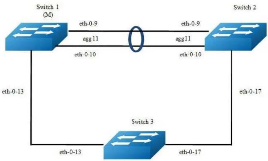
flowchart
graph TD
A["Switch 1 (M)"] -->|eth-0-9| B["Switch 2"]
A -->|agg-11| C["Switch 3"]
B -->|eth-0-9| A
B -->|agg-11| A
C -->|eth-0-13| A
C -->|eth-0-17| B
C -->|eth-0-13| C
C -->|eth-0-17| B
Figure 16-15 ERPS
Configure same ERPS domain and ring at Switch1, Switch2 and Switch3. Switch1 is configured as ERPS master node and other two switches are configured as ERPS transit nodes. Interface agg11, which has two members called eth-0-9 and eth-0-10, is configured as primary interface at Switch1 and eth-0-13 is configured as secondary interface.

NOTE
The ports accessing an ERPS ring must be configured as trunk ports, permitting the traffic of data VLANs to pass through. If the switch is enabled stacking, the port of ERPS ring should not on slave stacking device.
The ports accessing an ERPS ring must be configured as the members of the control VLAN, allowing the ERPS packets to be sent and received.
➢ STP on ports accessing ERPS rings must be disabled.
Only one node can be configured as master node.
Control VLAN must not be configured as Layer 3 interface.
VLAN mapping must not be enabled on the ERPS ports.
Native VLAN of a port accessing an ERPS ring must not be set as the primary control VLAN or the secondary control VLAN.
The following configuration should be operated on all switches if the switch ID is not specified.
step 1 Enter the configure mode
Switch# configure terminal
step 2 Enter the vlan configure mode and create the vlan
Switch(config)# vlan database
Switch(config-vlan)# vlan 15
Switch(config-vlan)# exit
step 3 Enter the interface configure mode and set the attributes of the interface
As the topology shows, eth-0-9 and eth-0-10 of Switch1 and Switch2 join agg 11 and connect to each other directly. eth-0-13 of Switch1 and Switch3 connect to each other directly. eth-0-17 of Switch2 and Switch3 connect to each other directly.
Interface agg 11 configuration for Switch1 and Switch2:
Switch(config)# interface eth-0-9
Switch(config-if)# no shutdown
Switch(config-if)# switchport mode trunk
Switch(config-if)# switchport trunk allowed vlan add 15
Switch(config-if)# static-channel-group 11
Switch(config-if)# exit
Switch(config)# interface eth-0-10
Switch(config-if)# no shutdown
Switch(config-if)# switchport mode trunk
Switch(config-if)# switchport trunk allowed vlan add 15
Switch(config-if)# static-channel-group 11
Switch(config-if)# exit
Switch(config)# interface agg11
Switch(config-if)# spanning-tree port disable
Interface eth-0-13 configuration for Switch1 and Switch3:
Switch(config)# interface eth-0-13
Switch(config-if)# no shutdown
Switch(config-if)# switchport mode trunk
Switch(config-if)# switchport trunk allowed vlan add 15
Switch(config-if)# spanning-tree port disable
Switch(config-if)# exit
Interface eth-0-17 configuration for Switch2 and Switch3:
Switch(config)# interface eth-0-17
Switch(config-if)# no shutdown
Switch(config-if)# switchport mode trunk
Switch(config-if)# switchport trunk allowed vlan add 15
Switch(config-if)# spanning-tree port disable
Switch(config-vlan)# exit
step 4 Create and enable ERPS domain.
ERPS domain for Switch1:
Switch(config)# erps 11
Switch(config)# erps 11 primary control vlan 15
Switch(config)# erps 11 mstp instance 0
Switch(config)# erps 11 ring 1 level primary
Switch(config)# erps 11 ring 1 mode master
Switch(config)# erps 11 ring 1 primary interface agg11
Switch(config)# erps 11 ring 1 secondary interface eth-0-13
Switch(config)# erps 11 ring 1 enable
Switch(config)# erps 11 enable
ERPS domain for Switch2:
Switch(config)# erps 11
Switch(config)# erps 11 primary control vlan 15
Switch(config)# erps 11 mstp instance 0
Switch(config)# erps 11 ring 1 level primary
Switch(config)# erps 11 ring 1 mode transit
Switch(config)# erps 11 ring 1 primary interface aggl1
Switch(config)# erps 11 ring 1 secondary interface eth-0-17
Switch(config)# erps 11 ring 1 enable
Switch(config)# erps 11 enable
ERPS domain for Switch3:
Switch(config)# erps 11
Switch(config)# erps 11 primary control vlan 15
Switch(config)# erps 11 mstp instance 0
Switch(config)# erps 11 ring 1 level primary
Switch(config)# erps 11 ring 1 mode transit
Switch(config)# erps 11 ring 1 primary interface eth-0-17
Switch(config)# erps 11 ring 1 secondary interface eth-0-13
Switch(config)# erps 11 ring 1 enable
Switch(config)# erps 11 enable
step 5 Exit the configure mode
Switch(config)# end
step 6 Validation
Display the result on Switch1.
Switch# show erps 11
ERPS domain ID: 11
ERPS domain name: ERPS0011
ERPS domain mode: normal
ERPS domain primary control VLAN ID: 15
ERPS domain sub control VLAN ID: 0
ERPS domain hello timer interval: 1 second(s)
ERPS domain fail timer interval: 3 second(s)
ERPS domain protected mstp instance: 0
ERPS ring ID: 1
ERPS ring level: primary
ERPS ring 1 node mode: master
ERPS ring 1 node state: complete
ERPS ring 1 primary interface name: agg11 state:unblock
ERPS ring 1 secondary interface name: eth-0-13 state:block
ERPS ring 1 stats:
Sent:
total packets:51
hello packets:47 ring-up-flush-fdb packets:2
ring-down-flush-fdb packets:2 link-down packets:0
edge-hello packets:0 major-fault packets:0
Received:
total packets:21
hello packets:21 ring-up-flush-fdb packets:0
ring-down-flush-fdb packets:0 link-down packets:0
edge-hello packets:0 major-fault packets:0
Display the result on Switch2.
Switch# show erps 11
ERPS domain ID: 11
ERPS domain name: ERPS0011
ERPS domain mode: normal
ERPS domain primary control VLAN ID: 15
ERPS domain sub control VLAN ID: 0
ERPS domain hello timer interval: 1 second(s)
ERPS domain fail timer interval: 3 second(s)
ERPS domain protected mstp instance: 0
ERPS ring ID: 1
ERPS ring level: primary
ERPS ring 1 node mode: transit
ERPS ring 1 node state: link up
ERPS ring 1 primary interface name: aggll state:unblock
ERPS ring 1 secondary interface name: eth-0-17 state:unblock
ERPS ring 1 stats:
Sent:
total packets:0
hello packets:0 ring-up-flush-fdb packets:0
ring-down-flush-fdb packets:0 link-down packets:0
edge-hello packets:0 major-fault packets:0
Received:
total packets:114
hello packets:113 ring-up-flush-fdb packets:1
ring-down-flush-fdb packets:0 link-down packets:0
edge-hello packets:0 major-fault packets:0
Display the result on Switch3.
Switch# show erps 11
ERPS domain ID: 11
ERPS domain name: ERPS0011
ERPS domain mode: normal
ERPS domain primary control VLAN ID: 15
ERPS domain sub control VLAN ID: 0
ERPS domain hello timer interval: 1 second(s)
ERPS domain fail timer interval: 3 second(s)
ERPS domain protected mstp instance: 0
ERPS ring ID: 1
ERPS ring level: primary
ERPS ring 1 node mode: transit
ERPS ring 1 node state: link up
ERPS ring 1 primary interface name: eth-0-17 state:unblock
ERPS ring 1 secondary interface name: eth-0-13 state:unblock
ERPS ring 1 stats:
Sent:
total packets:0
hello packets:0 ring-up-flush-fdb packets:0
ring-down-flush-fdb packets:0 link-down packets:0
edge-hello packets:0 major-fault packets:0
Received:
total packets:130
hello packets:129 ring-up-flush-fdb packets:1
ring-down-flush-fdb packets:0 link-down packets:0
edge-hello packets:0 major-fault packets:0
Configuring a Intersecting-Ring Topology
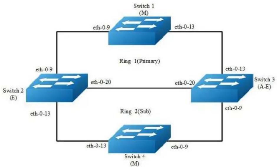
flowchart
graph TD
A["Switch 1 (M)"] -->|eth-0-9| B["Switch 2 (E)"]
B -->|eth-0-13| A
A -->|eth-0-13| C["Switch 4 (M)"]
C -->|eth-0-9| B
B -->|eth-0-20| A
A -->|eth-0-13| D["Switch 3 (A-E)"]
D -->|eth-0-13| A
D -->|eth-0-20| B
B -->|eth-0-9| C
C -->|eth-0-13| B
style A fill:#4CAF50,stroke:#388E3C
style B fill:#4CAF50,stroke:#388E3C
style C fill:#4CAF50,stroke:#388E3C
style D fill:#4CAF50,stroke:#388E3C
Figure 16-16 ERPS
Configure same ERPS domain at Switch1, Switch2, Switch3 and Switch4. Switch1, Switch2 and Switch3 consist of ERPS primary ring 1 while Switch2, Switch3 and Switch4 consist of ERPS sub ring 2. Switch1 is configured as ERPS ring 1 master node and other two switches are configured as ERPS transit nodes while Switch4 is configured as ERPS ring 2 master node. In addition, Switch2 is configured as edge node and Switch3 is configured as assistant-edge node.
The ports accessing an ERPS ring must be configured as trunk ports, permitting the traffic of data VLANs to pass through.
step 1 Enter the configure mode
Switch# configure terminal
step 2 Enter the vlan configure mode and create the vlan
Switch(config)# vlan database
Switch(config-vlan)# vlan 11,12
Switch(config-vlan)# exit
step 3 Enter the interface configure mode and set the attributes of the interface
Switch(config)# interface eth-0-9
Switch(config-if)# no shutdown
Switch(config-if)# switchport mode trunk
Switch(config-if)# switchport trunk allowed vlan add 11,12
Switch(config-if)# spanning-tree port disable
Switch(config-if)# exit
Switch(config)# interface eth-0-13
Switch(config-if)# no shutdown
Switch(config-if)# switchport mode trunk
Switch(config-if)# switchport trunk allowed vlan add 11,12
Switch(config-if)# spanning-tree port disable
Switch(config-if)# exit
Interface eth-0-20 configuration for Switch2 and Switch3:
Switch(config)# interface eth-0-20
Switch(config-if)# no shutdown
Switch(config-if)# switchport mode trunk
Switch(config-if)# switchport trunk allowed vlan add 11,12
Switch(config-if)# spanning-tree port disable
Switch(config-if)# exit
step 4 Create and enable ERPS domain.
ERPS domain for Switch1:
Switch(config)# erps 1
Switch(config)# erps 1 primary control vlan 11
Switch(config)# erps 1 sub control vlan 12
Switch(config)# erps 1 mstp instance 0
Switch(config)# erps 1 ring 1 level primary
Switch(config)# erps 1 ring 1 mode master
Switch(config)# erps 1 ring 1 primary interface eth-0-9
Switch(config)# erps 1 ring 1 secondary interface eth-0-13
Switch(config)# erps 1 ring 1 enable
Switch(config)# erps 1 enable
ERPS domain for Switch2:
Switch(config)# erps 1
Switch(config)# erps 1 primary control vlan 11
Switch(config)# erps 1 sub control vlan 12
Switch(config)# erps 1 mstp instance 0
Switch(config)# erps 1 ring 1 level primary
Switch(config)# erps 1 ring 1 mode transit
Switch(config)# erps 1 ring 1 primary interface eth-0-9
Switch(config)# erps 1 ring 1 secondary interface eth-0-20
Switch(config)# erps 1 ring 1 enable
Switch(config)# erps 1 ring 2 level sub
Switch(config)# erps 1 ring 2 edge-mode edge
Switch(config)# erps 1 ring 2 edge interface eth-0-13
Switch(config)# erps 1 ring 2 common interface eth-0-20
Switch(config)# erps 1 ring 2 srpt disable
Switch(config)# erps 1 ring 2 enable
Switch(config)# erps 1 enable
ERPS domain for Switch3:
Switch(config)# erps 1
Switch(config)# erps 1 primary control vlan 11
Switch(config)# erps 1 sub control vlan 12
Switch(config)# erps 1 mstp instance 0
Switch(config)# erps 1 ring 1 level primary
Switch(config)# erps 1 ring 1 mode transit
Switch(config)# erps 1 ring 1 primary interface eth-0-13
Switch(config)# erps 1 ring 1 secondary interface eth-0-20
Switch(config)# erps 1 ring 1 enable
Switch(config)# erps 1 ring 2 level sub
Switch(config)# erps 1 ring 2 edge-mode assistant-edge
Switch(config)# erps 1 ring 2 edge interface eth-0-9
Switch(config)# erps 1 ring 2 common interface eth-0-20
Switch(config)# erps 1 ring 2 enable
Switch(config)# erps 1 enable
ERPS domain for Switch4:
Switch(config)# erps 1
Switch(config)# erps 1 sub control vlan 12
Switch(config)# erps 1 mstp instance 0
Switch(config)# erps 1 ring 2 level sub
Switch(config)# erps 1 ring 2 mode master
Switch(config)# erps 1 ring 2 primary interface eth-0-9
Switch(config)# erps 1 ring 2 secondary interface eth-0-13
Switch(config)# erps 1 ring 2 enable
Switch(config)# erps 1 enable
step 5 Exit the configure mode
Switch(config)# end
step 6 Validation
Display the result on Switch1.
Switch# show erps 1
ERPS domain ID: 1
ERPS domain name: ERPS001
ERPS domain mode: normal
ERPS domain primary control VLAN ID: 11
ERPS domain sub control VLAN ID: 12
ERPS domain hello timer interval: 1 second(s)
ERPS domain fail timer interval: 3 second(s)
ERPS domain protected mstp instance: 0
ERPS ring ID: 1
ERPS ring level: primary
ERPS ring 1 node mode: master
ERPS ring 1 node state: complete
ERPS ring 1 primary interface name: eth-0-9 state:unblock
ERPS ring 1 secondary interface name: eth-0-13 state:block
ERPS ring 1 stats:
Sent:
total packets:1310
hello packets:1303 ring-up-flush-fdb packets:3
ring-down-flush-fdb packets:4 link-down packets:0
edge-hello packets:0 major-fault packets:0
Received:
total packets:921
hello packets:921 ring-up-flush-fdb packets:0
ring-down-flush-fdb packets:0 link-down packets:0
edge-hello packets:0 major-fault packets:0
Display the result on Switch2.
Switch# show erps 1
ERPS domain ID: 1
ERPS domain name: ERPS001
ERPS domain mode: normal
ERPS domain primary control VLAN ID: 11
ERPS domain sub control VLAN ID: 12
ERPS domain hello timer interval: 1 second(s)
ERPS domain fail timer interval: 3 second(s)
ERPS domain protected mstp instance: 0
ERPS ring ID: 1
ERPS ring level: primary
ERPS ring 1 node mode: transit
ERPS ring 1 node state: link up
ERPS ring 1 primary interface name: eth-0-9 state:unblock
ERPS ring 1 secondary interface name: eth-0-20 state:unblock
ERPS ring 1 stats:
Sent:
total packets:0
hello packets:0 ring-up-flush-fdb packets:0
ring-down-flush-fdb packets:0 link-down packets:0
edge-hello packets:0 major-fault packets:0
Received:
total packets:988
hello packets:985 ring-up-flush-fdb packets:2
ring-down-flush-fdb packets:1 link-down packets:0
edge-hello packets:0 major-fault packets:0
ERPS ring ID: 2
ERPS ring level: sub
ERPS ring 2 node mode: transit
ERPS ring 2 edge node mode: edge
ERPS ring 2 node state: link up
ERPS ring 2 edge interface name: eth-0-13 state: ur
ERPS ring 2 common interface name: eth-0-20 state: unblock
EPRS ring 2 SRPT is disabled
ERPS ring 2 stats:
Sent:
total packets:0
hello packets:0 ring-up-flush-fdb packets:0
ring-down-flush-fdb packets:0 link-down packets:0
edge-hello packets:0 major-fault packets:0
Received:
total packets:858
hello packets:856 ring-up-flush-fdb packets:1
ring-down-flush-fdb packets:1 link-down packets:0
edge-hello packets:0 major-fault packets:0
Display the result on Switch3.
Switch# show erps 1
ERPS domain ID: 1
ERPS domain name: ERPS001
ERPS domain mode: normal
ERPS domain primary control VLAN ID: 11
ERPS domain sub control VLAN ID: 12
ERPS domain hello timer interval: 1 second(s)
ERPS domain fail timer interval: 3 second(s)
ERPS domain protected mstp instance: 0
ERPS ring ID: 1
ERPS ring level: primary
ERPS ring 1 node mode: transit
ERPS ring 1 node state: link up
ERPS ring 1 primary interface name: eth-0-13 state:unblock
ERPS ring 1 secondary interface name: eth-0-20 state:unblock
ERPS ring 1 stats:
Sent:
total packets:0
hello packets:0 ring-up-flush-fdb packets:0
ring-down-flush-fdb packets:0 link-down packets:0
edge-hello packets:0 major-fault packets:0
Received:
total packets:645
hello packets:644 ring-up-flush-fdb packets:1
ring-down-flush-fdb packets:0 link-down packets:0
edge-hello packets:0 major-fault packets:0
ERPS ring ID: 2
ERPS ring level: sub
ERPS ring 2 node mode: transit
ERPS ring 2 edge node mode: assistant edge
ERPS ring 2 node state: link up
ERPS ring 2 edge interface name: eth-0-9 state: unblock
ERPS ring 2 common interface name: eth-0-20 state: unblock
ERPS ring 2 stats:
Sent:
total packets:0
hello packets:0 ring-up-flush-fdb packets:0
ring-down-flush-fdb packets:0 link-down packets:0
edge-hello packets:0 major-fault packets:0
Received:
total packets:645
hello packets:644 ring-up-flush-fdb packets:1
ring-down-flush-fdb packets:0 link-down packet:0
edge-hello packets:0 major-fault packet:0
Display the result on Switch4.
Switch# show erps 1
ERPS domain ID: 1
ERPS domain name: ERPS001
ERPS domain mode: normal
ERPS domain primary control VLAN ID: 0
ERPS domain sub control VLAN ID: 12
ERPS domain hello timer interval: 1 second(s)
ERPS domain fail timer interval: 3 second(s)
ERPS domain protected mstp instance: 0
ERPS ring ID: 2
ERPS ring level: sub
ERPS ring 2 node mode: master
ERPS ring 2 node state: complete
ERPS ring 2 primary interface name: eth-0-9 state:unblock
ERPS ring 2 secondary interface name: eth-0-13 state:block
ERPS ring 2 stats:
Sent:
total packets:814
hello packets:810 ring-up-flush-fdb packets:2
ring-down-flush-fdb packets:2 link-down packets:0
edge-hello packets:0 major-fault packets:0
Received:
total packets:774
hello packets:774 ring-up-flush-fdb packets:0
ring-down-flush-fdb packets:0 link-down packets:0
edge-hello packets:0 major-fault packets:0
Switch#
16.8.3 Application cases
N/A
16.9 Configuring Smart Link
16.9.1 Overview
Function Introduction
The Smart Link is a simple but practical technology of fast link protection. It is a solution specific to dual uplink networking to fulfill redundancy and fast migration of active and standby links.
Every smart-link group is included a pair of a layer 2 interfaces where one interface is configured to act as a standby to the other. The feature provides an alternative solution to the STP. Users can disable STP and still retain basic link redundancy. The feature also supports load-balancing so than both interfaces simultaneously forward the traffic.
Principle Description
N/A
16.9.2 Configuration
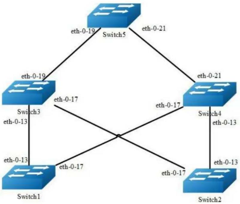
flowchart
graph TD
Switch1["Switch1"] -->|eth-0-13| Switch3["Switch3"]
Switch1 -->|eth-0-17| Switch5["Switch5"]
Switch2["Switch2"] -->|eth-0-13| Switch4["Switch4"]
Switch3 -->|eth-0-19| Switch5
Switch4 -->|eth-0-21| Switch5
Switch1 -->|eth-0-17| Switch4
Switch3 -->|eth-0-17| Switch4
Figure 16-17 Smart-Link Typical Topology
The figure above is a typical smart-link application. The Switch1 and Switch2 are configured smart-link group. Switch3, Switch4 and Switch5 are configured smart-link flush receiver.
To configure smart-link group, some configuration should be configured before it.
VLANs should be configured.
MSTP instance should be configured.
Spanning-tree should be disabled in the interface.
About above configurations, please see the related references.
The following configuration should be operated on all switches if the switch ID is not specified.
step 1 Enter the configure mode
Switch# configure terminal
step 2 Enter the vlan configure mode and create the vlan
Switch(config)# vlan database
Switch(config-vlan)# vlan 2-20
Switch(config-vlan)# exit
step 3 Set the spanning tree mode and create mstp instance
Create the mstp instance on Switch1 and Switch2:
Switch(config)# spanning-tree mode mstp
Switch(config)# spanning-tree mst configuration
Switch(config-mst)# instance 1 vlan 1
Switch(config-mst)# instance 2 vlan 2
Switch(config-mst)# instance 3 vlan 3
Switch(config-mst)# instance 10 vlan 10
Switch(config-mst)# exit
step 4 Enter the interface configure mode and set the attributes of the interface
Interface configuration for Switch1 and Switch2:
Switch(config)# interface eth-0-13
Switch(config-if)# switchport mode trunk
Switch(config-if)# switchport trunk allowed vlan all
Switch(config-if)# spanning-tree port disable
Switch(config-if)# no shutdown
Switch(config-if)# exit
Switch(config)# interface eth-0-17
Switch(config-if)# switchport mode trunk
Switch(config-if)# switchport trunk allowed vlan all
Switch(config-if)# spanning-tree port disable
Switch(config-if)# no shutdown
Switch(config-if)# exit
Interface configuration for Switch3 and Switch4:
Switch(config)# interface eth-0-13
Switch(config-if)# switchport mode trunk
Switch(config-if)# no shutdown
Switch(config-if)# switchport trunk allowed vlan all
Switch(config-if)# smart-link flush receive control-vlan 10 password simple test
Switch(config-if)# exit
Switch(config)# interface eth-0-17
Switch(config-if)# no shutdown
Switch(config-if)# switchport mode trunk
Switch(config-if)# switchport trunk allowed vlan all
Switch(config-if)# smart-link flush receive control-vlan 10 password simple test
Switch (config-if)# exit
Interface eth-0-19 configuration for Switch3:
Switch(config)# interface eth-0-19
Switch(config-if)# switchport mode trunk
Switch(config-if)# no shutdown
Switch(config-if)# switchport trunk allowed vlan all
Switch(config-if)# exit
Interface eth-0-21 configuration for Switch4:
Switch(config)# interface eth-0-21
Switch(config-if)# switchport mode trunk
Switch(config-if)# no shutdown
Switch(config-if)# switchport trunk allowed vlan all
Switch(config-if)# exit
Interface configuration for Switch5:
Switch(config)# interface eth-0-19
Switch(config-if)# switchport mode trunk
Switch(config-if)# no shutdown
Switch(config-if)# switchport trunk allowed vlan all
Switch(config-if)# smart-link flush receive control-vlan 10 password simple test
Switch(config-if)# exit
Switch(config)# interface eth-0-21
Switch(config-if)# switchport mode trunk
Switch(config-if)# no shutdown
Switch(config-if)# switchport trunk allowed vlan all
Switch(config-if)# smart-ink flush receive control-vlan 10 password simple test
Switch(config-if)# exit
step 5 Create smart link group and set the attributes of the group
Create smart link group on Switch1 and Switch2:
Switch(config)# smart-link group 1
Switch(config-smlk-group)# interface eth-0-13 master
Switch(config-smlk-group)# interface eth-0-17 slave
Switch(config-smlk-group)# protected mstp instance 1
Switch(config-smlk-group)# protected mstp instance 2
Switch(config-smlk-group)# protected mstp instance 3
Switch(config-smlk-group)# protected mstp instance 10
Switch(config-smlk-group)# load-balance instance 3
Switch(config-smlk-group)# restore time 40
Switch(config-smlk-group)# restore enable
Switch(config-smlk-group)# flush send control-vlan 10 password simple test
Switch(config-smlk-group)# group enable
Switch(config-smlk-group)# exit
step 6 Disable the smart link relay function
Configure on Switch5:
Switch(config)# no smart-link relay enable
step 7 Exit the configure mode
Switch(config)# end
step 8 Validation
Display the result on Switch1.
Switch1# show smart-link group 1
Smart-link group 1 information:
The smart-link group was enabled.
Auto-restore:
state time count Last-time
enabled 40 0 N/A
Protected instance: 1 2 3
Load balance instance: 3
Flush sender, Control-vlan ID: 10 Password:test
INTERFACE:
Role Member DownCount Last-Down-Time FlushCount Last-Flush-Time
MASTER eth-0-13 0 N/A 0 N/A
SLAVE eth-0-17 0 N/A 0 N/A
Instance states in the member interfaces:
A - ACTIVE, B -BLOCK, D-The interface is link-down
Map-instance-ID MASTER(eth-0-13) SLAVE(eth-0-17)
1 A B
2 A B
3 B A
Display the result on Switch2.
Switch# show smart-link group 1
Smart-link group 1 information:
The smart-link group was enabled.
====================
Auto-restore:
state time count Last-time
enabled 40 0 N/A
------------
Protected instance: 1 2 3
Load balance instance: 3
Flush sender, Control-vlan ID: 10 Password:test
------------
INTERFACE:
Role Member DownCount Last-Down-Time FlushCount Last-Flush-Time
MASTER eth-0-13 0 N/A 0 N/A
SLAVE eth-0-17 0 N/A 0 N/A
------------
Instance states in the member interfaces:
A - ACTIVE, B - BLOCK, D-The interface is link-down
Map-instance-ID MASTER(eth-0-13) SLAVE(eth-0-17)
1 A B
2 A B
3 B A
Display the result on Switch3.
Switch# show smart-link
Relay smart-link flush packet is enabled
Smart-link flush receiver interface:
eth-0-13 control-vlan:10 password:test
eth-0-17 control-vlan:10 password:test
Smart-link received flush packet number:0
Smart-link processed flush packet number:0
Smart link Group Number is 0.
Display the result on Switch4.
Switch# show smart-link
Relay smart-link flush packet is enabled
Smart-link flush receiver interface:
eth-0-13 control-vlan:10 password:test
eth-0-17 control-vlan:10 password:test
Smart-link received flush packet number:0
Smart-link processed flush packet number:0
Smart link Group Number is 0.
Display the result on Switch5.
Switch# show smart-link
Relay smart-link flush packet is disabled
Smart-link flush receiver interface:
eth-0-21 control-vlan:10 password: test
eth-0-19 control-vlan:10 password:test
Smart-link received flush packet number:0
Smart-link processed flush packet number:0
Smart link Group Number is 0.
16.9.3 Application cases
N/A
16.10 Configuring Multi-Link
16.10.1 Overview
Function Introduction
The Multi-Link is a simple but practical technology of fast link protection. It is a solution specific to multi-uplink networking to fulfill redundancy and fast migration of between links.
The feature is like smart link, but links extend to four instead of two.
Principle Description
N/A
16.10.2 Configuration
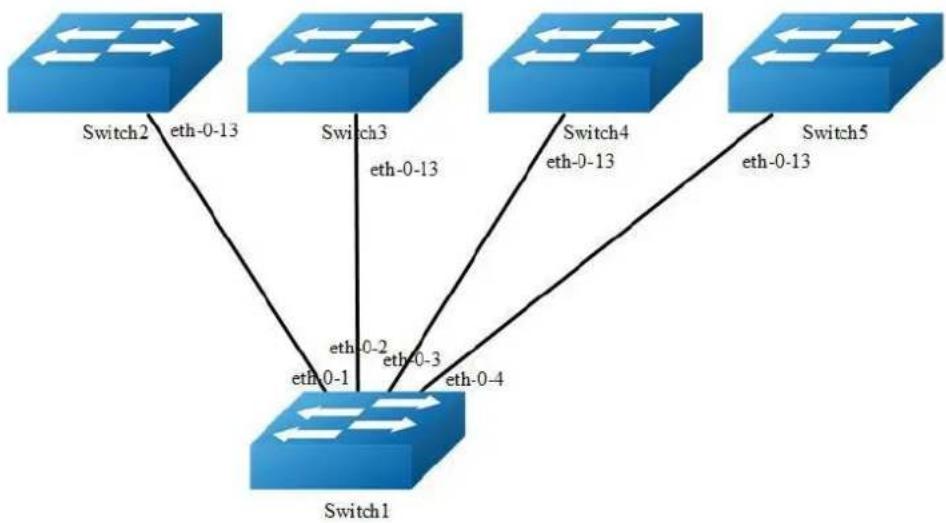
flowchart
graph TD
Switch1["Switch1"] -->|eth-0-1| Switch2["Switch2"]
Switch1 -->|eth-0-2| Switch3["Switch3"]
Switch1 -->|eth-0-3| Switch4["Switch4"]
Switch1 -->|eth-0-4| Switch5["Switch5"]
Switch2 -->|eth-0-13| Switch3
Switch3 -->|eth-0-13| Switch4
Switch4 -->|eth-0-13| Switch5
Figure 16-18 Multi-Link Typical Topology
The figure above is a typical multi-link application. The Switch1 are configured multi-link group. Switch2, Switch3, Switch4 and Switch5 are configured multi-link flush receiver.
To configure Multi-link group, some configuration should be configured before it.
VLANs should be configured.
MSTP instance should be configured.
➢ Spanning-tree should be disabled in the interface.
About above configurations, please see the related references.
The following configuration should be operated on all switches if the switch ID is not specified.
step 1 Enter the configure mode
Switch# configure terminal
step 2 Enter the vlan configure mode and create the vlan
Switch(config)# vlan database
Switch(config-vlan)# vlan 2-10
Switch(config-vlan)# exit
step 3 Set the spanning tree mode and create mstp instance
Switch(config)# spanning-tree mode mstp
Switch(config)# spanning-tree mst configuration
Switch(config-mst)# instance 1 vlan 1
Switch(config-mst)# instance 2 vlan 2
Switch(config-mst)# instance 3 vlan 3
Switch(config-mst)# instance 4 vlan 4-10
Switch(config-mst)# exit
step 4 Enter the interface configure mode and set the attributes of the interface
Interface configuration for Switch1:
Switch(config)# interface range eth-0-1 - 4
Switch(config-if)# switchport mode trunk
Switch(config-if)# switchport trunk allowed vlan all
Switch(config-if)# spanning-tree port disable
Switch(config-if)# no shutdown
Switch(config-if)# exit
Interface configuration for Switch1 \~ 5:
Switch(config)# interface eth-0-13
Switch(config-if)# switchport mode trunk
Switch(config-if)# switchport trunk allowed vlan all
Switch(config-if)# multi-link flush receive control-vlan 10 password simple test
Switch(config-if)# no shutdown
Switch(config-if)# exit
step 5 Create multi link group and set the attributes of the group
Create multi link group on Switch1:
Switch(config)# multi-link group 1
Switch(config-multilk-group)# interface eth-0-1 priority 1
Switch(config-multilk-group)# interface eth-0-2 priority 2
Switch(config-multilk-group)# interface eth-0-3 priority 3
Switch(config-multilk-group)# interface eth-0-4 priority 4
Switch(config-multilk-group)# protected mstp instance 1
Switch(config-multilk-group)# protected mstp instance 2
Switch(config-multilk-group)# protected mstp instance 3
Switch(config-multilk-group)# protected mstp instance 4
Switch(config-multilk-group)# load-balance instance 2 priority 2
Switch(config-multilk-group)# load-balance instance 3 priority 3
Switch(config-multilk-group)# load-balance instance 4 priority 4
Switch(config-multilk-group)# restore time 40
Switch(config-multilk-group)# restore enable
Switch(config-multilk-group)# flush send control-vlan 10 password simple test
Switch(config-multilk-group)# group enable
Switch(config-multilk-group)# exit
step 6 Exit the configure mode
Switch(config)# end
step 7 Validation
Display the result on Switch1.
Switch# show multi-link group 1
Multi-link group 1 information:
The multi-link group was enabled.
Auto-restore:
state time count Last-time
enabled 40 0 N/A
Protected instance: 1 2 3 4
Load balance instance: 2(to P2) 3(to P3) 4(to P4)
Flush sender, Control-vlan ID: 10 Password:test
INTERFACE:
Role Member DownCount Last-Down-Time FlushCount Last-Flush-Time
PRI1 eth-0-1 0 N/A 1 2016/09/05,07:13:24
PRI2 eth-0-2 0 N/A 1 2016/09/05,07:13:24
PRI3 eth-0-3 0 N/A 1 2016/09/05,07:13:24
PRI4 eth-0-4 0 N/A 1 2016/09/05,07:13:24
Instance states in the member interfaces:
A - ACTIVE, B - BLOCK, D-The interface is link-down
Map-instance-ID P1(eth-0-1) P2(eth-0-2) P3(eth-0-3) P4(eth-0-4)
Switch# show multi-link
Relay multi-link flush packet is enabled
Multi-link flush receiver interface:
eth-0-13 control-vlan:10 password:test
Multi-link received flush packet number:0
Multi-link processed flush packet number:0
Multi-link tcn is disabled
Multi-link tcn query count 2
Multi-link tcn query interval 10
Multi-link Group Number is 0.
16.10.3 Application cases
Configuring Multi-Link Enhance
There is an enhanced method to improve the ability of multi-link to protect link. When all the interfaces of multi-link group are down, you can enable another interface to send the enhance packet to peer which makes the instance state of one interface to change from block to active. It would avoid the switch being the state of islet.
When 2 multi-link group on different switches backup for each other, multi-link members on one switch is blocked and can not protect the traffic.
In this example:
Core switch A and B, Access switch A and B, make up a full-match topology.
Enable multi-link on Access switch A, the priority for link a/b/c is 1/2/3.
Enable multi-link on Access switch B, the priority for link d/e is 1/2.
In normal condition, link b/c/e are block, link a/d are active. As the following figure shows:
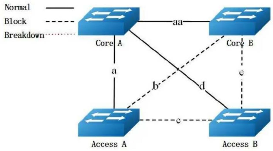
flowchart
graph TD
A["Access A"] -->|a| B["Core A"]
A -->|b| C["Access B"]
B -->|c| C
C -->|d| B
B -->|aa| C
C -->|e| B
style A fill:#4CAF50,stroke:#388E3C
style B fill:#2196F3,stroke:#388E3C
style C fill:#2196F3,stroke:#388E3C
linkStyle 0 stroke:#000,stroke-width:2px
linkStyle 1 stroke:#000,stroke-width:2px
linkStyle 2 stroke:#000,stroke-width:2px
linkStyle 3 stroke:#000,stroke-width:2px
linkStyle 4 stroke:#000,stroke-width:2px
linkStyle 5 stroke:#000,stroke-width:2px
linkStyle 6 stroke:#000,stroke-width:2px
linkStyle 7 stroke:#000,stroke-width:2px
linkStyle 8 stroke:#000,stroke-width:2px
linkStyle 9 stroke:#000,stroke-width:2px
linkStyle 10 stroke:#000,stroke-width:2px
note1["Normal"] --> A
note2["Block"] --> A
note3["Breakdown"] --> A
When link d/e are break down, the only out going link for Access switch B is link c, which is between Access switch A and Access switch B.
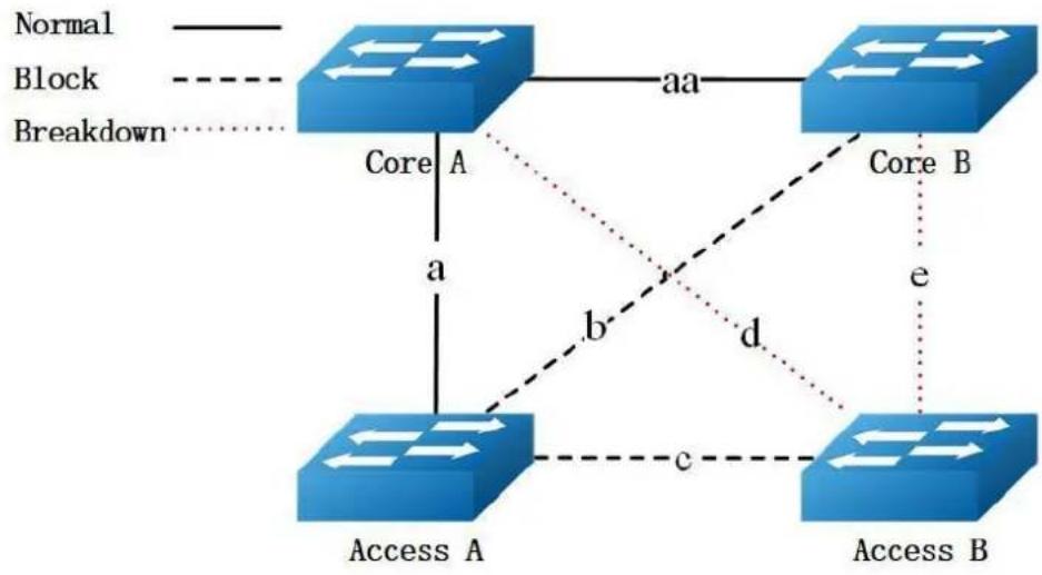
flowchart
graph TD
A["Access A"] -->|a| B["Core A"]
A -->|b| C["Access B"]
A -->|c| C
B -->|aa| D["Core B"]
C -->|e| D
style A fill:#4CAF50,stroke:#388E3C
style B fill:#4CAF50,stroke:#388E3C
style C fill:#4CAF50,stroke:#388E3C
style D fill:#4CAF50,stroke:#388E3C
note1["Normal"]
note2["Block"]
note3["Breakdown"]
Because link c is blocked, the Access switch B is the state of islet. As the following figure shows:
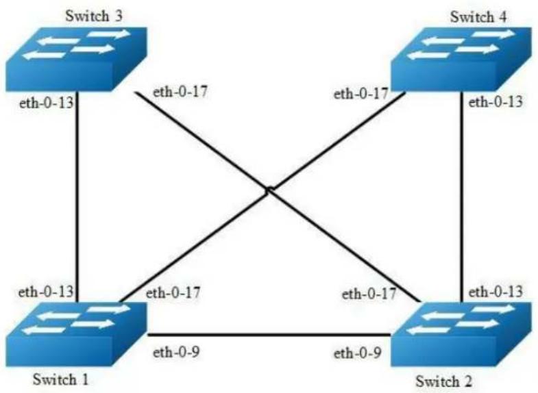
flowchart
graph TD
Switch1["Switch 1"] -->|eth-0-13| Switch3["Switch 3"]
Switch1 -->|eth-0-9| Switch2["Switch 2"]
Switch1 -->|eth-0-17| Switch4["Switch 4"]
Switch2 -->|eth-0-17| Switch3
Switch2 -->|eth-0-9| Switch1
Switch3 -->|eth-0-17| Switch4
Switch3 -->|eth-0-13| Switch1
Figure 16-19 Multilink-enhance Typical Topology
The figure above is a typical multi-link application. The Switch1, 2 are configured multi-link group. Switch1 has the interface which receives the multilink-enhance packets. And, Switch2 has the interface which sends the multilink-enhance packets.
To configure multi-link group, some configuration should be configured before it.
VLANs should be configured.
MSTP instance should be configured.
Spanning-tree should be disabled in the interface.
About above configurations, please see the related references.
It should configure the control vlan and password of flush sending before setting the multilink-enhance interface.
The following configuration should be operated on all switches if the switch ID is not specified.
step 1 Enter the configure mode
Switch# configure terminal
step 2 Enter the vlan configure mode and create the vlan
Switch(config)# vlan database
Switch(config-vlan)# vlan 10
Switch(config-vlan)# vlan 20
Switch(config-vlan)# vlan 30
Switch(config-vlan)# vlan 40
Switch(config-vlan)# exit
step 3 Set the spanning tree mode and create mstp instance
Switch(config)# spanning-tree mode mstp
Switch(config)# spanning-tree mst configuration
Switch(config-mst)# instance 1 vlan 10
Switch(config-mst)# instance 1 vlan 30
Switch(config-mst)# instance 2 vlan 20
Switch(config-mst)# instance 2 vlan 40
Switch(config-mst)# exit
step 4 Enter the interface configure mode and set the attributes of the interface
Interface configuration for Switch1:
Switch1(config)# interface range eth-0-9
Switch1(config-if)# switchport mode trunk
Switch1(config-if)# switchport trunk allowed vlan all
Switch1(config-if)# spanning-tree port disable
Switch1(config-if)# no shutdown
Switch1(config-if)# exit
Switch1(config)# interface range eth-0-13
Switch1(config-if)# switchport mode trunk
Switch1(config-if)# switchport trunk allowed vlan all
Switch1(config-if)# spanning-tree port disable
Switch1(config-if)# no shutdown
Switch1(config-if)# exit
Switch1(config)# interface range eth-0-17
Switch1(config-if)# switchport mode trunk
Switch1(config-if)# switchport trunk allowed vlan all
Switch1(config-if)# spanning-tree port disable
Switch1(config-if)# no shutdown
Switch1(config-if)# exit
Interface configuration for Switch2:
Switch(config)# interface eth-0-13
Switch(config-if)# switchport mode trunk
Switch(config-if)# switchport trunk allowed vlan all
Switch(config-if)# no shutdown
Switch(config-if)# exit
Switch(config)# interface eth-0-17
Switch(config-if)# switchport mode trunk
Switch(config-if)# switchport trunk allowed vlan all
Switch(config-if)# no shutdown
Switch(config-if)# exit
Switch(config)# interface eth-0-9
Switch(config-if)# multi-link flush receive control-vlan 30 password simple a
Switch(config-if)#exit
Interface configuration for Switch3:
Switch(config)# interface eth-0-13
Switch(config-if)# multi-link flush receive control-vlan 30 password simple a
Switch(config-if)#exit
Switch(config)# interface eth-0-17
Switch(config-if)# multi-link flush receive control-vlan 30 password simple b
Switch(config-if)#exit
Interface configuration for Switch4:
Switch(config)# interface eth-0-13
Switch(config-if)# multi-link flush receive control-vlan 30 password simple b
Switch(config-if)# exit
Switch(config)# interface eth-0-17
Switch(config-if)# multi-link flush receive control-vlan 30 password simple a
Switch(config-if)# exit
step 5 Create multi link group and set the attributes of the group
Create multi link group on Switch1:
Switch(config)# multi-link group 1
Switch(config-multilk-group)# interface eth-0-13 priority 1
Switch(config-multilk-group)# interface eth-0-17 priority 2
Switch(config-multilk-group)# interface eth-0-9 priority 3
Switch(config-multilk-group)# protected mstp instance 1
Switch(config-multilk-group)# protected mstp instance 2
Switch(config-multilk-group)# flush send control-vlan 30 password simple a
Switch(config-multilk-group)# multilink-enhance receive control-vlan 10 password b
interface eth-0-9
Switch(config-multilk-group)# group enable
Switch(config-multilk-group)# end
Create multi link group on Switch2:
Switch(config)# multi-link group 1
Switch(config-multilk-group)# interface eth-0-13 priority 1
Switch(config-multilk-group)# interface eth-0-17 priority 2
Switch(config-multilk-group)# protected mstp instance 1
Switch(config-multilk-group)# protected mstp instance 2
Switch(config-multilk-group)# flush send control-vlan 10 password simple b
Switch(config-multilk-group)# multilink-enhance interface eth-0-9
Switch(config-multilk-group)# group enable
Switch(config-multilk-group)# exit
step 6 Exit the configure mode
Switch(config)# end
step 7 Validation
Display the result on Switch1.
Switch1# show multi-link group 1
Multi-link group 1 information:
The multi-link group was enabled.
Auto-restore:
| state | time | count | Last-time |
| disabled | 60 | 0 | N/A |
Protected instance: 1 2
Load balance instance:
Flush sender, Control-vlan ID: 30 Password: a
INTERFACE:
| Role | Member | DownCount | Last-Down-Time | FlushCount | Last-Flush-Time |
| PRI1 | eth-0-13 | 0 | N/A | 5 | 2017/05/15,07:50:11 |
| PRI2 | eth-0-17 | 0 | N/A | 0 | N/A |
| PRI3 | eth-0-9 | 1 | 2017/05/15,07:48:46 | 5 | 2017/05/15,07:50:11 |
| PRI4 | N/A | 0 | N/A | 0 | N/A |
Instance states in the member interfaces:
A-ACTIVE, B-BLOCK, A(E)-ENHANCE_ACTIVE D-The interface is link-down
up-instance-ID P1(eth-0-13) P2(eth-0-17) P3(eth-0-9) P4(N/A)
1 A B B D
2 A B B D
Switch# show multi-link
Relay multi-link flush packet is enabled
Multi-link enhance receiver interface:
eth-0-9 control-vlan:10 password:b
Multi-link received flush packet number : 0
Multi-link processed flush packet number: 0
Multi-link received enhance packet number : 4
Multi-link processed enhance packet number: 4
Multi-link tcn is disabled
Multi-link tcn query count : 2
Multi-link tcn query interval : 10
Multi-link Group Number is 1.
Group-ID State Pri-1 Pri-2 Pri-3 Pri-4
1 enabled eth-0-13 eth-0-17 eth-0-9 N/A
Display the result on Switch2.
Switch# show multi-link group1
Multi-link group 1 information:
The multi-link group was enabled.
Auto-restore:
state time count Last-time
disabled 60 0 N/A
Protected instance: 1 2
Load balance instance:
Flush sender, Control-vlan ID: 10 Password: b
Multilk enhance interface: eth-0-9, Control-vlan ID: 10 Password: b
INTERFACE:
Role Member DownCount Last-Down-Time FlushCount Last-Flush-Time
PRI1 eth-0-13 1 2017/05/15,07:49:15 0 N/A
PRI2 eth-0-17 2 2017/05/15,07:50:03 3 2017/05/15,07:50:11
PRI3 N/A 0 N/A 0 N/A
PRI4 N/A 0 N/A 0 N/A
ENHANCE INTERFACE:
Role Member DownCount Last-Down-Time EnhanceCount Last-SendEnhance-Time
M-En eth-0-9 0 N/A 0 N/A
Instance states in the member interfaces:
A-ACTIVE, B-BLOCK, A(E)-ENHANCE_ACTIVE D-The interface is link-down
Map-instance-ID P1(eth-0-13) P2(eth-0-17) P3(N/A) P4(N/A)
1 A B D D
2 A B D D
Switch# show multi-link
Relay multi-link flush packet is enabled
Multi-link received flush packet number: 0
Multi-link processed flush packet number: 0
Multi-link received enhance packet number: 0
Multi-link processed enhance packet number: 0
Multi-link tcn is disabled
Multi-link tcn query count : 2
Multi-link tcn query interval: 10
Multi-link Group Number is 1.
Group-ID State Pri-1 Pri-2 Pri-3 Pri-4
1 enabled eth-0-13 eth-0-17 N/A N/A
16.11 Configuring Monitor Link
16.11.1 Overview
Function Introduction
Monitor Link is a port collaboration function. Monitor Link usually works together with Layer 2 topology protocols. The idea is to monitor the states of uplink ports
and adapt the up/down state of downlink ports to the up/down state of uplink ports, triggering link switchover on the downstream switch in time.
Principle Description
N/A
16.11.2 Configuration
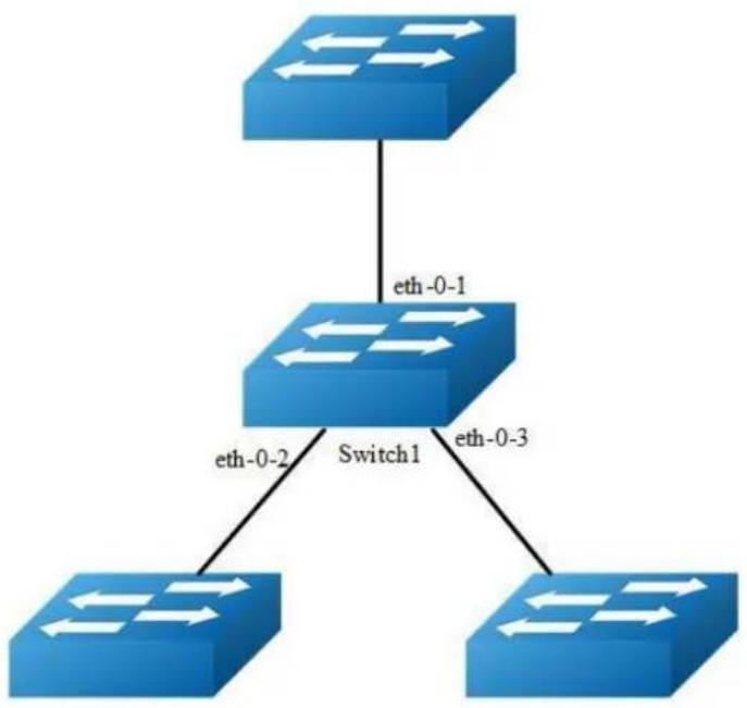
flowchart
graph TD
A["Switch 1"] -->|eth-0-1| B["Switch 2"]
A -->|eth-0-2| C["Switch 3"]
A -->|eth-0-3| D["Switch 4"]
Figure 16-20 monitor link
step 1 Enter the configure mode
Switch# configure terminal
step 2 Enter the interface configure mode and turn on the interface
Switch(config)# interface range eth-0-1 - 3
Switch(config-if-range)# no shutdown
Switch(config-if-range)# exit
step 3 Create multi link group and set the attributes of the group
Switch(config)# monitor-link group 1
Switch(config-mtlk-group)# monitor-link uplink interface eth-0-1
Switch(config-mtlk-group)# monitor-link downlink interface eth-0-2
Switch(config-mtlk-group)# monitor-link downlink interface eth-0-3
Switch(config-mtlk-group)# exit
step 4 Exit the configure mode
Switch(config)# end
step 5 Validation
Switch# show monitor-link group
Group Id: 1
Monitor link status: UP
Role Member Last-up-time Last-down-time upcount downcount
UpLk 1 eth-0-1 2011/07/15,02:07:31 2011/07/15,02:07:31 2 1
DwLk 1 eth-0-2 2011/07/15,02:07:34 2011/07/15,02:07:31 1 1
DwLk 2 eth-0-3 N/A N/A 0 0
16.11.3 Application cases
N/A
16.12 Configuring VRRP
16.12.1 Overview
Function Introduction
This chapter provides an overview of Virtual Router Redundancy Protocol (VRRP) and its implementation. VRRP eliminates the risk of a single point of failure inherent in a static default routing environment. It specifies an election protocol that dynamically assigns responsibility for a virtual router to one of the VRRP routers on a LAN. One of the major advantages of VRRP is that it makes default path available without requiring configuration of dynamic routing on every end-host.

NOTE
MD5 authentication is not yet supported for VRRP.
Principle Description
The VRRP module is based on: RFC 3768 (VRRP): Knight, S., et.al "Virtual Router Redundancy Protocol (VRRP)"
Terminology
Backup Router: VRRP router that back up an IP address. It assumes forwarding responsibility for the virtual IP address if the Master fails.
Critical IP: The IP address that the VRRP router send/receive messages on for a particular session.
IP Address Owner: The VRRP Router that has the virtual router's IP address (es) as real interface address (es). This is the router that, when up, will respond to packets addressed to one of these IP addresses for ICMP pings, TCP connections, etc.
Master Router: The VRRP router that owns the IP address (i.e., is being backed up), and which is the default router for forwarding for that IP address.
Virtual IP: The IP address back up by a VRRP session.
Virtual Router: A router managed by VRRP that acts as a default router for hosts on a shared LAN. It consists of a Virtual Router Identifier and a set of associated IP addresses across a common LAN. A VRRP Router might backup one or more virtual routers.
VRRP Router: A router runs the Virtual Router Redundancy Protocol. It might participate in one or more virtual routers.
Typically, end hosts are connected to the enterprise network through a single router (first hop router) that is in the same Local Area Network (LAN) segment. The most popular method of configuration for the end hosts is to statically configure this router as their default gateway. This minimizes configuration and processing overhead. The main problem with this configuration method is that it produces a single point of failure if this first hop router fails.
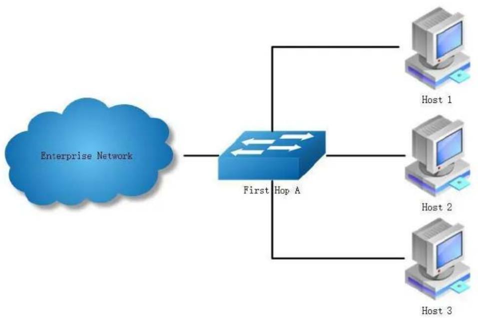
flowchart
graph TD
A["Enterprise Network"] --> B["First Hop A"]
B --> C["Host 1"]
B --> D["Host 2"]
B --> E["Host 3"]
Figure 16-21 Without VRRP
The Virtual Router Redundancy Protocol attempts to solve this problem by introducing the concept of a virtual router, composed of two or more VRRP routers on the same subnet. The concept of a virtual IP address is also introduced, which is the address that end hosts configure as their default gateway. Only one router (called the master) forward packets on the behalf of this IP address. In the event that the Master router fails, one of the other routers (Backup) assumes forwarding responsibility for it.
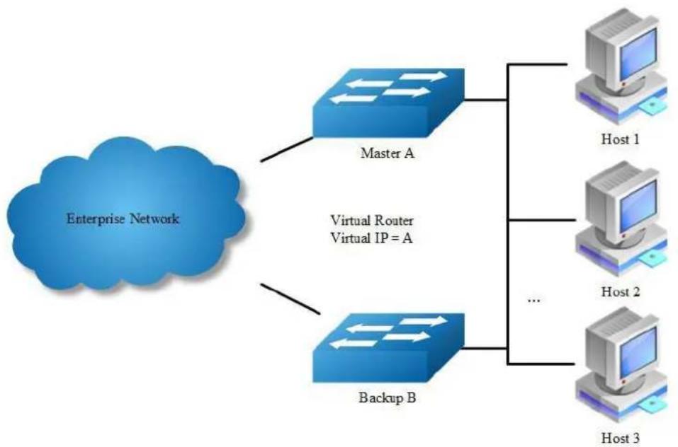
flowchart
graph TD
A["Enterprise Network"] --> B["Master A"]
A --> C["Backup B"]
B --> D["Host 1"]
B --> E["Host 2"]
B --> F["Host 3"]
C --> G["..."]
style A fill:#99CCFF,stroke:#333
style B fill:#66CCFF,stroke:#333
style C fill:#66CCFF,stroke:#333
style D fill:#99CCFF,stroke:#333
style E fill:#99CCFF,stroke:#333
style F fill:#99CCFF,stroke:#333
Figure 16-22 With VRRP
At first glance, the configuration outlined in might not seem very useful, as it doubles the cost and leaves one router idle at all times. This, however, can be avoided by creating two virtual routers and splitting the traffic between them.
16.12.2 Configuration
Configuring VRRP (One Virtual Router)
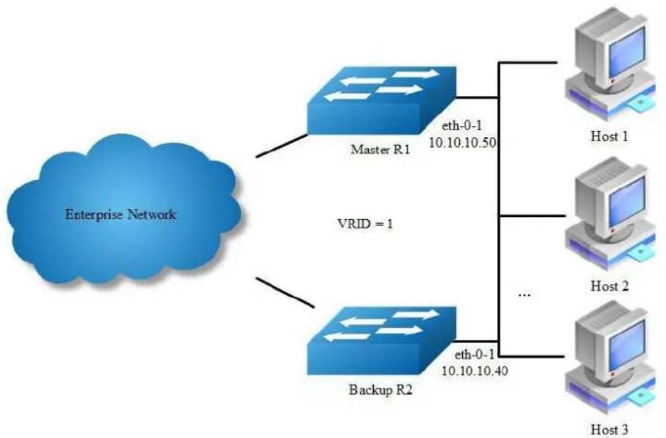
flowchart
graph TD
A["Enterprise Network"] --> B["Master R1"]
A --> C["Backup R2"]
B --> D["Host 1"]
B --> E["Host 2"]
B --> F["Host 3"]
C --> G["..."]
C --> H["eth-0-1 10.10.10.50"]
C --> I["eth-0-1 10.10.10.40"]
style A fill:#blue,stroke:#333
style B fill:#blue,stroke:#333
style C fill:#blue,stroke:#333
style D fill:#d4edda,stroke:#333
style E fill:#d4edda,stroke:#333
style F fill:#d4edda,stroke:#333
style G fill:#d4edda,stroke:#333
style H fill:#d4edda,stroke:#333
style I fill:#d4edda,stroke:#333
Figure 16-23 VRRP with one virtual router
In this configuration the end-hosts install a default route to the IP address of virtual router 1(VRID = 1) and both routers R1 and R2 run VRRP. R1 is configured to be the Master for virtual router 1 (VRID = 1) and R2 as a Backup for virtual router 1. If R1 fails, R2 will take over virtual router 1 and its IP addresses, and provide uninterrupted service for the hosts. Configuring only one virtual router, doubles the cost and leaves R2 idle at all times.
The following configuration should be operated on all devices if the device ID is not specified.
step 1 Enter the configure mode
Switch# configure terminal
step 2 Enter the interface configure mode and set the attributes of the interface
Interface configuration for R1:
Switch(config)# interface eth-0-1
Switch(config-if)# no switchport
Switch(config-if)# ip address 10.10.10.50/24
Switch(config-if)# no shutdown
Switch(config-if)# exit
Interface configuration for R2:
Switch(config)# interface eth-0-1
Switch(config-if)# no switchport
Switch(config-if)# ip address 10.10.10.40/24
Switch(config-if)# no shutdown
Switch(config-if)# exit
step 3 Create an instance of vrrp
Switch(config)# router vrrp 1
Switch(config-router)# virtual-ip 10.10.10.60
Switch(config-router)# interface eth-0-1
Switch(config-router)# preempt-mode true
Switch(config-router)# advertisement-interval 5
step 4 Set the priority (optional)
Set the priority on R2. R1 use the default value if the priority is not configured.
Switch(config-router)# priority 200
step 5 Enable vrrp and Exit the vrrp configure mode
Switch(config-router)# enable
Switch(config-router)# exit
step 6 Exit the configure mode
Switch(config)# end
step 7 Validation
Display the result on R1.
Switch# show vrrp
vrrp session count: 1
VRID <1>
State : Backup
Virtual IP : 10.10.10.60 (Not IP owner)
Interface : eth-0-1
VMAC : 0000.5e00.0101
VRF : Default
Advt timer : 5 second(s)
Preempt mode : TRUE
Conf pri : Unset Run pri : 100
Increased pri : 0
Master router ip : 10.10.10.40
Master priority : 200
Master advt timer : 5 second(s)
Master down timer : 16 second(s)
Preempt delay : 0 second(s)
Learn master mode : FALSE
Display the result on R2.
Switch# show vrrp
vrrp session count: 1
VRID <1>
State : Master
Virtual IP : 10.10.10.60 (Not IP owner)
Interface : eth-0-1
VMAC : 0000.5e00.0101
VRF : Default
Advt timer : 5 second(s)
Preempt mode : TRUE
Conf pri : 200 Run pri : 200
Increased pri : 0
Master router ip : 10.10.10.40
Master priority : 200
Master advt timer : 5 second(s)
Master down timer : 15 second(s)
Preempt delay : 0 second(s)
Learn master mode : FALSE
Configuring VRRP (Two Virtual Router)
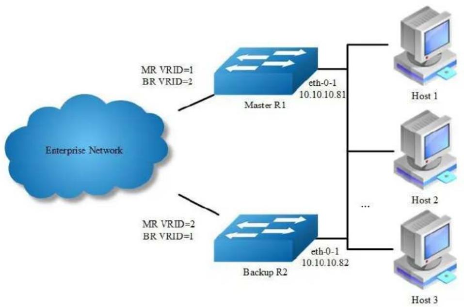
flowchart
graph TD
A["Enterprise Network"] --> B["Master R1"]
A --> C["Backup R2"]
B --> D["Host 1"]
B --> E["Host 2"]
B --> F["Host 3"]
C --> G["..."]
C --> H["..."]
B --> I["eth-0-1 10.10.10.81"]
C --> J["eth-0-1 10.10.10.82"]
B --> K["MR VRID=1 BR VRID=2"]
C --> L["MR VRID=2 BR VRID=1"]
Figure 16-24 VRRP with two virtual router
In the one virtual router example earlier, R2 is not backed up by R1. This example illustrates how to backup R2 by configuring a second virtual router.
In this configuration, R1 and R2 are two virtual routers and the hosts split their traffic between R1 and R2. R1 and R2 function as backups for each other.
The following configuration should be operated on all devices if the device ID is not specified.
step 1 Enter the configure mode
Switch# configure terminal
step 2 Enter the interface configure mode and set the attributes of the interface
Interface configuration for R1:
Switch(config)# interface eth-0-1
Switch(config-if)# no switchport
Switch(config-if)# ip address 10.10.10.81/24
Switch(config-if)# no shutdown
Switch(config-if)# exit
Interface configuration for R2:
Switch(config)# interface eth-0-1
Switch(config-if)# no switchport
Switch(config-if)# ip address 10.10.10.82/24
Switch(config-if)# no shutdown
Switch(config-if)# exit
step 3 Create an instance of vrrp
Configuring R1:
Switch(config)# router vrrp 1
Switch(config-router)# virtual-ip 10.10.10.81
Switch(config-router)# interface eth-0-1
Switch(config-router)# preempt-mode true
Switch(config-router)# advertisement-interval 5
Switch(config-router)# enable
Switch(config-router)# exit
Switch(config)# router vrrp 2
Switch(config-router)# virtual-ip 10.10.10.82
Switch(config-router)# interface eth-0-1
Switch(config-router)# priority 200
Switch(config-router)# preempt-mode true
Switch(config-router)# advertisement-interval 5
Switch(config-router)# enable
Switch(config-router)# exit
Configuring R2:
Switch(config)# router vrrp 1
Switch(config-router)# virtual-ip 10.10.10.81
Switch(config-router)# interface eth-0-1
Switch(config-router)# priority 200
Switch(config-router)# preempt-mode true
Switch(config-router)# advertisement-interval 5
Switch(config-router)# enable
Switch(config-router)# exit
Switch(config)# router vrrp 2
Switch(config-router)# virtual-ip 10.10.10.82
Switch(config-router)# interface eth-0-1
Switch(config-router)# preempt-mode true
Switch(config-router)# advertisement-interval 5
Switch(config-router)# enable
Switch(config-router)# exit
step 4 Exit the configure mode
Switch(config)# end
step 5 Validation
Display the result on R1.
Switch# show vrrp
vrrp session count: 2
VRID <1>
State : Master
Virtual IP : 10.10.10.81(IP owner)
Interface : eth-0-9
VMAC : 0000.5e00.0101
VRF : Default
Advt timer : 5 second(s)
Preempt mode : TRUE
Conf pri : Unset Run pri : 255
Increased pri : 0
Master router ip : 10.10.10.81
Master priority : 255
Master advt timer : 5 second(s)
Master down timer : 15 second(s)
Preempt delay : 0 second(s)
Learn master mode : FALSE
VRID <2>
State : Backup
Virtual IP : 10.10.10.82(Not IP owner)
Interface : eth-0-9
VMAC : 0000.5e00.0102
VRF : Default
Advt timer : 5 second(s)
Preempt mode : TRUE
Conf pri : 200 Run pri : 200
Increased pri : 0
Master router ip : 10.10.10.82
Master priority : 255
Master advt timer : 5 second(s)
Master down timer : 15 second(s)
Preempt delay : 0 second(s)
Learn master mode : FALSE
Display the result on R2.
Switch# show vrrp
vrrp session count: 2
VRID <1>
State : Backup
Virtual IP : 10.10.10.81(Not IP owner)
Interface : eth-0-9
VMAC : 0000.5e00.0101
VRF : Default
Advt timer : 5 second(s)
Preempt mode : TRUE
Conf pri : 200 Run pri : 200
Increased pri : 0
Master router ip : 10.10.10.81
Master priority : 255
Master advt timer : 5 second(s)
Master down timer : 15 second(s)
Preempt delay : 0 second(s)
Learn master mode : FALSE
VRID <2>
State : Master
Virtual IP : 10.10.10.82(IP owner)
Interface : eth-0-9
VMAC : 0000.5e00.0102
VRF : Default
Advt timer : 5 second(s)
Preempt mode : TRUE
Conf pri : Unset Run pri : 255
Increased pri : 0
Master router ip : 10.10.10.82
Master priority : 255
Master advt timer : 5 second(s)
Master down timer : 15 second(s)
Preempt delay : 0 second(s)
Learn master mode : FALSE
VRRP Circuit Failover
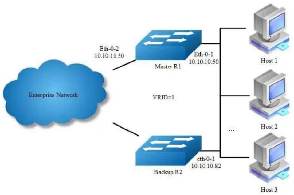
flowchart
graph TD
A["Enterprise Network"] --> B["Master R1"]
A --> C["Backup R2"]
B --> D["Host 1"]
B --> E["Host 2"]
B --> F["Host 3"]
C --> G["..."]
B --> H["VRID=1"]
C --> I["Eth-0-1 10.10.10.50"]
C --> J["Eth-0-2 10.10.11.50"]
Figure 16-25 VRRP Circuit Failover
The need for VRRP Circuit Failover arose because VRRPv2 was unable to track the gateway interface status. The VRRP Circuit Failover feature provides a dynamic failover of an entire circuit in the event that one member of the group fails. It introduces the concept of a circuit, where two or more Virtual Routers on a single system can be grouped. In the event that a failure occurs and one of the Virtual
Routers performs the Master to Backup transition, the other Virtual Routers in the group are notified and are forced into the Master to Backup transition, so that both incoming and outgoing packets are routed through the same gateway router, eliminating the problem for Firewall/NAT environments. The following scenario explains this feature.
To configure VRRP Circuit Failover, each circuit is configured to have a corresponding priority-delta value, which is passed to VRRP when a failure occurs. The priority of each Virtual Router on the circuit is decremented by the priority delta value causing the VR Master to VR Backup transition.
In this example, two routers R1 and R2 are configured as backup routers with different priorities. The priority-delta value is configured to be greater than the difference of both the priorities. R1 is configured to have a priority of 100 and R2 has a priority of 90. R1 with a greater priority is the Virtual Router Master. The priority-delta value is 20, greater than 10 (100 minus 90). On R1 when the external interface eth1 fails, the priority of R1 becomes 80 (100 minus 20). Since R2 has a greater priority (90) than R1, R2 becomes the VR Master and routing of packages continues without interruption.
When this VR Backup (R1) is up again, it regains its original priority (100) and becomes the VR Master again.
The following configuration should be operated on all devices if the device ID is not specified.
step 1 Enter the configure mode
Switch# configure terminal
step 2 Enter the interface configure mode and set the attributes of the interface
Interface configuration for R1:
Switch(config)# interface eth-0-1
Switch(config-if)# no switchport
Switch(config-if)# ip address 10.10.10.50/24
Switch(config-if)# no shutdown
Switch(config-if)# exit
Switch(config)# interface eth-0-2
Switch(config-if)# no switchport
Switch(config-if)# ip address 10.10.11.50/24
Switch(config-if)# no shutdown
Switch(config-if)# exit
Interface configuration for R2:
Switch(config)# interface eth-0-1
Switch(config-if)# no switchport
Switch(config-if)# ip address 10.10.10.40/24
Switch(config-if)# no shutdown
Switch(config-if)# exit
step 3 Create an track object to monitor the link state
Configuring R1:
Switch(config)# track 10 interface eth-0-2 linkstate
To get more information about track, please reference to the "Configuring Track" chapter.
step 4 Create an instance of vrrp
Configuring R1:
Switch(config)# router vrrp 1
Switch(config-router)# virtual-ip 10.10.10.1
Switch(config-router)# interface eth-0-1
Switch(config-router)# preempt-mode true
Switch(config-router)# advertisement-interval 5
Switch(config-router)# priority 100
Switch(config-router)# track 10 decrement 20
Switch(config-router)# enable
Configuring R2:
Switch(config)# router vrrp 1
Switch(config-router)# virtual-ip 10.10.10.1
Switch(config-router)# interface eth-0-1
Switch(config-router)# preempt-mode true
Switch(config-router)# advertisement-interval 5
Switch(config-router)# priority 90
Switch(config-router)# enable
step 5 Exit the configure mode
Switch(config)# end
step 6 Validation
Display the result on R1.
Switch# show vrrp
vrrp session count: 1
VRID <1>
State : Master
Virtual IP : 10.10.10.1(Not IP owner)
Interface : cth-0-9
VMAC : 0000.5e00.0101
VRF : Default
Advt timer : 5 second(s)
Preempt mode : TRUE
Conf pri : 100 Run pri : 100
Increased pri : 0
Track Object : 10
Decre pri : 20
Master router ip : 10.10.10.50
Master priority : 100
Master advt timer : 5 second(s)
Master down timer : 16 second(s)
Preempt delay : 0 second(s)
Learn master mode : FALSE
Display the result on R2.
Switch# show vrrp
vrrp session count: 1
VRID <1>
State : Backup
Virtual IP : 10.10.10.1 (Not IP owner)
Interface : eth-0-9
VMAC : 0000.5e00.0101
VRF : Default
Advt timer : 5 second(s)
Preempt mode : TRUE
Conf pri : 90 Run pri : 90
Increased pri : 0
Master router ip : 10.10.10.50
Master priority : 100
Master advt timer : 5 second(s)
Master down timer : 16 second(s)
Preempt delay : 0 second(s)
Learn master mode : FALSE
16.12.3 Application cases
N/A
16.13 Configuring Track
16.13.1 Overview
Function Introduction
Track is used for link the functional modules and monitor modules. Track builds a system structure with 3 levels: "functional modules - Track - monitor modules".
Track can shield the difference of the monitor modules and provide an unitized API for the functional modules.
The following monitor modules are supported:
IP SLA
interface states
bfd states
The following functional modules are supported:
Static route
VRRP
Track makes a communication for the functional modules and monitor modules. When link states or network performance is changed, the monitor modules can detect the event and notify the track module; therefore track will change its owner states and notify the related functional modules.
Principle Description
N/A
16.13.2 Configuration
Configuring IP SLA for interfaces in the VRF
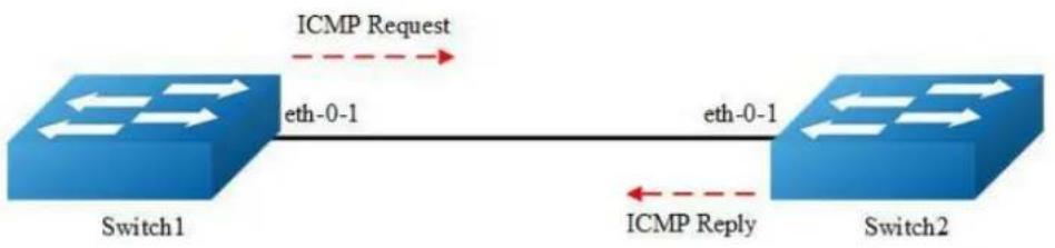
flowchart
graph LR
A["Switch1"] -->|ICMP Request eth-0-1| B["Switch2"]
B -->|ICMP Reply eth-0-1| A
Figure 16-26 IP SLA
IP SLA (Service Level Agreement) is a network performance measurement and diagnostics tool that uses active monitoring. Active monitoring is the generation of traffic in a reliable and predictable manner to measure network performance. Every IP SLA operation maintains an operation return-code value. This return code is interpreted by the tracking process. The return code can return OK, Over Threshold, and several other return codes. Different operations can have different return-code values, so only values common to all operation types are used. In IP SLA, use icmp echo to check state or reachability of a route.
The following configuration should be operated on all switches if the switch ID is not specified.
step 1 Enter the configure mode
Switch# configure terminal
step 2 Create a vrf instance
Switch(config)# ip vrf vpn1 Switch(config-vrf)# exit
step 3 Enter the interface configure mode and set the attributes of the interface
Interface configuration for Switch1:
Switch(config)# interface eth-0-1 Switch(config-if)# no switchport Switch(config-if)# no shutdown Switch(config-if)# ip vrf forwarding vpn1
Switch(config-if)# ip address 192.168.0.2/24
Switch(config-if)# exit
Interface configuration for Switch2:
Switch(config)# interface eth-0-1
Switch(config-if)# no switchport
Switch(config-if)# no shutdown
Switch(config-if)# ip vrf forwarding vpn1
Switch(config-if)# ip address 192.168.0.1/24
Switch(config-if)# exit
step 4 Create ip sla and set the attributes
Configuring Switch1:
Switch(config)# ip sla monitor 1
Switch(config-ipsla)# type icmp-echo 192.168.0.1
Switch(config-ipsla)# frequency 35
Switch(config-ipsla)# timeout 6
Switch(config-ipsla)# threshold 3000
Switch(config-ipsla)# ttl 65
Switch(config-ipsla)# tos 1
Switch(config-ipsla)# data-size 29
Switch(config-ipsla)# data-pattern abababab
Switch(config-ipsla)# fail-percent 90
Switch(config-ipsla)# packets-per-test 4
Switch(config-ipsla)# interval 9
Switch(config-ipsla)# statistics packet 10
Switch(config-ipsla)# statistics test 3
Switch(config-ipsla)# vrf vpnl
Switch(config-ipsla)# exit

NOTE
Parameters for ip sla:
frequency: Time between 2 probes. Valid range is 1-4800 second, default value is 60 seconds.
timeout:Timeout value for icmp reply. Valid range is 1-4800 second, default value is 5 seconds.
threshold: Timeout value for icmp threshold. Valid range is 1-4800000 millisecond, default value is 5000 millisecond.
packets-per-test: Packet number for each probe. Valid range is 1-10, default value is 3.
interval: Time between 2 packets. Valid range is 1-4800 second, default value is 6 seconds.
statistics packet: Packet number for statistics. Valid range is 0-1000, default value is 50.
statistics test probe number for statistics. Valid range is 0-10, default value is 5
step 5 Enable ip sla
Configuring Switch1:
Switch(config)# ip sla monitor schedule 1
step 6 Exit the configure mode
Switch(config)# end
step 7 Validation
Display the result on Switch1.
Switch# sho ip sla monitor 1
Entry 1
Type : Echo
Admin state : Disable
Destination address : 192.168.0.1
Frequency : 35s
Timeout : 6s
Threshold : 3000ms
Interval : 9s
Packet per test : 4
TTL : 65
TOS : 1
Data Size : 29 bytes
Fail Percent : 90%
Packet Item Cnt : 10
Test Item Cnt : 3
Vrf : vpn1
Return code : Unknown
Configuring IP SLA for Layer3 interfaces
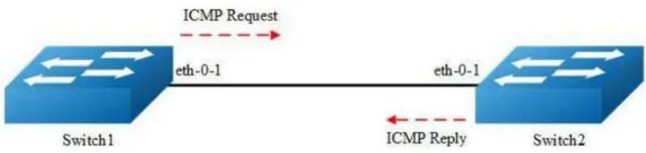
flowchart
graph LR
A["Switch1"] -->|ICMP Request eth-0-1| B["Switch2"]
B -->|ICMP Reply eth-0-1| A
Figure 16-27 IP SLA
The following configuration should be operated on all switches if the switch ID is not specified.:
step 1 Enter the configure mode
Switch# configure terminal
step 2 Enter the interface configure mode and set the attributes of the interface
Interface configuration for Switch1:
Switch(config)# interface eth-0-1
Switch(config-if)# no switchport
Switch(config-if)# no shutdown
Switch(config-if)# ip address 192.168.0.2/24
Switch(config-if)# exit
Interface configuration for Switch2:
Switch(config)# interface eth-0-1
Switch(config-if)# no switchport
Switch(config-if)# no shutdown
Switch(config-if)# ip address 192.168.0.1/24
Switch(config-if)# exit
step 3 Create ip sla and set the attributes
Configuring Switch1:
Switch(config)# ip sla monitor 1
Switch(config-ipsla)# type icmp-echo 192.168.0.1
Switch(config-ipsla)# frequency 10
Switch(config-ipsla)# timeout 5
Switch(config-ipsla)# exit
step 4 Enable ip sla
Configuring Switch1:
Switch(config)# ip sla monitor schedule 1
step 5 Exit the configure mode
Switch(config)# end
step 6 Validation
Display the result on Switch1.
Switch# show ip sla monitor
Entry 1
Type : Echo
Admin state : Enable
Destination address : 192.168.0.1
Frequency : 10 seconds
Timeout : 5 seconds
Threshold : 5 seconds
Running Frequency : 8 seconds
Return code : OK
Switch# ping 192.168.0.1
PING 192.168.0.1 (192.168.0.1) 56(84) bytes of data.
64 bytes from 192.168.0.1: icmp_seq=1 ttl=64 time=0.846 ms
64 bytes from 192.168.0.1: icmp_seq=2 ttl=64 time=0.643 ms
64 bytes from 192.168.0.1: icmp_seq=3 ttl=64 time=0.978 ms
64 bytes from 192.168.0.1: icmp_seq=4 ttl=64 time=0.640 ms
64 bytes from 192.168.0.1: icmp_seq=5 ttl=64 time=0.704 ms
Shutdown the interface eth-0-1 on Switch2.
Switch(config)# interface eth-0-1
Switch(config-if)# shutdown
Display the result on Switch1 again.
Switch# show ip sla monitor
Entry 1
Type : Echo
Admin state : Enable
Destination address : 192.168.0.1
Frequency : 10 seconds
Timeout : 5 seconds
Threshold : 5 seconds
Running Frequency : 9 seconds
Running Timeout : 4 seconds
Running Threshold : 4 seconds
Return code : Timeout
Configuring IP SLA for outgongin interface of static route
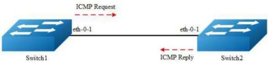
flowchart
graph LR
A["Switch1"] -->|ICMP Request eth-0-1| B["Switch2"]
B -->|ICMP Reply eth-0-1| A
Figure 16-28 IP SLA
The following configuration should be operated on all switches if the switch ID is not specified.:
step 1 Enter the configure mode
Switch# configure terminal
step 2 Enter the interface configure mode and set the attributes of the interface
Interface configuration for Switch1:
Switch(config)# interface eth-0-1
Switch(config-if)# no switchport
Switch(config-if)# no shutdown
Switch(config-if)# ip address 192.168.0.2/24n
Switch(config-if)# exit
Interface configuration for Switch2:
Switch(config)# interface eth-0-1
Switch(config-if)# no switchport
Switch(config-if)# no shutdown
Switch(config-if)# ip address 192.168.0.1/24
Switch(config-if)# exit
Switch(config)# interface loopback 1
Switch(config-if)# ip address 1.1.1.1/32
Switch(config-if)# exit
step 3 Create ip sla and set the attributes
Configuring Switch1:
Switch(config)# ip sla monitor 2
Switch(config-ipsla)# type icmp-echo 1.1.1.1
Switch(config-ipsla)# frequency 10
Switch(config-ipsla)# timeout 5
Switch(config-ipsla)# exit
step 4 Enable ip sla
Configuring Switch1:
Switch(config)# ip sla monitor schedule 2
step 5 Exit the configure mode
Switch(config)# end
step 6 Validation
Display the result on Switch1.
Switch# show ip sla monitor 2
Entry 2
Type : Echo
Admin state : Enable
Destination address : 1.1.1.1
Frequency : 10 seconds
Timeout : 5 seconds
Threshold : 5 seconds
Running Frequency : 1 seconds
Return code : Unreachable
Switch# ping 1.1.1.1
connect: Network is unreachable
Create a static route on Switch1
Switch#configure terminal
Switch(config)# ip route 1.1.1.1/32 192.168.0.1
Switch(config)# end
Display the result on Switch1 again.
Switch# ping 1.1.1.1
PING 1.1.1.1 (1.1.1.1) 56(84) bytes of data.
64 bytes from 1.1.1.1: icmp_seq=1 ttl=64 time=1.03 ms
64 bytes from 1.1.1.1: icmp_seq=2 ttl=64 time=1.63 ms
64 bytes from 1.1.1.1: icmp_seq=3 ttl=64 time=0.661 ms
64 bytes from 1.1.1.1: icmp_seq=4 ttl=64 time=0.762 ms
64 bytes from 1.1.1.1: icmp_seq=5 ttl=64 time=0.942 ms
Entry 2
Type : Echo
Admin state : Enable
Destination address : 1.1.1.1
Frequency : 10 seconds
Timeout : 5 seconds
Threshold : 5 seconds
Running Frequency : 8 seconds
Return code : OK
Configuring track interface linkstate
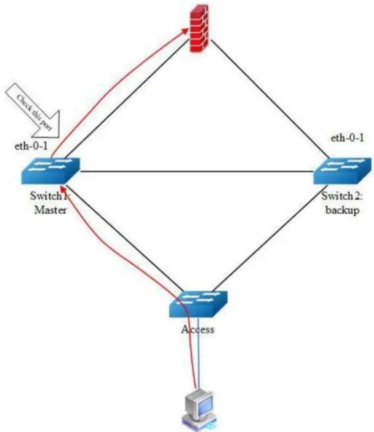
flowchart
graph TD
A["Switch 1: Master"] -->|eth-0-1| B["Switch 2: backup"]
B -->|eth-0-1| A
A -->|Access| C["Computer"]
B -->|Access| C
C -->|Check this port| A
Figure 16-29 Track interface
Before the introduction of track feature, the VRRP had a simple tracking mechanism that allowed you to track the interface link state only. If the link state of the interface went down, the VRRP priority of the router was reduced, allowing another VRRP router with a higher priority to become active. The Track feature separates the tracking mechanism from VRRP and creates a separate standalone tracking process that can be used by other processes in future. This feature allows tracking of other objects in addition to the interface link state. VRRP can now register its interest in tracking objects and then be notified when the tracked object changes state. TRACK is a separate standalone tracking process that can be used by other processes as well as VRRP. This feature allows tracking of other objects in addition to the interface link state.
Configuring Switch1:
step 1 Enter the configure mode
Switch# configure terminal
step 2 Create track and set the attributes
Switch(config)# track 1 interface eth-0-1 linkstate
Switch(config-track)# delay up 30
Switch(config-track)# delay down 30
Switch(config-track)# exit

NOTE
[]Parameters for track:
delay up: After the interface states is up, the track will wait for a cycle before restore the states. Valid range is 1-180 second. The default configuration is restore without delay.
delay down: After the interface states is down, the track will wait for a cycle before change the states. Valid range is 1-180 second. The default configuration is change without delay.
![AIRLIVE L3D-2TX4806-40GF - []Parameters for track: - 1](/content/2026/05/1140186/images/29be927edf1f5dc2e44809fa4eee4ca0b4b6ba0a78b9b9fa510ca0fd43bf3642.jpg)
NOTE
If the track is using bfd or ip sla, the “delay up” and “delay down”
is similar as using interface states.
step 3 Exit the configure mode
Switch(config)# end
step 4 Validation
Switch#show track
Track 2
Type : Interface Link state
Interface : eth-0-1
State : down
Delay up : 30 seconds
Delay down : 30 seconds
Configuring track ip sla reachability
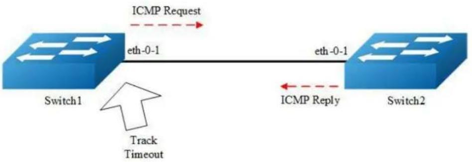
flowchart
graph LR
A["Switch1"] -->|ICMP Request eth-0-1| B["Switch2"]
B -->|ICMP Reply eth-0-1| A
A -->|Track Timeout arrow| B
Figure 16-30 Track ip sla
The following configuration should be operated on all switches if the switch ID is not specified.:
step 1 Enter the configure mode
Switch# configure terminal
step 2 Enter the interface configure mode and set the attributes of the interface
Interface configuration for Switch1:
Switch(config)# interface eth-0-1
Switch(config-if)# no switchport
Switch(config-if)# no shutdown
Switch(config-if)# ip address 192.168.0.2/24
Interface configuration for Switch2:
Switch(config)# interface eth-0-1
Switch(config-if)# no switchport
Switch(config-if)# no shutdown
Switch(config-if)# ip address 192.168.0.1/24
step 3 Create ip sla and enable it
Configuring Switch1:
Switch(config)# ip sla monitor 1
Switch(config-ipsla)# type icmp-echo 192.168.0.1
Switch(config-ipsla)# frequency 10
Switch(config-ipsla)# timeout 5
Switch(config-ipsla)# threshold 1
Switch(config-ipsla)# exit
Switch(config)# ip sla monitor schedule 1
step 4 Create track and set the attributes
Configuring Switch1:
Switch(config)# track 1 rtr 1 reachability
Switch(config-track)# delay up 30
Switch(config-track)# delay down 30
Switch(config-track)# exit
step 5 Exit the configure mode
Switch(config)# end
step 6 Validation
Switch#show track
Track 1
Type : Response Time Reporter(RTR) Reachability
RTR entry number : 1
State : up
Delay up : 30 seconds
Delay down : 30 seconds
Configuring track ip sla state
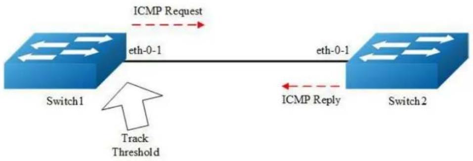
flowchart
graph LR
A["Switch1"] -->|ICMP Request| B["Switch2"]
B -->|eth-0-1| A
A -->|Track Threshold| B
B -->|ICMP Reply| A
Figure 16-31 Track ip sla
The following configuration should be operated on all switches if the switch ID is not specified.:
step 1 Enter the configure mode
Switch# configure terminal
step 2 Enter the interface configure mode and set the attributes of the interface
Interface configuration for Switch1:
Switch(config)# interface eth-0-1
Switch(config-if)# no switchport
Switch(config-if)# no shutdown
Switch(config-if)# ip address 192.168.0.2/24
Interface configuration for Switch2:
Switch(config)# interface eth-0-1
Switch(config-if)# no switchport
Switch(config-if)# no shutdown
Switch(config-if)# ip address 192.168.0.1/24
step 3 Create ip sla and enable it
Configuring Switch1:
Switch(config)# ip sla monitor 1
Switch(config-ipsla)# type icmp-echo 192.168.0.1
Switch(config-ipsla)# frequency 10
Switch(config-ipsla)# timeout 5
Switch(config-ipsla)# threshold 1
Switch(config-ipsla)# exit
Switch(config)# ip sla monitor schedule 1
step 4 Create track and set the attributes
Configuring Switch1:
Switch(config)# track 1 rtr 1 state
Switch(config-track)# delay up 30
Switch(config-track)# delay down 30
Switch(config-track)# exit
step 5 Exit the configure mode
Switch(config)# end
step 6 Validation
Switch# show track
Track 1
Type : Response Time Reporter(RTR) State
RTR entry number : 1
State : up
Delay up : 30 seconds
Delay down : 30 seconds
Configuring track bfd
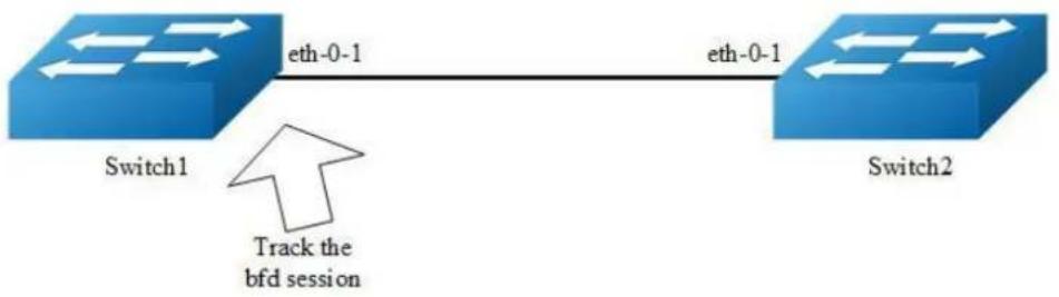
flowchart
graph LR
A["Switch1"] -->|eth-0-1| B["Switch2"]
B -->|eth-0-1| A
A -->|Track the bfd session| B
Figure 16-32 Track bfd
The following configuration should be operated on all switches if the switch ID is not specified.:
step 1 Enter the configure mode
Switch# configure terminal
step 2 Enter the interface configure mode and set the attributes of the interface
Interface configuration for Switch1:
Switch(config)# interface eth-0-1
Switch(config-if)# no switchport
Switch(config-if)# no shutdown
Switch(config-if)# ip address 9.9.9.1/24
Switch(config-if)# quit
Interface configuration for Switch2:
Switch(config)# interface eth-0-1
Switch(config-if)# no switchport
Switch(config-if)# no shutdown
Switch(config-if)# ip address 9.9.9.2/24
Switch(config-if)# quit
step 4 Create track and set the attributes
Configuring Switch1:
Switch(config)# track 1 bfd source interface eth-0-1 destination 9.9.9.2
Switch(config-track)# delay up 30
Switch(config-track)# delay down 30
Switch(config-track)# exit
Configuring Switch2:
Switch(config)# track 1 bfd source interface eth-0-1 destination 9.9.9.1
Switch(config-track)# delay up 30
Switch(config-track)# delay down 30
Switch(config-track)# exit
step 5 Exit the configure mode
Switch(config)# end
step 6 Validation
Display the result on Switch1.
Switch #show track
Track 1
Type : BFD state
Source interface : eth-0-1
Destination IP : 9.9.9.2
BFD Local discr : 1
State : up
Display the result on Switch2.
Switch # show track
Track 1
Type : BFD state
Source interface : eth-0-1
Destination IP : 9.9.9.1
BFD Local discr : 1
State : up
Configuring track for vrrp
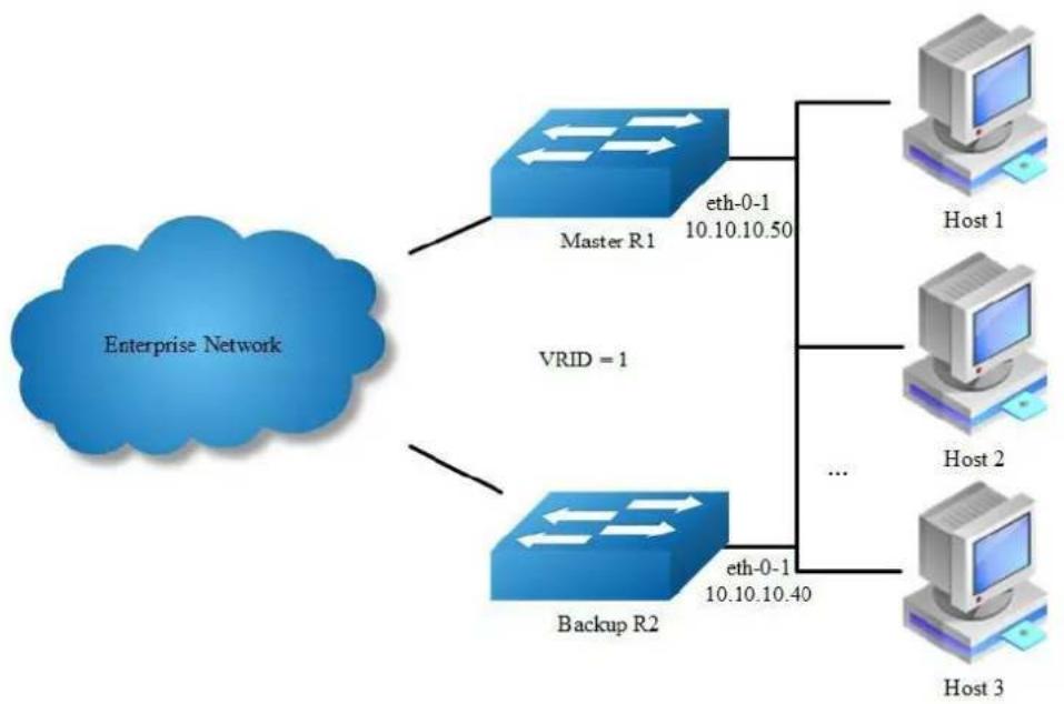
flowchart
graph TD
A["Enterprise Network"] --> B["Master R1"]
A --> C["Backup R2"]
B --> D["Host 1"]
B --> E["Host 2"]
B --> F["Host 3"]
C --> G["..."]
C --> H["eth-0-1 10.10.10.50"]
C --> I["eth-0-1 10.10.10.40"]
style A fill:#99CCFF,stroke:#333
style B fill:#66CCFF,stroke:#333
style C fill:#66CCFF,stroke:#333
style D fill:#99CCFF,stroke:#333
style E fill:#99CCFF,stroke:#333
style F fill:#99CCFF,stroke:#333
style G fill:#99CCFF,stroke:#333
style H fill:#99CCFF,stroke:#333
style I fill:#99CCFF,stroke:#333
Figure 16-33 VRRP Track
step 1 Check current configuration
Reference to chapter "Configuring VRRP" - "Configuring VRRP (One Virtual Router)" Display the configuration on R1.
interface eth-0-1
no switchport
ip address 10.10.10.50/24
!
router vrrp 1
interface eth-0-1
virtual-ip 10.10.10.60
advertisement-interval 5
enable
Display the configuration on R2.
interface eth-0-1
no switchport
ip address 10.10.10.40/24
!
router vrrp 1
interface eth-0-1
priority 200
virtual-ip 10.10.10.60
advertisement-interval 5
enable
step 2 Create track and set the attributes
Create track on Switch1
Switch(config)# track 1 interface eth-0-1 linkstate
Switch(config-track)# exit
step 3 Apply track for vrrp
Apply track on Switch1
Switch(config)# router vrrp 1
Switch(config-router)# disable
Switch(config-router)# track 1 decrement 30
Switch(config-router)# enable
step 4 Validation
Display the result on Switch1.
Switch# show vrrp
vrrp session count: 1
VRID <1>
State : Backup
Virtual IP : 10.10.10.60 (Not IP owner)
Interface : eth-0-9
VMAC : 0000.5e00.0101
VRF : Default
Advt timer : 5 second(s)
Preempt mode : TRUE
Conf pri : Unset Run pri : 100
Increased pri : 0
Track Object : 1
Decre pri : 30
Master router ip : 10.10.10.40
Master priority : 200
Master advt timer : 5 second(s)
Master down timer : 16 second(s)
Preempt delay : 0 second(s)
Learn master mode : FALSE
BFD session state : UNSET
Configuring track for static route

flowchart
graph LR
A["Switch 1"] -->|eth-0-1\n192.168.1.10| B["Switch 2"]
B -->|eth-0-1\n192.168.1.11| A
Figure 16-34 Static Route Track
The following configuration should be operated on all switches if the switch ID is not specified.:
step 1 Enter the configure mode
Switch# configure terminal
step 2 Enter the interface configure mode and set the attributes of the interface
Interface configuration for Switch1:
Switch(config)#interface eth-0-1
Switch(config-if)# no switchport
Switch(config-if)# no shutdown
Switch(config-if)# ip address 192.168.1.10/24
Switch(config-if)# exit
Interface configuration for Switch2:
Switch(config)#interface eth-0-1
Switch(config-if)# no switchport
Switch(config-if)# no shutdown
Switch(config-if)# ip address 192.168.1.11/24
Switch(config-if)# exit
step 3 Create ip sla and enable it
Configuring Switch1:
Switch(config)# ip sla monitor 1
Switch(config-ipsla)# type icmp-echo 192.168.1.11
Switch(config-ipsla)# exit
Switch(config)# ip sla monitor schedule 1
step 4 Create track and set the attributes
Configuring Switch1:
Switch(config)# track 1 rtr 1 reachability
Switch(config-track)# exit
step 5 Apply track for static route
Switch(config)#ip route 10.10.10.0/24 192.168.1.11 track 1
step 6 Exit the configure mode
Switch(config)# end
step 7 Validation
Display the result on Switch1.
Switch# show ip sla monitor 1
Entry 1
Type : Echo
Admin state : Enable
Destination address : 192.168.1.11
Frequency : 60 seconds
Timeout : 5 seconds
Threshold : 5 seconds
Running Frequency : 49 seconds
Return code : OK
Switch# show track 1
Track 1
Type : Response Time Reporter(RTR) Reachability
RTR entry number : 1
State : up
Switch# show ip route static
S 10.10.10.0/24 [1/0] via 192.168.1.11, eth-0-1
Shutdown the interface eth-0-1 on Switch2.
Switch(config)# interface eth-0-1
Switch(config-if)# shutdown
Display the result on Switch1 again.
Switch# show ip sla monitor 1
Entry 1
Type : Echo
Admin state : Enable
Destination address : 192.168.1.11
Frequency : 60 seconds
Timeout : 5 seconds
Threshold : 5 seconds
Running Frequency : 8 seconds
Return code : Timeout
Switch# show track 1
Track 1
Type : Response Time Reporter(RTR) Reachability
RTR entry number : 1
State : down
Switch# show ip route static
Switch#
16.13.3 Application cases
N/A
16.14 Configuring IP BFD
16.14.1 Overview
Function Introduction
An increasingly important feature of networking equipment is the rapid detection of communication failures between adjacent systems, in order to more quickly establish alternative paths. Detection can come fairly quickly in certain circumstances when data link hardware comes into play (such as Synchronous Optical Network (SONET) alarms). However, there are media that do not provide this kind of signaling (such as Ethernet), and some media may not detect certain kinds of failures in the path, for example, failing interfaces or forwarding engine components.
Networks use relatively slow “Hello” mechanisms, usually in routing protocols, to detect failures when there is no hardware signaling to help out. The time to detect failures (“Detection Times”) available in the existing protocols is no better than a second, which is far too long for some applications and represents a great deal of lost data at gigabit rates. Furthermore, routing protocol Hellos are of no help when those routing protocols are not in use, and the semantics of detection are subtly different - they detect a failure in the path between the two routing protocol engines.
The goal of Bidirectional Forwarding Detection (BFD) is to provide low-overhead, short-duration detection of failures in the path between adjacent forwarding engines, including the interfaces, data link(s), and, to the extent possible, the forwarding engines themselves.
An additional goal is to provide a single mechanism that can be used for aliveness detection over any media, at any protocol layer, with a wide range of Detection Times and overhead, to avoid a proliferation of different methods.

NOTE
If ethernet CFM mep is configured on an physical port and CFM LM is enabled, at the same time, IP BFD is configured on an vlan interface and the former physical port is a member of the vlan, IP BFD can't work normally. If CFM LM is disabled, IP BFD can work normally.
16.14.2 Configuration
Configuring BFD single-hop
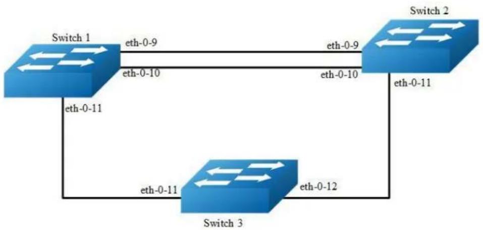
flowchart
graph TD
A["Switch 1"] -->|eth-0-9| B["Switch 2"]
B -->|eth-0-11| C["Switch 3"]
C -->|eth-0-12| B
A -->|eth-0-10| B
B -->|eth-0-11| C
C -->|eth-0-11| A
Figure 16-35 BFD single hop
This topology contains 3 BFD sessions, one based on a static configuration and bound to static routes, one based on an OSPF, and one based on a bfd linked to the vrrp.
The following configuration should be operated on all switches if the switch ID is not specified.
step 1 Enter the configure mode
Switch# configure terminal
step 2 Enter the interface configure mode and set the attributes of the interface
Interface configuration for Switch1:
Switch(config)# interface eth-0-9
Switch(config-if)# no switchport
Switch(config-if)# no shutdown
Switch(config-if)# ip address 9.9.9.1/24
Switch(config-if)# bfd interval mintx 3 minrx 3 multiplier 3
Switch(config-if)# exit
Switch(config)# interface eth-0-10
Switch(config-if)# no switchport
Switch(config-if)# no shutdown
Switch(config-if)# ip address 10.10.10.1/24
Switch(config-if)# bfd interval mintx 3 minrx 3 multiplier 3
Switch(config)# interface eth-0-11
Switch(config-if)# no switchport
Switch(config-if)# no shutdown
Switch(config-if)# ip address 11.11.11.1/24
Switch(config-if)# exit
Interface configuration for Switch2:
Switch(config)# interface eth-0-9
Switch(config-if)# no switchport
Switch(config-if)# no shutdown
Switch(config-if)# ip address 9.9.9.2/24
Switch(config-if)# bfd interval mintx 3 minrx 3 multiplier 3
Switch(config-if)# exit
Switch(config)# interface eth-0-10
Switch(config-if)# no switchport
Switch(config-if)# no shutdown
Switch(config-if)# ip address 10.10.10.2/24
Switch(config-if)# bfd interval mintx 3 minrx 3 multiplier 3
Switch(config-if)# ip ospf bfd
Switch(config-if)# exit
Switch(config)# interface eth-0-11
Switch(config-if)# no switchport
Switch(config-if)# no shutdown
Switch(config-if)# ip address 11.11.11.2/24
Switch(config-if)# exit
Interface configuration for Switch3:
Switch(config)# interface eth-0-11
Switch(config-if)# no shutdown
Switch(config-if)# exit
Switch(config)# interface eth-0-12
Switch(config-if)# no shutdown
Switch(config-if)# exit
step 3 Configuring ospf
Configuring Switch1:
Switch(config)# router ospf
Switch(config-router)# network 10.10.10.0/24 area 0
Switch(config-router)# exit
Configuring Switch3:
Switch(config)# router ospf
Switch(config-router)# network 10.10.10.0/24 area 0
Switch(config-router)# exit
step 4 Configuring VRRP
Configuring Switch1:
Switch(config)#router vrrp 1
Switch(config-router)#virtual-ip 11.11.11.100
Switch(config-router)#interface eth-0-11
Switch(config-router)# bfd 11.11.11.2
Switch(config-router)# enable
Switch(config-router)# exit
Configuring Switch2:
Switch(config)#router vrrp 1
Switch(config-router)#virtual-ip 11.11.11.100
Switch(config-router)#interface eth-0-11
Switch(config-router)# bfd 11.11.11.1
Switch(config-router)# enable
Switch(config-router)# exit
step 5 Configuring static route
Configuring Switch1:
Switch(config)# bfd test peer-ip 9.9.9.2 interface eth-0-9 auto
Switch(config)# ip route 1.1.1.0/24 9.9.9.2 bind bfd test
Configuring Switch2:
Switch(config)# bfd test peer-ip 9.9.9.1 interface eth-0-9 auto
Switch(config)# ip route 2.2.2.0/24 9.9.9.1 bind bfd test
step 6 Exit the configure mode
Switch(config)# end
step 7 Validation
Switch# show bfd session
abbreviation:
LD: local Discriminator. RD: Discriminator
S: single hop session. M: multi hop session.
SD: Static Discriminator. DD: Dynamic Discriminator
A: Admin down. D:down. I:init. U:up.
LD RD TYPE ST UP-Time Remote-Addr vrf
1 1 S-DD U 00:01:05 9.9.9.2 default
2 2 S-DD U 00:00:25 10.10.10.2 default
3 3 S-DD U 00:00:25 11.11.11.2 default
Number of Sessions: 3
Switch# show bfd session
abbreviation:
LD: local Discriminator. RD: Discriminator
S: single hop session. M: multi hop session.
SD: Static Discriminator. DD: Dynamic Discriminator
A: Admin down. D:down. I:init. U:up.
LD RD TYPE ST UP-Time Remote-Addr vrf
1 1 S-DD U 00:01:27 9.9.9.1 default
2 2 S-DD U 00:00:46 10.10.10.1 default
3 3 S-DD U 00:00:25 11.11.11.3 default
Number of Sessions: 3
Configuring BFD multi-hop
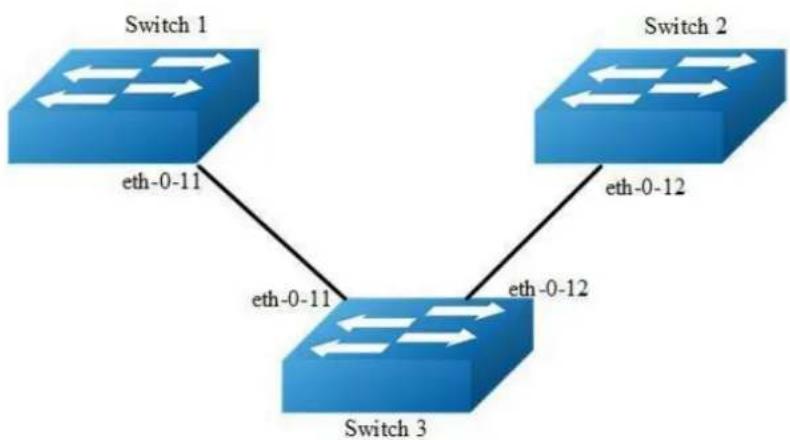
flowchart
graph TD
A["Switch 1"] -->|eth-0-11| B["Switch 3"]
C["Switch 2"] -->|eth-0-12| B["Switch 3"]
B["Switch 3"] -->|eth-0-12| C["Switch 2"]
Figure 16-36 BFD multi hop
This topology and configuration is for one BFD session which is based on static multiple bfd for static route.
The following configuration should be operated on all switches if the switch ID is not specified.
step 1 Enter the configure mode
Switch# configure terminal
step 2 Enter the interface configure mode and set the attributes of the interface
Interface configuration for Switch1:
Switch(config)# interface eth-0-11
Switch(config-if)# no switchport
Switch(config-if)# no shutdown
Switch(config-if)# ip address 11.11.11.1/24
Switch(config-if)# exit
Interface configuration for Switch3:
Switch(config)# interface eth-0-11
Switch(config-if)# no switchport
Switch(config-if)# no shutdown
Switch(config-if)# ip address 11.11.11.2/24
Switch(config-if)# exit
Switch(config)#interface eth-0-12
Switch(config-if)#no switchport
Switch(config-if)#no shutdown
Switch(config-if)#ip address 12.12.12.1/24
Switch(config-if)#exit
Interface configuration for Switch2:
Switch(config)# interface eth-0-12
Switch(config-if)# no switchport
Switch(config-if)# no shutdown
Switch(config-if)# ip address 12.12.12.2/24
Switch(config-if)# exit
step 3 Configuring static route
Configuring Switch1:
Switch1(config)# ip route 12.12.12.2/24 11.11.11.2
Switch1(config)# bfd test peer-ip 12.12.12.2 source-ip 11.11.11.1 local 10 remote 20
Switch1(config)# ip route 192.168.1.1/24 12.12.12.2 bind bfd test
Configuring Switch2:
Switch2(config)#ip route 11.11.11.1/24 12.12.12.1
Switch2(config)#bfd test peer-ip 11.11.11.1 source-ip 12.12.12.2 local 20 remote 10
Switch2(config)#ip route 2.2.2.2/24 11.11.11.1 bind bfd test
step 4 Exit the configure mode
Switch(config)# end
step 5 Validation
Display the result on Switch1:
Switch# show bfd session
abbreviation:
LD: local Discriminator. RD: Discriminator
S: single hop session. M: multi hop session.
SD: Static Discriminator. DD: Dynamic Discriminator
A: Admin down. D:down. I:init. U:up.
====================
LD RD TYPE ST UP-Time Remote-Addr vrf
10 20 S-SD U 00:01:27 12.12.12.2 default
Display the result on Switch2:
Switch# show bfd session
abbreviation:
LD: local Discriminator. RD: Discriminator
S: single hop session. M: multi hop session.
SD: Static Discriminator. DD: Dynamic Discriminator
A: Admin down. D:down. I:init. U:up.
====================
LD RD TYPE ST UP-Time Remote-Addr vrf
20 10 S-SD U 00:01:27 11.11.11.1 default
16.14.3 Application cases
N/A
16.15 Configuring VARP
16.15.1 Overview
Function Introduction
Virtual ARP (VARP) allows multiple switches to simultaneously route packets with the same destination MAC address. Each switch is configured with the same virtual MAC address for the L3 interfaces configured with a virtual IP address. In MLAG configurations, VARP is preferred over VRRP because VARP working on active-active mode without traffic traverse peer link.
For ARP and GARP requests to virtual IP address, VARP will use the virtual MAC address to reply. The virtual MAC address is only used in the destination field of inbound packets and never used in the source field of outbound packets. Topology
Principle Description
N/A
16.15.2 Configuration
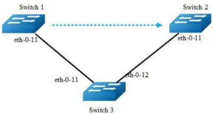
flowchart
graph TD
A["Switch 1"] -->|eth-0-11| B["Switch 3"]
B -->|eth-0-12| C["Switch 2"]
C -->|eth-0-11| A
Figure 16-37 VARP with MALG
The following configuration should be operated on all devices if the device ID is not specified.
step 1 Enter the configure mode
Switch# configure terminal
step 2 Set the virtual-router mac address
Switch(config)# ip virtual-router mac a.a.a
step 3 Enter the vlan configure mode and create the vlan
Switch(config)# vlan database
Switch(config-vlan)# vlan 2
Switch(config-vlan)# exit
step 4 Enter the interface configure mode and set the attributes of the interface
Switch(config)# interface eth-0-11
Switch(config-if)# switchport access vlan 2
Switch(config-if)# no shutdown
Switch(config-if)# exit
step 5 Create the vlan interface and set ip and virtual router ip
Configuring Switch1:
Switch(config)# interface vlan 2
Switch(config-if)# ip address 10.10.10.1/24
Switch(config-if)# ip virtual-router address 10.10.10.254
Switch(config-if)# exit
Configuring Switch2:
Switch2(config-if)# interface vlan 2
Switch2(config-if)# ip address 10.10.10.2/24
Switch2(config-if)# ip virtual-router address 10.10.10.254
Switch(config-if)# exit
step 6 Exit the configure mode
Switch(config)# end
step 7 Validation
Display the result on Switch1.
Switch# show ip arp
Protocol Address Age (min) Hardware Addr Interface
Internet 10.10.10.1 - cef0.12da.8100 vlan2
Internet 10.10.10.254 - 000a.000a.000a vlan2
Display the result on Switch2.
Switch# show ip arp
Protocol Address Age (min) Hardware Addr Interface
Internet 10.10.10.2 - 66d1.4c26.e100 vlan2
Internet 10.10.10.254 - 000a.000a.000a vlan2
16.15.3 Application cases
N/A
16.16 Configuring UDP Helper
16.16.1 Overview
Function Introduction
The main function of UDP helper is to relay and forward the specified UDP message in IP broadcast packet, convert the specified UDP message in IP broadcast packet into unicast packet and send it to the specified server, it plays a role of relay.
After enabling the UDP helper function, the device will make a judgement on the destination port number of the received broadcast UDP packet. If the packet whose destination port number matches the port number configured by the UDP helper, it will copy it and modify the the destination IP address of packet header and sent to the designated server.
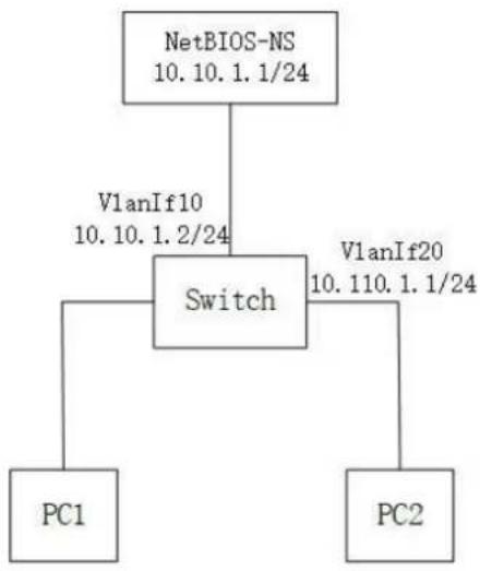
flowchart
graph TD
A["NetBIOS-NS\n10.10.1.1/24"] --> B["Switch"]
B --> C["PC1"]
B --> D["PC2"]
B --> E["VlanIf10\n10.10.1.2/24"]
B --> F["VlanIf20\n10.110.1.1/24"]
Figure 16-38 UDP-Helper configuration
The default 6 UDP destination port:
Protocol | UDP destination port |
| DNS (Domain Name System) | 53 | |NetBIOS-DS (NetBIOS Datagram Service) | 138 | |NetBIOS-NS (NetBIOS Name Service) | 137 | |TACACS (Terminal Access Controller Access Control System) | 49 | |TFTP (Trivial File Transfer Protocol) | 69 | |Time Service | 37 |
Principle Description
16.16.2 Configuration
step 1 Enter the configure mode
Switch# configure terminal
step 2 Enable UDP Helper
Switch(config)# ip udp-helper enable
step 3 Configure the IP address and UDP Helper Server IP address on interface
Switch(config)# vlan database
Switch(config-vlan)# vlan 10,20
Switch(config-vlan)# exit
Switch(config)# interface eth-0-1
Switch(config-if)# switchport mode access
Switch(config-if)# switchport access vlan 20
Switch(config-if)# exit
Switch(config)# interface eth-0-2
Switch(config-if)# switchport mode access
Switch(config-if)# switchport access vlan 10
Switch(config-if)# exit
Switch(config)# interface vlan 20
Switch(config-if)# ip address 10.110.1.1/24
Switch(config-if)# ip udp-helper server 10.10.1.1
Switch(config-if)# exit
Switch(config)# interface vlan 10
Switch(config-if)# ip address 10.10.1.2/24
step 4 configure the ARP
Switch(config)# arp 10.10.1.1 0.0.1
step 5 Exit the configure mode
Switch(config)# end
step 6 Validation
To display the UDP Helper configuration, use following privileged EXEC commands.
Switch# show ip udp-helper server
Interface Server IP Packet Received Packet Dropped

16.16.3 Application cases
N/A
17 DataCenter Configuration Guide
17.1 Configuring VXLAN
17.1.1 Overview
Function Introduction
Virtual Extensible LAN (VXLAN) is a networking technology that encapsulates MAC-based Layer 2 Ethernet frames within Layer 3 UDP packets to aggregate and tunnel multiple layer 2 networks across a Layer 3 infrastructure. VXLAN scales up to 16 million logical networks and supports layer 2 adjacency across IP networks. Multicast transmission architecture is used for broadcast/multicast/unknown packets.
Principle Description
N/A
17.1.2 Configuration
Vxlan Configuration
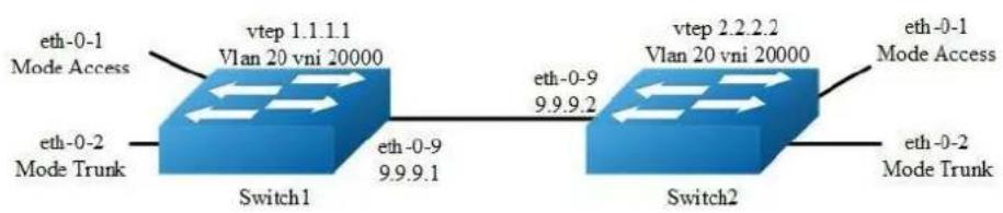
flowchart
graph LR
A["Switch1"] -->|eth-0-9 9.9.9.1| B["Switch2"]
B -->|eth-0-1 Mode Access| A
A -->|eth-0-2 Mode Trunk| A
B -->|eth-0-2 Mode Trunk| B
A -->|vtep 1.1.1.1 Vlan 20 vni 20000| A
B -->|vtep 2.2.2.2 Vlan 20 vni 20000| B
Figure 17-1 Vxlan
In the following example, switch1 and switch2 are connected via layer 3 route. The traffic of vlan 20 are encapsulated in vni 20000, in order to pass through the layer 3 networks.
The following configuration should be operated on all switches if the switch ID is not specified.
step 1 Enter the configure mode
Switch# configure terminal
step 2 Enter the vlan configure mode and create vlan, enable overlay for each vlan
Switch(config)# vlan database
Switch(config-vlan)# vlan 20
Switch(config-vlan)# vlan 20 overlay enable
Switch(config-vlan)# exit
step 3 Enter the interface configure mode and set the attributes of the interface
Interface configuration for Switch1:
Switch(config)# interface eth-0-1
Switch(config-if)# switchport access vlan 20
Switch(config-if)# no shutdown
Switch(config-if)# exit
Switch(config)# interface eth-0-2
Switch(config-if)# switchport mode trunk
Switch(config-if)# switchport trunk allowed vlan add 20
Switch(config-if)# no shutdown
Switch(config-if)# exit
Switch(config)# interface eth-0-9
Switch(config-if)# no switchport
Switch(config-if)# ip address 9.9.9.1/24
Switch(config-if)# overlay uplink enable
Switch(config-if)# no shutdown
Switch(config-if)# exit
Switch(config)# interface loopback0
Switch(config-if)# ip address 1.1.1.1/32
Switch(config-if)# exit
Interface configuration for Switch2:
Switch(config)# interface eth-0-1
Switch(config-if)# switchport access vlan 20
Switch(config-if)# no shutdown
Switch(config-if)# exit
Switch(config)# interface eth-0-2
Switch(config-if)# switchport mode trunk
Switch(config-if)# switchport trunk allowed vlan add 20
Switch(config-if)# no shutdown
Switch(config-if)# exit
Switch(config)# interface eth-0-9
Switch(config-if)# no switchport
Switch(config-if)# ip address 9.9.9.2/24
Switch(config-if)# overlay uplink enable
Switch(config-if)# no shutdown
Switch(config-if)# exit
Switch(config)# interface loopback0
Switch(config-if)# ip address 2.2.2.2/32
Switch(config-if)# exit
Step 4 Create a static route
Configuring Switch1:
Switch(config)# ip route 2.2.2.0/24 9.9.9.2
Configuring Switch2:
Switch(config)# ip route 1.1.1.0/24 9.9.9.1
Step 5 Set attributes for overlay
Configuring Switch1:
Switch(config)# overlay
Switch(config-overlay)# source 1.1.1.1
Switch(config-overlay)# remote-vtep 1 ip-address 2.2.2.2 type vxlan
Switch(config-overlay)# vlan 20 vni 20000
Switch(config-overlay)# vlan 20 remote-vtep 1
Switch(config-overlay)# exit
Configuring Switch2:
Switch(config)# overlay
Switch(config-overlay)# source 2.2.2.2
Switch(config-overlay)# remote-vtep 1 ip-address 1.1.1.1 type vxlan
Switch(config-overlay)# vlan 20 vni 20000
Switch(config-overlay)# vlan 20 remote-vtep 1
Switch(config-overlay)# exit
step 6 Exit the configure mode
Switch(config)# end
step 7 Validation
Display the result on Switch1:
Switch# show overlay vlan 20
ECMP Mode : Normal
Source VTEP : 1.1.1.1
VLAN ID : 20
VNI : 20000
EVPN Tunnel Data-fdb Learning : Enable
Remote VTEP NUM : 1
Index: 1, Ip address: 2.2.2.2, Source ip: 1.1.1.1, Type: VxLAN, Protocol:
Static
DVR Gateway NUM: 0
Display the result on Switch2:
Switch# show overlay vlan 20
ECMP Mode : Normal
Source VTEP : 2.2.2.2
VLAN ID : 20
VNI : 20000
EVPN Tunnel Data-fdb Learning : Enable
Remote VTEP NUM : 1
Index: 1, Ip address: 1.1.1.1, Source ip: 2.2.2.2, Type: VxLAN, Protocol:
Static
DVR Gateway NUM: 0
Configuring VXLAN Routing
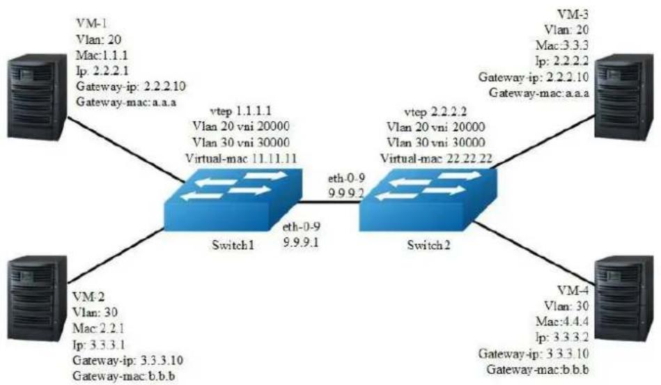
flowchart
graph TD
A["VM-1\nVlan: 20\nMac:1.1.1\nIp: 2.2.2.1\nGateway-ip: 2.2.2.10\nGateway-mac:a.a.a"] --> B["Switch1"]
C["VM-2\nVlan: 30\nMac:2.2.1\nIp: 3.3.3.1\nGateway-ip: 3.3.3.10\nGateway-mac:b.b.b"] --> B
D["VM-3\nVlan: 20\nMac:3.3.3\nIp: 2.2.2.2\nGateway-ip: 2.2.2.10\nGateway-mac:a.a.a"] --> E["Switch2"]
F["VM-4\nVlan: 30\nMac:4.4.4\nIp: 3.3.3.2\nGateway-ip: 3.3.3.10\nGateway-mac:b.b.b"] --> E
B -->|vtep 1.1.1.1\nVlan 20 vni 20000\nVlan 30 vni 30000\nVirtual-mac 11.11.11| B
B -->|eth-0.9\n9.9.9.1| E
E -->|vtep 2.2.2.2\nVlan 20 vni 20000\nVlan 30 vni 30000\nVirtual-mac 22.22.22| E
Figure 17-2 Vxlan
In the following example, VM-1 & VM-3 are encapsulated in same vni to make up the distributed route via vxlan; VM-2 & VM-4 are encapsulated in another vni to make up the distributed route via vxlan.
The following configuration should be operated on all switches if the switch ID is not specified.
step 1 Enter the configure mode
Switch# configure terminal
step 2 Enter the vlan configure mode and create vlan, enable overlay for each vlan
Switch(config)# vlan database
Switch(config-vlan)# vlan 20,30
Switch(config-vlan)# vlan 20 overlay enable
Switch(config-vlan)# vlan 30 overlay enable
Switch(config-vlan)# exit
step 3 Create a vrf instance
step 4 Create the layer 3 interface and set the ip address
Configuring Switch1:
Switch(config)# interface vlan 20
Switch(config-if)# ip vrf forwarding tenant
Switch(config-if)# ip address 2.2.2.111/24
Switch(config-if)# exit
Switch(config)# interface vlan 30
Switch(config-if)# ip vrf forwarding tenant
Switch(config-if)# ip address 3.3.3.111/24
Switch(config-if)# exit
Configuring Switch2:
Switch(config)# interface vlan 20
Switch(config-if)# ip vrf forwarding tenant
Switch(config-if)# ip address 2.2.2.222/24
Switch(config-if)# exit
Switch(config)# interface vlan 30
Switch(config-if)# ip vrf forwarding tenant
Switch(config-if)# ip address 3.3.3.222/24
Switch(config-if)# exit
step 5 Enter the interface configure mode and set the attributes of the interface
Switch(config)# interface eth-0-1
Switch(config-if)# switchport mode trunk
Switch(config-if)# switchport trunk allowed vlan add 20
Switch(config-if)# no shutdown
Switch(config-if)# exit
Switch(config)# interface eth-0-2
Switch(config-if)# switchport mode trunk
Switch(config-if)# switchport trunk allowed vlan add 30
Switch(config-if)# no shutdown
Switch(config-if)# exit
Configuring Switch1:
Switch(config)# interface eth-0-9
Switch(config-if)# no switchport
Switch(config-if)# ip address 9.9.9.1/24
Switch(config-if)# overlay uplink enable
Switch(config-if)# no shutdown
Switch(config-if)# exit
Switch(config)# interface loopback0
Switch(config-if)# ip address 1.1.1.1/32
Switch(config-if)# exit
Configuring Switch2:
Switch(config)# interface eth-0-9
Switch(config-if)# no switchport
Switch(config-if)# ip address 9.9.9.2/24
Switch(config-if)# overlay uplink enable
Switch(config-if)# no shutdown
Switch(config-if)# exit
Switch(config)# interface loopback0
Switch(config-if)# ip address 2.2.2.2/32
Switch(config-if)# exit
Step 6 Set attributes for overlay
Configuring Switch1:
Switch(config)# overlay
Switch(config-overlay)# source 1.1.1.1
Switch(config-overlay)# remote-vtep 1 ip-address 2.2.2.2 type vxlan
Switch(config-overlay)# remote-vtep 1 virtual-mac 22.22.22
Switch(config-overlay)# vlan 20 vni 20000
Switch(config-overlay)# vlan 30 vni 30000
Switch(config-overlay)# vlan 20 remote-vtep 1
Switch(config-overlay)# vlan 30 remote-vtep 1
Switch(config-overlay)# vlan 20 gateway-mac a.a.a
Switch(config-overlay)# vlan 30 gateway-mac b.b.b
Switch(config-overlay)# exit
Configuring Switch2:
Switch(config)# overlay
Switch(config-overlay)# source 2.2.2.2
Switch(config-overlay)# remote-vtep 1 ip-address 1.1.1.1 type vxlan
Switch(config-overlay)# remote-vtep 1 virtual-mac 11.11.11
Switch(config-overlay)# vlan 20 vni 20000
Switch(config-overlay)# vlan 30 vni 30000
Switch(config-overlay)# vlan 20 remote-vtep 1
Switch(config-overlay)# vlan 20 remote-vtep 1
Switch(config-overlay)# vlan 20 gateway-mac a.a.a
Switch(config-overlay)# vlan 30 gateway-mac b.b.b
Switch(config-overlay)# exit
step 7 Create a static routes and vxlan routes
Configuring Switch1:
Switch(config)# ip route 2.2.2.0/24 9.9.9.2
Switch(config)# ip route vrf tenant 2.2.2.2/32 remote-vtep 1 vni 20000 inner-macda 3.3.3
Switch(config)# ip route vrf tenant 3.3.3.2/32 remote-vtep 1 vni 30000 inner-macda 4.4.4
Configuring Switch2:
Switch(config)# ip route 1.1.1.0/24 9.9.9.1
Switch(config)# ip route vrf tenant 2.2.2.1/32 remote-vtep 1 vni 20000 inner-macda 1.1.1
Switch(config)# ip route vrf tenant 3.3.3.1/32 remote-vtep 1 vni 30000
step 8 Exit the configure mode
Switch(config)# end
step 9 Validation
Display the result on Switch1:
Switch# show ip route vrf tenant
Codes: K - kernel, C - connected, S - static, R - RIP, B - BGP
O - OSPF, IA - OSPF inter area
N1 - OSPF NSSA external type 1, N2 - OSPF NSSA external type 2
E1 - OSPF external type 1, E2 - OSPF external type 2
i - IS-IS, L1 - IS-IS level-1, L2 - IS-IS level-2, ia - IS-IS inter area
Dc - DHCP Client
[*] - [AD/Metric]
* - candidate default
S 2.2.2.2/32 is in overlay remote vxlan vstep:1.1.1.1->2.2.2.2, vni:20000
S 3.3.3.2/32 is in overlay remote vxlan vstep:1.1.1.1->2.2.2.2, vni:30000
Display the result on Switch2:
Switch# show ip route vrf tenant
Codes: K - kernel, C - connected, S - static, R - RIP, B - BGP
O - OSPF, IA - OSPF inter area
N1 - OSPF NSSA external type 1, N2 - OSPF NSSA external type 2
E1 - OSPF external type 1, E2 - OSPF external type 2
i - IS-IS, L1 - IS-IS level-1, L2 - IS-IS level-2, ia - IS-IS inter area
Dc - DHCP Client
[*] - [AD/Metric]
* - candidate default
S 2.2.2.1/32 is in overlay remote vxlan vtep:2.2.2.2->1.1.1.1, vni:20000
S 3.3.3.1/32 is in overlay remote vxlan vtep:2.2.2.2->1.1.1.1, vni:30000
Configuring VXLAN Distributed Routing by EBGP EVPN
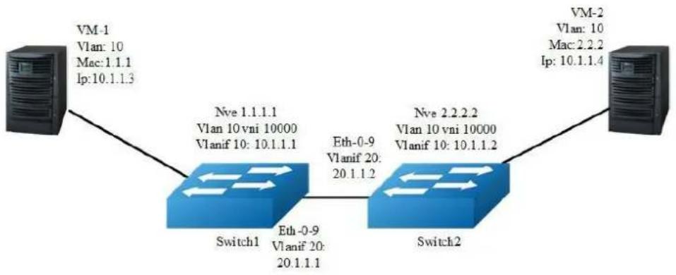
flowchart
graph TD
A["VM-1\nVlan: 10\nMac: 1.1.1\nIp: 10.1.1.3"] --> B["Switch1\nNve 1.1.1.1\nVlan 10 vni 10000\nVlanif 10: 10.1.1.1"]
B --> C["Switch2\nNve 2.2.2.2\nVlan 10 vni 10000\nVlanif 10: 10.1.1.2"]
C --> D["VM-2\nVlan: 10\nMac: 2.2.2\nIp: 10.1.1.4"]
B -->|Eth-0-9\nVlanif 20:\n20.1.1.1| C
Figure 17-3 EBGP_EVPN
In the following example, VM-1 & VM-2 are encapsulated in same vni to make up the distributed route via vxlan by EBGP EVPN for sending vxlan tunnel and host information;
The following configuration should be operated on all switches if the switch ID is not specified.
step 1 Enter the configure mode
Switch# configure terminal
step 2 Enter the vlan configure mode and create vlan, enable overlay for each vlan
Switch(config)# vlan database
Switch(config-vlan)# vlan 10, 20
Switch(config-vlan)# vlan 10 overlay enable
Switch(config-vlan)# exit
option: enable arp broadcast suppress for vlan
Switch(config-vlan)# vlan 10 arp-broadcast-suppress enable
step 3 Create vlan mapping vni for vxlan
Switch(config)# overlay
Switch(config-overlay)# vlan 10 vni 10000
Switch(config-vlan)# exit
option: Disable inner fdb learning for overlay
Switch(config-overlay)# vlan 10 mac-address-tunnel learning-disable
step 4 Create evpn instance
Switch(config)# evpn
Switch(config-evpn)# vni 10000
Switch(config-evi)# rd auto
Switch(config-evi)# route-target both 1:10000
Switch(config-evi)# exit
step 5 Create a vrf instance, and enable EVPN
Configuring Switch1:
Switch1(config)# ip vrf tenant
Switch1(config-vrf)# rd 1:20000
Switch1(config-vrf)# route-target both 1:10000 evpn
Switch1(config-vrf)# vxlan vni 20000
Switch1(config-vrf)# exit
Configuring Switch2:
Switch2(config)# ip vrf tenant
Switch2(config-vrf)# rd 2:20000
Switch2(config-vrf)# route-target both 1:10000 evpn
Switch2(config-vrf)# vxlan vni 20000
Switch2(config-vrf)# exit
step 6 Create the layer 3 interface, set the ip address and enable distributed gateway
Configuring Switch1:
Switch1(config)# interface vlan 10
Switch1(config-if)# ip vrf forwarding tenant
Switch1(config-if)# overlay distributed-gateway enable
Switch1(config-if)# overlay host-collect enable
Switch1(config-if)# ip address 10.1.1.1/24
Switch1(config-if)# exit
Switch1(config)# interface vlan 20
Switch1(config-if)# ip address 20.1.1.1/24
Switch1(config-if)# exit
Configuring Switch2:
Switch2(config)# interface vlan 10
Switch2(config-if)# ip vrf forwarding tenant
Switch2(config-if)# overlay distributed-gateway enable
Switch2(config-if)# overlay host-collect enable
Switch2(config-if)# ip address 10.1.1.2/24
Switch2(config-if)# exit
Switch2(config)# interface vlan 20
Switch2(config-if)# ip address 20.1.1.2/24
Switch2(config-if)# exit
step 7 Enter the interface configure mode and set the attributes of the interface
Switch(config)# interface eth-0-1
Switch(config-if)# switchport access vlan 10
Switch(config-if)# no shutdown
Switch(config-if)# exit
Switch(config)# interface eth-0-9
Switch(config-if)# switchport mode trunk
Switch(config-if)# switchport trunk allowed vlan add 20
Switch(config-if)# vxlan uplink enable
Switch(config-if)# no shutdown
Switch(config-if)# exit
Step 8 Create NVE
Configuring Switch1:
Switch1(config)# interface loopback 1
Switch1(config-if)# ip address 1.1.1.1/32
Switch1(config-if)# exit
Switch1(config)# interface nve 1
Switch1(config-if)# source loopback 1
Switch1(config-if)# member vni 10000
Switch1(config-if)# member vni 20000 associate-vrf
Switch1(config-if)# exit
Configuring Switch2:
Switch2(config)# interface loopback 1
Switch2(config-if)# ip address 2.2.2.2/32
Switch2(config-if)# exit
Switch2(config)# interface nve 1
Switch2(config-if)# source loopback 1
Switch2(config-if)# member vni 10000
Switch2(config-if)# member vni 20000 associate-vrf
Switch2(config-if)# exit
option: configure the attribute of EVPN tunnel
Switch(config-if)# keep-vlan-tag enable
Switch(config-if)# split-horizon disable
Switch(config-if)# encapsulation-dscp-strategy custom-assign 63
Switch(config-if)# virtual-mac a.a.a
Step 9 Create BGP EVPN
Configuring Switch1:
Switch1(config)# router bgp 100
Switch1(config-router)# neighbor 20.1.1.2 remote-as 200
Switch1(config-router)# address-family 12vpn evpn
Switch1(config-router-af)# neighbor 20.1.1.2 activate
Switch1(config-router-af)# neighbor 20.1.1.2 send-community extended
Switch1(config-router-af)# neighbor 20.1.1.2 attribute-unchanged next-hop
Switch1(config-router-af)# exit
Switch1(config-router)# exit
Configuring Switch2:
Switch2(config)# router bgp 200
Switch2(config-router)# neighbor 20.1.1.1 remote-as 100
Switch2(config-router)# address-family 12vpn evpn
Switch2(config-router-af)# neighbor 20.1.1.1 activate
Switch2(config-router-af)# neighbor 20.1.1.1 send-community extended
Switch2(config-router-af)# neighbor 20.1.1.1 attribute-unchanged next-hop
Switch2(config-router-af)# exit
Switch2(config-router)# exit
step 10 Create a static routes
Configuring Switch1:
Switch1(config)# ip route 2.2.2.2/32 20.1.1.2
Configuring Switch2:
Display the result on Switch1:
Switch1# show bgp evpn all
Status codes: s suppressed, d damped, h history, * valid, > best, i - internal,
S Stale
Origin codes: i - IGP, e - EGP, ? - incomplete
Network Next Hop Metric LocPrf Weight Path
Route Distinguisher: 1:10000 (L2VNI 10000)
*> [2]:[0]:[48]:[4623.28ef.da00]:[32]:[0.0.0.0]/136
1.1.1.1 32768 i
*> [2]:[0]:[48]:[4623.28ef.da00]:[32]:[10.1.1.3]/136
1.1.1.1 32768 i
*> [2]:[0]:[48]:[ac7f.lcc5.fe00]:[32]:[0.0.0.0]/136
2.2.2.2 0 200 i
*> [2]:[0]:[48]:[ac7f.lcc5.fe00]:[32]:[10.1.1.4]/136
2.2.2.2 0 200 i
*> [3]:[0]:[32]:[1.1.1.1]/80
1.1.1.1 32768 i
*> [3]:[0]:[32]:[10.20.30.40]/80
2.2.2.2 0 200 i
Route Distinguisher: 1:10000
*> [2]:[0]:[48]:[ac7f.lcc5.fe00]:[32]:[0.0.0.0]/136
2.2.2.2 0 200 i
*> [2]:[0]:[48]:[ac7f.lcc5.fe00]:[32]:[10.1.1.4]/136
2.2.2.2 0 200 i
*> [3]:[0]:[32]:[2.2.2.2]/80
2.2.2.2 0 200 i
Route Distinguisher: 1:20000 (L3VNI 20000)
*> [2]:[0]:[48]:[ac7f.lcc5.fe00]:[32]:[10.1.1.4]/136
2.2.2.2
Switch1# show overlay tunnel
Vlan Vni Type Remote-vtep IP-Address Src-Address Head-end-flooding Protocol 10 10000 VxLAN 0 2.2.2.2 1.1.1.1 Enable Evpn
Display the result on Switch2:
Head-end-floodingSwitch2# show bgp evpn all
Status codes: s suppressed, d damped, h history, * valid, > best, i - internal,
S Stale
Origin codes: i - IGP, e - EGP, ? - incomplete
Network Next Hop Metric LocPrf Weight Path
Route Distinguisher: 1:10000 (L2VNI 10000)
*> [2]:[0]:[48]:[4623.28ef.da00]:[32]:[0.0.0.0]/136
1.1.1.1 0 100 i
*> [2]:[0]:[48]:[4623.28ef.da00]:[32]:[10.1.1.3]/136
1.1.1.1 0 100 i
*> [2]:[0]:[48]:[ac7f.1cc5.fe00]:[32]:[0.0.0.0]/136
2.2.2.2 32768 i
*> [2]:[0]:[48]:[ac7f.1cc5.fe00]:[32]:[10.1.1.4]/136
2.2.2.2 32768 i
*> [3]:[0]:[32]:[1.1.1.1]/80
1.1.1.1 0 100 i
*> [3]:[0]:[32]:[2.2.2.2]/80
2.2.2.2 32768 i
Route Distinguisher: 1:10000
*> [2]:[0]:[48]:[4623.28ef.da00]:[32]:[0.0.0.0]/136
1.1.1.1 0 100 i
*> [2]:[0]:[48]:[4623.28ef.da00]:[32]:[10.1.1.3]/136
1.1.1.1 0 100 i
*> [3]:[0]:[32]:[1.1.1.1]/80
1.1.1.1 0 100 i
Route Distinguisher: 2:20000 (L3VNI 20000)
*> [2]:[0]:[48]:[4623.28ef.da00]:[32]:[10.1.1.3]/136
1.1.1.1 0 100 i
Switch2# show overlay tunnel
Vlan Vni Type Remote-vtep IP-Address Src-Address Head-end-flooding Protocol 10 10000 VxLAN 0 1.1.1.1 2.2.2.2 Enable Evpn
Configuring VXLAN Distributed Routing by IBGP EVPN
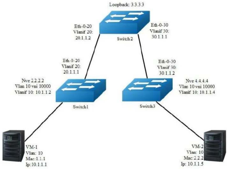
flowchart
graph TD
A["Loopback: 3.3.3.3"] --> B["Switch1"]
A --> C["Switch2"]
A --> D["Switch3"]
B --> E["VM-1\nVlan: 10\nMac:1.1.1\nIp:10.1.1.1"]
C --> F["Eth-0-20\nVlanif 20:\n20.1.1.2"]
C --> G["Eth-0-30\nVlanif 30:\n30.1.1.1"]
D --> H["Nve 2.2.2.2\nVlan 10 vni 10000\nVlanif 10: 10.1.1.2"]
D --> I["Eth-0-20\nVlanif 20:\n20.1.1.1"]
D --> J["Eth-0-30\nVlanif 30:\n30.1.1.2"]
D --> K["Nve 4.4.4.4\nVlan 10 vni 10000\nVlanif 10: 10.1.1.4"]
D --> L["VM-2\nVlan: 10\nMac: 2.2.2\nIp: 10.1.1.5"]
Figure 17-4 IBGP_EVPN
In the following example, VM-1 & VM-2 are encapsulated in same vni to make up the distributed route via vxlan by IBGP EVPN for sending vxlan tunnel and host information;EVPN route is exchanged by bgp route reflector.
The following configuration should be operated on all switches if the switch ID is not specified.
step 1 Enter the configure mode
Switch# configure terminal
step 2 Enter the vlan configure mode and create vlan, enable overlay for each vlan
Configuring Switch1:
Switch1(config)# vlan database
Switch1(config-vlan)# vlan 10, 20
Switch1(config-vlan)# vlan 10 overlay enable
Switch1(config-vlan)# exit
Configuring Switch2:
Switch2(config)# vlan database
Switch2(config-vlan)# vlan 20, 30
Switch2(config-vlan)# exit
Configuring Switch3:
Switch3(config)# vlan database
Switch3(config-vlan)# vlan 10, 30
Switch3(config-vlan)# vlan 10 overlay enable
Switch3(config-vlan)# exit
option: enable arp broadcast suppress for vlan
Switch(config-vlan)# vlan 10 arp-broadcast-suppress enable
step 3 Create vlan mapping vni for vxlan
Configuring Switch1:
Switch1(config)# overlay
Switch1(config-overlay)# vlan 10 vni 10000
Switch1(config-vlan)# exit
option: Disable inner fdb learning for overlay
Switch1(config-overlay)# vlan 10 mac-address-tunnel learning-disable
Configuring Switch3:
Switch3(config)# overlay
Switch3(config-overlay)# vlan 10 vni 10000
Switch3(config-vlan)# exit
option: Disable inner fdb learning for overlay
Switch3(config-overlay)# vlan 10 mac-address-tunnel learning-disable
step 4 Create evpn instance
Configuring Switch1:
Switch1(config)# evpn
Switch1(config-evpn)# vni 10000
Switch1(config-evi)# rd 2:2
Switch1(config-evi)# route-target both 20:20
Switch1(config-evi)# exit
Configuring Switch2:
Switch2(config)# evpn
Configuring Switch3:
Switch3(config)# evpn
Switch3(config-evpn)# vni 10000
Switch3(config-evi)# rd 4:4
Switch3(config-evi)# route-target both 20:20
Switch3(config-evi)# exit
step 5 Create a vrf instance, and enable EVPN
Configuring Switch1:
Switch1(config)# ip vrf tenant
Switch1(config-vrf)# rd 22:22
Switch1(config-vrf)# route-target both 20:20 evpn
Switch1(config-vrf)# vxlan vni 20000
Switch1(config-vrf)# exit
在 switch3 配置:
Configuring Switch3:
Switch3(config)# ip vrf tenant
Switch3(config-vrf)# rd 44:44
Switch3(config-vrf)# route-target both 20:20 evpn
Switch3(config-vrf)# vxlan vni 20000
Switch3(config-vrf)# exit
step 6 Create the layer 3 interface, set the ip address and enable distributed gateway
Configuring Switch1:
Switch1(config)# interface vlan 10
Switch1(config-if)# ip vrf forwarding tenant
Switch1(config-if)# overlay distributed-gateway enable
Switch1(config-if)# overlay host-collect enable
Switch1(config-if)# ip address 10.1.1.2/24
Switch1(config-if)# exit
Switch1(config)# interface vlan 20
Switch1(config-if)# ip address 20.1.1.1/24
Switch1(config-if)# exit
Configuring Switch2:
Switch2(config)# interface vlan 20
Switch2(config-if)# ip address 20.1.1.2/24
Switch2(config-if)# exit
Switch2(config)# interface vlan 30
Switch2(config-if)# ip address 30.1.1.1/24
Switch2(config-if)# exit
Configuring Switch3:
Switch3(config)# interface vlan 10
Switch3(config-if)# ip vrf forwarding tenant
Switch3(config-if)# overlay distributed-gateway enable
Switch3(config-if)# overlay host-collect enable
Switch3(config-if)# ip address 10.1.1.3/24
Switch3(config-if)# exit
Switch3(config)# interface vlan 30
Switch3(config-if)# ip address 30.1.1.2/24
Switch3(config-if)# exit
step 7 Enter the interface configure mode and set the attributes of the interface
Configuring Switch1:
Switch1(config)# interface eth-0-10
Switch1(config-if)# switchport access vlan 10
Switch1(config-if)# no shutdown
Switch1(config-if)# exit
Switch1(config)# interface eth-0-20
Switch1(config-if)# switchport mode trunk
Switch1(config-if)# switchport trunk allowed vlan add 20
Switch1(config-if)# vxlan uplink enable
Switch1(config-if)# no shutdown
Switch1(config-if)# exit
Configuring Switch2:
Switch2(config)# interface eth-0-20
Switch2(config-if)# switchport mode trunk
Switch2(config-if)# switchport trunk allowed vlan add 20
Switch2(config-if)# vxlan uplink enable
Switch2(config-if)# no shutdown
Switch2(config-if)# exit
Switch2(config)# interface eth-0-30
Switch2(config-if)# switchport mode trunk
Switch2(config-if)# switchport trunk allowed vlan add 30
Switch2(config-if)# vxlan uplink enable
Switch2(config-if)# no shutdown
Switch2(config-if)# exit
Configuring Switch3:
Switch3(config)# interface eth-0-10
Switch3(config-if)# switchport access vlan 10
Switch3(config-if)# no shutdown
Switch3(config-if)# exit
Switch3(config)# interface eth-0-30
Switch3(config-if)# switchport mode trunk
Switch3(config-if)# switchport trunk allowed vlan add 30
Switch3(config-if)# vxlan uplink enable
Switch3(config-if)# no shutdown
Switch3(config-if)# exit
Step 8 Create NVE
Configuring Switch1:
Switch1(config)# interface loopback 2
Switch1(config-if)# ip address 2.2.2.2/32
Switch1(config-if)# exit
Switch1(config)# interface nve 1
Switch1(config-if)# source 2.2.2.2
Switch1(config-if)# member vni 10000
Switch1(config-if)# member vni 20000 associate-vrf
Switch1(config-if)# exit
Configuring Switch2:
Switch2(config)# interface loopback 3
Switch2(config-if)# ip address 3.3.3.3/32
Switch2(config-if)# exit
Configuring Switch3:
Switch3(config)# interface loopback 4
Switch3(config-if)# ip address 4.4.4.4/32
Switch3(config-if)# exit
Switch3(config)# interface nve 1
Switch3(config-if)# source 4.4.4.4
Switch3(config-if)# member vni 10000
Switch3(config-if)# member vni 20000 associate-vrf
Switch3(config-if)# exit
option: configure the attribute of EVPN tunnel
Switch(config-if)# keep-vlan-tag enable
Switch(config-if)# split-horizon disable
Switch(config-if)# encapsulation-dscp-strategy custom-assign 63
Switch(config-if)# virtual-mac a.a.a
Step 9 Create BGP EVPN
Configuring Switch1:
Switch1(config)# router bgp 100
Switch1(config-router)# neighbor 3.3.3.3 remote-as 100
Switch1(config-router)# neighbor 3.3.3.3 update-source loopback2
Switch1(config-router)# neighbor 20.1.1.2 remote-as 100
Switch1(config-router)# address-family ipv4
Switch1(config-router-af)# network 2.2.2.2 mask 255.255.255.255
Switch1(config-router-af)# neighbor 20.1.1.2 weight 32768
Switch1(config-router-af)# exit
Switch1(config-router)# address-family l2vpn evpn
Switch1(config-router-af)# neighbor 3.3.3.3 activate
Switch1(config-router-af)# neighbor 3.3.3.3 send-community extended
Switch1(config-router-af)# exit
Switch1(config-router)# exit
Configuring Switch2:
Switch2(config)# router bgp 100
Switch2(config-router)# neighbor 2.2.2.2 remote-as 100
Switch2(config-router)# neighbor 2.2.2.2 update-source loopback3
Switch2(config-router)# neighbor 4.4.4.4 remote-as 100
Switch2(config-router)# neighbor 4.4.4.4 update-source loopback3
Switch2(config-router)# neighbor 20.1.1.1 remote-as 100
Switch2(config-router)# neighbor 30.1.1.2 remote-as 100
Switch2(config-router)# address-family ipv4
Switch2(config-router-af)# network 3.3.3.3 mask 255.255.255.255
Switch2(config-router-af)# network 20.1.1.0 mask 255.255.255.0
Switch2(config-router-af)# network 30.1.1.0 mask 255.255.255.0
Switch2(config-router-af)# neighbor 20.1.1.1 weight 32768
Switch2(config-router-af)# neighbor 20.1.1.1 route-reflector-client
Switch2(config-router-af)# neighbor 20.1.1.1 next-hop-self
Switch2(config-router-af)# neighbor 30.1.1.2 weight 32768
Switch2(config-router-af)# neighbor 30.1.1.2 route-reflector-client
Switch2(config-router-af)# neighbor 30.1.1.2 next-hop-self
Switch2(config-router-af)# exit
Switch2(config-router)# address-family l2vpn evpn
Switch2(config-router-af)# neighbor 2.2.2.2 activate
Switch2(config-router-af)# neighbor 2.2.2.2 route-reflector-client
Switch2(config-router-af)# neighbor 2.2.2.2 send-community extended
Switch2(config-router-af)# neighbor 4.4.4.4 activate
Switch2(config-router-af)# neighbor 4.4.4.4 route-reflector-client
Switch2(config-router-af)# neighbor 4.4.4.4 send-community extended
Switch2(config-router-af)# exit
Switch2(config-router)# exit
Configuring Switch3:
Switch3(config)# router bgp 100
Switch3(config-router)# neighbor 3.3.3.3 remote-as 100
Switch3(config-router)# neighbor 3.3.3.3 update-source loopback4
Switch3(config-router)# neighbor 30.1.1.1 remote-as 100
Switch3(config-router)# address-family ipv4
Switch3(config-router-af)# network 4.4.4.4 mask 255.255.255.255
Switch3(config-router-af)# neighbor 30.1.1.1 weight 32768
Switch3(config-router-af)# exit
Switch3(config-router)# address-family 12vpn evpn
Switch3(config-router-af)# neighbor 3.3.3.3 activate
Switch3(config-router-af)# neighbor 3.3.3.3 send-community extended
Switch3(config-router-af)# exit
Switch3(config-router)# exit
step 10 Exit the configure mode
Switch(config)# end
step 11 Validation
Display the result on Switch1:
Switch1# show bgp evpn all
Status codes: s suppressed, d damped, h history, * valid, > best, i - internal,
S Stale
Origin codes: i - IGP, e - EGP, ? - incomplete
Network Next Hop Metric LocPrf Weight Path
Route Distinguisher: 2:2 (L2VNI 10000)
*> [2]:[0]:[48]:[988b.123a.4000]:[32]:[0.0.0.0]/136
2.2.2.2 32768 i
*> [2]:[0]:[48]:[988b.123a.4000]:[32]:[10.1.1.1]/136
2.2.2.2 32768 i
*> [3]:[0]:[32]:[2.2.2.2]/80
2.2.2.2 32768 i
*>i[3]:[0]:[32]:[4.4.4.4]/80
4.4.4.4 100 0 i
Route Distinguisher: 4:4
*>i[3]:[0]:[32]:[4.4.4.4]/80
4.4.4.4 100 0 i
Switch1# show overlay tunnel
Vlan Vni Type Remote-vtep IP-Address Src-Address Head-end-flooding Protocol 10 10000 VxLAN 0 4.4.4.4 2.2.2.2 Enable Evpn
Display the result on Switch2:
Switch2# show bgp evpn all
Status codes: s suppressed, d damped, h history, * valid, > best, i - internal,
S Stale
Origin codes: i - IGP, e - EGP, ? - incomplete
Network Next Hop Metric LocPrf Weight Path
Route Distinguisher: 2:2
*>i[2]:[0]:[48]:[988b.123a.4000]:[32]:[0.0.0.0]/136
2.2.2.2 100 0 i
*>i[2]:[0]:[48]:[988b.123a.4000]:[32]:[10.1.1.1]/136
2.2.2.2 100 0 i
*>i[3]:[0]:[32]:[2.2.2.2]/80
2.2.2.2 100 0 i
Route Distinguisher: 4:4
*>i[3]:[0]:[32]:[4.4.4.4]/80
4.4.4.4 100 0 i
Display the result on Switch3:
Switch3# show bgp evpn all
Status codes: s suppressed, d damped, h history, * valid, > best, i - internal,
S Stale
Origin codes: i - IGP, e - EGP, ? - incomplete
Network Next Hop Metric LocPrf Weight Path
Route Distinguisher: 2:2
*>i[2]:[0]:[48]:[988b.123a.4000]:[32]:[0.0.0.0]/136
2.2.2.2 100 0 i
*>i[2]:[0]:[48]:[988b.123a.4000]:[32]:[10.1.1.1]/136
2.2.2.2 100 0 i
*>i[3]:[0]:[32]:[2.2.2.2]/80
2.2.2.2 100 0 i
Route Distinguisher: 4:4 (L2VNI 10000)
*>i[2]:[0]:[48]:[988b.123a.4000]:[32]:[0.0.0.0]/136
2.2.2.2 100 0 i
*>i[2]:[0]:[48]:[988b.123a.4000]:[32]:[10.1.1.1]/136
2.2.2.2 100 0 i
*>i[3]:[0]:[32]:[2.2.2.2]/80
2.2.2.2 100 0 i
*> [3]:[0]:[32]:[4.4.4.4]/80
4.4.4.4 32768 i
Route Distinguisher: 44:44 (L3VNI 20000)
*>i[2]: [0]: [48]: [988b.123a.4000]: [32]: [10.1.1.1]/136
2.2.2.2 100 0 i
Switch3# show overlay tunnel
Vlan Vni Type Remote-vtep IP-Address Src-Address Head-end-flooding Protocol 10 10000 VxLAN 0 2.2.2.2 4.4.4.4 Enable Evpn
Switch3# show mac address-table Mac Address Table
(*) - Security Entry (M) - MLAG Entry
(MO) - MLAG Output Entry (MI) - MLAG Input Entry
Vlan Mac Address Type Ports
30 fcc0.9318.0a00 dynamic eth-0-9
10 988b.123a.4000 dynamic VxLAN: 4.4.4.4->2.2.2.2(EI)
Switch3# show ip route vrf tenant
Codes: K - kernel, C - connected, S - static, R - RIP, B - BGP
O - OSPF, IA - OSPF inter area
N1 - OSPF NSSA external type 1, N2 - OSPF NSSA external type 2
E1 - OSPF external type 1, E2 - OSPF external type 2
i - IS-IS, L1 - IS-IS level-1, L2 - IS-IS level-2, ia - IS-IS inter area
Dc - DHCP Client
[*] - [AD/Metric]
* - candidate default
C 10.1.1.0/24 is directly connected, vlan10
C 10.1.1.3/32 is in local loopback, vlan10
B 10.1.1.1/32 is in overlay remote vxlan vstep:4.4.4.4->2.2.2.2, vni:20000
17.2 Configuring NVGRE
17.2.1 Overview
Function Introduction
Network Virtualization using Generic Routing Encapsulation (NVGRE) is an encapsulation technique intended to allow virtual network overlays across the physical network. NVGRE uses Generic Routing Encapsulation (GRE) as the encapsulation method. It uses the lower 24 bits of the GRE header to represent the Tenant Network Identifier (TNI.) Like VXLAN this 24 bit space allows for 16 million virtual networks.
Principle Description
N/A
17.2.2 Configuration
NVGRE Configuration
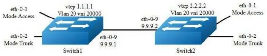
flowchart
graph LR
subgraph Switch1
A["eth-0-1 Mode Access"] --> B["vtep 1.1.1.1 Vlan 20 vni 20000"]
C["eth-0-2 Mode Trunk"] --> D["Switch1"]
E["eth-0-9"] --> F["Switch2"]
G["eth-0-9"] --> H["Switch2"]
end
subgraph Switch2
I["eth-0-1 Mode Access"] --> J["vtep 2.2.2.2 Vlan 20 vni 20000"]
K["eth-0-2 Mode Trunk"] --> L["Switch2"]
M["eth-0-9"] --> N["Switch2"]
O["eth-0-9"] --> P["Switch2"]
end
Figure 17-5 NVGRE
In the following example, switch1 and switch2 are connected via layer 3 route. The traffic of vlan 20 are encapsulated in vni 20000, in order to pass through the layer 3 networks.
The following configuration should be operated on all switches if the switch ID is not specified.
step 1 Enter the configure mode
Switch# configure terminal
step 2 Enter the vlan configure mode and create vlan, enable overlay for each vlan
Switch(config)# vlan database
Switch(config-vlan)# vlan 20
Switch(config-vlan)# vlan 20 overlay enable
Switch(config-vlan)# exit
step 3 Enter the interface configure mode and set the attributes of the interface
Switch(config)# interface eth-0-1
Switch(config-if)# switchport access vlan 20
Switch(config-if)# no shutdown
Switch(config-if)# exit
Switch(config)# interface eth-0-2
Switch(config-if)# switchport mode trunk
Switch(config-if)# switchport trunk allowed vlan add 20
Switch(config-if)# no shutdown
Switch(config-if)# exit
Interface configuration for Switch1:
Switch(config)# interface eth-0-9
Switch(config-if)# no switchport
Switch(config-if)# ip address 9.9.9.1/24
Switch(config-if)# overlay uplink enable
Switch(config-if)# no shutdown
Switch(config-if)# exit
Switch(config)# interface loopback0
Switch(config-if)# ip address 1.1.1.1/32
Switch(config-if)# exit
Interface configuration for Switch2:
Switch(config)# interface eth-0-9
Switch(config-if)# no switchport
Switch(config-if)# ip address 9.9.9.2/24
Switch(config-if)# overlay uplink enable
Switch(config-if)# no shutdown
Switch(config-if)# exit
Switch(config)# interface loopback0
Switch(config-if)# ip address 2.2.2.2/32
Switch(config-if)# exit
Step 4 Create a static route
Configuring Switch1:
Switch(config)# ip route 2.2.2.0/24 9.9.9.2
Configuring Switch2:
Switch(config)# ip route 1.1.1.0/24 9.9.9.1
step 5 Set attributes for overlay
Configuring Switch1:
Switch(config)# overlay
Switch(config-overlay)# source 1.1.1.1
Switch(config-overlay)# remote-vtep 1 ip-address 2.2.2.2 type nvgre
Switch(config-overlay)# vlan 20 vni 20000
Switch(config-overlay)# vlan 20 remote-vtep 1
Switch(config-overlay)# exit
Configuring Switch2:
Switch(config)# overlay
Switch(config-overlay)# source 2.2.2.2
Switch(config-overlay)# remote-vtep 1 ip-address 1.1.1.1 type nvgre
Switch(config-overlay)# vlan 20 vni 20000
Switch(config-overlay)# vlan 20 remote-vtep 1
Switch(config-overlay)# exit
step 6 Exit the configure mode
Switch(config)# end
step 7 Validation
Display the result on Switch1:
Switch# show overlay vlan 20
ECMP Mode : Normal
Source VTEP : 1.1.1.1
VLAN ID : 20
VNI : 20000
EVPN Tunnel Data-fdb Learning : Enable
Remote VTEP NUM: 1
Index: 1, Ip address: 2.2.2.2, Source ip: 1.1.1.1, Type: NvGRE, Protocol:
Static
DVR Gateway NUM: 0
Display the result on Switch2:
Switch# show overlay vlan 20
ECMP Mode : Normal
Source VTEP : 2.2.2.2
VLAN ID : 20
VNI : 20000
EVPN Tunnel Data-fdb Learning : Enable
Remote VTEP NUM: 1
Index: 1, Ip address: 1.1.1.1, Source ip: 2.2.2.2, Type: NvGRE, Protocol:
Static
DVR Gateway NUM: 0
Configuring NVGRE Routing
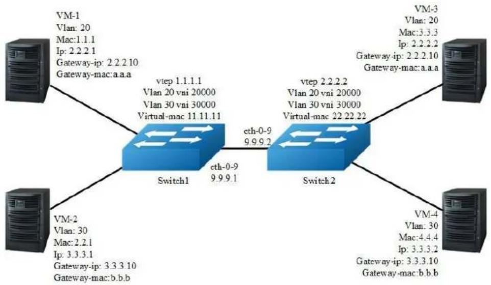
flowchart
graph TD
VM1["VM-1\nVlan: 20\nMac:1.1.1\nIp: 2.2.2.1\nGateway-ip: 2.2.2.10\nGateway-mac:a.a.a"] --> Switch1["Switch1"]
Switch1 -->|vtep 1.1.1.1\nVlan 20 vni 20000\nVlan 30 vni 30000\nVirtual-mac 11.11.11] --> Switch2["Switch2"]
Switch2 -->|vtep 2.2.2.2\nVlan 20 vni 20000\nVlan 30 vni 30000\nVirtual-mac 22.22.22] --> Switch1
Switch1 -->|cth-0-9\n9.9.9.1| Switch2
Switch2 -->|VM-4\nVlan: 30\nMac:4.4.4\nIp: 3.3.3.2\nGateway-ip: 3.3.3.10\nGateway-mac:b.b.b] --> Switch2
Switch1 -->|VM-2\nVlan: 30\nMac:2.2.1\nIp: 3.3.3.1\nGateway-ip: 3.3.3.10\nGateway-mac:b.b.b] --> Switch2
Switch2 -->|VM-3\nVlan: 20\nMac:3.3.3\nIp: 2.2.2.2\nGateway-ip: 2.2.2.10\nGateway-mac:a.a.a] --> Switch1
Figure 17-6 NVGRE
In the following example, VM-1 & VM-3 are encapsulated in same vni to make up the distributed route via NVGRE; VM-2 & VM-4 are encapsulated in another vni to make up the distributed route via NVGRE.
The following configuration should be operated on all switches if the switch ID is not specified.
step 1 Enter the configure mode
Switch# configure terminal
step 2 Enter the vlan configure mode and create vlan, enable overlay for each vlan
Switch(config)# vlan database
Switch(config-vlan)# vlan 20,30
Switch(config-vlan)# vlan 20 overlay enable
Switch(config-vlan)# vlan 30 overlay enable
Switch(config-vlan)# exit
step 3 Create a vrf instance
step 4 Create the layer 3 interface and set the ip address
Configuring Switch1:
Switch(config)# interface vlan 20
Switch(config-if)# ip vrf forwarding tenant
Switch(config-if)# ip address 2.2.2.111/24
Switch(config-if)# exit
Switch(config)# interface vlan 30
Switch(config-if)# ip vrf forwarding tenant
Switch(config-if)# ip address 3.3.3.111/24
Switch(config-if)# exit
Configuring Switch2:
Switch(config)# interface vlan 20
Switch(config-if)# ip vrf forwarding tenant
Switch(config-if)# ip address 2.2.2.222/24
Switch(config-if)# exit
Switch(config)# interface vlan 30
Switch(config-if)# ip vrf forwarding tenant
Switch(config-if)# ip address 3.3.3.222/24
Switch(config-if)# exit
step 5 Enter the interface configure mode and set the attributes of the interface
Switch(config)# interface eth-0-1
Switch(config-if)# switchport mode trunk
Switch(config-if)# switchport trunk allowed vlan add 20
Switch(config-if)# no shutdown
Switch(config-if)# exit
Switch(config)# interface eth-0-2
Switch(config-if)# switchport mode trunk
Switch(config-if)# switchport trunk allowed vlan add 30
Switch(config-if)# no shutdown
Switch(config-if)# exit
Configuring Switch1:
Switch(config)# interface eth-0-9
Switch(config-if)# no switchport
Switch(config-if)# ip address 9.9.9.1/24
Switch(config-if)# overlay uplink enable
Switch(config-if)# no shutdown
Switch(config-if)# exit
Switch(config)# interface loopback0
Switch(config-if)# ip address 1.1.1.1/32
Switch(config-if)# exit
Configuring Switch2:
Switch(config)# interface eth-0-9
Switch(config-if)# no switchport
Switch(config-if)# ip address 9.9.9.2/24
Switch(config-if)# overlay uplink enable
Switch(config-if)# no shutdown
Switch(config-if)# exit
Switch(config)# interface loopback0
Switch(config-if)# ip address 2.2.2.2/32
Switch(config-if)# exit
step 6 Set attributes for overlay
Configuring Switch1:
Switch(config)# overlay
Switch(config-overlay)# source 1.1.1.1
Switch(config-overlay)# remote-vtep 1 ip-address 2.2.2.2 type nvgre
Switch(config-overlay)# remote-vtep 1 virtual-mac 22.22.22
Switch(config-overlay)# vlan 20 vni 20000
Switch(config-overlay)# vlan 30 vni 30000
Switch(config-overlay)# vlan 20 remote-vtep 1
Switch(config-overlay)# vlan 30 remote-vtep 1
Switch(config-overlay)# vlan 20 gateway-mac a.a.a
Switch(config-overlay)# vlan 30 gateway-mac b.b.b
Switch(config-overlay)# exit
Configuring Switch2:
Switch(config)# overlay
Switch(config-overlay)# source 2.2.2.2
Switch(config-overlay)# remote-vtep 1 ip-address 1.1.1.1 type nvgre
Switch(config-overlay)# remote-vtep 1 virtual-mac 11.11.11
Switch(config-overlay)# vlan 20 vni 20000
Switch(config-overlay)# vlan 30 vni 30000
Switch(config-overlay)# vlan 20 remote-vtep 1
Switch(config-overlay)# vlan 30 remote-vtep 1
Switch(config-overlay)# vlan 20 gateway-mac a.a.a
Switch(config-overlay)# vlan 30 gateway-mac b.b.b
Switch(config-overlay)# exit
step 7 Create a static routes and NVGRE routes
Configuring Switch1:
Switch(config)# ip route 2.2.2.0/24 9.9.9.2
Switch(config)# ip route vrf tenant 2.2.2.2/32 remote-vtep 1 vni 20000 inner-macda 3.3.3
Switch(config)# ip route vrf tenant 3.3.3.2/32 remote-vtep 1 vni 30000
Configuring Switch2:
Switch(config)# ip route 1.1.1.0/24 9.9.9.1
Switch(config)# ip route vrf tenant 2.2.2.1/32 remote-vtep 1 vni 20000 inner-macda 1.1.1
Switch(config)# ip route vrf tenant 3.3.3.1/32 remote-vtep 1 vni 30000
step 8 Exit the configure mode
Switch(config)# end
step 9 Validation
Display the result on Switch1:
Switch# show ip route vrf tenant
Codes: K - kernel, C - connected, S - static, R - RIP, B - BGP
O - OSPF, IA - OSPF inter area
N1 - OSPF NSSA external type 1, N2 - OSPF NSSA external type 2
E1 - OSPF external type 1, E2 - OSPF external type 2
i - IS-IS, L1 - IS-IS level-1, L2 - IS-IS level-2, ia - IS-IS inter area
Dc - DHCP Client
[*] - [AD/Metric]
* - candidate default
S 2.2.2.2/32 is in overlay remote nvgre vtep:1.1.1.1->2.2.2.2, vni:20000
S 3.3.3.2/32 is in overlay remote nvgre vtep:1.1.1.1->2.2.2.2, vni:30000
Display the result on Switch2:
Switch# show ip route vrf tenant
Codes: K - kernel, C - connected, S - static, R - RIP, B - BGP
O - OSPF, IA - OSPF inter area
N1 - OSPF NSSA external type 1, N2 - OSPF NSSA external type 2
E1 - OSPF external type 1, E2 - OSPF external type 2
i - IS-IS, L1 - IS-IS level-1, L2 - IS-IS level-2, ia - IS-IS inter area
Dc - DHCP Client
[*] - [AD/Metric]
* - candidate default
S 2.2.2.1/32 is in overlay remote nvgre vstep:2.2.2.2->1.1.1.1, vni:20000
S 3.3.3.1/32 is in overlay remote nvgre vstep:2.2.2.2->1.1.1.1, vni:30000
17.2.3 Application cases
N/A
17.3 Configuring GENEVE
17.3.1 Overview
Function Introduction
Generic Network Virtualization Encapsulation (GENEVE) is a networking technology that encapsulates MAC-based Layer 2 Ethernet frames within Layer 3 UDP packets to aggregate and tunnel multiple layer 2 networks across a Layer 3 infrastructure. GENEVE scales up to 16 million logical networks and supports layer 2 adjacency across IP networks. Multicast transmission architecture is used for broadcast/multicast/unknown packets.
Principle Description
N/A
17.3.2 Configuration
GENEVE Configuration
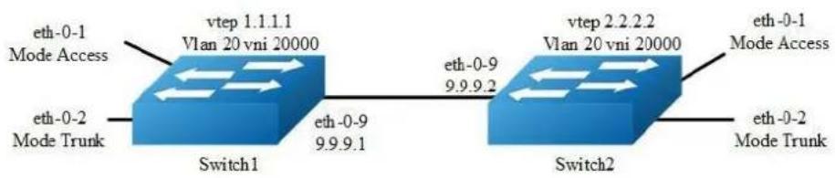
flowchart
graph LR
subgraph Switch1
A["eth-0-1 Mode Access"] --> B["vtep 1.1.1.1 Vlan 20 vni 20000"]
C["eth-0-2 Mode Trunk"] --> D["Switch1"]
E["eth-0-9 9.9.9.1"] --> F["Switch2"]
end
subgraph Switch2
G["vtep 2.2.2.2 Vlan 20 vni 20000"] --> H["eth-0-1 Mode Access"]
I["eth-0-2 Mode Trunk"] --> J["Switch2"]
end
Figure 17-7 GENEVE
In the following example, switch1 and switch2 are connected via layer 3 route. The traffic of vlan 20 are encapsulated in vni 20000, in order to pass through the layer 3 networks.
The following configuration should be operated on all switches if the switch ID is not specified.
step 1 Enter the configure mode
Switch# configure terminal
step 2 Enter the vlan configure mode and create vlan, enable overlay for each vlan
Switch(config)# vlan database
Switch(config-vlan)# vlan 20
Switch(config-vlan)# vlan 20 overlay enable
Switch(config-vlan)# exit
step 3 Enter the interface configure mode and set the attributes of the interface
Switch(config)# interface eth-0-1
Switch(config-if)# switchport access vlan 20
Switch(config-if)# no shutdown
Switch(config-if)# exit
Switch(config)# interface eth-0-2
Switch(config-if)# switchport mode trunk
Switch(config-if)# switchport trunk allowed vlan add 20
Switch(config-if)# no shutdown
Switch(config-if)# exit
Interface configuration for Switch1:
Switch(config)# interface eth-0-9
Switch(config-if)# no switchport
Switch(config-if)# ip address 9.9.9.1/24
Switch(config-if)# overlay uplink enable
Switch(config-if)# no shutdown
Switch(config-if)# exit
Switch(config)# interface loopback0
Switch(config-if)# ip address 1.1.1.1/32
Switch(config-if)# exit
Interface configuration for Switch2:
Switch(config)# interface eth-0-9
Switch(config-if)# no switchport
Switch(config-if)# ip address 9.9.9.2/24
Switch(config-if)# overlay uplink enable
Switch(config-if)# no shutdown
Switch(config-if)# exit
Switch(config)# interface loopback0
Switch(config-if)# ip address 2.2.2.2/32
Switch(config-if)# exit
Step 4 Create a static route
Configuring Switch1:
Switch(config)# ip route 2.2.2.0/24 9.9.9.2
Configuring Switch2:
Switch(config)# ip route 1.1.1.0/24 9.9.9.1
step 5 Set attributes for overlay
Configuring Switch1:
Switch(config)# overlay
Switch(config-overlay)# source 1.1.1.1
Switch(config-overlay)# remote-vtep 1 ip-address 2.2.2.2 type geneve
Switch(config-overlay)# vlan 20 vni 20000
Switch(config-overlay)# vlan 20 remote-vtep 1
Switch(config-overlay)# exit
Configuring Switch2:
Switch(config)# overlay
Switch(config-overlay)# source 2.2.2.2
Switch(config-overlay)# remote-vtep 1 ip-address 1.1.1.1 type geneve
Switch(config-overlay)# vlan 20 vni 20000
Switch(config-overlay)# vlan 20 remote-vtep 1
Switch(config-overlay)# exit
step 6 Exit the configure mode
Switch(config)# end
step 7 Validation
Display the result on Switch1:
Switch# show overlay vlan 20
ECMP Mode : Normal
Source VTEP : 1.1.1.1
VLAN ID : 20
VNI : 20000
EVPN Tunnel Data-fdb Learning : Eanble
Remote VTEP NUM: 1
Index: 1, Ip address: 2.2.2.2, Source ip: 1.1.1.1, Type: GENEVE, Protocol : Static
DVR Gateway NUM: 0
Display the result on Switch2:
Switch# show overlay vlan 20
ECMP Mode : Normal
Source VTEP : 2.2.2.2
VLAN ID : 20
VNI : 20000
EVPN Tunnel Data-fdb Learning : Enable
Remote VTEP NUM: 1
Index: 1, Ip address: 1.1.1.1, Source ip: 2.2.2.2, Type: GENEVE, Protocol : Static
DVR Gateway NUM: 0
Configuring GENEVE Routing
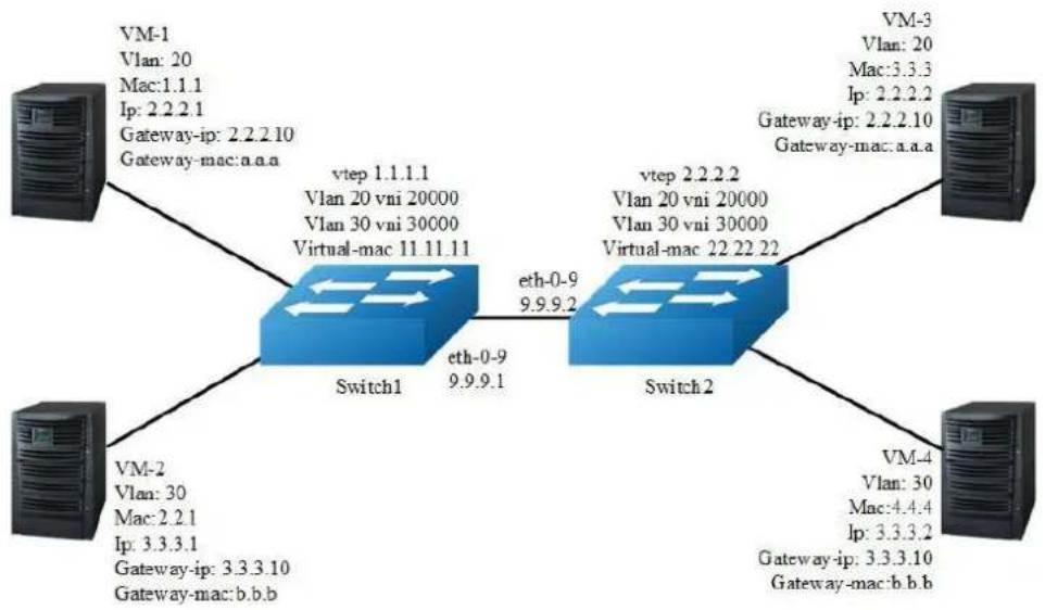
flowchart
graph TD
A["VM-1\nVlan: 20\nMac:1.1.1\nIp: 2.2.2.1\nGateway-ip: 2.2.2.10\nGateway-mac:a.a.a"] --> B["Switch1"]
C["VM-2\nVlan: 30\nMac:2.2.1\nIp: 3.3.3.1\nGateway-ip: 3.3.3.10\nGateway-mac:b.b.b"] --> B
D["VM-4\nVlan: 30\nMac:4.4.4\nIp: 3.3.3.2\nGateway-ip: 3.3.3.10\nGateway-mac:b.b.b"] --> E["Switch2"]
F["VM-3\nVlan: 20\nMac:3.3.3\nIp: 2.2.2.2\nGateway-ip: 2.2.2.10\nGateway-mac:a.a.a"] --> E
G["VM-1\nVlan: 20\nMac:1.1.1\nIp: 2.2.2.1\nGateway-ip: 2.2.2.10\nGateway-mac:a.a.a"] --> B
H["VM-3\nVlan: 20\nMac:3.3.3\nIp: 2.2.2.2\nGateway-ip: 2.2.2.10\nGateway-mac:a.a.a"] --> E
I["VM-4\nVlan: 30\nMac:4.4.4\nIp: 3.3.3.2\nGateway-ip: 3.3.3.10\nGateway-mac:b.b.b"] --> E
J["VM-1\nVlan: 20\nMac:1.1.1\nIp: 2.2.2.1\nGateway-ip: 2.2.2.10\nGateway-mac:a.a.a"] --> B
K["VM-3\nVlan: 20\nMac:3.3.3\nIp: 2.2.2.2\nGateway-ip: 2.2.2.10\nGateway-mac:a.a.a"] --> E
L["VM-1\nVlan: 20\nMac:1.1.1\nIp: 2.2.2.1\nGateway-ip: 2.2.2.10\nGateway-mac:a.a.a"] --> B
M["VM-3\nVlan: 20\nMac:3.3.3\nIp: 2.2.2.2\nGateway-ip: 2.2.2.10\nGateway-mac:a.a.a"] --> E
N["VM-4\nVlan: 30\nMac:4.4.4\nIp: 3.3.3.2\nGateway-ip: 3.3.3.10\nGateway-mac:b.b.b"] --> E
O["VM-1\nVlan: 20\nMac:1.1.1\nIp: 2.2.2.1\nGateway-ip: 2.2.2.10\nGateway-mac:a.a.a"] --> B
P["VM-3\nVlan: 20\nMac:3.3.3\nIp: 2.2.2.2\nGateway-ip: 2.2.2.10\nGateway-mac:a.a.a"] --> E
Q["VM-4\nVlan: 30\nMac:4.4.4\nIp: 3.3.3.2\nGateway-ip: 3.3.3.10\nGateway-mac:b.b.b"] --> E
R["VM-1\nVlan: 20\nMac:1.1.1\nIp: 2.2.2.1\nGateway-ip: 2.2.2.10\nGateway-mac:a.a.a"] --> B
S["VM-3\nVlan: 20\nMac:3.3.3\nIp: 2.2.2.2\nGateway-ip: 2.2.2.10\nGateway-mac:a.a.a"] --> E
T["VM-4\nVlan: 30\nMac:4.4.4\nIp: 3.3.3.2\nGateway-ip: 3.3.3.10\nGateway-mac:b.b.b"] --> E
U["VM-1\nVlan: 20\nMac:1.1.1\nIp: 2.2.2.1\nGateway-ip: 2.2.2.10\nGateway-mac:a.a.a"] --> B
V["VM-3\nVlan: 20\nMac:3.3.3\nIp: 2.2.2.2\nGateway-ip: 2.2.2.10\nGateway-mac:a.a.a"] --> E
Figure 17-8 GENEVE
In the following example, VM-1 & VM-3 are encapsulated in same vni to make up the distributed route via GENEVE; VM-2 & VM-4 are encapsulated in another vni to make up the distributed route via GENEVE.
The following configuration should be operated on all switches if the switch ID is not specified.
step 1 Enter the configure mode
Switch# configure terminal
step 2 Enter the vlan configure mode and create vlan, enable overlay for each vlan
Switch(config)# vlan database
Switch(config-vlan)# vlan 20,30
Switch(config-vlan)# vlan 20 overlay enable
Switch(config-vlan)# vlan 30 overlay enable
Switch(config-vlan)# exit
step 3 Create a vrf instance
step 4 Create the layer 3 interface and set the ip address
Configuring Switch1:
Switch(config)# interface vlan 20
Switch(config-if)# ip vrf forwarding tenant
Switch(config-if)# ip address 2.2.2.111/24
Switch(config-if)# exit
Switch(config)# interface vlan 30
Switch(config-if)# ip vrf forwarding tenant
Switch(config-if)# ip address 3.3.3.111/24
Switch(config-if)# exit
Configuring Switch2:
Switch(config)# interface vlan 20
Switch(config-if)# ip vrf forwarding tenant
Switch(config-if)# ip address 2.2.2.222/24
Switch(config-if)# exit
Switch(config)# interface vlan 30
Switch(config-if)# ip vrf forwarding tenant
Switch(config-if)# ip address 3.3.3.222/24
Switch(config-if)# exit
step 5 Enter the interface configure mode and set the attributes of the interface
Switch(config)# interface eth-0-1
Switch(config-if)# switchport mode trunk
Switch(config-if)# switchport trunk allowed vlan add 20
Switch(config-if)# no shutdown
Switch(config-if)# exit
Switch(config)# interface eth-0-2
Switch(config-if)# switchport mode trunk
Switch(config-if)# switchport trunk allowed vlan add 30
Switch(config-if)# no shutdown
Switch(config-if)# exit
Configuring Switch1:
Switch(config)# interface eth-0-9
Switch(config-if)# no switchport
Switch(config-if)# ip address 9.9.9.1/24
Switch(config-if)# overlay uplink enable
Switch(config-if)# no shutdown
Switch(config-if)# exit
Switch(config)# interface loopback0
Switch(config-if)# ip address 1.1.1.1/32
Switch(config-if)# exit
Configuring Switch2:
Switch(config)# interface eth-0-9
Switch(config-if)# no switchport
Switch(config-if)# ip address 9.9.9.2/24
Switch(config-if)# overlay uplink enable
Switch(config-if)# no shutdown
Switch(config-if)# exit
Switch(config)# interface loopback0
Switch(config-if)# ip address 2.2.2.2/32
Switch(config-if)# exit
step 6 Set attributes for overlay
Configuring Switch1:
Switch(config)# overlay
Switch(config-overlay)# source 1.1.1.1
Switch(config-overlay)# remote-vtep 1 ip-address 2.2.2.2 type geneve
Switch(config-overlay)# remote-vtep 1 virtual-mac 22.22.22
Switch(config-overlay)# vlan 20 vni 20000
Switch(config-overlay)# vlan 30 vni 30000
Switch(config-overlay)# vlan 20 remote-vtep 1
Switch(config-overlay)# vlan 30 remote-vtep 1
Switch(config-overlay)# vlan 20 gateway-mac a.a.a
Switch(config-overlay)# vlan 30 gateway-mac b.b.b
Switch(config-overlay)# exit
Configuring Switch2:
Switch(config)# overlay
Switch(config-overlay)# source 2.2.2.2
Switch(config-overlay)# remote-vtep 1 ip-address 1.1.1.1 type geneve
Switch(config-overlay)# remote-vtep 1 virtual-mac 11.11.11
Switch(config-overlay)# vlan 20 vni 20000
Switch(config-overlay)# vlan 30 vni 30000
Switch(config-overlay)# vlan 20 remote-vtep 1
Switch(config-overlay)# vlan 20 remote-vstep 1
Switch(config-overlay)# vlan 20 gateway-mac a.a.a
Switch(config-overlay)# vlan 30 gateway-mac b.b.b
Switch(config-overlay)# exit
step 7 Create a static routes and GENEVE routes
Configuring Switch1:
Switch(config)# ip route 2.2.2.0/24 9.9.9.2
Switch(config)# ip route vrf tenant 2.2.2.2/32 remote-vtep 1 vni 20000 inner-macda 3.3.3
Switch(config)# ip route vrf tenant 3.3.3.2/32 remote-vtep 1 vni 30000 inner-macda 4.4.4
Configuring Switch2:
Switch(config)# ip route 1.1.1.0/24 9.9.9.1
Switch(config)# ip route vrf tenant 2.2.2.1/32 remote-vtep 1 vni 20000 inner-macda 1.1.1
Switch(config)# ip route vrf tenant 3.3.3.1/32 remote-vtep 1 vni 30000
step 8 Exit the configure mode
Switch(config)# end
step 9 Validation
Display the result on Switch1:
switch# show ip route vrf tenant
Codes: K - kernel, C - connected, S - static, R - RIP, B - BGP
O - OSPF, IA - OSPF inter area
N1 - OSPF NSSA external type 1, N2 - OSPF NSSA external type 2
E1 - OSPF external type 1, E2 - OSPF external type 2
i - IS-IS, L1 - IS-IS level-1, L2 - IS-IS level-2, ia - IS-IS inter area
Dc - DHCP Client
[*] - [AD/Metric]
* - candidate default
S 2.2.2.2/32 is in overlay remote geneve vtep:1.1.1.1->2.2.2.2, vni:20000
S 3.3.3.2/32 is in overlay remote geneve vtep:1.1.1.1->2.2.2.2, vni:30000
Display the result on Switch2:
switch# show ip route vrf tenant
Codes: K - kernel, C - connected, S - static, R - RIP, B - BGP
O - OSPF, IA - OSPF inter area
N1 - OSPF NSSA external type 1, N2 - OSPF NSSA external type 2
E1 - OSPF external type 1, E2 - OSPF external type 2
i - IS-IS, L1 - IS-IS level-1, L2 - IS-IS level-2, ia - IS-IS inter area
Dc - DHCP Client
[*] - [AD/Metric]
* - candidate default
S 2.2.2.1/32 is in overlay remote geneve vtep:2.2.2.2->1.1.1.1, vni:20000
S 3.3.3.1/32 is in overlay remote geneve vtep:2.2.2.2->1.1.1.1, vni:30000
17.3.3 Application cases
N/A
17.4 Configuring Overlay
17.4.1 Overview
Function Introduction
Overlay function supports multiple source ip address of vtep, it can set different source ip for different networks and improve the reliability of overlay.
Overlay function also supports tunnel without horizon split, it means that when uplink port receiving tunnel packets and decapsulate them, and then send them into another tunnel for encapsulation.
Principle Description
N/A
17.4.2 Configuration
Configuring Overlay multiple source ip
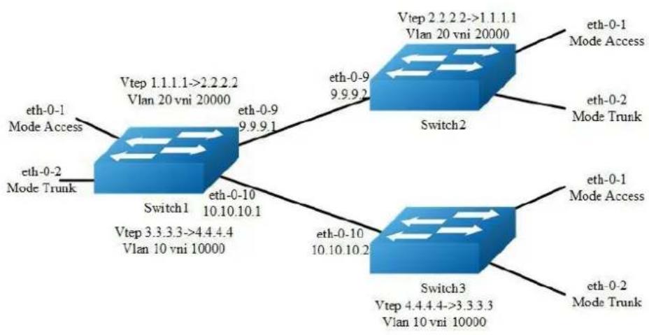
flowchart
graph TD
A["Switch1"] -->|eth-0-1 Mode Access 9.9.9.1 Vtep 1.1.1.1->2.2.2.2 Vlan 20 vni 20000| B["Switch2"]
A -->|eth-0-2 Mode Trunk 9.9.9.2 Vtep 3.3.3.3->4.4.4.4 Vlan 10 vni 10000| C["Switch3"]
B -->|eth-0-9 9.9.9.2 Vtep 2.2.2.2->1.1.1.1 Vlan 20 vni 20000| D["Switch3"]
C -->|eth-0-10 10.10.10.2 Vtep 4.4.4.4->3.3.3.3 Vlan 10 vni 10000| E["Switch3"]
D -->|eth-0-1 Mode Access 9.9.9.2 Vtep 2.2.2.2->1.1.1.1 Vlan 20 vni 20000| F["Switch3"]
E -->|eth-0-1 Mode Trunk 9.9.9.2 Vtep 3.3.3.3->4.4.4.4 Vlan 10 vni 10000| G["Switch3"]
Figure 17-9 Overlay multiple source ip
The following example uses vxlan for overlay configuration. NVGRE and GENEVE configurations are similar with vxlan.
The following configuration should be operated on all switches if the switch ID is not specified.
step 1 Enter the configure mode
Switch# configure terminal
step 2 Enter the vlan configure mode and create vlan, enable overlay for each vlan
Configuring Switch1:
Switch(config)# vlan database
Switch(config-vlan)# vlan 20,10
Switch(config-vlan)# vlan 20 overlay enable
Switch(config-vlan)# vlan 10 overlay enable
Switch(config-vlan)# exit
Configuring Switch2:
Switch(config)# vlan database
Switch(config-vlan)# vlan 20
Switch(config-vlan)# vlan 20 overlay enable
Switch(config-vlan)# exit
Configuring Switch3:
Switch(config)# vlan database
Switch(config-vlan)# vlan 10
Switch(config-vlan)# vlan 10 overlay enable
Switch(config-vlan)# exit
step 3 Enter the interface configure mode and set the attributes of the interface
Interface configuration for Switch1:
Switch(config)# interface eth-0-1
Switch(config-if)# switchport access vlan 20
Switch(config-if)# no shutdown
Switch(config-if)# exit
Switch(config)# interface eth-0-2
Switch(config-if)# switchport mode trunk
Switch(config-if)# switchport trunk allowed vlan add 10
Switch(config-if)# no shutdown
Switch(config-if)# exit
Switch(config)# interface eth-0-9
Switch(config-if)# no switchport
Switch(config-if)# ip address 9.9.9.1/24
Switch(config-if)# overlay uplink enable
Switch(config-if)# no shutdown
Switch(config-if)# exit
Switch(config)# interface eth-0-10
Switch(config-if)# no switchport
Switch(config-if)# ip address 10.10.10.1/24
Switch(config-if)# overlay uplink enable
Switch(config-if)# no shutdown
Switch(config-if)# exit
Switch(config)# interface loopback0
Switch(config-if)# ip address 1.1.1.1/32
Switch(config)# interface loopback1
Switch(config-if)# ip address 3.3.3.3/32
Switch(config-if)# exit
Interface configuration for Switch2:
Switch(config)# interface eth-0-1
Switch(config-if)# switchport access vlan 20
Switch(config-if)# no shutdown
Switch(config-if)# exit
Switch(config)# interface eth-0-2
Switch(config-if)# switchport mode trunk
Switch(config-if)# switchport trunk allowed vlan add 20
Switch(config-if)# no shutdown
Switch(config-if)# exit
Switch(config)# interface eth-0-9
Switch(config-if)# no switchport
Switch(config-if)# ip address 9.9.9.2/24
Switch(config-if)# overlay uplink enable
Switch(config-if)# no shutdown
Switch(config-if)# exit
Switch(config)# interface loopback0
Switch(config-if)# ip address 2.2.2.2/32
Switch(config-if)# exit
Interface configuration for Switch3:
Switch(config)# interface eth-0-1
Switch(config-if)# switchport access vlan 10
Switch(config-if)# no shutdown
Switch(config-if)# exit
Switch(config)# interface eth-0-2
Switch(config-if)# switchport mode trunk
Switch(config-if)# switchport trunk allowed vlan add 10
Switch(config-if)# no shutdown
Switch(config-if)# exit
Switch(config)# interface eth-0-10
Switch(config-if)# no switchport
Switch(config-if)# ip address 10.10.10.2/24
Switch(config-if)# overlay uplink enable
Switch(config-if)# no shutdown
Switch(config-if)# exit
Switch(config)# interface loopback0
Switch(config-if)# ip address 4.4.4.4/32
Switch(config-if)# exit
step 4 Create static routes
Configuring Switch1:
Switch(config)# ip route 2.2.2.0/24 9.9.9.2
Switch(config)# ip route 4.4.4.0/24 10.10.10.2
Configuring Switch2:
Switch(config)# ip route 1.1.1.0/24 9.9.9.1
Configuring Switch3:
Switch(config)# ip route 3.3.3.0/24 10.10.10.1
step 5 Set attributes for overlay
Configuring Switch1:
Switch(config)# overlay
Switch(config-overlay)# source 1.1.1.1
Switch(config-overlay)# remote-vtep 1 ip-address 2.2.2.2 type vxlan
Switch(config-overlay)# remote-vtep 2 ip-address 4.4.4.4 type vxlan src-ip 3.3.3.3
Switch(config-overlay)# vlan 20 vni 20000
Switch(config-overlay)# vlan 10 vni 10000
Switch(config-overlay)# vlan 20 remote-vtep 1
Switch(config-overlay)# vlan 10 remote-vtep 2
Switch(config-overlay)# exit
Configuring Switch2:
Switch(config)# overlay
Switch(config-overlay)# source 2.2.2.2
Switch(config-overlay)# remote-vtep 1 ip-address 1.1.1.1 type vxlan
Switch(config-overlay)# vlan 20 vni 20000
Switch(config-overlay)# vlan 20 remote-vtep 1
Switch(config-overlay)# exit
Configuring Switch3:
Switch(config)# overlay
Switch(config-overlay)# source 4.4.4.4
Switch(config-overlay)# remote-vtep 1 ip-address 3.3.3.3 type vxlan
Switch(config-overlay)# vlan 10 vni 10000
Switch(config-overlay)# vlan 10 remote-vtep 1
Switch(config-overlay)# exit
step 6 Exit the configure mode
Switch(config)# end
step 7 Validation
Display the result on Switch1:
switch# show overlay vlan 20
ECMP Mode : Normal
Source VTEP : 1.1.1.1
VLAN ID : 2
VNI : 20000
EVPN Tunnel Data-fdb Learning : Enable
Remote VTEP NUM: 1
Index: 1, Ip address: 2.2.2.2, Source ip: 1.1.1.1, Type: VxLAN, Protocol: Static
Index: 2, Ip address: 2.2.2.2, Source ip: 3.3.3.3, Type: VxLAN, Protocol: Static
DVR Gateway NUM: 0
Configuring OVERLAY without Horizon Split
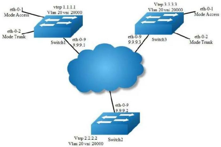
flowchart
graph TD
A["eth-0-1 Mode Access"] --> B["vtep 1.1.1.1 Vlan 20 vni 20000"]
C["eth-0-2 Mode Trunk"] --> D["Switch1"]
B --> E["eth-0-9 9.9.9.1"]
D --> F["eth-0-9 9.9.9.3"]
G["Vtep 3.3.3.3 Vlan 20 vni 20000"] --> H["Switch3"]
I["eth-0-1 Mode Access"] --> J["Switch2"]
K["eth-0-2 Mode Trunk"] --> L["Switch2"]
M["Vtep 2.2.2.2 Vlan 20 vni 20000"] --> N["Switch2"]
Figure 17-10 OVERLAY without Horizon Split
In the following example, there is a tunnel between switch1 and switch2, there is another tunnel between switch2 and switch3. The horizon split is disable on switch2, therefore packets from one tunnel can be forwarded to another tunnel.
The following example uses vxlan for overlay configuration. NVGRE and GENEVE configurations are similar with vxlan.
The following configuration should be operated on all switches if the switch ID is not specified.
step 1 Enter the configure mode
Switch# configure terminal
step 2 Enter the vlan configure mode and create vlan, enable overlay for each vlan
Switch(config)# vlan database
Switch(config-vlan)# vlan 20
Switch(config-vlan)# vlan 20 overlay enable
Switch(config-vlan)# exit
step 3 Enter the interface configure mode and set the attributes of the interface
Interface configuration for Switch1:
Switch(config)# interface eth-0-1
Switch(config-if)# switchport access vlan 20
Switch(config-if)# no shutdown
Switch(config-if)# exit
Switch(config)# interface eth-0-2
Switch(config-if)# switchport mode trunk
Switch(config-if)# switchport trunk allowed vlan add 20
Switch(config-if)# no shutdown
Switch(config-if)# exit
Switch(config)# interface eth-0-9
Switch(config-if)# no switchport
Switch(config-if)# ip address 9.9.9.1/24
Switch(config-if)# overlay uplink enable
Switch(config-if)# no shutdown
Switch(config-if)# exit
Switch(config)# interface loopback0
Switch(config-if)# ip address 1.1.1.1/32
Switch(config-if)# exit
Interface configuration for Switch2:
Switch(config-if)# interface eth-0-9
Switch(config-if)# no switchport
Switch(config-if)# ip address 9.9.9.2/24
Switch(config-if)# overlay uplink enable
Switch(config-if)# no shutdown
Switch(config-if)# exit
Switch(config)# interface loopback0
Switch(config-if)# ip address 2.2.2.2/32
Switch(config-if)# exit
Interface configuration for Switch3:
Switch(config)# interface eth-0-1
Switch(config-if)# switchport access vlan 20
Switch(config-if)# no shutdown
Switch(config-if)# exit
Switch(config)# interface eth-0-2
Switch(config-if)# switchport mode trunk
Switch(config-if)# switchport trunk allowed vlan add 20
Switch(config-if)# no shutdown
Switch(config-if)# exit
Switch(config)# interface eth-0-9
Switch(config-if)# no switchport
Switch(config-if)# ip address 9.9.9.3/24
Switch(config-if)# overlay uplink enable
Switch(config-if)# no shutdown
Switch(config-if)# exit
Switch(config)# interface loopback0
Switch(config-if)# ip address 3.3.3.3/32
Switch(config-if)# exit
step 4 Create a static route
Configuring Switch1:
Switch(config)# ip route 2.2.2.0/24 9.9.9.2
Configuring Switch2:
Switch(config)# ip route 1.1.1.0/24 9.9.9.1
Switch(config)# ip route 3.3.3.3/24 9.9.9.3
Configuring Switch3:
Switch(config)# ip route 2.2.2.0/24 9.9.9.2
step 5 Set attributes for overlay
Configuring Switch1:
Switch(config)# overlay
Switch(config-overlay)# source 1.1.1.1
Switch(config-overlay)# remote-vtep 1 ip-address 2.2.2.2 type vxlan
Switch(config-overlay)# vlan 20 vni 20000
Switch(config-overlay)# vlan 20 remote-vtep 1
Switch(config-overlay)# exit
Configuring Switch2:
Switch(config)# overlay
Switch(config-overlay)# source 2.2.2.2
Switch(config-overlay)# remote-vtep 1 ip-address 1.1.1.1 type vxlan horizon-split-disable
Switch(config-overlay)# remote-vtep 2 ip-address 3.3.3.3 type vxlan horizon-split-disable
Switch(config-overlay)# vlan 20 vni 20000
Switch(config-overlay)# vlan 20 remote-vtep 1
Switch(config-overlay)# vlan 20 remote-vtep 2
Switch(config-overlay)# exit
Configuring Switch3:
Switch(config)# overlay
Switch(config-overlay)# source 3.3.3.3
Switch(config-overlay)# remote-vtep 1 ip-address 2.2.2.2 type vxlan
Switch(config-overlay)# vlan 20 vni 20000
Switch(config-overlay)# vlan 20 remote-vtep 1
Switch(config-overlay)# exit
step 6 Exit the configure mode
Switch(config)# end
step 7 Validation
Display the result on Switch2:
switch# show overlay remote-vtep
Index Type Virtual-Mac IP-Address Source-Ip Split-Horizon Keep-vtag Dscp-
strategy
1 VxLAN - 1.1.1.1 2.2.2.2 Disable Disable
Dscp-copy
2 VxLAN - 3.3.3.3 2.2.2.2 Disable Disable
Dscp-copy
17.4.3 Application cases
N/A
17.5 Configuring Prioprity-based Flow Control
17.5.1 Overview
Function Introduction
In a network path that normally consists of multiple hops between source and destination, lack of feedback between transmitters and receivers at each hop is one of the main causes of unreliability. Transmitters can send packets faster than receivers accept packets, and as the receivers run out of available buffer space to absorb incoming flows, they are forced to silently drop all traffic that exceeds their capacity. These semantics work fine at Layer 2, so long as upper-layer protocols handle drop-detection and retransmission logic.
For applications that cannot build reliability on upper layers, the addition of flow control functions at Layer 2 can offer a solution. Flow control enables feedback
from a receiver to its sender to communicate buffer availability. Its first implementation in IEEE 802.3 Ethernet uses the IEEE 802.3x PAUSE control frames. IEEE 802.3x PAUSE is defined in Annex 31B of the IEEE 802.3 specification. Simply put, a receiver can generate a MAC control frame and send a PAUSE request to a sender when it predicts the potential for buffer overflow. Upon receiving a PAUSE frame, the sender responds by stopping transmission of any new packets until the receiver is ready to accept them again.
IEEE 802.3x PAUSE works as designed, but it suffers a basic disadvantage that limits its field of applicability: after a link is paused, a sender cannot generate any more packets. As obvious as that seems, the consequence is that the application of IEEE 802.3x PAUSE makes an Ethernet segment unsuitable for carrying multiple traffic flows that might require different quality of service (QoS). Thus, enabling IEEE 802.3x PAUSE for one application can affect the performance of other network applications. IEEE 802.1Qbb PFC extends the basic IEEE 802.3x PAUSE semantics to multiple CoSs, enabling applications that require flow control to coexist on the same wire with applications that perform better without it. PFC uses the IEEE 802.1p CoS values in the IEEE 802.1Q VLAN tag to differentiate up to eight CoSs that can be subject to flow control independently.
Principle Description
N/A
17.5.2 Configuration
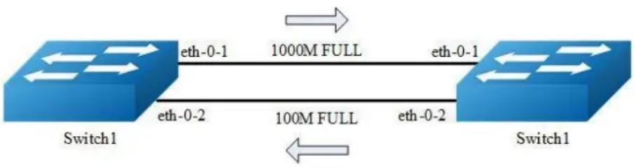
flowchart
graph LR
A["Switch1"] -->|eth-0-1| B["1000M FULL"]
B -->|eth-0-1| C["Switch1"]
A -->|eth-0-2| D["100M FULL"]
D -->|eth-0-2| C
Figure 17-11 Priority-based Flow Control
In the following example, interface eth-0-1 of switch1 and switch2 are connected, interface eth-0-2 of switch1 and switch2 are connected, all interface enable PFC for priority 2/3/4.
The following configuration are same for switch1 and 2.
step 1 Enter the configure mode
Switch# configure terminal
step 2 Enable lldp globally
Switch1(config)# lldp enable
step 3 Enter the interface configure mode and set the attributes of the interface
Switch(config-if)#lldp enable txrx
Switch(config-if)# lldp tlv 8021-org-specific dcbx
Switch(config-if)# priority-flow-control mode on
Switch(config-if)# priority-flow-control enable priority 2 3 4
Switch(config-if)# exit
Switch(config)# interface eth-0-2
Switch(config-if)#lldp enable txrx
Switch(config-if)# lldp tlv 8021-org-specific dcbx
Switch(config-if)# priority-flow-control mode auto
Switch(config-if)# priority-flow-control enable priority 2 3 4
Switch(config-if)# exit
step 4 Exit the configure mode
Switch(config)# end
step 5 Validation
Display the result on Switch1:
switch# show priority-flow-control
Port PFC-enable PFC-enable on priority
admin oper admin oper
eth-0-1 on on 234 234
eth-0-2 auto off 234 off
eth-0-3 off off off off
eth-0-4 off off off off
eth-0-5 off off off off
eth-0-6 off off off off
eth-0-7 off off off off
eth-0-8 off off off off
eth-0-9 off off off off
eth-0-10 off off off off
eth-0-11 off off off off
eth-0-12 off off off off
eth-0-13 off off off off
eth-0-14 off off off off
| eth-0-15 | off | off | off | off |
| eth-0-16 | off | off | off | off |
| eth-0-17 | off | off | off | off |
| eth-0-18 | off | off | off | off |
| eth-0-19 | off | off | off | off |
| eth-0-20 | off | off | off | off |
| eth-0-21 | off | off | off | off |
| eth-0-22 | off | off | off | off |
| eth-0-23 | off | off | off | off |
| eth-0-24 | off | off | off | off |
Display the result on Switch2:
| switch# show priority-flow-control | ||||
| Port | PFC-enable | PFC-enable on priority | ||
| admin | oper | admin | oper | |
| eth-0-1 | on | on | 234 | 234 |
| eth-0-2 | auto | on | 234 | off |
| eth-0-3 | off | off | off | off |
| eth-0-4 | off | off | off | off |
| eth-0-5 | off | off | off | off |
| eth-0-6 | off | off | off | off |
| eth-0-7 | off | off | off | off |
| eth-0-8 | off | off | off | off |
| eth-0-9 | off | off | off | off |
| eth-0-10 | off | off | off | off |
| eth-0-11 | off | off | off | off |
| eth-0-12 | off | off | off | off |
| eth-0-13 | off | off | off | off |
| eth-0-14 | off | off | off | off |
| eth-0-15 | off | off | off | off |
| eth-0-16 | off | off | off | off |
| eth-0-17 | off | off | off | off |
| eth-0-18 | off | off | off | off |
| eth-0-19 | off | off | off | off |
| eth-0-20 | off | off | off | off |
| eth-0-21 | off | off | off | off |
| eth-0-22 | off | off | off | off |
| eth-0-23 | off | off | off | off |
| eth-0-24 | off | off | off | off |
17.5.3 Application cases
N/A
17.6 Configuring OVSDB
17.6.1 Overview
Function Introduction
OVSDB (Open vSwitch Database) is the database for saving configuration on switch. The OVSDB system comprises OVSDB server and OVSDB client. Controller, working as OVSDB client, will configure and query to the OVSDB on switch by OVSDB management protocol. Then all hardware VTEP in the network will be configured and deployed.
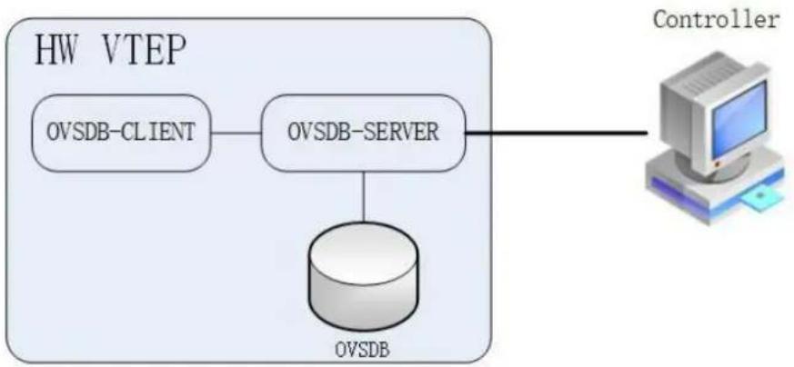
flowchart
graph TD
A["OV SDB-CLIENT"] --> B["OV SDB-SERVER"]
B --> C["Controller"]
D["OV SDB"] --> B
Figure 17-12 OVSDB
After OVSDB function enabled, the switch configured as hardware VTEP, will create and manage OVSDB database. Controller will connect to the OVSDB server on the switch and operate the data in the OVSDB. Then the data in the OVSDB will be translate to VXLAN configuration by the switch.
The supported OVSDB schema tables is list as follows:
| Table Name | Description | Source of Information | Command | Comment |
| Global table | Top-level configuration for a hardware VTEP, include physical switch managed by OVSDB | Switch | ||
| Manager table | Configuration for all connection from controller to OVSDB server | Switch or Controller | ovsdb controller | |
| Physical switch table | Information of physical switch that implements a VTEP | Switch | ||
| Physical port table | Information about OVSDB-managed interfaces | Switch | ovsdb port enable | |
| Logical switch table | Include information about logical switch, which VXLAN tunnel will be configured according to | Controller | ||
| Physical locator table | Include information about switch configured as hardware VTEP. | Controller | ||
| Physical locator set table | Lists service nodes for a logical switch | Controller | ||
| Unicast MACs remote table | Including unicast MAC entities in the virtual network. | Controller | Only support “Unknown-dst” entry | |
| Multicast MACs remote table | Including multicast MAC entities to tunnels (physical locators) in the virtual network. | Controller |
Principle Description
N/A
17.6.2 Configuration
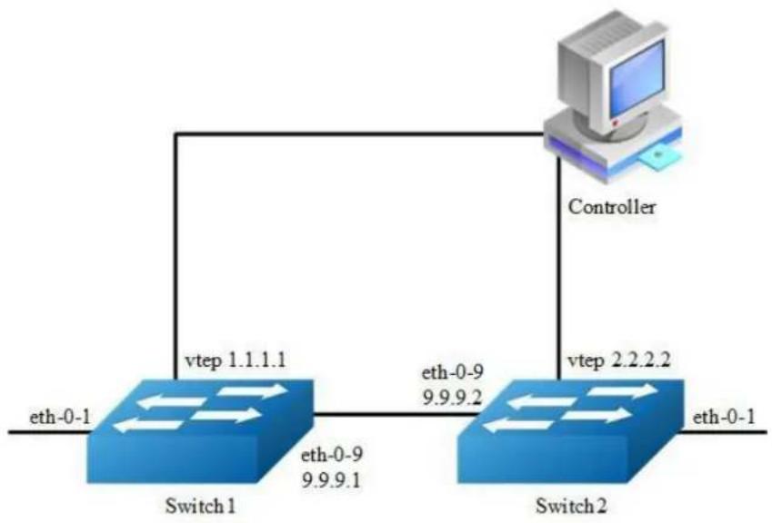
flowchart
graph TD
A["eth-0-1"] --> B["Switch1"]
B --> C["eth-0-9 9.9.9.1"]
B --> D["vtep 1.1.1.1"]
D --> E["Controller"]
F["eth-0-9 9.9.9.2"] --> G["Switch2"]
G --> H["vtep 2.2.2.2"]
H --> I["eth-0-1"]
Figure 17-13 OVSDB
The following configuration should be operated on all switches if the switch ID is not specified.
step 1 Enter the configure mode
Switch# configure terminal
step 2 Enter the interface configure mode and set the attributes of the interface
Interface configuration for Switch1:
Switch(config)# interface eth-0-1
Switch(config-if)# ovsdb port enable
Switch(config-if)# no shutdown
Switch(config-if)# exit
Switch(config)# interface eth-0-9
Switch(config-if)# no switchport
Switch(config-if)# ip address 9.9.9.1/24
Switch(config-if)# overlay uplink enable
Switch(config-if)# no shutdown
Switch(config-if)# exit
Switch(config)# interface loopback0
Switch(config-if)# ip address 1.1.1.1/32
Switch(config-if)# exit
Interface configuration for Switch2:
Switch(config)# interface eth-0-1
Switch(config-if)# ovsdb port enable
Switch(config-if)# no shutdown
Switch(config-if)# exit
Switch(config)# interface eth-0-9
Switch(config-if)# no switchport
Switch(config-if)# ip address 9.9.9.2/24
Switch(config-if)# overlay uplink enable
Switch(config-if)# no shutdown
Switch(config-if)# exit
Switch(config)# interface loopback0
Switch(config-if)# ip address 2.2.2.2/32
Switch(config-if)# exit
step 3 Create static routes
Configuring Switch1:
Switch(config)# ip route 2.2.2.0/24 9.9.9.2
Configuring Switch2:
Switch(config)# ip route 1.1.1.0/24 9.9.9.1
step 4 Set attributes for overlay
Configuring Switch1:
Switch(config)# overlay
Switch(config-overlay)# source 1.1.1.1
Switch(config-overlay)# exit
Configuring Switch2:
Switch(config)# overlay
Switch(config-overlay)# source 2.2.2.2
Switch(config-overlay)# exit
step 5 Enable ovsdb globally
Switch(config)# ovsdb enable
step 6 Exit the configure mode
Switch(config)# end
step 7 Validation
Display the result on Switch1:
Switch# show running
overlay
source 1.1.1.1
!
interface eth-0-1
ovsdb port enable
interface eth-0-9
no switchport
overlay uplink enable
ip address 9.9.9.1/24
interface loopback0
ip address 1.1.1.1/32
!
ovsdb enable
Switch# show ovsdb physical-switch
Physical Switch Name : switch
Management IP address :
Tunnel IP address : 1.1.1.1
17.6.3 Application cases
N/A
17.7 Configuring EFD
17.7.1 Overview
Function Introduction
Elephant Flow Detect (EFD). According to the academic institutions of the actual data center of the study found that more than 80% of the data center bandwidth is occupied by elephant flow, the bandwidth and transmission cache of these flow is large, but not sensitive to delay, which is sensitive to delay The flow caused a great impact. If elephant flow is recognized and some forwarding policies are implemented (such as reducing the forwarding priority of elephant flow appropriately, let mice flow be forwarded first), it can improve the transmission efficiency of data center network.
EFD function can be used to detect some abnormal traffic in the network (such as large bandwidth flow). After detecting, you can encapsulate the characteristics in the protocol packets and sent it to the specified server for further analysis.
Principle Description
terminology:
EFD: Elephant Flow Detect
17.7.2 Configuration
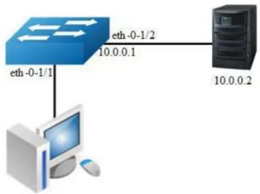
flowchart
graph TD
A["eth-0-1/1"] --> B["Computer"]
C["eth-0-1/2"] --> D["Server"]
style A fill:#333,stroke:#fff,color:#fff
style B fill:#fff,stroke:#000
style C fill:#fff,stroke:#000
style D fill:#fff,stroke:#000
Figure 17-14 EFD
In the following example, it specifies the characteristics field and threshold of the traffic. When the flow rate exceeds the specified threshold, the characteristics of the packets will be encapsulated into the user-defined UDP packets and sent to the server.
step 1 Enter the configure mode
Switch# configure terminal
step 1 Set the parameters for EFC
Specify ipda to calculate packet's hash value
Switch(config)# hash-value global Switch(config-hash-value-global)# efd select ipda
Configure the speed threshold of EFD. The flows which has the rate large than 1000Mbps will be marked as Elephant Flow. The default value is 50Mbps.
Switch(config)# efd detect speed 1000
Enable EFD notify feature, and specify the ipda and UDP port of notification packet
Switch(config)# efd notify enable 10.0.0.2 20007
step 3 Enter the interface configure mode and set the attributes of the interface
Switch(config)# interface eth-0-1/1
Switch(config-if)# efd enable
Switch(config-if)# exit
Switch(config)# int eth-0-1/2
Switch(config-if)# no switchport
Switch(config-if)# ip address 10.0.0.1/24
Switch(config-if)# exit
step 4 Create a static arp entry (Optional)
Switch(config)# arp 10.0.0.2 0.1.2
step 5 Exit the configure mode
Switch(config)# end
step 6 Validation
Switch# show efd configuration
Elephant flow detection configuration information:
Detect rate : 1000 Mbps
Detect granularity : 16B
Detect time interval : 1000 ms
EFD aging time : 120 ms ~ 150 ms
EFD detect packet type : All IP packets
EFD IPC : disable
EFD redirect interface : N/A
EFD flow hash fields : destination-ip
EFD enabled interface :
eth-0-1/1
When the flow received from eth-0-1 exceed 1000Mb, we can find this flow has been learned as EFD flow via the CLI below:
Switch# show efd flow information decap
EFD flow issued at:07:29:40 UTC Mon Aug 01 2016
From:eth-0-1, FlowId: 1701
MACDA:0000.00aa.bbbb, MACSA:0000.00bb.bbbb
IPv4 Packet, IP Protocol is TCP(6)
IPDA:22.22.22.101, IPSA: 11.11.11.11
L4SourcePort:43690, L4DestinationPort:43741
00 00 00 aa bb bb 00 00 00 bb bb bb 08 00 45 00
00 32 00 00 40 00 c8 06 70 35 0b 0b 0b 16 16
16 65 aa aa aa dd aa aa aa dd aa aa aa dd aa aa
aa dd aa aa aa dd aa aa aa dd aa aa aa dd aa aa
Server 10.0.0.2 Tcpdump result:
12:41:28.286993 92:fd:58:d7:8f:00 > 00:00:00:01:00:02, ethertype IPv4 (0x0800), length 60: IP (tos 0x0, ttl 64, id 0, offset 0, flags [DF], proto 17, length: 44) 10.0.0.1.49071 > 10.0.0.2.20007: [udp sum ok] UDP, length 16
0x0000: 0000 0001 0002 92fd 58d7 8f00 0800 4500 ....X....E.
0x0010: 002c 0000 4000 4011 26bf 0a00 0001 0a00 .,.@.@.&.......
0x0020: 0002 bfaf 4e27 0018 b05b 0000 0101 0000 ....N'...[.......
0x0030: 0008 0001 0004 1616 1665 0000 .........e..

NOTE
EFD packet head description. The red part above is part of EFD packet information, specific analysis is as follows:
0000: reserved, no specific meaning. Part of EFD packet head.
01: EFD packt version number, only support 0x01. Part of EFD packet head.
01: EFD flow opcode, 0x01: This flow is first recognized as elephant flow. 0x02: This flow has been recognized as elephant flow before. Part of EFD packet head.
0000 0008: EFD packet data part length(include data part type). Part of EFD packet head.
0001: EFD packet data part type. 0x0001 means data part is IPDA.
0004: EFD packet data part length.
16161665:date part, means IPDA is 22.22.22.101
17.7.3 Application cases
N/A
18 MPLS Configuration Guide
18.1 Configuring LDP
18.1.1 Overview
Function Introduction
This chapter describes how to configure LDP.
A fundamental concept in MPLS is that two Label Switching Routers (LSRs) must agree on the meaning of the labels used to forward traffic between and through them. This common understanding is achieved by using a set of procedures, called label distribution protocol -LDP. The OS software supports these features:
➢ Downstream unsolicited label distribution with liberal retention mode.
Supports control-mode modification.
Supports lsr-id and transport-address modification.
Supports target peer setting.
Supports outbound label filtering.
Supports explicit null label.
This configuration guide will describe the basic configuration of LDP in our system and give some examples for it.
More information about LDP, please see RFC3031 and FRC3036.
Principle Description
N/A
18.1.2 Configuration
LDP Configuration

flowchart
graph LR
A["Lsr-a"] -->|eth-0.1| B["Lsr-b"]
B -->|eth-0.9| C["Lsr-c"]
style A fill:#4CAF50,stroke:#333
style B fill:#4CAF50,stroke:#333
style C fill:#4CAF50,stroke:#333
Figure 18-1 LSP map
The following example will describe how to use LDP to set up a label switching path (LSP) from lsr-a to lsr-c.
The following configuration should be operated on all switches if the switch ID is not specified.
step 1 Enter the configure mode
Switch# configure terminal
step 2 Enter the interface configure mode and set the attributes of the interface
Interface configuration for Lsr-a, interface need enable ldp and enable label switch:
Switch(config)# interface eth-0-17
Switch(config-if)# no switchport
Switch(config-if)# ip address 11.11.17.1/24
Switch(config-if)# enable-ldp
Switch(config-if)# label-switching
Switch(config-if)# exit
Switch(config)# interface loopback0
Switch(config-if)# ip address 1.1.1.1/32
Switch(config-if)# exit
Interface configuration for Lsr-b, interface need enable ldp and enable label switch:
Switch(config)# interface eth-0-17
Switch(config-if)# no switchport
Switch(config-if)# ip address 11.11.17.2/24
Switch(config-if)# enable-ldp
Switch(config-if)# label-switching
Switch(config-if)# exit
Switch(config)# interface eth-0-9
Switch(config-if)# no switchport
Switch(config-if)# ip address 11.11.9.1/24
Switch(config-if)# enable-ldp
Switch(config-if)# label-switching
Switch(config-if)# exit
Switch(config)# interface loopback0
Switch(config-if)# ip address 2.2.2.2/32
Switch(config-if)# exit
Interface configuration for Lsr-c, interface need enable ldp and enable label switch:
Switch(config)# interface eth-0-9
Switch(config-if)# no switchport
Switch(config-if)# ip address 11.11.9.2/24
Switch(config-if)# enable-ldp
Switch(config-if)# label-switching
Switch(config-if)# exit
Switch(config)# interface loopback0
Switch(config-if)# ip address 3.3.3.3/32
Switch(config-if)# exit
step 3 Enable router ldp
Configuration for Lsr-a:
Switch(config)# router ldp
Switch(config-router)# router-id 1.1.1.1
Switch(config-router)# exit
Configuration for Lsr-b:
Switch(config)# router ldp
Switch(config-router)# router-id 2.2.2.2
Switch(config-router)# exit
Configuration for Lsr-c:
Switch(config)# router ldp
Switch(config-router)# router-id 3.3.3.3
Switch(config-router)# exit
step 4 Enable router rip
Switch(config)# router rip
Switch(config-router)# network 0.0.0.0/0
Switch(config-router)# exit
step 5 Exit the configure mode
Switch(config)# end
step 6 Validation
Display the result of Lsr-a ldp session state:
Switch# show ldp session
Peer IP Address IF Name My Role State KeepAlive
2.2.2.2 eth-0-17 Passive OPERATIONAL 30
Display the result of Lsr-b ldp session state:
Switch# show ldp session
Peer IP Address IF Name My Role State KeepAlive
3.3.3.3 eth-0-9 Active OPERATIONAL 30
1.1.1.1 eth-0-17 Active OPERATIONAL 30
Display the result of Lsr-c ldp session state:
Switch# show ldp session
Peer IP Address IF Name My Role State KeepAlive
2.2.2.2 eth-0-9 Passive OPERATIONAL 30
18.2 Configuring MPLS
18.2.1 Overview
Function Introduction
MPLS stands for “Multiprotocol Label Switching”, multiprotocol, because its techniques are applicable to ANY network layer protocol. In this document, however, we focus on the use of IP as the network layer protocol.
Packet headers contain considerably more information than is needed simply to choose the next hop. Choosing the next hop can therefore be thought of as the composition of two functions. The first function partitions the entire set of possible packets into a set of “Forwarding Equivalence Classes (FECs)”. Secondly maps each FEC to a next hop. So far as the forwarding decision is concerned, different packets which get mapped into the same FEC are indistinguishable. All packets which belong to a particular FEC and which travel from a particular node will follow the same path (or if certain kinds of multi-path routing are in use, they will all follow one of a set of paths associated with the FEC). In conventional IP forwarding, a particular router will typically consider two packets to be in the same FEC if there is some address prefix X in that router’s routing tables such that X is the “longest match” for each packet’s destination address. As the packet traverses the network, each hop in turn reexamines the packet and assigns it to a FEC.
In MPLS, the assignment of a particular packet to a particular FEC is done just once, as the packet enters the network. The FEC to which the packet is assigned is
encoded as a short fixed length value known as a “label”. When a packet is forwarded to its next hop, the label is sent along with it; that is, the packets are “labeled” before they are forwarded. At subsequent hops, there is no further analysis of the packet’s network layer header. Rather, the label is used as an index into a table which specifies the next hop, and a new label. The old label is replaced with the new label, and the packet is forwarded to its next hop.
In the MPLS forwarding paradigm, once a packet is assigned to a FEC, no further header analysis is done by subsequent routers; all forwarding is driven by the labels.
Principle Description
N/A
18.2.2 Configuration
MPLS LSP Configuration

flowchart
graph LR
PE1["PE1\neth-0-1"] -->|eth-0-9| P["P\neth-0-17"]
P -->|eth-0-9| PE1
PE1 -->|eth-0-9| P
PE2["PE2\neth-0-1"] -->|eth-0-17| P
Figure 18-2 MPLS LSP model
The following example will describe how to configure MPLS LSP.
The following configuration should be operated on all switches if the switch ID is not specified.
step 1 Enter the configure mode
Switch# configure terminal
step 2 Enter the interface configure mode and set the attributes of the interface
Interface configuration for PE1, interface need enable label switch:
Switch(config)# interface eth-0-9
Switch(config-if)# no switchport
Switch(config-if)# ip address 11.11.9.1/24
Switch(config-if)# label-switching
Switch(config-if)# exit
Switch(config)# interface eth-0-1
Switch(config-if)# no switchport
Switch(config-if)# ip address 10.10.10.1/24
Switch(config-if)# label-switching
Switch(config-if)# exit
Interface configuration for P, interface need enable label switch:
Switch(config)# interface eth-0-9
Switch(config-if)# no switchport
Switch(config-if)# ip address 11.11.9.2/24
Switch(config-if)# label-switching
Switch(config-if)# exit
Switch(config)# interface eth-0-17
Switch(config-if)# no switchport
Switch(config-if)# ip address 11.11.17.2/24
Switch(config-if)# label-switching
Switch(config-if)# exit
Interface configuration for PE2, interface need enable label switch:
Switch(config)# interface eth-0-17
Switch(config-if)# no switchport
Switch(config-if)# ip address 11.11.17.3/24
Switch(config-if)# label-switching
Switch(config-if)# exit
Switch(config)# interface eth-0-1
Switch(config-if)# no switchport
Switch(config-if)# ip address 20.20.20.1/24
Switch(config-if)# label-switching
Switch(config-if)# exit
step 3 Configure static ftn/ilm
Static ftn for PE1:
Switch(config)# mpls ftn-entry 172.22.4.1/24 100 11.11.9.2
Static ilm for P:
Switch(config)#mpls ilm-entry swap 100 11.11.17.3 200
Static ilm for PE2:
Switch(config)# mpls ilm-entry php 200 20.20.20.2
step 4 Validation
Display the ftn lists on PE1:
PE1# show mpls ftn-database
Codes: > - selected FTN, p - stale FTN, B - BGP FTN, K - CLI FTN,
L - LDP FTN, R - RSVP-TE FTN, S - SNMP FTN, I - IGP-Shortcut, U - unknown FTN
Code FEC Out-Label Nexthop Out-Intf
K> 172.22.4.0/24 100 11.11.9.2 eth-0-9
Display the ilm lists on P:
P# show mpls ilm-database
Codes: > - selected ILM, p - stale ILM, B - BGP ILM, K - CLI ILM,
L - LDP ILM, R - RSVP-TE ILM, S - SNMP ILM, I - IGP-Shortcut,
U - unknown ILM
Code FEC I/O Label Nexthop Out-Intf
K> 0.0.0.0/0 100/200 11.11.17.3 eth-0-17
Display the ilm lists on PE2:
PE2# show mpls ilm-database
Codes: > - selected ILM, p - stale ILM, B - BGP ILM, K - CLI ILM,
L - LDP ILM, R - RSVP-TE ILM, S - SNMP ILM, I - IGP-Shortcut,
U - unknown ILM
Code FEC I/O Label Nexthop Out-Intf
K> 0.0.0.0/0 200/3 20.20.20.2 eth-0-1
18.2.3 Application cases
N/A
18.3 Configuring VPLS
18.3.1 Overview
Function Introduction
This chapter describes how to configure VPLS. Virtual Private LAN Service (VPLS) provides a way to enable transparent Layer-2 Ethernet LAN services to geographically dispersed customer sites connected by a Wide Area Network (WAN) by providing support for traditional Layer-2 broadcast and multicast services.
Principle Description
N/A
18.3.2 Configuration
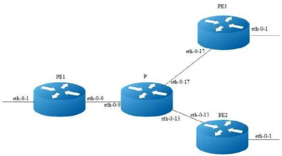
flowchart
graph LR
PE1["PE1\neth-0-1"] -->|eth-0-9| P["p\neth-0-9"]
PE1 -->|eth-0-1| PE2["PE2\neth-0-1"]
PE2 -->|eth-0-13| P
PE2 -->|eth-0-17| PE3["PE3\neth-0-1"]
Figure 18-3 VPLS model
Configuring VPLS using LDP
The following example will describe how to use LDP to configure VPLS:
The following configuration should be operated on all switches if the switch ID is not specified.
step 1 Enter the configure mode
Switch# configure terminal
step 2 Enter the interface configure mode and set the attributes of the interface
Interface configuration for PE1, eth-0-9 need enable ldp and enable label switch:
Switch(config)# interface eth-0-9
Switch(config-if)# no switchport
Switch(config-if)# ip address 11.11.9.1/24
Switch(config-if)# enable-ldp
Switch(config-if)# label-switching
Switch(config-if)# exit
Switch(config)# interface loopback 0
Switch(config-if)# ip address 11.11.1.1/32
Switch(config-if)# exit
Interface configuration for PE2, eth-0-13 need enable ldp and enable label switch:
Switch(config)# interface eth-0-13
Switch(config-if)# no switchport
Switch(config-if)# ip address 11.11.13.4/24
Switch(config-if)# enable-ldp
Switch(config-if)# label-switching
Switch(config-if)# exit
Switch(config)# interface loopback 0
Switch(config-if)# ip address 11.11.4.4/32
Switch(config-if)# exit
Interface configuration for PE3, eth-0-17 need enable ldp and enable label switch:
Switch(config)# interface eth-0-17
Switch(config-if)# no switchport
Switch(config-if)# ip address 11.11.17.3/24
Switch(config-if)# enable-ldp
Switch(config-if)# label-switching
Switch(config-if)# exit
Switch(config)# interface loopback 0
Switch(config-if)# ip address 11.11.3.3/32
Switch(config-if)# exit
Interface configuration for P, interface need enable ldp and enable label switch:
Switch(config)# interface eth-0-9
Switch(config-if)# no switchport
Switch(config-if)# ip address 11.11.9.2/24
Switch(config-if)# enable-ldp
Switch(config-if)# label-switching
Switch(config-if)# exit
Switch(config)# interface eth-0-13
Switch(config-if)# no switchport
Switch(config-if)# ip address 11.11.13.2/24
Switch(config-if)# enable-ldp
Switch(config-if)# label-switching
Switch(config-if)# exit
Switch(config)# interface eth-0-17
Switch(config-if)# no switchport
Switch(config-if)# ip address 11.11.17.2/24
Switch(config-if)# enable-ldp
Switch(config-if)# label-switching
Switch(config-if)# exit
Switch(config)# interface loopback 0
Switch(config-if)# ip address 11.11.2.2/32
Switch(config-if)# exit
step 3 Enable router ldp
LDP configuration for PE1:
Switch(config)# router ldp
Switch(config-router)# router-id 11.11.1.1
Switch(config-router)# targeted-peer 11.11.3.3
Switch(config-router)# targeted-peer 11.11.4.4
Switch(config-router)# transport-address 11.11.1.1
Switch(config-router)# exit
LDP configuration for PE2:
Switch(config)# router ldp
Switch(config-router)# router-id 11.11.4.4
Switch(config-router)# transport-address 11.11.4.4
Switch(config-router)# targeted-peer 11.11.1.1
Switch(config-router)# targeted-peer 11.11.3.3
Switch(config-router)# exit
LDP configuration for PE3:
Switch(config)# router ldp
Switch(config-router)# router-id 11.11.3.3
Switch(config-router)# transport-address 11.11.3.3
Switch(config-router)# targeted-peer 11.11.1.1
Switch(config-router)# targeted-peer 11.11.4.4
Switch(config-router)# exit
LDP configuration for P:
Switch(config)# router ldp
Switch(config-router)# router-id 11.11.2.2
Switch(config-router)# exit
step 4 Enable router rip
Switch(config)# router rip
Switch(config-router)# network 11.11.1.1/16
Switch(config-router)# exit
step 5 Create a VPLS instance
Config PE1, PE2 and PE3 VPLS PW raw mode, and assign their vpls peers.
VPLS instance for PE1:
Switch(config)# mpls vpls v1 100
Switch(config-vpls)# vpls-peer 11.11.3.3 raw
Switch(config-vpls)# vpls-peer 11.11.4.4 raw
Switch(config-vpls)# exit
VPLS instance for PE2:
Switch(config)# mpls vpls v4 100
Switch(config-vpls)# vpls-peer 11.11.1.1 raw
Switch(config-vpls)# vpls-peer 11.11.3.3 raw
Switch(config-vpls)# exit
VPLS instance for PE3:
Switch(config)# mpls vpls v3 100
Switch(config-vpls)# vpls-peer 11.11.1.1 raw
Switch(config-vpls)# vpls-peer 11.11.4.4 raw
Switch(config-vpls)# exit
step 6 bind the interface and the VPLS instance
Config AC of PE1, PE2 and PE3 VLAN access mode.
Interface configuration for PE1:
Switch(config)# interface eth-0-1
Switch(config-if)# switchport mode trunk
Switch(config-if)# mpls-vpls v1 vlan 2
Switch(config-if)# exit
Interface configuration for PE2:
Switch(config)# interface eth-0-1
Switch(config-if)# switchport mode trunk
Switch(config-if)# mpls-vpls v4 vlan 2
Switch(config-if)# exit
Interface configuration for PE3:
Switch(config)# interface eth-0-1
Switch(config-if)# switchport mode trunk
Switch(config-if)# mpls-vpls v3 vlan 2
Switch(config-if)# exit
step 7 Exit the configure mode
Switch(config)# end
step 8 Validation
Use the show ldp session and the show mpls vpls mesh commands respectively to display complete information about the VPLS. Show ldp session command can get LDP peer's state. Show mpls vpls mesh command can get vpls peer's state and the inner labels vpls using. The following are the sample outputs for the show commands displaying VPLS.
Display the result on PE1:
PE1# show ldp session
Peer IP Address TF Name My Role State KeepAlive
11.11.3.3 eth-0-9 Passive OPERATIONAL 30
11.11.4.4 eth-0-9 Passive OPERATIONAL 30
11.11.2.2 eth-0-9 Passive OPERATIONAL 30
PE1# show mpls vpls mesh
VPLS-ID Peer Addr/name In-Label Out-Intf Out-Label Type St
100 11.11.3.3/- 32768 eth-0-9 32768 RAW Up
100 11.11.4.4/- 32773 eth-0-9 32768 RAW Up
Display the result on PE2 :
| PE2# show ldp session | ||||||
| Peer IP Address | IF Name | My Role | State | KeepAlive | ||
| 11.11.1.1 | eth-0-13 | Active | OPERATIONAL | 30 | ||
| 11.11.3.3 | eth-0-13 | Active | OPERATIONAL | 30 | ||
| 11.11.2.2 | eth-0-13 | Passive | OPERATIONAL | 30 | ||
| PE2# show mpls vpls mesh | ||||||
| VPLS-ID | Peer Addr/name | In-Label | Out-Intf | Out-Label | Type | St |
| 100 | 11.11.1.1/- | 32768 | eth-0-13 | 32773 | RAW | Up |
| 100 | 11.11.3.3/- | 32769 | eth-0-13 | 32770 | RAW | Up |
Display the result on PE3 :
| PE3# show ldp session | ||||||
| Peer IP Address | IF Name | My Role | State | KeepAlive | ||
| 11.11.1.1 | eth-0-17 | Active | OPERATIONAL | 30 | ||
| 11.11.4.4 | eth-0-17 | Passive | OPERATIONAL | 30 | ||
| 11.11.2.2 | eth-0-17 | Passive | OPERATIONAL | 30 | ||
| PE3# show mpls vpls mesh | ||||||
| VPLS-ID | Peer Addr/name | In-Label | Out-Intf | Out-Label | Type | St |
| 100 | 11.11.1.1/- | 32768 | eth-0-17 | 32768 | RAW | Up |
| 100 | 11.11.4.4/- | 32770 | eth-0-17 | 32769 | RAW | Up |
Display the result on P :
| P# show ldp session | ||||
| Peer IP Address | IF Name | My Role | State | KeepAlive |
| 11.11.1.1 | eth-0-9 | Active | OPERATIONAL | 30 |
| 11.11.3.3 | eth-0-17 | Active | OPERATIONAL | 30 |
| 11.11.4.4 | eth-0-13 | Active | OPERATIONAL | 30 |
Configuring VPLS using static command
The following example will describe how to configure static VPLS:
The following configuration should be operated on all switches if the switch ID is not specified.
step 1 Enter the configure mode
Switch# configure terminal
step 2 Enter the interface configure mode and set the attributes of the interface
Interface configuration for PE1, eth-0-9 need enable label switch:
Switch(config)# interface eth-0-9
Switch(config-if)# no switchport
Switch(config-if)# ip address 11.11.9.1/24
Switch(config-if)# label-switching
Switch(config-if)# exit
Interface configuration for PE2, eth-0-13 need enable label switch:
Switch(config)# interface eth-0-13
Switch(config-if)# no switchport
Switch(config-if)# ip address 11.11.13.1/24
Switch(config-if)# label-switching
Switch(config-if)# exit
Interface configuration for PE3, eth-0-17 need enable label switch:
Switch(config)# interface eth-0-17
Switch(config-if)# no switchport
Switch(config-if)# ip address 11.11.17.1/24
Switch(config-if)# label-switching
Switch(config-if)# exit
Interface configuration for P, eth-0-9, eth-0-13 and eth-0-17 need enable label switch:
Switch(config)# interface eth-0-9
Switch(config-if)# no switchport
Switch(config-if)# ip address 11.11.9.2/24
Switch(config-if)# label-switching
Switch(config-if)# exit
Switch(config)# interface eth-0-17
Switch(config-if)# no switchport
Switch(config-if)# ip address 11.11.17.2/24
Switch(config-if)# label-switching
Switch(config-if)# exit
Switch(config)# interface eth-0-13
Switch(config-if)# no switchport
Switch(config-if)# ip address 11.11.13.2/24
Switch(config-if)# label-switching
Switch(config-if)# exit
step 3 Configure ftn entry
Interface configuration for PE1:
Switch(config)# mpls ftn-entry 11.11.17.1/24 97 11.11.9.2
Switch(config)# mpls ftn-entry 11.11.13.1/24 93 11.11.9.2
Interface configuration for PE2:
Switch(config)# mpls ftn-entry 11.11.9.1/32 44 11.11.13.2
Interface configuration for PE3:
Switch(config)#mpls ftn-entry 11.11.9.1/32 33 11.11.17.2
step 4 Create a VPLS instance
Config PE1, PE2 and PE3 VPLS PW raw mode, and assign their vpls peers.
VPLS instance for PE1:
Switch(config)# mpls vpls vpls1 1
Switch(config-vpls)# vpls-peer 11.11.17.1 raw manual
Switch(config-vpls)# vpls-peer 11.11.13.1 raw manual
VPLS instance for PE2:
Switch(config)# mpls vpls vpls1 1
Switch(config-vpls)# vpls-peer 11.11.9.1 raw manual
VPLS instance for PE3:
Switch(config)# mpls vpls vpls1 1
Switch(config-vpls)# vpls-peer 11.11.9.1 raw manual
step 5 bind the interface and the VPLS instance
Config AC of PE1, PE2 and PE3 VLAN access mode.
Interface configuration for PE1:
Switch(config)# interface eth-0-1
Switch(config-if)# switchport mode trunk
Switch(config-if)# mpls-vpls vpls1 vlan 100
Switch(config-if)# exit
Interface configuration for PE2:
Switch(config)# interface eth-0-1
Switch(config-if)# switchport mode trunk
Switch(config-if)# mpls-vpls vpls1 vlan 100
Switch(config-if)# exit
Interface configuration for PE3:
Switch(config)#interface eth-0-1
Switch(config-if)# switchport mode trunk
Switch(config-if)# mpls-vpls vpls1 vlan 100
Switch(config-if)# exit
step 6 Configure VPLS FIB
VPLS FIB for PE1:
Switch(config)# vpls-fib-add vpls1 peer 11.11.17.1 103 31
Switch(config)# vpls-fib-add vpls1 peer 11.11.13.1 102 201
VPLS FIB for PE2:
Switch(config)# vpls-fib-add vpls1 peer 11.11.9.1 201 102
VPLS FIB for PE3:
Switch(config)# vpls-fib-add vpls1 peer 11.11.9.1 31 103
step 7 Configure static ilm
Static ilm for P:
Switch(config)# mpls ilm-entry php 97 11.11.17.1
Switch(config)# mpls ilm-entry php 93 11.11.13.1
Switch(config)# mpls ilm-entry php 33 11.11.9.1
Switch(config)# mpls ilm-entry php 44 11.11.9.1
step 8 Exit the configure mode
Switch(config)# end
step 9 Validation
Show mpls vpls mesh command can get vpls peer's state and the inner labels vpls using.
Display the result on PE1:
PE1# show mpls vpls mesh
VPLS-ID Peer Addr/name In-Label Out-Intf Out-Label Type St
1 11.11.13.1/- 102 eth-0-9 201 RAW Up
1 11.11.17.1/- 103 eth-0-9 31 RAW Up
Display the result on PE2:
PE2# show mpls vpls mesh
VPLS-ID Peer Addr/name In-Label Out-Intf Out-Label Type St
1 11.11.9.1/- 201 eth-0-13 102 RAW Up
Display the result on PE3:
PE3# show mpls vpls mesh
VPLS-ID Peer Addr/name In-Label Out-Intf Out-Label Type St
1 11.11.9.1/- 31 eth-0-17 103 RAW Up
Display the result on P:
P# show mpls ilm-database
Codes: > - selected ILM, p - stale ILM, B - BGP ILM, K - CLI ILM,
L - LDP ILM, R - RSVP-TE ILM, S - SNMP ILM, I - IGP-Shortcut,
U - unknown ILM
Code FEC I/O Label Nexthop Out-Intf
K> 0.0.0.0/0 33/3 11.11.9.1 eth-0-9
K> 0.0.0.0/0 44/3 11.11.9.1 eth-0-9
| K> | 0.0.0.0/0 | 93/3 | 11.11.13.1 | eth-0-13 |
| K> | 0.0.0.0/0 | 97/3 | 11.11.17.1 | eth-0-17 |
Configuring Tunnel L2 protocol packets by VPLS
Customers at different sites connected across a service-provider network need to run various Layer 2 protocols to scale their topology to include all remote sites, as well as the local sites. STP must run properly, and build a proper spanning tree that includes the local site and all remote sites across the service-provider infrastructure.
The following example will display how to tunnel STP protocol packets by vpls. Users can configure other L2 protocol packets like that. The following configuration is also based on Figure VPLS model topology.
The following configuration should be operated on all switches if the switch ID is not specified.
step 1 Enter the configure mode
Switch# configure terminal
step 2 Enable L2 protocol globally
Switch(config)# 12protocol enable
step 3 Enter the interface configure mode and set the attributes of the interface
Interface configuration for PE1, eth-0-9 need enable ldp and enable label switch:
Switch(config)# interface eth-0-9
Switch(config-if)# no switchport
Switch(config-if)# ip address 11.11.9.1/24
Switch(config-if)# enable-ldp
Switch(config-if)# label-switching
Switch(config-if)# exit
Switch(config)# interface loopback 0
Switch(config-if)# ip address 11.11.1.1/32
Switch(config-if)# exit
Interface configuration for PE2, eth-0-13 need enable ldp and enable label switch:
Switch(config)# interface eth-0-13
Switch(config-if)# no switchport
Switch(config-if)# ip add 11.11.13.4/24
Switch(config-if)# enable-ldp
Switch(config-if)# label-switching
Switch(config-if)# exit
Switch(config)# interface loopback 0
Switch(config-if)# ip address 11.11.4.4/32
Switch(config-if)# exit
Interface configuration for PE3, eth-0-17 need enable ldp and enable label switch:
Switch(config)# interface eth-0-17
Switch(config-if)# no switchport
Switch(config-if)# ip address 11.11.17.3/24
Switch(config-if)# enable-ldp
Switch(config-if)# label-switching
Switch(config-if)# exit
Switch(config)# interface loopback 0
Switch(config-if)# ip address 11.11.3.3/32
Switch(config-if)# exit
Interface configuration for P, interface need enable ldp and enable label switch:
Switch(config)# interface eth-0-9
Switch(config-if)# no switchport
Switch(config-if)# ip address 11.11.9.2/24
Switch(config-if)# enable-ldp
Switch(config-if)# label-switching
Switch(config-if)# exit
Switch(config)# interface eth-0-13
Switch(config-if)# no switchport
Switch(config-if)# ip address 11.11.13.2/24
Switch(config-if)# enable-ldp
Switch(config-if)# label-switching
Switch(config-if)# exit
Switch(config)# interface eth-0-17
Switch(config-if)# no switchport
Switch(config-if)# ip address 11.11.17.2/24
Switch(config-if)# enable-ldp
Switch(config-if)# label-switching
Switch(config-if)# exit
Switch(config)# interface loopback 0
Switch(config-if)# ip address 11.11.2.2/32
Switch(config-if)# exit
step 4 Enable router ldp
LDP configuration for PE1:
Switch(config)# router ldp
Switch(config-router)# router-id 11.11.1.1
Switch(config-router)# targeted-peer 11.11.3.3
Switch(config-router)# targeted-peer 11.11.4.4
Switch(config-router)# transport-address 11.11.1.1
Switch(config-router)# exit
LDP configuration for PE2:
Switch(config)# router ldp
Switch(config-router)# router-id 11.11.4.4
Switch(config-router)# transport-address 11.11.4.4
Switch(config-router)# targeted-peer 11.11.1.1
Switch(config-router)# targeted-peer 11.11.3.3
Switch(config-router)# exit
LDP configuration for PE3:
Switch(config)# router ldp
Switch(config-router)# router-id 11.11.3.3
Switch(config-router)# transport-address 11.11.3.3
Switch(config-router)# targeted-peer 11.11.1.1
Switch(config-router)# targeted-peer 11.11.4.4
Switch(config-router)# exit
LDP configuration for P:
Switch(config)# router ldp
Switch(config-router)# router-id 11.11.2.2
Switch(config-router)# exit
step 5 Enable router rip
RIP configuration for PE1/PE2/PE3:
Switch(config)# router rip
Switch(config-router)# network 11.11.1.1/16
Switch(config-router)# exit
step 6 Create a VPLS instance
Config PE1, PE2 and PE3 VPLS PW raw mode, and assign their vpls peers.
VPLS instance for PE1:
Switch(config)# mpls vpls v1 100
Switch(config-vpls)# vpls-peer 11.11.3.3 raw
Switch(config-vpls)# vpls-peer 11.11.4.4 raw
Switch(config-vpls)# exit
VPLS instance for PE2:
Switch(config)# mpls vpls v4 100
Switch(config-vpls)# vpls-peer 11.11.1.1 raw
Switch(config-vpls)# vpls-peer 11.11.3.3 raw
Switch(config-vpls)# exit
VPLS instance for PE3:
Switch(config)# mpls vpls v3 100
Switch(config-vpls)# vpls-peer 11.11.1.1 raw
Switch(config-vpls)# vpls-peer 11.11.4.4 raw
Switch(config-vpls)# exit
step 7 bind the interface and the VPLS instance
Config AC of PE1, PE2 and PE3 ethernet access mode.
Interface configuration for PE1:
Switch(config)# interface eth-0-1
Switch(config-if)# mpls-vpls v1 ethernet
Switch(config-if)# l2protocol stp tunnel
Switch(config-if)# exit
Interface configuration for PE2:
Switch(config)# interface eth-0-1
Switch(config-if)# mpls-vpls v4 ethernet
Switch(config-if)# l2protocol stp tunnel
Switch(config-if)# exit
Interface configuration for PE3:
Switch(config)# interface eth-0-1
Switch(config-if)# mpls-vpls v3 ethernet
Switch(config-if)# l2protocol stp tunnel
Switch(config-if)# exit
step 8 Exit the configure mode
Switch(config)# end
Configuring static MAC entries for VPLS
In a Virtual Switch Instance (VSI), if a PE receives a packet with an unknown destination MAC address, the PE will flood the packet. User can configure static MAC entries to specify the interface or peer node to which the received packets to be forwarded. The following example shows how to configure static MAC entries for a VSI. The following configuration is based on Figure VPLS model topology.
The following configuration should be operated on all switches if the switch ID is not specified.
step 1 Enter the configure mode
Switch# configure terminal
step 2 Enter the interface configure mode and set the attributes of the interface
Interface configuration for PE1, eth-0-9 need enable ldp and enable label switch:
Switch(config)# interface eth-0-9
Switch(config-if)# no switchport
Switch(config-if)# ip address 11.11.9.1/24
Switch(config-if)# enable-ldp
Switch(config-if)# label-switching
Switch(config-if)# exit
Switch(config)# interface loopback 0
Switch(config-if)# ip address 11.11.1.1/32
Switch(config-if)# exit
Interface configuration for PE2, eth-0-13 need enable ldp and enable label switch:
Switch(config)# interface eth-0-13
Switch(config-if)# no switchport
Switch(config-if)# ip add 11.11.13.4/24
Switch(config-if)# enable-ldp
Switch(config-if)# label-switching
Switch(config-if)# exit
Switch(config)# interface loopback 0
Switch(config-if)# ip address 11.11.4.4/32
Switch(config-if)# exit
Interface configuration for PE3, eth-0-17 need enable ldp and enable label switch:
Switch(config)# interface eth-0-17
Switch(config-if)# no switchport
Switch(config-if)# ip address 11.11.17.3/24
Switch(config-if)# enable-ldp
Switch(config-if)# label-switching
Switch(config-if)# exit
Switch(config)# interface loopback 0
Switch(config-if)# ip address 11.11.3.3/32
Switch(config-if)# exit
Interface configuration for P, interface need enable ldp and enable label switch:
Switch(config)# interface eth-0-9
Switch(config-if)# no switchport
Switch(config-if)# ip address 11.11.9.2/24
Switch(config-if)# enable-ldp
Switch(config-if)# label-switching
Switch(config-if)# exit
Switch(config)# interface eth-0-13
Switch(config-if)# no switchport
Switch(config-if)# ip address 11.11.13.2/24
Switch(config-if)# enable-ldp
Switch(config-if)# label-switching
Switch(config-if)# exit
Switch(config)# interface eth-0-17
Switch(config-if)# no switchport
Switch(config-if)# ip address 11.11.17.2/24
Switch(config-if)# enable-ldp
Switch(config-if)# label-switching
Switch(config-if)# exit
Switch(config)# interface loopback 0
Switch(config-if)# ip address 11.11.2.2/32
Switch(config-if)# exit
step 3 Enable router ldp
LDP configuration for PE1:
Switch(config)# router ldp
Switch(config-router)# router-id 11.11.1.1
Switch(config-router)# targeted-peer 11.11.3.3
Switch(config-router)# targeted-peer 11.11.4.4
Switch(config-router)# transport-address 11.11.1.1
Switch(config-router)# exit
LDP configuration for PE2:
Switch(config)# router ldp
Switch(config-router)# router-id 11.11.4.4
Switch(config-router)# transport-address 11.11.4.4
Switch(config-router)# targeted-peer 11.11.1.1
Switch(config-router)# targeted-peer 11.11.3.3
Switch(config-router)# exit
LDP configuration for PE3:
Switch(config)# router ldp
Switch(config-router)# router-id 11.11.3.3
Switch(config-router)# transport-address 11.11.3.3
Switch(config-router)# targeted-peer 11.11.1.1
Switch(config-router)# targeted-peer 11.11.4.4
Switch(config-router)# exit
LDP configuration for P:
Switch(config)# router ldp
Switch(config-router)# router-id 11.11.2.2
Switch(config-router)# exit
step 4 Enable router rip
Switch(config)# router rip
Switch(config-router)# network 11.11.1.1/16
Switch(config-router)# exit
step 5 Create a VPLS instance
Config PE1, PE2 and PE3 VPLS PW raw mode, and assign their vpls peers.
VPLS instance for PE1:
Switch(config)# mpls vpls v1 100
Switch(config-vpls)# vpls-peer 11.11.3.3 raw
Switch(config-vpls)# vpls-peer 11.11.4.4 raw
Switch(config-vpls)# mac-address-table 0000.0000.0001 forward eth-0-1
Switch(config-vpls)# mac-address-table 0000.0000.0003 forward peer 11.11.3.3
Switch(config-vpls)# mac-address-table 0000.0000.0004 forward peer 11.11.4.4
Switch(config-vpls)# exit
VPLS instance for PE2:
Switch(config)# mpls vpls v4 100
Switch(config-vpls)# vpls-peer 11.11.1.1 raw
Switch(config-vpls)# vpls-peer 11.11.3.3 raw
Switch(config-vpls)# mac-address-table 0000.0000.0004 forward eth-0-1
Switch(config-vpls)# mac-address-table 0000.0000.0001 forward peer 11.11.1.1
Switch(config-vpls)# mac-address-table 0000.0000.0003 forward peer 11.11.3.3
Switch(config-vpls)# exit
VPLS instance for PE3:
Switch(config)# mpls vpls v3 100
Switch(config-vpls)# vpls-peer 11.11.1.1 raw
Switch(config-vpls)# vpls-peer 11.11.4.4 raw
Switch(config-vpls)# mac-address-table 0000.0000.0003 forward eth-0-1
Switch(config-vpls)# mac-address-table 0000.0000.0001 forward peer 11.11.1.1
Switch(config-vpls)# mac-address-table 0000.0000.0004 forward peer 11.11.4.4
Switch(config-vpls)# exit
step 6 bind the interface and the VPLS instance
Config AC of PE1, PE2 and PE3 ethernet access mode.
Interface configuration for PE1:
Switch(config)# interface eth-0-1
Switch(config-if)# mpls-vpls v1 ethernet
Switch(config-if)# exit
Interface configuration for PE2:
Switch(config)# interface eth-0-1
Switch(config-if)# mpls-vpls v4 ethernet
Switch(config-if)# exit
Interface configuration for PE3:
Switch(config)# interface eth-0-1
Switch(config-if)# mpls-vpls v3 ethernet
Switch(config-if)# exit
step 7 Exit the configure mode
Switch(config)# end
step 8 Validation
Use the show mac address-table vpls to display complete information about the VPLS MAC entries. The following are the sample outputs for the show command.
Display the result on PE1:
PE1# show mac address-table vpls
vpls peer mac static
vl eth-0-1 0000.0000.0001 1
vl 11.11.3.3 0000.0000.0003 1
vl 11.11.4.4 0000.0000.0004 1
Display the result on PE2:
PE2# show mac address-table vpls
vpls peer mac static
vl eth-0-1 0000.0000.0004 1
vl 11.11.1.1 0000.0000.0001 1
vl 11.11.3.3 0000.0000.0003 1
Display the result on PE3:
PE3# show mac address-table vpls
vpls peer mac static
vl eth-0-1 0000.0000.0003 1
vl 11.11.1.1 0000.0000.0001 1
vl 11.11.4.4 0000.0000.0004 1
18.3.3 Application cases
N/A
18.4 Configuring VPWS
18.4.1 Overview
Function Introduction
This chapter describes how to configure VPWS. The MPLS L2CIRCUIT is a point-to-point Layer 2 connection transported by means of Multiprotocol Label Switching
(MPLS) on the service provider's network. The Layer 2 circuit is transported over a single Label Switched Path (LSP) tunnel between two Provider Edge (PE) routers.
Principle Description
N/A
18.4.2 Configuration
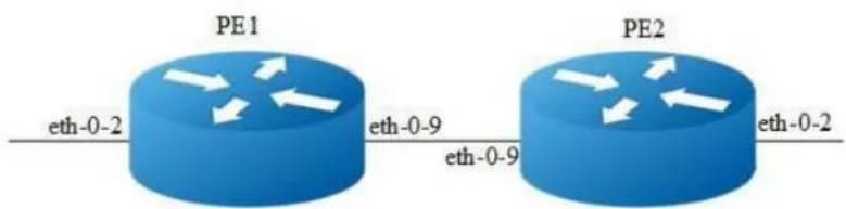
flowchart
graph LR
PE1["PE1\neth-0-2"] --> PE1
PE1 --> PE2["PE2\neth-0-2"]
PE2 --> PE1
PE2 --> PE1
PE1 -->|eth-0-9| PE2
PE2 -->|eth-0-9| PE1
Figure 18-4 Topology of vpws configuration
Configuring VPWS using LDP
The Virtual Circuit module is a part of the LDP module. It is based on the IETF drafts proposed by Martini, et al [L2TRANS]. The Virtual Circuits module sets up virtual circuits for transporting Layer 2 protocols across an MPLS network. This chapter includes a step-by-step configuration of VPWS.
The following configuration should be operated on all switches if the switch ID is not specified.
step 1 Enter the configure mode
Switch# configure terminal
step 2 Enter the interface configure mode and set the attributes of the interface
Interface configuration for PE1:
Switch(config)# interface eth-0-2
Switch(config-if)# mpls-l2-circuit t1 ethernet
Switch(config-if)# exit
Switch(config)# interface loopback 0
Switch(config-if)# ip address 192.168.10.10/32
Switch(config-if)# exit
Switch(config)# interface eth-0-9
Switch(config-if)# no switchport
Switch(config-if)# ip address 8.8.8.1/24
Switch(config-if)# enable-ldp
Switch(config-if)# label-switching
Switch(config-if)# exit
Interface configuration for PE2:
Switch(config)# interface eth-0-2
Switch(config-if)# mpls-l2-circuit t1 ethernet
Switch(config-if)# exit
Switch(config)# interface loopback 0
Switch(config-if)# ip address 192.168.11.10/32
Switch(config-if)# exit
Switch(config)# interface eth-0-9
Switch(config-if)# no switchport
Switch(config-if)# ip address 8.8.8.2/24
Switch(config-if)# enable-ldp
Switch(config-if)# label-switching
Switch(config-if)# exit
step 3 Enable router ldp
LDP configuration for PE1:
Switch(config)# router ldp
Switch(config-router)# router-id 192.168.10.10
Switch(config-router)# targeted-peer 192.168.11.10
Switch(config-router)# exit
LDP configuration for PE2:
PE2(config)# router ldp
PE2(config-router)# router-id 192.168.11.10
PE2(config-router)# targeted-peer 192.168.10.10
PE2(config-router)# exit
step 4 Configure VPWS VC ID
VC ID configuration for PE1:
PE1(config)# mpls 12-circuit t1 200 192.168.11.10 raw
VC ID configuration for PE2:
PE2(config)# mpls 12-circuit t1 200 192.168.10.10 raw
step 4 Enable router rip
Switch(config)# router rip
Switch(config-router)# network 0.0.0.0/0
Switch(config-router)# exit
step 5 Exit the configure mode
Switch(config)# end
step 6 Validation
Use the show mpls l2-circuit and the show mpls vc-table commands respectively to display complete information about the Layer-2 Virtual Circuit. The following are the sample outputs for the show commands displaying Layer-2 virtual circuit information.
Display the result on PE1: ?
PE1# show mpls 12-circuit
VC-Name VC-ID Interface AC-type VLAN PW-mode Manual
t1 200 eth-0-2 Ethernet N/A Raw No
PE1# show mpls vc-table
VC-ID PW Intl AC Intl L/R Label EndPoint Status Manual
200 eth-0-9 eth-0-2 32768/32768 192.168.11.10 Active No
Display the result on PE2:
PE2# show mpls 12-circuit
VC-Name VC-ID Interface AC-type VLAN PW-mode Manual
t1 200 eth-0-2 Ethernet N/A Raw No
PE2# show mpls vc-table
VC-ID PW Intf AC Intf L/R Label EndPoint Status Manual
200 eth-0-9 eth-0-2 32768/32768 192.168.10.10 Active No
VC configuration using static command
The following example will describe how to configure static VPWS
The following configuration should be operated on all switches if the switch ID is not specified.
step 1 Enter the configure mode
Switch# configure terminal
step 2 Enter the interface configure mode and set the attributes of the interface
Interface configuration for PE1:
Switch(config)# interface eth-0-2
Switch(config-if)# mpls-l2-circuit t2 ethernet
Switch(config-if)# exit
Switch(config)# interface loopback 0
Switch(config-if)# ip address 192.168.10.10/32
Switch(config-if)# exit
Switch(config)# interface eth-0-9
Switch(config-if)# no switchport
Switch(config-if)# ip address 8.8.8.1/24
Switch(config-if)# label-switching
Switch(config-if)# exit
Interface configuration for PE3:
Switch(config)# interface eth-0-2
Switch(config-if)# mpls-l2-circuit t2 ethernet
Switch(config-if)# exit
Switch(config)# interface loopback 0
Switch(config-if)# ip address 192.168.11.10/32
Switch(config-if)# exit
Switch(config)# interface eth-0-9
Switch(config-if)# no switchport
Switch(config-if)# ip address 8.8.8.2/24
Switch(config-if)# label-switching
Switch(config-if)# exit
step 3 Configure ftn entry
FTN entry for PE1:
Switch(config)# mpls ftn-entry 192.168.11.1/24 111 8.8.8.2
FTN entry for PE2: ?
? Switch(config)# mpls ftn-entry 192.168.10.1/24 222 8.8.8.1
step 4 Configure static ilm
Static ilm for PE1:
Switch(config)# mpls ilm-entry pop 212
Static ilm for PE2:
PE2(config)#mpls ilm-entry pop 111
step 5 Configure VPWS VC ID
VC ID configuration for PE1:
Switch(config)# mpls 12-circuit t2 201 192.168.11.10 raw manual
Switch(config)# mpls 12-circuit-fib-entry t2 44 33
VC ID configuration for PE2:
Switch(config)# mpls l2-circuit t2 201 192.168.10.10 raw manual
Switch(config)# mpls l2-circuit-fib-entry t2 33 44
step 6 Exit the configure mode
Switch(config)# end
step 7 Validation
Use the show mpls l2circuit and the show mpls vc-table commands respectively to display complete information about the Layer-2 Virtual Circuit. The following are the sample outputs for the show commands displaying Layer-2 virtual circuit information.
Display the result on PE1:
PE1# show mpls 12-circuit
VC-Name VC-ID Interface AC-type VLAN PW-mode Manual
t2 201 eth-0-2 Ethernet N/A Raw Yes
PE1# show mpls vc-table
VC-ID PW Intl AC Intl L/R Label EndPoint Status Manual
201 eth-0-9 eth-0-2 44/33 192.168.11.10 Active Yes
Display the result on PE2:
PE2# show mpls 12-circuit
VC-Name VC-ID Interface AC-type VLAN PW-mode Manual
t2 201 eth-0-2 Ethernet N/A Raw Yes
PE2# show mpls vc-table
VC-ID PW Intf AC Intf L/R Label EndPoint Status Manual
201 eth-0-9 eth-0-2 33/44 192.168.10.10 Active Yes
Configuring Tunnel L2 protocol packets by VPWS
Customers at different sites connected across a service-provider network need to run various Layer 2 protocols to scale their topology to include all remote sites, as well as the local sites. STP must run properly, and build a proper spanning tree that includes the local site and all remote sites across the service-provider infrastructure. The following example will display how to tunnel STP protocol packets by vpws. Users can configure other L2 protocol packets like that. The following configuration is also based on chart 1.
The following configuration should be operated on all switches if the switch ID is not specified.
step 1 Enter the configure mode
Switch# configure terminal
step 2 Enable L2 protocol globally
Switch(config)# 12protocol enable
step 3 Enter the interface configure mode and set the attributes of the interface
Interface configuration for PE1:
Switch(config)# interface eth-0-2
Switch(config-if)# mpls-l2-circuit t1 ethernet
Switch(config-if)# 12protocol stp tunnel
Switch(config-if)# exit
Switch(config)# interface loopback 0
Switch(config-if)# ip address 192.168.10.10/32
Switch(config-if)# exit
Switch(config)# interface eth-0-9
Switch(config-if)# no switchport
Switch(config-if)# ip address 8.8.8.1/24
Switch(config-if)# enable-ldp
Switch(config-if)# label-switching
Switch(config-if)# exit
Interface configuration for PE2:
Switch#configure terminal
Switch(config)# 12protocol enable
Switch(config)# interface eth-0-2
Switch(config-if)# mpls-12-circuit t1 ethernet
Switch(config-if)# 12protocol stp tunnel
Switch(config-if)# exit
Switch(config)# interface loopback 0
Switch(config-if)# ip address 192.168.11.10/32
Switch(config-if)# exit
Switch(config)# interface eth-0-9
Switch(config-if)# no switchport
Switch(config-if)# ip address 8.8.8.2/24
Switch(config-if)# enable-ldp
Switch(config-if)# label-switching
Switch(config-if)# exit
step 4 Enable router ldp
LDP configuration for PE1:
Switch(config)# router ldp
Switch(config-router)# router-id 192.168.10.10
Switch(config-router)# targeted-peer 192.168.11.10
Switch(config-router)# exit
LDP configuration for PE2:
Switch(config)# router ldp
Switch(config-router)# router-id 192.168.11.10
Switch(config-router)# targeted-peer 192.168.10.10
Switch(config-router)# exit
step 4 Configure VPWS VC ID
VC ID configuration for PE1:
switch(config)# mpls 12-circuit t1 200 192.168.11.10 raw
VC ID configuration for PE2:
switch(config)# mpls 12-circuit t1 200 192.168.10.10 raw
step 5 Enable router rip
switch(config)# router rip
switch(config-router)# network 0.0.0.0/0
switch(config-router)# exit
step 6 Exit the configure mode
Switch(config)# end
18.4.3 Application cases
N/A
18.5 Configuring MPLS QoS
18.5.1 Overview
Function Introduction
MPLS QoS is the important part of QoS network, which is usually implemented by DiffServ model.
MPLS use labels to take the place of routes, which is powerful, flexible and can satisfy all kinds of requirements.
Principle Description
18.5.2 MPLS LSP Model
MPLS LSP modelcontain three models: Uniform、Pipe、Short Pipe。
Uniform model: The packets on IP network and MPLS network have the same priority, which means the priority is take effect golbally. On the ingress device, the packets will be added labels and the exp will be mapped from dscp. On the egress device, the dscp of the packets will be mapped from exp.
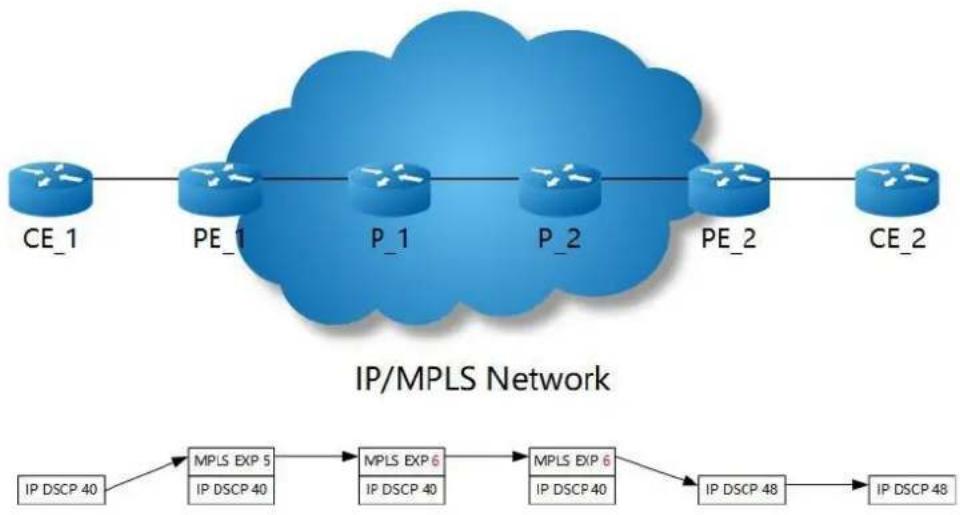
flowchart
graph LR
CE1["CE_1"] --> PE1["PE_1"]
PE1 --> P1["P_1"]
P1 --> P2["P_2"]
P2 --> PE2["PE_2"]
PE2 --> CE2["CE_2"]
CE2 --> PE2
subgraph "IP/MPLS Network"
MPLS_EXP5["MPLS EXP 5"] --> MPLS_EXP6["MPLS EXP 6"]
MPLS_EXP6 --> MPLS_EXP40["MPLS EXP 40"]
MPLS_EXP6 --> MPLS_EXP40["MPLS EXP 40"]
MPLS_EXP6 --> MPLS_EXP48["MPLS EXP 48"]
MPLS_EXP6 --> MPLS_EXP48["MPLS EXP 48"]
MPLS_EXP6 --> MPLS_EXP40["MPLS EXP 40"]
MPLS_EXP6 --> MPLS_EXP48["MPLS EXP 48"]
MPLS_EXP6 --> MPLS_EXP40["MPLS EXP 40"]
MPLS_EXP6 --> MPLS_EXP48["MPLS EXP 48"]
MPLS_EXP6 --> MPLS_EXP40["MPLS EXP 40"]
MPLS_EXP6 --> MPLS_EXP48["Mpls EXP 48"]
MPLS_EXP6 --> MPLS_EXP40["Mpls EXP 40"]
MPLS_EXP6 --> MPLs_EXP40["Mpls EXP 40"]
MPLs_EXP6 --> MPLs_EXP48["Mpls EXP 48"]
MPLs_EXP6 --> MPLs_EXP40["Mpls EXP 40"]
MPLs_EXP6 --> MPLs_EXP48["Mpls EXP 48"]
MPLs_EXP6 --> MPLs_EXP40["Mpls EXP 40"]
MPLs_EXP6 --> MPLs_EXP48["Mpls EXP 48"]
MPLs_EXP6 --> MPLs_EXP40["Mpls EXP 48"]
MPLs_EXP6 --> MPLs_EXP48["Mpls EXP 48"]
Figure 18-5 Uniform model
Pipe model: On the ingress device, the packets will be added labels and the exp will be assigned by the users. On the egress device, the phb will be mapped from exp and the output packetswill carry the original dscp.
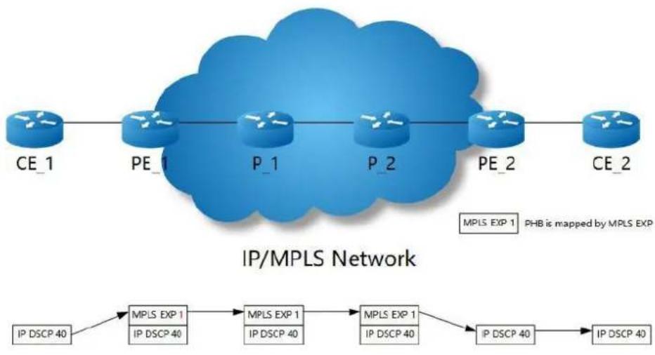
flowchart
graph TD
A["CE_1"] --> B["PE_1"]
B --> C["P_1"]
C --> D["P_2"]
D --> E["PE_2"]
E --> F["CE_2"]
G["MPLS EXP 1 PHB is mapped by MPLS EXP"] --> H["IP DSCP 40"]
H --> I["MPLS EXP 1"]
I --> J["IP DSCP 40"]
J --> K["MPLS EXP 1"]
K --> L["IP DSCP 40"]
L --> M["MPLS EXP 1"]
M --> N["IP DSCP 40"]
N --> O["MPLS EXP 1"]
O --> P["IP DSCP 40"]
Figure 18-6 Pipe model
Pipe model: On the ingress device, the packets will be added labels and the exp will be assigned by the users. On the egress device, the phb will be mapped from dscp and the output packetswill carry the original dscp.
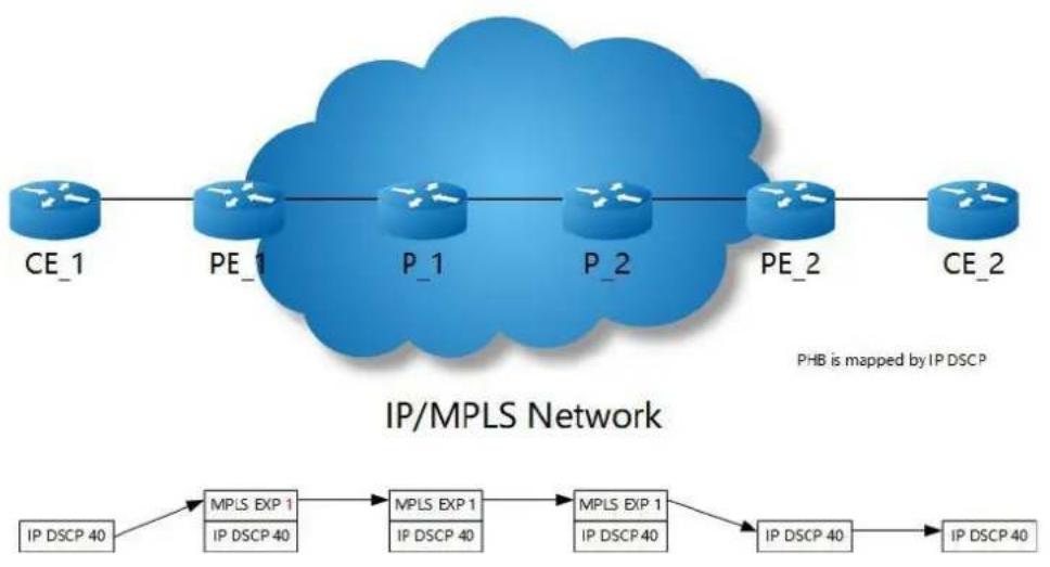
flowchart
graph TD
A["CE_1"] --> B["PE_1"]
B --> C["P_1"]
C --> D["P_2"]
D --> E["PE_2"]
E --> F["CE_2"]
G["IP DSCP 40"] --> H["MPLS EXP 1\nIP DSCP 40"] --> I["MPLS EXP 1\nIP DSCP 40"] --> J["MPLS EXP 1\nIP DSCP 40"] --> K["IP DSCP 40"] --> L["IP DSCP 40"]
style A fill:#f9f,stroke:#333
style B fill:#f9f,stroke:#333
style C fill:#f9f,stroke:#333
style D fill:#f9f,stroke:#333
style E fill:#f9f,stroke:#333
style F fill:#f9f,stroke:#333
style G fill:#ccf,stroke:#333
style H fill:#cfc,stroke:#333
style I fill:#cfc,stroke:#333
style J fill:#cfc,stroke:#333
style K fill:#cfc,stroke:#333
style L fill:#cfc,stroke:#333
Figure 18-7 Short pipe model
18.5.3 Configuration

flowchart
graph LR
PE1["PE1\neth-0-1"] -->|eth-0-9| P["P\neth-0-17"]
P -->|eth-0-17| PE2["PE2\neth-0-1"]
style PE1 fill:#4CAF50,stroke:#333
style P fill:#4CAF50,stroke:#333
style PE2 fill:#4CAF50,stroke:#333
Figure 18-8 MPLS QoS LSP model
MPLS QoS Uniform Configuration
The following example will describe how to configure MPLS QoS Uniform model.
The following configuration should be operated on all switches if the switch ID is not specified.
step 1 Enter the configure mode
Switch# configure terminal
step 2 Set MPLS LSP Model
Switch(config)#mpls lsp-model uniform
step 3 Enter the interface configure mode and set the attributes of the interface
Interface configuration for PE1:
Switch(config)# interface eth-0-9
Switch(config-if)# no switchport
Switch(config-if)# ip address 10.0.9.1/24
Switch(config-if)# label-switching
Switch(config-if)# exit
Switch(config)# interface eth-0-1
Switch(config-if)# no switchport
Switch(config-if)# qos domain type dscp 1
Switch(config-if)# trust dscp
Switch(config-if)# replace dscp
Switch(config-if)# ip address 1.1.1.1/24
Switch(config-if)# label-switching
Switch(config-if)# exit
Interface configuration for P:
Switch(config)# interface eth-0-9
Switch(config-if)# no switchport
Switch(config-if)# ip address 10.0.9.2/24
Switch(config-if)# label-switching
Switch(config-if)# exit
Switch(config)# interface eth-0-17
Switch(config-if)# no switchport
Switch(config-if)# ip address 10.0.17.2/24
Switch(config-if)# label-switching
Switch(config-if)# exit
Interface configuration for PE2:
Switch(config)# interface eth-0-17
Switch(config-if)# no switchport
Switch(config-if)# ip address 10.0.17.1/24
Switch(config-if)# label-switching
Switch(config-if)# exit
Switch(config)# interface eth-0-1
Switch(config-if)# no switchport
Switch(config-if)# qos domain type dscp 1
Switch(config-if)# trust dscp
Switch(config-if)# replace dscp
Switch(config-if)# ip address 2.2.2.2/24
Switch(config-if)# label-switching
Switch(config-if)# exit
step 4 Configure static arp
Interface configuration for PE1:
Switch(config)# arp 1.1.1.2 0001.0001.0002
Interface configuration for PE2:
Switch(config)# arp 2.2.2.1 0002.0002.0001
step 5 Configure static ftn/ilm
Static ftn for PE1:
Switch(config)# mpls ftn-entry 2.2.2.0/24 102 10.0.9.2
Switch(config)# mpls ilm-entry pop 201
Static ilm for P:
Switch(config)# mpls ilm-entry swap 102 10.0.17.1 203
Switch(config)# mpls ilm-entry swap 302 10.0.9.1 201
Static ilm for PE2:
Switch(config)# mpls ftn-entry 1.1.1.0/24 302 10.0.17.2
Switch(config)# mpls ilm-entry pop 203
step 6 Validation
Display the result on PE1:
PE1# show mpls ftn-database
Codes: > - selected FTN, p - stale FTN, B - BGP FTN, K - CLI FTN,
L - LDP FTN, R - RSVP-TE FTN, S - SNMP FTN, I - IGP-Shortcut,
* - bypass FTN, U - unknown FTN
Code FEC Out-Label Nexthop Out-Intf
K> 2.2.2.0/24 102 10.0.9.2 eth-0-9
PE1# show mpls ilm-database
Codes: > - selected ILM, * - LSP ILM, p - stale ILM, B - BGP ILM, K - CLI ILM,
L - LDP ILM, R - RSVP-TE ILM, S - SNMP ILM, I - IGP-Shortcut
U - unknown ILM
Code FEC I/O Label Nexthop Out-Intf
K> 0.0.0.0/0 201/- 0.0.0.0 N/A
Display the result on P:
P# show mpls ilm-database
Codes: > - selected ILM, * - LSP ILM, p - stale ILM, B - BGP ILM, K - CLI ILM,
L - LDP ILM, R - RSVP-TE ILM, S - SNMP ILM, I - IGP-Shortcut
U - unknown ILM
| Code | FEC | I/O Label | Nexthop | Out-Intf |
| K> | 0.0.0.0/0 | 102/203 | 10.0.17.1 | eth-0-17 |
| K> | 0.0.0.0/0 | 302/201 | 10.0.9.1 | eth-0-9 |
Display the result on PE2:
PE2# show mpls ftn-database
Codes: > - selected FTN, p - stale FTN, B - BGP FTN, K - CLI FTN,
L - LDP FTN, R - RSVP-TE FTN, S - SNMP FTN, I - IGP-Shortcut,
* - bypass FTN, U - unknown FTN
Code FEC Out-Label Nexthop Out-Intf
K> 1.1.1.0/24 302 10.0.17.2 eth-0-17
PE2# show mpls ilm-database
Codes: > - selected ILM, * - LSP ILM, p - stale ILM, B - BGP ILM, K - CLI ILM,
L - LDP ILM, R - RSVP-TE ILM, S - SNMP ILM, I - IGP-Shortcut
U - unknown ILM
Code FEC I/O Label Nexthop Out-Intf
K> 0.0.0.0/0 203/- 0.0.0.0 N/A
MPLS QoS Pipe Configuration
The following example will describe how to configure MPLS QoS Pipe model.
The following configuration should be operated on all switches if the switch ID is not specified.
step 1 Enter the configure mode
Switch# configure terminal
step 2 Set MPLS LSP Model
Interface configuration for PE1:
Switch(config)# mpls lsp-model pipe exp 7
Interface configuration for P:
Switch(config)#mpls lsp-model pipe
Interface configuration for PE2:
Switch(config)#mpls lsp-model pipe exp 7
step 3 Enter the interface configure mode and set the attributes of the interface
Interface configuration for PE1:
Switch(config)# interface eth-0-9
Switch(config-if)# no switchport
Switch(config-if)# ip address 10.0.9.1/24
Switch(config-if)# label-switching
Switch(config-if)# exit
Switch(config)# interface eth-0-1
Switch(config-if)# no switchport
Switch(config-if)# qos domain type dscp 1
Switch(config-if)# trust dscp
Switch(config-if)# ip address 1.1.1.1/24
Switch(config-if)# label-switching
Switch(config-if)# exit
Interface configuration for P:
Switch(config)# interface eth-0-9
Switch(config-if)# no switchport
Switch(config-if)# ip address 10.0.9.2/24
Switch(config-if)# label-switching
Switch(config-if)# exit
Switch(config)# interface eth-0-17
Switch(config-if)# no switchport
Switch(config-if)# ip address 10.0.17.2/24
Switch(config-if)# label-switching
Switch(config-if)# exit
Interface configuration for PE2:
Switch(config)# interface eth-0-17
Switch(config-if)# no switchport
Switch(config-if)# ip address 10.0.17.1/24
Switch(config-if)# label-switching
Switch(config-if)# exit
Switch(config)# interface eth-0-1
Switch(config-if)# no switchport
Switch(config-if)# qos domain type dscp 1
Switch(config-if)# trust dscp
Switch(config-if)# ip address 2.2.2.2/24
Switch(config-if)# label-switching
Switch(config-if)# exit
step 4 Configure static arp
Interface configuration for PE1:
Switch(config)# arp 1.1.1.2 0001.0001.0002
Interface configuration for PE2:
Switch(config)# arp 2.2.2.1 0002.0002.0001
step 5 Configure static ftn/ilm
Static ftn for PE1:
Switch(config)# mpls ftn-entry 2.2.2.0/24 102 10.0.9.2
Switch(config)# mpls ilm-entry pop 201
Static ilm for P:
Switch(config)#mpls ilm-entry swap 102 10.0.17.1 203
Switch(config)#mpls ilm-entry swap 302 10.0.9.1 201
Static ilm for PE2:
Switch(config)# mpls ftn-entry 1.1.1.0/24 302 10.0.17.2
Switch(config)# mpls ilm-entry pop 203
step 6 Validation
Display the result on PE1:
PE1# show mpls ftn-database
Codes: > - selected FTN, p - stale FTN, B - BGP FTN, K - CLI FTN,
L - LDP FTN, R - RSVP-TE FTN, S - SNMP FTN, I - IGP-Shortcut,
* - bypass FTN, U - unknown FTN
Code FEC Out-Label Nexthop Out-Intf
K> 2.2.2.0/24 102 10.0.9.2 eth-0-9
PE1# show mpls ilm-database
Codes: > - selected ILM, * - LSP ILM, p - stale ILM, B - BGP ILM, K - CLI ILM,
L - LDP ILM, R - RSVP-TE ILM, S - SNMP ILM, I - IGP-Shortcut
U - unknown ILM
Code FEC I/O Label Nexthop Out-Intf
K> 0.0.0.0/0 201/- 0.0.0.0 N/A
Display the result on P:
P# show mpls ilm-database
Codes: > - selected ILM, * - LSP ILM, p - stale ILM, B - BGP ILM, K - CLI ILM,
L - LDP ILM, R - RSVP-TE ILM, S - SNMP ILM, I - IGP-Shortcut
U - unknown ILM
Code FEC I/O Label Nexthop Out-Intf
K> 0.0.0.0/0 102/203 10.0.17.1 eth-0-17
K> 0.0.0.0/0 302/201 10.0.9.1 eth-0-9
Display the result on PE2:
PE2# show mpls ftn-database
Codes: > - selected FTN, p - stale FTN, B - BGP FTN, K - CLI FTN,
L - LDP FTN, R - RSVP-TE FTN, S - SNMP FTN, I - IGP-Shortcut,
* - bypass FTN, U - unknown FTN
Code FEC Out-Label Nexthop Out-Intf
K> 1.1.1.0/24 302 10.0.17.2 eth-0-17
PE2# show mpls ilm-database
Codes: > - selected ILM, * - LSP ILM, p - stale ILM, B - BGP ILM, K - CLI ILM,
L - LDP ILM, R - RSVP-TE ILM, S - SNMP ILM, I - IGP-Shortcut
U - unknown ILM
Code FEC I/O Label Nexthop Out-Intf
K> 0.0.0.0/0 203/- 0.0.0.0 N/A
MPLS QoS Short Pipe Configuration
The following example will describe how to configure MPLS QoS Short Pipe model.
The following configuration should be operated on all switches if the switch ID is not specified.
step 1 Enter the configure mode
Switch# configure terminal
step 2 Set MPLS LSP Model
Interface configuration for PE1:
Switch(config)# mpls lsp-model short-pipe exp 7
Interface configuration for P:
Switch(config)#mpls lsp-model short-pipe
Interface configuration for PE2:
Switch(config)# mpls lsp-model short-pipe exp 7
step 3 Enter the interface configure mode and set the attributes of the interface
Interface configuration for PE1:
Switch(config)# interface eth-0-9
Switch(config-if)# no switchport
Switch(config-if)# ip address 10.0.9.1/24
Switch(config-if)# label-switching
Switch(config-if)# exit
Switch(config)# interface eth-0-1
Switch(config-if)# no switchport
Switch(config-if)# qos domain type dscp 1
Switch(config-if)# trust dscp
Switch(config-if)# ip address 1.1.1.1/24
Switch(config-if)# label-switching
Switch(config-if)# exit
Interface configuration for P:
Switch(config)# interface eth-0-9
Switch(config-if)# no switchport
Switch(config-if)# ip address 10.0.9.2/24
Switch(config-if)# label-switching
Switch(config-if)# exit
Switch(config)# interface eth-0-17
Switch(config-if)# no switchport
Switch(config-if)# ip address 10.0.17.2/24
Switch(config-if)# label-switching
Switch(config-if)# exit
Interface configuration for PE2:
Switch(config)# interface eth-0-17
Switch(config-if)# no switchport
Switch(config-if)# ip address 10.0.17.1/24
Switch(config-if)# label-switching
Switch(config-if)# exit
Switch(config)# interface eth-0-1
Switch(config-if)# no switchport
Switch(config-if)# qos domain type dscp 1
Switch(config-if)# trust dscp
Switch(config-if)# ip address 2.2.2.2/24
Switch(config-if)# label-switching
Switch(config-if)# exit
step 4 Configure static arp
Interface configuration for PE1:
Switch(config)# arp 1.1.1.2 0001.0001.0002
Interface configuration for PE2:
Switch(config)# arp 2.2.2.1 0002.0002.0001
step 5 Configure static ftn/ilm
Static ftn for PE1:
Switch(config)# mpls ftn-entry 2.2.2.0/24 102 10.0.9.2
Switch(config)# mpls ilm-entry pop 201
Static ilm for P:
Switch(config)# mpls ilm-entry swap 102 10.0.17.1 203
Switch(config)# mpls ilm-entry swap 302 10.0.9.1 201
Static ilm for PE2:
Switch(config)# mpls ftn-entry 1.1.1.0/24 302 10.0.17.2
Switch(config)# mpls ilm-entry pop 203
step 6 Validation
Display the result on PE1:
PE1# show mpls ftn-database
Codes: > - selected FTN, p - stale FTN, B - BGP FTN, K - CLI FTN,
L - LDP FTN, R - RSVP-TE FTN, S - SNMP FTN, I - IGP-Shortcut,
* - bypass FTN, U - unknown FTN
Code FEC Out-Label Nexthop Out-Intf
K> 2.2.2.0/24 102 10.0.9.2 eth-0-9
PE1# show mpls ilm-database
Codes: > - selected ILM, * - LSP ILM, p - stale ILM, B - BGP ILM, K - CLI ILM,
L - LDP ILM, R - RSVP-TE ILM, S - SNMP ILM, I - IGP-Shortcut
U - unknown ILM
Code FEC I/O Label Nexthop Out-Intf
K> 0.0.0.0/0 201/- 0.0.0.0 N/A
Display the result on P:
P# show mpls ilm-database
Codes: > - selected ILM, * - LSP ILM, p - stale ILM, B - BGP ILM, K - CLI ILM,
L - LDP ILM, R - RSVP-TE ILM, S - SNMP ILM, I - IGP-Shortcut
U - unknown ILM
Code FEC I/O Label Nexthop Out-Intf
K> 0.0.0.0/0 102/203 10.0.17.1 eth-0-17
K> 0.0.0.0/0 302/201 10.0.9.1 eth-0-9
Display the result on PE2:
PE2# show mpls ftn-database
Codes: > - selected FTN, p - stale FTN, B - BGP FTN, K - CLI FTN,
L - LDP FTN, R - RSVP-TE FTN, S - SNMP FTN, I - IGP-Shortcut,
* - bypass FTN, U - unknown FTN
Code FEC Out-Label Nexthop Out-Intf
K> 1.1.1.0/24 302 10.0.17.2 eth-0-17
PE2# show mpls ilm-database
Codes: > - selected ILM, * - LSP ILM, p - stale ILM, B - BGP ILM, K - CLI ILM,
L - LDP ILM, R - RSVP-TE ILM, S - SNMP ILM, I - IGP-Shortcut
U - unknown ILM
Code FEC I/O Label Nexthop Out-Intf
K> 0.0.0.0/0 203/- 0.0.0.0 N/A
18.5.4 Application cases
N/A
18.6 Configuring L3VPN
18.6.1 Overview
Function Introduction
This chapter describes how to configure L3VPN. It uses Route Target's community to control route sending and receiving. RD is used to distinguish which VPN the route from. The inner label is uesd to map the different vrf, then through the vrf to guide packet forwarding.
Principle Description
N/A
18.6.2 Configuration
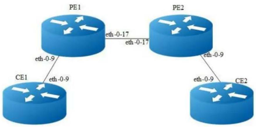
flowchart
graph TD
PE1["PE1"] -->|eth-0-9| CE1["CE1"]
PE1 -->|eth-0-17| PE2["PE2"]
PE2 -->|eth-0-9| CE2["CE2"]
CE1 -->|eth-0-9| PE1
PE2 -->|eth-0-17| PE1
Figure 18-9 L3VPN Model
Configuring L3VPN
The following example will describe how to configure L3VPN:
The following configuration should be operated on all switches if the switch ID is not specified.
step 1 Enter the configure mode
Switch# configure terminal
step 2 Set vrf
Vrf configuration for PE1:
Switch(config)# ip vrf vpn1
Switch(config-vrf)# rd 1:1
Switch(config-vrf)# route-target both 1:1
Switch(config-vrf)# exit
Vrf configuration for PE2:
Switch(config)# ip vrf vpn1
Switch(config-vrf)# rd 1:1
Switch(config-vrf)# route-target both 1:1
Switch(config-vrf)# exit
step 3 Enter the interface configure mode and set the attributes of the interface
Interface configuration for CE1:
Switch(config)# interface eth-0-9
Switch(config-if)# no switchport
Switch(config-if)# ip address 2.2.2.1/24
Switch(config-if)# exit
Switch(config)# interface loopback 0
Switch(config-if)# ip address 4.4.4.4/32
Switch(config-if)# exit
Interface configuration for PE1, eth-0-9 need enable ldp and join vrf:
Switch(config)# interface eth-0-9
Switch(config-if)# no switchport
Switch(config-if)# ip vrf forwarding vpn1
Switch(config-if)# ip address 2.2.2.2/24
Switch(config-if)# exit
Switch(config)# interface eth-0-17
Switch(config-if)# no switchport
Switch(config-if)# label-switching
Switch(config-if)# ip address 1.1.1.1/24
Switch(config-if)# enable-ldp
Switch(config-if)# exit
Switch(config)# interface loopback 0
Switch(config-if)# ip address 5.5.5.5/32
Switch(config-if)# exit
Interface configuration for PE2, eth-0-9 need enable ldp and join vrf:
Switch(config)# interface eth-0-9
Switch(config-if)# no switchport
Switch(config-if)# ip vrf forwarding vpn1
Switch(config-if)# ip address 3.3.3.3/24
Switch(config-if)# exit
Switch(config)# interface eth-0-17
Switch(config-if)# no switchport
Switch(config-if)# label-switching
Switch(config-if)# ip address 1.1.1.2/24
Switch(config-if)# enable-ldp
Switch(config-if)# exit
Switch(config)# interface loopback 0
Switch(config-if)# ip address 6.6.6.6/32
Switch(config-if)# exit
Interface configuration for CE2:
Switch(config)# interface eth-0-9
Switch(config-if)# no switchport
Switch(config-if)# ip address 3.3.3.4/24
Switch(config-if)# exit
Switch(config)# interface loopback0
Switch(config-if)# ip address 7.7.7.7/32
Switch(config-if)# exit
step 4 Enable router ldp
LDP configuration for PE1:
Switch(config)# router ldp
Switch(config-router)# router-id 5.5.5.5
Switch(config-router)# exit
LDP configuration for PE2:
Switch(config)# router ldp
Switch(config-router)# router-id 6.6.6.6
Switch(config-router)# exit
step 5 Enable router rip
RIP configuration for CE1:
Switch(config)# router rip
Switch(config-router)# network 2.2.2.2/24
Switch(config-router)# redistribute connected
Switch(config-router)# exit
RIP configuration for PE1:
Switch(config)# router rip
Switch(config-router)# address-family ipv4 vrf vpn1
Switch(config-router-af)# network 2.2.2.0/24
Switch(config-router-af)# redistribute bgp
Switch(config-router-af)# exit-address-family
Switch(config-router)# exit
RIP configuration for PE2:
Switch(config)# router rip
Switch(config-router)# address-family ipv4 vrf vpn1
Switch(config-router-af)# network 3.3.3.3/24
Switch(config-router-af)# redistribute bgp
Switch(config-router-af)# exit-address-family
Switch(config-router)# exit
RIP configuration for CE2:
Switch(config)# router rip
Switch(config-router)# network 3.3.3.0/24
Switch(config-router)# redistribute connected
Switch(config-router)# exit
step 6 Enable router ospf
OSPF configuration for PE1:
Switch(config)#router ospf
Switch(config-router)# redistribute connected
Switch(config-router)# network 1.1.1.0/24 area 0
Switch(config-router)# exit
OSPF configuration for PE2:
Switch(config)# router ospf
Switch(config-router)# redistribute connected
Switch(config-router)# network 1.1.1.0/24 area 0
Switch(config-router)# exit
step 7 Enable router bgp
BGP configuration for PE1:
Switch(config)# router bgp 1
Switch(config-router)# neighbor 6.6.6.6 remote-as 1
Switch(config-router)# neighbor 6.6.6.6 update-source loopback0
Switch(config-router)# address-family ipv4
Switch(config-router-af)# no synchronization
Switch(config-router-af)# neighbor 6.6.6.6 activate
Switch(config-router-af)# exit-address-family
Switch(config-router)# address-family vpnv4 unicast
Switch(config-router-af)# no synchronization
Switch(config-router-af)# neighbor 6.6.6.6 activate
Switch(config-router-af)# neighbor 6.6.6.6 send-community both
Switch(config-router-af)# exit-address-family
Switch(config-router)# address-family ipv4 vrf vpn1
Switch(config-router-af)# redistribute connected
Switch(config-router-af)# redistribute rip
Switch(config-router-af)# no synchronization
Switch(config-router-af)# exit-address-family
Switch(config-router)# exit
BGP configuration for PE2:
Switch(config)# router bgp 1
Switch(config-router)# neighbor 5.5.5.5 remote-as 1
Switch(config-router)# neighbor 5.5.5.5 update-source loopback0
Switch(config-router)# address-family ipv4
Switch(config-router-af)# no synchronization
Switch(config-router-af)# neighbor 5.5.5.5 activate
Switch(config-router-af)# exit-address-family
Switch(config-router)# address-family vpnv4 unicast
Switch(config-router-af)# no synchronization
Switch(config-router-af)# neighbor 5.5.5.5 activate
Switch(config-router-af)# neighbor 5.5.5.5 send-community both
Switch(config-router-af)# exit-address-family
Switch(config-router)# address-family ipv4 vrf vpn1
Switch(config-router-af)# redistribute connected
Switch(config-router-af)# redistribute rip
Switch(config-router-af)# no synchronization
Switch(config-router-af)# exit-address-family
Switch(config-router)# exit
step 8 Validation
Use show ip route command and ping CE2 loopback address to validate the l3vpn is worked.
Display the result on PE1:
PE1# show ip route
s: K - kernel, C - connected, S - static, R - RIP, B - BGP
O - OSPF, IA - OSPF inter area
N1 - OSPF NSSA external type 1, N2 - OSPF NSSA external type 2
E1 - OSPF external type 1, E2 - OSPF external type 2
i - IS-IS, L1 - IS-IS level-1, L2 - IS-IS level-2, ia - IS-IS inter area
Dc - DHCP Client
[*] - [AD/Metric]
* - candidate default
C 2.2.2.0/24 is directly connected, eth-0-9
C 2.2.2.1/32 is in local loopback, eth-0-9
R 3.3.3.0/24 [120/2] via 2.2.2.2, eth-0-9, 00:00:04
C 4.4.4.4/32 is directly connected, loopback0
R 7.7.7.7/32 [120/2] via 2.2.2.2, eth-0-9, 00:00:02
PE1# ping 7.7.7.7
PING 7.7.7.7 (7.7.7.7) 56(84) bytes of data.
64 bytes from 7.7.7.7: icmp_seq=0 ttl=62 time=1828 ms
64 bytes from 7.7.7.7: icmp_seq=1 ttl=62 time=1801 ms
64 bytes from 7.7.7.7: icmp_seq=2 ttl=62 time=1775 ms
64 bytes from 7.7.7.7: icmp_seq=3 ttl=62 time=1775 ms
64 bytes from 7.7.7.7: icmp_seq=4 ttl=62 time=1705 ms
--- 7.7.7.7 ping statistics ---
5 packets transmitted, 5 received, 0% packet loss, time 4018ms
rtt min/avg/max/mdev = 1705.600/1777.267/1828.148/40.840 ms, pipe 3
18.6.3 Application cases
N/A
19 PoE
19.1 PoE Overview
PoE (Power over Ethernet, remote power supply): It is a mechanism for supplying power to a PD (Powered Device) connected remotely through the Ethernet to realize parallel power supply and data transmission. Common PD devices include IP phones, wireless APs, IP cameras, and various new IoT terminal devices. PoE technology is widely used for its characteristics of centralized power supply, centralized management, convenient installation, and unified software and hardware standards.
PoE system involves the following devices:
PSE (Power-Sourcing Equipment): A PSE is a PoE device that provides power to PDs and supports detection, analysis, and intelligent power management.
PD (Power Device): A PD is a device that receives power from a PSE.PDs are classified into standard and non-standard PDs depending on whether they conform to IEEE standards: 802.3af, 802.3at, 802.3bt.
PoE power supply : A PoE power supply provides power to a PoE system. The number of PDs connected to a PSE is limited by the power output of the PoE power supply.
19.2 features and configurations
19.2.1 Configuring Global PoE power management scheme
Configure the switch power management scheme in global configuration mode, including the power limit mode and power policy for PoE ports.
limit-mode: Power limit mode. The port power can be allocated based on the PD class automatically detected by the PoE port, or the port power can be allocated
according to the max-power parameter configured by the user on the port. The port allocation power values corresponding to different categories are as follows:
| class | power limit (W) |
| 1 | 4 |
| 2 | 7 |
| 3 | 15.4 |
| 4 | 30 |
| 5 | 45 |
| 6 | 60 |
| 7 | 75 |
| 8 | 90 |
policy: Power allocation policy. There are two strategies: dynamic and static. When configured as dynamic, the remaining available power is calculated from the total PoE power allocable power minus the actual power allocated by all ports. Then decide whether to supply power to the newly connected PD according to the remaining available power and the current power consumption of the newly connected PD; when the configuration is static, the system calculates the maximum power supply power of each port in use according to limit-mode and reserves power for it. Then, it is determined whether to supply power to the newly connected PD according to the remaining available power and the current power consumption of the newly connected PD.
Autoclass: When configuring the static power allocation policy, you can choose whether to enable the autoclass function. If autoclass is enabled and the PD also supports the autoclass function, the power can be reserved for the port more reasonably through the negotiation between the PSE and the PD, so as to avoid the waste of reserving too much power for low-power loads, and rational use of resources can be used in more supply power to the PD on the interface.
| SwitchA# configure terminal | Enter configuration mode |
| Switch(config)# poe power-management limit-mode class | Configure the power limit mode of each interface to use the class-based power limit mode. |
| Switch(config)# poe power-management policy static autoclass enable | Configure the power management policy as static and enable the autoclass function. If the PD supports this function, it is more reasonable to reserve power. |
For example, the power limit mode in the three PoE configurations is also "based on port's configured max power". However, when the "power policy" is dynamic, static, and static, the auto class function is enabled at the same time. When comparing the "granted power", "power limit", and "available power" in the "PoE status" and "PoE summary" in the above three configurations, you can more intuitively see the difference in power distribution results. The following are examples of configuration and status display:
Switch# configure terminal
Switch(config)# poe power-management limit-mode class
Switch(config)# end
Switch# show poe status
Codes : IF - interface CH - channel ST - enable status
MD - mode CL - class PR - priority
V - voltage(V) mA - current(mA) TP - temperature('C)
GT - granted power(W) LM - power limit(W) CS - consumption(W)
AP - available power(W)
DIS - disable EN - enable
CR - critical HI - high LO - low
OP - operation status of poe
IF ST OP MD CL PR V mA TP GT LM CS AP
eth-0-1 EN OFF POE_BT -- LO 0.0 0 36 0.000 -- 0.000 --
eth-0-2 EN OFF POE_BT -- LO 0.0 0 36 0.000 -- 0.000 --
eth-0-3 EN OFF POE_BT -- LO 0.0 0 36 0.000 -- 0.000 --
eth-0-4 EN OFF POE_BT -- LO 0.0 0 36 0.000 -- 0.000 --
eth-0-5 EN OFF POE_BT -- LO 0.0 0 36 0.000 -- 0.000 --
eth-0-6 EN OFF POE_BT -- LO 0.0 0 37 0.000 -- 0.000 --
eth-0-7 EN OFF POE_BT -- LO 0.0 0 37 0.000 -- 0.000 --
eth-0-8 EN OFF POE_BT -- LO 0.0 0 37 0.000 -- 0.000 --
eth-0-9 EN ON POE_BT 8 LO 54.6 679 37 37.254 41.000 37.055 3.945
eth-0-10 EN OFF POE_BT -- LO 0.0 0 39 0.000 -- 0.000 --
eth-0-11 EN OFF POE_BT -- LO 0.0 0 39 0.000 -- 0.000 --
eth-0-12 EN OFF POE_BT -- LO 0.0 0 39 0.000 -- 0.000 --
eth-0-13 EN ON POE_BT 6 LO 54.7 34 39 1.639 60.000 1.858 58.142
eth-0-14 EN OFF POE_BT -- LO 0.0 0 41 0.000 -- 0.000 --
eth-0-15 EN OFF POE_BT -- LO 0.0 0 41 0.000 -- 0.000 --
eth-0-16 EN OFF POE_BT -- LO 0.0 0 41 0.000 -- 0.000 --
eth-0-17 EN OFF POE_BT -- LO 0.0 0 41 0.000 -- 0.000 --
eth-0-18 EN OFF POE_BT -- LO 0.0 0 43 0.000 -- 0.000 --
eth-0-19 EN ON POE_BT 4 LO 54.5 33 43 1.797 30.000 1.797 28.203
eth-0-20 EN OFF POE_BT -- LO 0.0 0 43 0.000 -- 0.000 --
eth-0-21 EN OFF POE_BT -- LO 0.0 0 43 0.0O O -- O.O.O O --
eth-0-22 EN OFF POE_BT -- LO 1. O.O O O - - O.O.O O --
eth-0-23 EN OFF POE_BT -- LO O.O O O - - O.O.O O --
eth-0-24<fcel>EN + + + + + + + + + + + + + + + + + + + + + + + + + + + + + + + + + + + + + + + + + + + + + + + + + + + + + + + + + + + + + + + + + + + + + + + + + + + + + + + + + + + + + + + + + + + + + + + + + + + +
Switch# show poe summary
Power Source Equipment NO: 1
Operation status: enable
Channel Num for power: 48
PSE Firmware Version: Ve0.17.36.01
PSE SRAM Patch Version: 0x0
PSE PSU Information
PSU1: Absent
PSU2: 400 W Present
PSE Power Policy: Dynamic
PSE Power Limit Mode: Class Based Limit
PSE Legacy PD Enable: Disable
Power Limit: 400000 mW
Power Available: 359094 mW
Power Actual Consump: 40483 mW
Power Allocated: 40906 mW
Power Reserved: 30000 mW
Power Threshold: 90%
PSE Reserved Power Alert: -
PSE Threshold Power Alert: -
PSE Device Temperature
Device 0: 39 degC
Device 1: 39 degC
Device 2: 41 degC
Device 3: 39 degC
Device 4: 40 degC
Device 5: 42 degC
PSE Device Faults
SRAM Fault: -
TSD Fault: -
VPWR Fault: -
VDD Fault: -
Switch#
Switch# configure terminal
Switch(config)# poe power-management policy dynamic
Switch(config)# end
Switch# show poe status
Codes : IF - interface CH - channel ST - enable status
MD - mode CL - class PR - priority
V - voltage(V) mA - current(mA) TP - temperature('C)
GT - granted power(W) LM - power limit(W) CS - consumption(W)
AP - available power(W)
DIS - disable EN - enable
CR - critical HI - high LO - low
OP - operation status of poe
| IF | ST | OP | MD | CL | PR | V | mA | TP | GT | LM | CS | AP |
| eth-0-1 | EN | OFF | POE_BT | -- | LO | 0.0 | 0 | 36 | 0.000 | -- | 0.000 | -- |
| eth-0-2 | EN | OFF | POE_BT | -- | LO | 0.0 | 0 | 36 | 0.000 | -- | 0.000 | -- |
| eth-0-3 | EN | OFF | POE_BT | -- | LO | 0.0 | 0 | 36 | 0.000 | -- | 0.000 | -- |
| eth-0-4 | EN | OFF | POE_BT | -- | LO | 0.0 | 0 | 36 | 0.000 | -- | 0.000 | -- |
| eth-0-5 | EN | OFF | POE_BT | -- | LO | 0.0 | 0 | 36 | 0.000 | -- | 0.000 | -- |
| eth-0-6 | EN | OFF | POE_BT | -- | LO | 0.0 | 0 | 39 | 0.000 | -- | 0.000 | -- |
| eth-0-7 | EN | OFF | POE_BT | -- | LO | 0.0 | 0 | 39 | 0.000 | -- | 0.000 | -- |
| eth-0-8 | EN | OFF | POE_BT | -- | LO | 0.0 | 0 | 39 | 0.000 | -- | 0.000 | -- |
| eth-0-9 | EN | ON | POE_BT | 8 | LO | 54.9 | 679 | 39 | 37.099 | 41.000 | 37.267 | 3.733 |
| eth-0-10 | EN | OFF | POE_BT | -- | LO | 0.0 | 0 | 39 | 0.000 | -- | 0.000 | -- |
| eth-0-11 | EN | OFF | POE_BT | -- | LO | 0.0 | 0 | 39 | 0.000 | -- | 0.000 | -- |
| eth-0-12 | EN | OFF | POE_BT | -- | LO | 0.0 | 0 | 39 | 0.000 | -- | 0.000 | -- |
eth-0-13 EN ON POE_BT 6 LO 54.7 34 39 1.847 90.000 1.858 88.142
eth-0-14 EN OFF POE_BT -- LO 0.0 0 39 0.000 -- 0.000 --
eth-0-15 EN OFF POE_BT -- LO 0.0 0 39 0.000 -- 0.000 --
eth-0-16 EN OFF POE_BT -- LO 0.0 0 39 0.000 -- 0.000 --
eth-0-17 EN OFF POE_BT -- LO 0.0 0 39 0.000 -- 0.000 --
eth-0-18 EN OFF POE_BT -- LO 0.0 0 42 0.000 -- 0.000 --
eth-0-19 EN ON POE_BT 4 LO 54.5 34 42 1.797 75.000 1.852 73.148
eth-0-20 EN OFF POE_BT -- LO 0.0 0 42 0.000 -- 0.000 --
eth-0-21 EN OFF POE_BT -- LO 0.0 0 42 0.000 -- 0.000 --
eth-0-22 EN OFF POE_BT -- LO 0.0 0 40 0.000 -- 0.000 --
eth-0-23 EN OFF POE_BT -- LO 0.0 0 40 0.000 -- 0.000 --
eth-0-24 EN OFF POE_BT -- LO 0.0 0 40 0.000 -- 0.000 --
Switch# show poe summary
Power Source Equipment NO: 1
Operation status: enable
Channel Num for power: 48
PSE Firmware Version: Ve0.17.36.01
PSE SRAM Patch Version: 0x0
PSE PSU Information
PSU1: Absent
PSU2: 400 W Present
PSE Power Policy: Dynamic
PSE Power Limit Mode: Port Based Limit
PSE Legacy PD Enable: Disable
Power Limit: 400000 mW
Power Available: 359186 mW
Power Actual Consump: 40977 mW
Power Allocated: 40814 mW
Power Reserved: 30000 mW
Power Threshold: 90%
PSE Reserved Power Alert: -
PSE Threshold Power Alert: -
PSE Device Temperature
Device 0: 36 degC
Device 1: 36 degC
Device 2: 39 degC
Device 3: 39 degC
Device 4: 39 degC
Device 5: 42 degC
PSE Device Faults
SRAM Fault: -
TSD Fault: -
VPWR Fault: -
VDD Fault: -
Switch#
Switch# configure terminal
Switch(config)# poe power-management limit-mode port
Switch(config)# poe power-management policy static autoclass enable
Switch(config)# end
Switch# show poe status
Codes : IF - interface CH - channel ST - enable status
MD - mode CL - class PR - priority
V - voltage(V) mA - current(mA) TP - temperature('C)
GT - granted power(W) LM - power limit(W) CS - consumption(W)
AP - available power(W)
DIS - disable EN - enable
CR - critical HI - high LO - low
OP - operation status of poe
+
| IF | ST | OP | MD | CL | PR | V | mA | TP | GT | LM | CS | AP |
| eth-0-1 | EN | OFF | POE_BT | -- | LO | 0.0 | 0 | 36 | 0.000 | -- | 0.000 | -- |
| eth-0-2 | EN | OFF | POE_BT | -- | LO | 0.0 | 0 | 36 | 0.000 | -- | 0.000 | -- |
| eth-0-3 | EN | OFF | POE_BT | -- | LO | 0.0 | 0 | 36 | 0.000 | -- | 0.000 | -- |
| eth-0-4 | EN | OFF | POE_BT | -- | LO | 0.0 | 0 | 36 | 0.000 | -- | 0.000 | -- |
| eth-0-5 | EN | OFF | POE_BT | -- | LO | 0.0 | 0 | 36 | 0.000 | -- | 0.000 | -- |
| eth-0-6 | EN | OFF | POE_BT | -- | LO | 0.0 | 0 | 39 | 0.000 | -- | 0.000 | -- |
| eth-0-7 | EN | OFF | POE_BT | -- | LO | 0.0 | 0 | 39 | 0.000 | -- | 0.000 | -- |
| eth-0-8 | EN | OFF | POE_BT | -- | LO | 0.0 | 0 | 39 | 0.000 | -- | 0.000 | -- |
| eth-0-9 | EN | ON | POE_BT 8 | LO | 54.6 | 679 | 39 | 38.000 | 41.000 | 37.053 | 3.947 | |
| eth-0-10 | EN | OFF | POE_BT | -- | LO | 0.0 | 0 | 39 | 0.000 | -- | 0.000 | -- |
| eth-0-11 | EN | OFF | POE_BT | -- | LO | 0.0 | 0 | 39 | 0.000 | -- | 0.000 | -- |
| eth-0-12 | EN | OFF | POE_BT | -- | LO | 0.0 | 0 | 39 | 0.000 | -- | 0.000 | -- |
| eth-0-13 | EN | ON | POE_BT 6 | LO | 54.4 | 34 | 39 | 90.000 | 90.000 | 1.847 | 88.153 | |
| eth-0-14 | EN | OFF | POE_BT | -- | LO | 0.0 | 0 | 41 | 0.000 | -- | 0.000 | -- |
| eth-0-15 | EN | OFF | POE_BT | -- | LO | 0.0 | 0 | 41 | 0.000 | -- | 0.000 | -- |
| eth-0-16 | EN | OFF | POE_BT | -- | LO | 0.0 | 0 | 41 | 0.000 | -- | 0.000 | -- |
| eth-0-17 | EN | OFF | POE_BT | -- | LO | 0.0 | 0 | 41 | 0.000 | -- | 0.000 | -- |
| eth-0-18 | EN | OFF | POE_BT | -- | LO | 0.0 | 0 | 42 | 0.000 | -- | 0.000 | -- |
| eth-0-19 | EN | ON | POE_BT 4 | LO | 54.5 | 33 | 42 | 75.000 | 75.000 | 1.798 | 73.202 | |
| eth-0-20 | EN | OFF | POE_BT | -- | LO | 0.0 | 0 | 42 | 0.000 | -- | 0.000 | -- |
| eth-0-21 | EN | OFF | POE_BT | -- | LO | 0.0 | 0 | 42 | 0.000 | -- | 0.000 | -- |
| eth-0-22 | EN | OFF | POE_BT | -- | LO | 0.0 | 0 | 41 | 0.000 | -- | 0.000 | -- |
| eth-0-23 | EN | OFF | POE_BT | -- | LO | 0.0 | 0 | 41 | 0.000 | -- | 0.000 | -- |
| eth-0-24 | EN | OFF | POE_BT | -- | LO | 0.0 | 0 | 41 | 0.000 | -- | 0.000 | -- |
Switch# show poe summary
Power Source Equipment NO: 1
Operation status: enable
Channel Num for power: 48
PSE Firmware Version: Ve0.17.36.01
PSE SRAM Patch Version: 0x0
PSE PSU Information
PSU1: Absent
PSU2: 400 W Present
PSE Power Policy: Static w/ Autoclass
PSE Power Limit Mode: Port Based Limit
PSE Legacy PD Enable: Disable
Power Limit: 400000 mW
Power Available: 197000 mW
Power Actual Consump: 40907 mW
Power Allocated: 203000 mW
Power Reserved: 30000 mW
Power Threshold: 90%
PSE Reserved Power Alert: -
PSE Threshold Power Alert: -
PSE Device Temperature
Device 0:35 degC
Device 1: 35 degC
Device 2: 39 degC
Device 3: 39 degC
Device 4: 40 degC
Device 5: 43 degC
PSE Device Faults
SRAM Fault: -
TSD Fault: -
VPWR Fault: -
VDD Fault: -
Switch# configure terminal
Switch(config)# poe power-management policy static autoclass disable
Switch(config)# end
Switch# show poe status
Codes : IF - interface CH - channel ST - enable status
MD - mode CL - class PR - priority
V - voltage(V) mA - current(mA) TP - temperature('C)
GT - granted power(W) LM - power limit(W) CS - consumption(W)
AP - available power(W)
DIS - disable EN - enable
CR - critical HI - high LO - low
OP - operation status of poe
+----+ + + + + + + + + + + +
IF ST OP MD CL PR V mA TP GT LM CS AP
eth-0-1 EN OFF POE_BT -- LO 0.0 0 34 0.000 -- 0.000 --
eth-0-2 EN OFF POE_BT -- LO 0.0 0 34 0.000 -- 0.000 --
eth-0-3 EN OFF POE_BT -- LO 0.0 0 34 0.000 -- 0.000 --
cth-0-4 EN OFF POE_BT -- LO 0.0 0 34 0.000 -- 0.000 --
eth-0-5 EN OFF POE_BT -- LO 0.0 0 34 0.000 -- 0.000 --
eth-0-6 EN OFF POE_BT -- LO 0.0 0 39 0.000 -- 0.000 --
eth-0-7 EN OFF POE_BT -- LO 0.0 0 39 0.000 -- 0.000 --
eth-0-8 EN OFF POE_BT -- LO 0.0 0 39 0.000 -- 0.000 --
eth-0-9 EN ON POE_BT 8 LO 54.9 679 39 90.000 41.000 37.259 3.741
eth-0-10 EN OFF POE_BT -- LO 0.0 0 39 0.000 -- 0.000 --
eth-0-11 EN OFF POE_BT -- LO 0.0 0 39 0.000 -- 0.000 --
eth-0-12 EN OFF POE_BT -- LO 0.0 0 39 0.000 -- 0.000 --
cth-0-13 EN ON POE_BT 6 LO 54.4 34 39 90.000 90.000 1.847 88.153
eth-0-14 EN OFF POE_BT -- LO 0.0 0 40 0.000 -- 0.000 --
eth-0-15 EN OFF POE_BT -- LO 0.0 0 40 0.000 -- 0.000 --
eth-0-16 EN OFF POE_BT -- LO 0.0 0 40 0.000 -- 0.000 --
eth-0-17 EN OFF POE_BT -- LO 0.0 0 42 75.00<fcel>-- -- -- -- -- -- -- -- -- -- -- -- -- -- -- -- -- -- -- -- -- -- -- -- -- -- -- -- -- -- -- -- -- -- -- -- -- -- -- -- -- -- -- -- -- -- -- -- -- -- -- |
eth-0-18 EN ON POE_BT -- LO 54.5 33 42 75.0<fcel>-- | | | | | | | | | | | | | | | | | | | | | | | | | | | | | | | | | | | | | | | | | | | | | | | | | | | | | | | | | | | | | | | | | | | | | | | | | | | | | | | | | | | | | | | | | | | | | | | | | | | | |
Switch# show poe summary
Power Source Equipment NO: 1
Operation status: enable
Channel Num for power: 48
PSE Firmware Version: Ve0.17.36.01
PSE SRAM Patch Version: 0x0
PSE PSU Information
PSU1: Absent
PSU2: 400 W Present
PSE Power Policy: Static w/o Autoclass
PSE Power Limit Mode: Port Based Limit
PSE Legacy PD Enable: Disable
Power Limit: 400000 mW
Power Available: 145000 mW
Power Actual Consump: 40903 mW
Power Allocated: 255000 mW
Power Reserved: 30000 mW
Power Threshold: 90%
PSE Reserved Power Alert: -
PSE Threshold Power Alert: -
PSE Device Temperature
Device 0: 36 degC
Device 1: 36 degC
Device 2: 39 degC
Device 3: 39 degC
Device 4: 41 degC
Device 5: 42 degC
PSE Device Faults
SRAM Fault: -
TSD Fault: -
VPWR Fault: -
VDD Fault: -
Switch#
Usually, we configure the limit-mode as class and the policy as dynamic to reasonably allocate the system power and ensure that as many PD devices are connected as possible. However, if the power of the PD device fluctuates greatly during use, the power supply policy needs to be configured according to the actual situation to avoid unpredictable changes between power supply and power failure of some devices due to insufficient power.
19.2.2 Configuring power-reserved
The power-reserved is to reserve a part of the allocable power of the PoE power supply as the PoE power supply protection of the whole machine. When the remaining power of the system is less than the reserved protection power, it will no longer supply power to the newly connected PD devices. At the same time, the PoE state light of the front panel is on orange.
| SwitchA# configure terminal | Enter configuration mode |
| Switch(config)# poe power-reserved 60000 | Configure reserved-power of poe to 60000mW.default: 30000. |
19.2.3 Configure threshold-power-percentage
You can configure the alarm threshold for real-time PoE power consumption. When the total real-time power consumption exceeds or falls below the alarm threshold for the first time, the system will prompt the user. This threshold is also used to determine the state of the PoE LED on the front panel of the switch. If the power consumption does not exceed the alarm threshold, the PoE LED turns green; if the power consumption exceeds the alarm threshold, it turns orange.
| SwitchA# configure terminal | Enter configuration mode |
| Switch(config)# poe power-threshold 85 | Configure threshold-power-percentage of poe to 85%.Default: 90%. |
19.2.4 Enable port PoE feature
For a ports that supports the PoE function, you can enable or disable the PoE function of the ports in the port configuration mode. You can also attach the time-range to formulate a power supply task for the PoE port(s) to supply or not supply power in a specific time period.
| SwitchA# configure terminalSwitch(config)# interface eth-0-9 | Enter configuration mode |
| Switch(config-if)# poe disableSwitch(config-if)# poe enable time-range plan1 | Configure this port to supply power during the time period defined by “plan1”, and not supply power at other times.Default:enable。 |
19.2.5 Configuring the Power Supply Priority
Reasonable configuration of the power supply priority of the PoE ports, combined with the configuration of the global power-management scheme in the previous section, can guarantee the power supply to more important PD to a limited extent when the external power supply of the switch is close to or exceeds the full load.
The PoE power supply priority of a port is critical, high, and low from high to low. The default priority of all POE ports is low. When a new PD device is connected to a port with a higher priority when the external power supply is fully loaded, the PSE will power off the PD connected to the port with a lower priority, and then supply power to the newly connected PD; If all ports have the same priority, the PD connected to the port with the smaller port number is given priority to supply power.
| SwitchA# configure terminalSwitch(config)# interface eth-0-9 | Enter configuration mode |
| Switch(config-if)# poe priority critical | Configure the power supply priority of the port to be the highest:critical. |
19.2.6 Trigger an autoclass measurement
In the interface configuration mode, the autoclass can be manually triggered to measure the power of the PD, and then a more reasonable power limit parameter can be set for the port according to the measured result, so as to allocate the power of the whole machine more reasonably.
| SwitchA# configure terminalSwitch(config)# interface eth-0-9 | Enter interface configuration mode |
| Switch(config-if)# poe autoclass ch1 ch2 adjustment ch1 ch2 | Trigger port eth-0-9 to restart autoclass power measurement manually and adjust the max-power value on channel 1 and 2: |
19.3 Example for Configuring PoE
Networking Requirements
In an office network, port 1 of the PoE switch is connected to the wireless AP in the company lobby to provide Wi-Fi services for guests, and needs to maintain power supply during working hours; ports 5 and 6 are connected to IP phones of business departments, and require the highest priority power supply; Ports 7 and 8 are connected to wireless APs to provide WiFi coverage for office areas, and require the second highest priority power supply; port 24 is connected to a IP camera, and also requires the highest priority power supply. The power distribution is dynamically adjusted according to the actual power output.
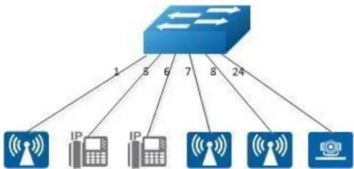
flowchart
graph TD
A["Router"] -->|1| B["IP 1"]
A -->|3| C["IP 2"]
A -->|6| D["IP 3"]
A -->|7| E["IP 4"]
A -->|8| F["IP 5"]
A -->|24| G["IP 6"]
A --> H["IP 7"]
Figure 19-1 PoE
Procedure
Define a time-range entry for working hours:
Switch# configure terminal
Switch(config)# time-range working
Switch(config-tm-range)# periodic 8:30 daily to 18:30
Switch(config-tm-range)# exit
Configuring a global power management scheme:
Switch(config)# poe power-management policy dynamic
Switch(config)# poe power-management limit-mode class
Configuring the PoE Power Supply Policy for the ports:
Switch(config)# interface eth-0-1
Switch(config-if)# poe disable
Switch(config-if)# poe enable time-range working
Switch(config-if)# exit
Switch(config)# interface range eth-0-5 - 6
Switch(config-if-range)# poe priority critical
Switch(config-if-range)# poe enable
Switch(config-if-range)# exit
Switch(config)# interface eth-0-24
Switch(config-if)# poe priority critical
Switch(config-if)# poe enable
Switch(config-if)# exit
Switch(config)# interface range eth-0-7 - 8
Switch(config-if-range)# poe priority high
Switch(config-if-range)# poe enable
Switch(config-if-range)# exit
Switch(config)#exit
Switch#
Save the configuration:
Switch# write
Switch#
- Table of Contents
- Preface....25
- Basic Configuration Guide....26
- Configuring Time&timezone....44
- Configuring License ....45
- RPC API Configuration Guide....47
- Configuring HTTP 52
- Ethernet Configuration Guide ....54
- Configuring Interface ....54
- Configuring Layer3 Interfaces....57
- Configuring Interface Errdisable 60
- Configuring MAC Address Table 64
- Configuring VLAN 69
- Configuring Voice VLAN....74
- Configuring VLAN Classification....76
- Configuring VLAN Mapping ....79
- Configuring Link Aggregation ....87
- Configuring Flow Control....94
- Configuring Storm Control....96
- Configuring Loopback Detection 99
- Configuring Layer 2 Protocols Tunneling 103
- Configuring MSTP 106
- Configuring MLAG 112
- Configuring Hash Load-balance 116
- IP Service Configuration Guide .... 137
- IP Routing Configuration Guide.... 161
- Configuring Prefix-list 220
- Configuring Route-map 224
- Configuring Policy-Based Routing.... 227
- Configuring BGP 232
- Configuring ISIS.... 238
- Multicast Configuration Guide 245
- Configuring IP Multicast-Routing 245
- Configuring IGMP 246
- Configuring PIM-SM 250
- Configuring PIM-DM 263
- Security Configuration Guide ...... 280
- Configuring COPP ACL 298
- Configuring dot1x.... 301
- Configuring Guest VLAN 308
- Configuring ARP Inspection.... 315
- Configuring DHCP Snooping 318
- Configuring IP source guard 321
- Configuring Private-vlan 325
- Configuring AAA 327
- Configuring TACACS+ 332
- Configuring Port Isolate 336
- Device Management Configuration Guide 344
- Network Management Configuration Guide 383
- Configuring Network Diagnosis 383
- Configuring NTP 385
- Configuring Phy Loopback 390
- Configuring L2 ping.... 393
- Configuring RMON 395
- Configuring SNMP 397
- Configuring SFLOW 403
- Configuring LLDP 406
- Configuring IPFIX....409
- Traffic Management Configuration Guide 412
- Configuring QoS....412
- IPv6 Service Configuration.... 433
- Configuring IPv6 over IPv4 Tunnel 433
- Configuring ND.... 451
- Configuring DHCPv6 Relay 453
- IPv6 Security Configuration Guide 457
- DHCPv6 Snooping Configuration 457
- IPv6 Routing Configuration 460
- Configuring IPv6 Unicast-Routing 460
- Configuring OSPFv3.... 463
- Configuring RIPng 492
- Configuring lpv6 Prefix-list.... 509
- IPv6 Multicast Configuration Guide....513
- Configuring CFM 564
- Configuring CPU Traffic 585
- Configuring G.8031 592
- Configuring G8032....596
- Configuring UDLD 619
- Configuring ERPS 621
- Configuring Smart Link.... 632
- Configuring Multi-Link 638
- Configuring Monitor Link.... 647
- DataCenter Configuration Guide....693
- List of Figures
- Preface
- Declaration
- Suggestion feedback
- Audience
- Basic Configuration Guide
- Configuring System Management
- Overview
- Function Introduction
- Principle Description
- Configuration
- Configuring a MOTD Login Banner
- step 1 Enter the configure mode
- step 2 Create the notification
- step 3 Exit the configure mode
- step 4 Validation
- Configuring a Login Banner
- Configuring an Exec Banner
- Application cases
- Case 1: mark the usage of the device
- Configuration steps
- Configuration files
- Configuring User Management
- Overview
- Configuration
- Configuring the user management in login local mode
- step 2 et username and password
- step 3 Enter the configure mode and set user management mode
- step 4 Exit the configure mode
- step 5 Validation
- Configuring the user management in login mode
- step 2 Enter the configure mode and set password
- Configuring Password recovery procedure
- Step 1 Power on the system. Boot loader will start to run. The follow information will be printed on Console.
- Step 2 Press ctrl+b. stop autoboot.
- Step 3 Under boot loader interface, use the following instructions.
- Application cases
- Configuring FTP
- Overview
- Configuration
- Downloading a configuration file by using FTP in IPv4 network
- step 1 copy the configuration file
- step 2 Validation
- Uploading a configuration file by using FTP in IPv4 network
- Downloading a configuration file by using FTP in IPv6 network
- Uploading a configuration file by using FTP in IPv6 network
- Application cases
- Configuring FTP SERVER
- Overview
- Configuration
- configuration of FTP server
- step 2 Enable FTP server on management interface
- step 3 Config switch system users
- Other optional configuration
- Config FTP server port, default is 21
- Config FTP server time-out, default is 15min
- Application cases
- Configuring TFTP
- Overview
- Configuration
- Downloading a configuration file by using TFTP in IPv4 network
- Uploading a configuration file by using TFTP in IPv4 network
- Downloading a configuration file by using TFTP in IPv6 network
- Uploading a configuration file by using TFTP in IPv6 network
- Application cases
- Configuring SCP
- Overview
- Configuration
- Downloading a configuration file by using SCP in IPv4 network
- Uploading a configuration file by using SCP in IPv4 network
- Downloading a configuration file by using SCP in IPv6 network
- Uploading a configuration file by using SCP in IPv6 network
- Application cases
- Configuring Telnet
- Overview
- Configuration
- Telnet switch with inner port
- Example 1 IPv4 Network
- Telnet switch with management port
- Configure telnet server
- Application cases
- Configuring SSH
- Overview
- Configuration
- Create key for SSH
- step 2 Create a key
- step 3 Create a private key named a.pri with key a and save it to flash
- step 4 Create a private key named a.pub with key a and save it to flash
- step 5 Exit the configure mode
- Import the key
- step 2 Import the key a.pub we created as importKey
- step 3 Create username and password
- step 4 Assign the key to user aaa
- Use SSH to connect
- step 1 Download the a.pri key on SSH client
- step 2 Connect to the client
- Application cases
- Configuring Time&timezone
- Overview
- Configuration
- step 2 Configuring time and timezone
- Application cases
- Configuring License
- Overview
- Configuration
- step 1 Create UDI for the device and send it to remote FTP server
- step 2 Apply license
- step 3 Use license
- NOTE
- RPC API Configuration Guide
- Overview
- Python Client Example Code
- Error code
- Configuration
- Configuring RPC API service
- step 2 Enable RPC API service
- Configuring RPC API service with HTTP Authentication
- Step 2 Set the username and password, then enable the rpc-api authentication
- Application cases
- Configuring HTTP
- Overview
- Configuration
- Preparatory
- Configure HTTP server
- step 2 Load WEB image
- step 3 Configure HTTP server address (Optional)
- step 4 Enable HTTP service
- step 6 Login the web via the browser
- Application cases
- Ethernet Configuration Guide
- Configuring Interface
- Overview
- Configuration
- Configuring Interface State
- step 2 Turn on an interface
- step 3 Shut down an interface
- Configuring Interface Speed
- step 2 Enter the interface configure mode and set the speed
- Configuring Interface Duplex
- step 2 Enter the interface configure mode and set the duplex
- Application cases
- Configuring Layer3 Interfaces
- Overview
- Configuration
- Configuring Routed Port
- step 2 Enter the interface configure mode and set IP address
- Configuring VLAN Interfaces
- step 2 Enter the vlan configure mode and create a vlan
- step 3 Enter the interface configure mode and set switch port attributes
- step 4 Enter the vlan interface configure mode and set IP address
- step 6 Validation
- Configuring Interface Errdisable
- Overview
- Configuration
- Configuring Errdisable Detection
- step 2 Enable detect link flap errdisable
- Configuring Errdisable Recovery
- step 2 Enable errdisable and set recovery interval
- Configuring suppress Errdisable link Flap
- step 2 Set link flap condition
- Checking Errdisable Status
- Case 1 Enable errdisable recovery
- Case 2 Disalbe errdisable recovery
- case 3 Display interface brief information to check errdisable state.
- Application cases
- Configuring MAC Address Table
- Overview
- Configuration
- Configuring Address Aging Time
- step 2 Set dynamic address aging time
- Configuring Static Unicast Address
- step 2 Set static mac address table
- Configuring Static Multicast Address
- step 2 Set static multicast mac address table
- Configuring MAC Filter Address
- step 2 Add unicast address to be discarded
- Application cases
- Configuring VLAN
- Overview
- Configuration
- Configuring Access Port
- step 2 Enter the vlan configure mode and create vlan
- step 3 Enter the interface configure mode, set the switch port mode and bind to the vlan
- Configuring Trunk Port
- Application cases
- Configuring Voice VLAN
- Overview
- Configuration
- step 3 Set the cos of voice vlan (Optional)
- step 4 Set the voice vlan and create a mac entry for it
- step 5 Enter the interface configure mode and enable voice vlan
- Application cases
- Configuring VLAN Classification
- Overview
- Configuration
- step 4 Apply the vlan classifier group on the interface
- Application cases
- Configuration
- Configuring VLAN Translation
- step 3 Create evc and set dot1q mapped vlan
- step 4 Create vlan mapping table and bind the vlan and evc
- step 5 Enable vlan translation on the interface and apply the vlan mapping table
- step 6 Exit the configure mode
- step 7 Validation
- Configuring 802.1q Tunneling (Basic 802.1Q tunneling)
- step 2 Enter the interface configure mode, set the switch port mode
- Configuring 802.1q Tunneling (Selective 802.1Q tunneling, Add one tag for incoming untagged packet.)
- Application cases
- Configuring Link Aggregation
- Overview
- Configuration
- Configure dynamic lacp
- step 2 Set the global attributes of LACP
- step 3 Enter the interface configure mode and add the interface to the channel group
- Configure channel-group
- Switch1 configuration:
- Switch2 configuration:
- Configuring Static-channel-group
- step 2 Enter the interface configure mode and add the interface to the channel group
- Application cases
- Configuring Flow Control
- Overview
- Configuration
- Configuring Flow Control Send
- step 2 Enter the interface configure mode and enable flowcontrol send
- Configuring Flow Control Receive
- Application cases
- Configuring Storm Control
- Overview
- Configuration
- Configuring Bandwidth Percentage Storm Control
- step 2 Enter the interface configure mode, and set the storm control level
- Configuring Packets per-Second Storm Control
- step 2 Enter the interface configure mode, and set the storm control pps
- Application cases
- Configuring Loopback Detection
- Overview
- Configuration
- Enable Loopback Detect
- step 2 Enter the interface configure mode, and enable Loopback Detect
- Configuring Loopback Detect packet interval
- step 2 set the packet interval of Loopback Detect
- Configuring Loopback Detect action
- step 2 Enter the interface configure mode, and set the action of Loopback Detect
- Configuring specify VLAN Loopback Detection
- step 2 Enter the interface configure mode, and set the specify vlan of Loopback Detect
- Application cases
- Configuring Layer 2 Protocols Tunneling
- Overview
- Configuration
- Tunnel Designed Layer2 Protocol Packets
- step 4 Enable l2 protocol, set the tunnel destination mac and add l2 protocao mac address
- step 5 Enter the interface configure mode and set the attributes of the interfaces. Bind the l2 protocol mac and the evc
- Application cases
- Configuring MSTP
- Overview
- Configuration
- step 2 Set the mode of STP
- step 3 Enter the vlan configure mode and create vlan
- step 4 Enter the MSTP configure mode, create region and instance. Bind the vlan to the instance.
- step 6 Enable STP and set priority for each swicth
- step 7 Exit the configure mode
- step 8 Validation
- Switch# show spanning-tree mst brief
- Application cases
- Configuring MLAG
- Overview
- Configuration
- step 3 Create a static agg
- step 4 Set the attributes of the peer link interface
- step 5 Bind the agg interface to the mlag
- step 6 Set the attributes of the vlan interface
- step 7 Enter the mlag configure mode and set the attributes of the mlag
- Application cases
- Configuring Hash Load-balance
- Configuring Linkagg Hash
- Overview
- Configuring Linkagg Hash Globally
- step 2 Set hash field
- step 3 Set hash value global
- Configuring Linkagg Hash Input
- step 3 Set hash value
- Configuring Linkagg Hash output
- Configuring Linkagg Hash ACL
- step 4 Add acl action to interface and set hash value to interface
- Configuring Non-unicast Linkagg Hash
- step 4 Set hash value to interface
- Configuring ECMP Hash
- Configuring ECMP Hash Globally
- Configuring ECMP Hash Input
- Configuring ECMP Hash
- Configuring EFD Hash Globally
- step 2 Set hash global
- step 3 Validation
- Configuring PORT-XCONNECT
- Overview
- Configuration
- Application cases
- IP Service Configuration Guide
- Configuring Arp
- Overview
- Configuration
- step 2 Configure the layer 3 interface and set the ip address
- step 3 Configure arp aging timeout value and the arp retry interval value
- step 4 Add a static arp entry
- Application cases
- Configuring Arp proxy
- Overview
- Configuration
- Configuring ARP Proxy
- step 4 Create the vlan interface, configure the ip address, and enable arp proxy
- Configuring Local ARP Proxy
- step 4 Create the vlan interface, configure the ip address, and enable local arp proxy
- step 5 Configuring port isolation(optional)
- Application cases
- Configuring DHCP Client
- Overview
- Configuration
- step 2 Enter the interface configure mode
- step 3 disable static-route and enable DHCP client
- Application cases
- Configuring DHCP Relay
- Overview
- Configuration
- step 2 Enter the interface configure mode, set the attributes and ip address
- step 3 Create a dhcp server
- step 4 Enable DHCP server and option82 for the interface
- step 5 Enable DHCP server and DHCP relay globally
- Check the interface configuration
- Application cases
- Configuring DHCP server
- Overview
- Configuration
- Configuring DHCP server
- step 2 Enable DHCP server globally, configure the ip address pool
- step 3 Enter the interface configure mode, set the attributes and ip address
- Configuring DHCP server with relay
- step 2 Enable DHCP server globally, configure the ip address pool and DHCP relay
- step 2 Add a ip route
- step 4 Enter the interface configure mode, set the attributes and ip address
- Configure on DUT1:
- Configure on DUT2:
- Configure on DUT3:
- Check DHCP Server(dut1) configuration:
- Application cases
- Configuring DNS
- Overview
- Configuration
- step 2 Set the dns domain name and dns server address
- step 3 Set static hostname-to-address mappings (optional)
- Configuring IP Unicast-Routing
- Overview
- Configuration
- Configure on Switch1:
- Configure on Switch2:
- step 3 Configuring static route
- Application cases
- Configuring RIP
- Overview
- Configuration
- Enabling RIP
- step 3 Enable RIP routing process and associate networks
- Configuring The RIP Version
- step 2 Enable RIP routing process
- step 3 Enter the interface configure mode and set the version for sending and receiving rip packets
- Configuring Metric Parameters
- step 1 precondition
- step 2 Enter the configure mode
- step 3 Configuring access list
- step 4 Enable RIP routing process and set offset list and offset value for an interface
- Configuring the Administrative Distance
- step 4 Enable RIP routing process and set administrative distance
- Configuring Redistribution
- Configuring Split-horizon Parameters
- step 2 Enabling debug on Switch2 (optional)
- step 3 Enter the configure mode
- step 4 Enter the interface configure mode and set split-horizon
- Configuring Timers
- step 2 Enable RIP routing process and set the timers
- Configuring RIP Route Distribute Filters
- Switch1
- Switch2
- step 3 Configuring prefix list
- step 4 Apply prefix list
- Configuring RIPv2 authentication (single key)
- Configuring RIPv2 MD5 authentication (multiple keys)
- Application cases
- Configuring OSPF
- Overview
- Configuration
- Basic OSPF Parameters Configuration
- step 2 Configure the Routing process and associate the network with a specified OSPF area
- Enabling OSPF on an Interface
- step 3 Configure the Routing process and associate the network with a specified OSPF area
- Switch1:
- Switch2:
- Configuring Priority
- step 3 Specify the router priority
- step 4 Configure the Routing process and associate the network with a specified OSPF area
- Switch3:
- Configuring OSPF Area Parameters
- Configure on Switch3:
- Configure on Switch4:
- Configure on L2 Switch:
- step 3 Set the ospf priority on the interface
- Redistributing Routes into OSPF
- step 5 Enable RIP routing process and associate networks
- OSPF Cost
- step 2 Enter the interface configure mode, set the attributes and ip address.
- Set the ospf cost under the interface configure mode
- Configuring OSPF authentications
- step 2 Enter the interface configure mode, set the attributes and ip address. Set the ospf authentication under the interface configure mode
- Application cases
- Configuring OSPF authentications password encryption
- Simple Password
- MD5 Password
- step 2 Enter the interface configure mode, set the attributes and ip address. Set the ospf authentication under the interface configure mode and simple password
- step 3 Enter the configure mode, translate to encryption password and show it
- step 4 Disable the function of showing encryption password, delete the old authentication-key and set new one, then show the password
- step 5 Configuring OSPF encryption password
- Application cases
- Configuring Prefix-list
- Overview
- Configuration
- Basic Configuration
- step 2 Create a prefix-list
- Used by rip
- step 3 Apply the prefix-list under the router rip configure mode
- Used by Route-map
- Application cases
- Configuring Route-map
- Overview
- Configuration
- Configuring Route-map for OSPF
- step 2 Create route map and set the rule and action
- step 3 Enter the router ospf configure mode, redistribute rip routes and apply the route map
- Configuring Route-map for BGP
- Application cases
- Configuring Policy-Based Routing
- Overview
- Configuration
- PBR Configuration
- step 2 Create an ip access list to match source ip address
- step 3 Create a route map, to match the ip access list and set the nexthop ip
- step 4 Enter the interface configure mode, set the attributes and ip address, and apply the route map
- step 5 Create a static route with the nexthop ip 172.16.4.3 (optional)
- Configure PBR and BFD linkage
- Application cases
- Configuring BGP
- Overview
- Configuration
- Configure EBGP
- step 2 Enter the interface configure mode and set the attributes
- step 3 Configure a static route
- step 4 Configure the Routing process and set the router id, set the neighbor, associate the network, and set the redistribute attributes
- Configure IBGP
- Application cases
- Configuring ISIS
- Overview
- NET
- ISIS area
- Configuration
- step 2 Configure the Routing process and set the net
- step 3 Enable ipv4 isis on the interface
- Display the result on Switch2:
- Application cases
- Multicast Configuration Guide
- Configuring IP Multicast-Routing
- Overview
- Configuration
- Configuring multicast route limit
- step 2 set the limit of the multicast route
- Application cases
- Configuring IGMP
- Overview
- Configuration
- step 2 Enable ip multicast-routing globally
- step 4 Enable pim-sm on the interface
- step 5 Set the attributes for igmp
- step 6 Set the maximum igmp group count(optional)
- step 7 Set a static igmp group
- step 8 Set igmp proxy(optional)
- step 9 Exit the configure mode
- step 10 Validation
- Application cases
- Configuring PIM-SM
- Overview
- Configuration
- Configuring General PIM Sparse-mode (static RP)
- step 2 Enter the interface configure mode, set the attributes and ip address, and enable pim-sm
- step 3 Add static routes
- step 4 Configure the static rp address
- Configuring General PIM Sparse-mode (dynamic RP)
- step 4 Configure the rp candidate
- Configuring Bootstrap Router
- step 2 Configure the bsr candidate and rp candidate
- step 3 Configure the priority of rp candidate
- step 4 Configure the priority of dr and enable receive and send unicast bsm packets
- Verify RP-set information on E-BSR
- Verify RP-set information on C-BSR
- Configuring PIM-SSM feature
- step 2 Enable ssm
- Application cases
- Configuring PIM-DM
- Overview
- Configuration
- step 2 Enter the interface configure mode, set the attributes and ip address, and enable pim-dm
- Application cases
- Configuring IGMP Snooping
- Overview
- Configuration
- Enable Globally Or Per Vlan
- step 2 Enable igmp snooping globally and per-vlan
- Configuring Fast Leave
- step 2 Enable Fast Leave globally and per-vlan
- Configuring Querior Parameters
- step 2 Set the global attributes of igmp snooping
- step 3 Set the per-vlan attributes of igmp snooping
- Configuring Mrouter Port
- step 2 Enable igmp snooping report suppression globally
- step 3 Configure mrouter port, Enable igmp snooping report suppression, and set igmp snooping dynamic mrouter port aging interval for a vlan
- Configuring Querier TCN
- step 2 Configuring the TCN querier count and querier interval
- Configuring Report Suppression
- step 2 Enable Report Suppression globally and per-vlan
- Configuring Static group
- step 2 Configure static group
- Application cases
- Configuring MVR
- Overview
- Configuration
- step 3 Enter the interface configure mode, set the attributes and ip address, and enable pim-sm
- step 4 Enable MVR
- Application cases
- Security Configuration Guide
- Configuring Port Security
- Overview
- Configuration
- step 2 Enter the interface configure mode, set the attributes, and enable pim-sm
- Application cases
- Configuring Vlan Security
- Overview
- Configuration
- Configuring vlan mac-limit
- step 2 Enter the vlan configure mode and create vlan, set the the maximum of MAC addresses and the action at exceeding
- Configuring vlan mac learning
- step 2 Enter the vlan configure mode and create vlan, set the mac learning states
- Application cases
- Configuring Time-Range
- Overview
- Configuration
- Create an absolute time range
- Create a periodic time range
- Application cases
- Configuring ACL
- Overview
- Configuration
- step 2 Create access list
- step 3 Create class-map, and bind the access list
- Application cases
- Configuring Extern ACL
- Overview
- Configuration
- step 4 Create policy-map and bind the class map
- Application cases
- Configuring IPv6 ACL
- Overview
- Configuration
- step 2 Enable IPv6 globally
- step 3 Create access list
- step 4 Create class-map, and bind the access list
- Application cases
- Configuring Port-Group
- Overview
- Configuration
- Create a port group
- step 2 Create a port group and add member interfaces
- Application cases
- Configuring Vlan-Group
- Overview
- Configuration
- Create a vlan group
- Application cases
- Configuring COPP ACL
- Overview
- Configuration
- step 2 Create copp access list
- step 3 Create class-map, and bind the copp access list
- step 5 Apply the policy to the interface
- Application cases
- Configuring dot1x
- Overview
- Configuration
- Basic dot1x configuration
- step 2 Enable dot1x globally
- step 3 Enter the interface configure mode, set the attributes of the interface and enable dot1x
- step 4 Set the attributes of Layer 3 interface and set the Radius server
- Enable dot1x on routed port
- Using force mode
- Enable dot1x accounting
- dot1x optional parameter
- Application cases
- Radius server configuration (Using WinRadius for example)
- Configuring Guest VLAN
- Overview
- Configuration
- step 3 Enable dot1x globally
- step 4 Enter the interface configure mode, set the attributes of the interface and enable dot1x and set guest vlan
- step 5 Set the attributes of Layer 3 interface and set the Radius server
- authorized:
- Application cases
- Configuring ARP Inspection
- Overview
- Configuration
- Application cases
- Configuring DHCP Snooping
- Overview
- Configuration
- Application cases
- Configuring IP source guard
- Overview
- Configuration
- Configure ip source guard
- step 3 Enter the interface configure mode and set the attributes
- step 4 Add IP source guard entries
- step 5 Enable IP source guard on the interface
- step 6 Allow forwarding of ARP packets
- Remove ip source guard entries
- Application cases
- Configuring Private-vlan
- Overview
- Configuration
- Application cases
- Configuring AAA
- Overview
- Configuration
- step 2 Enable AAA
- step 3 Configure Radius server
- step 4 Configure a layer 3 interface and set ip address
- step 5 set authentication mode
- Application cases
- Configuring TACACS+
- Overview
- Configuration
- step 3 Configure tacacs+ server
- Application cases
- Radius server configuration
- Configuring Port Isolate
- Overview
- Configuration
- step 2 Set the port isolate mode globally
- step 3 Enter the interface configure mode and set isolate group
- Application cases
- Configuring DDoS
- Overview
- Configuration
- step 2 Set DDoS
- Enable packet source IP equals destination IP intercept
- Enable packet source MAC equals destination MAC intercept
- Application cases
- Configuring Key Chain
- Overview
- Configuration
- step 2 Create key chain and set key
- Application cases
- Configuring Port-Block
- Overview
- Configuration
- step 2 Enter the interface configure mode and block unknown unicast
- Application cases
- Device Management Configuration Guide
- Configuring STM
- Overview
- Configuration
- step 2 Set STM profile(use layer3 for example)
- step 5 Reboot the device
- Application cases
- Configuring syslog
- Overview
- Configuration
- Configuring Logging server
- step 2 Enable logging server and set the attributes
- Configuring Logging Buffer Size
- step 2 Set the logging Buffer Size
- Application cases
- Configuring mirror
- Overview
- Mirror session
- Mirror direction
- Mirror source
- Mirror destination
- Configuration
- Configuring Local port mirror
- step 2 Set the destination of mirror
- step 3 Set the source of mirror
- Configuring local vlan mirror
- step 3 Enter the vlan configure mode and create a vlan
- step 4 Create a vlan interface
- step 5 Set the source of mirror
- Configuring CPU as mirror source
- Configuring Multi-destination Mirror
- step 2 Set the destination group of mirror
- Configuring Remote Mirror
- The configuration of Switch2:
- method 1: use vlan 15 as mirror source, eth-0-2 as mirror destination
- method 2: add both ports in to the same vlan (15), and make the packet flood in this vlan
- method 3: flood in vlan and keep vlan tag 15
- Configuring CPU Mirror Dest
- Optional steps
- This example shows how to display the mirror cpu packets
- This example shows how to display the mirror buffer size:
- This example shows how to display the mirror cpu traffic-limit rate:
- Application cases
- Configuring Device Management
- Overview
- Configuration
- Configuring console port for management
- step 2 Enter line configuration mode and set the console speed
- Configuring out band Ethernet port for management
- step 2 Configure switch management address
- Configuring Temperature
- step 2 Configuring temperature threshold
- Configuring Fan
- Configuring Power
- Configuring Transceiver
- Upgrade bootrom
- step 1 Copy bootrom image file to the flash
- step 3 Upgrade the bootrom
- step 5 Reboot the system
- Upgrade EPLD
- step 1 Copy epld image file to the flash
- step 3 Upgrade the epld
- Application cases
- Configuring Bootrom
- Overview
- Configuration
- Configuring Boot from TFTP Server
- Method 4: Boot the system from TFTP server and reboot automatically without password
- Validation
- Configuring Boot from FLASH
- Boot the system from FLASH
- Boot the system from without password
- Boot the system from FLASH and reboot automatically
- Boot the system from FLASH and reboot automatically without password
- Set boot IP
- Set gateway IP
- Application cases
- Configuring SmartConfig
- Overview
- Configuration
- Enable smartConfig
- step 2 Enable smartConfigure
- Using smartConfig
- step 1:
- step 2:
- step 3:
- step 4:
- Application cases
- Reboot Logs
- Overview
- Configuration
- step 2 Clear the logs(optional)
- Application cases
- 9
- Network Management Configuration Guide
- Configuring Network Diagnosis
- Overview
- Configuration
- Ping IP with in-band port
- Ping IP with management port
- Ping IP with VRF instance
- Traceroute IP with inner port
- Application cases
- Example for Ping
- Example for traceroute
- Configuring NTP
- Overview
- Configuration
- Configuring Client/Server mode connecting with in-band interface
- step 3 Enter the interface configure mode and join the vlan
- step 4 create a vlan interface and set the IP address
- step 5 Set the attributes of NTP client
- Configuring Client/Server mode connecting with management interface
- step 2 Enable ntp management interface
- step 3 Set the attributes of NTP client
- Application cases
- Step 1 Display eth1 ip address
- Step 5 Start ntpd service
- Configuring Phy Loopback
- Overview
- Configuration
- Configuring external phy loopback
- step 2 Enter the interface configure mode and set loopback phy external
- Configuring internal phy loopback
- step 2 Enter the interface configure mode and set loopback phy internal and specify the destination interface
- Configuring port level loopback
- step 2 Enter the interface configure mode and set loopback phy mac-address swap
- Application cases
- Configuring L2 ping
- Overview
- Configuration
- step 2 Enter the interface configure mode and turn up the interface
- step 3 Enable the L2 ping response function
- step 5 Using L2 ping
- Application cases
- Configuring RMON
- Overview
- Configuration
- Application cases
- Configuring SNMP
- Overview
- Configuration
- Enable SNMP
- step 2 Enable SNMP globally
- Configuring community string
- step 2 Configuring community string
- Configuring SNMPv3 Groups, Users and Accesses
- step 2 Set the globle configurations for SNMP
- SNMPv1 and SNMPv2 notifications configure
- step 2 Set the global configurations for SNMP
- Configuring SNMPv3 notifications
- Application cases
- Configuring SFLOW
- Overview
- Configuration
- step 2 Enable sflow globally
- step 3 Set the global attribute for sflow
- step 4 Enter the interface configure mode and set the attributes of the interfaces
- step 5 Enable sflow for input packets on eth-0-1
- Application cases
- Configuring LLDP
- Overview
- Configuration
- step 3 Enter the interface configure mode and set the attributes of LLDP on the interface
- step 4 Set LLDP timers (optional)
- Configuring IPFIX
- Overview
- Configuration
- step 2 Set the aging time(optional)
- step 3 Configuring recorder
- Application cases
- 10
- Traffic Managemant Configuration Guide
- Configuring QoS
- Overview
- ACL
- CoS Value
- DSCP Value
- IP-Precedence Value
- EXP Value
- Classification
- Shaping
- Policing
- Marking
- Queuing
- Tail Drop
- WRED
- Scheduling
- Class Map
- Policy Map
- Mapping Tables
- Time-range
- SRTCM
- TRTCM
- CIR
- CBS
- EIR
- EBS
- PIR
- PBS
- Modular QoS CLI
- class-map type qos
- policy-map type qos
- class-map type traffic-class
- policy-map type traffic-class
- Configuration
- Classify Traffic Using ACLs
- step 2 Create ACL and ACEs
- Create class-map
- step 3 Create class-map and match the ACL
- Create Policy Map
- step 5 Enter the interface configure mode and apply the policy-map
- Create Aggregate Policer
- step 3 Create an aggregate-policer
- step 4 Create class-map and match the ACL
- step 5 Create policy-map and match the class-map; Apply the aggregate-policer in policy-class configure mode
- step 6 Enter the interface configure mode and apply the policy-map
- Configuration for Queue
- Configuring Schedule
- step 1 Enter the configure mod
- step 2 Create class-map and match the traffic-class
- step 3 Create policy-map and match the class-map ; Set the priority in policy-class configure mode
- step 4 Enter the interface configure mode and apply the policy-map
- Configuring Tail Drop
- Configuring WRED
- step 3 Create policy-map and match the class-map
- step 4 Set the threshold for WRED in policy-class configure mode
- Queue shaping
- step 4 Set the shape rate in policy-class configure mode
- Configuration for Port shaping & port policing
- Configuring Port policing
- step 2 Enter the interface configure mode and set the policer rate
- Configuring Port shaping
- step 2 Enter the interface configure mode and set the shape rate
- Application cases
- IPv6 Service Configuration
- Configuring IPv6 over IPv4 Tunnel
- Overview
- Manual Tunnel
- 6to4 Tunnel
- Ordinary 6to4 tunnel
- 6to4 relay
- ISATAP Tunnel
- Configuration
- step 3 Enter the interface configure mode and set the attributes of the interface
- step 4 Create static routes
- Configuring Switch1:
- Configuring Switch2:
- step 5 Configuring static arp
- Display the result on Switch1:
- Configure 6to4 Tunnel
- Configure 6to4 relay
- Configure ISATAP Tunnel
- Configure ISATAP host
- Application cases
- Configuring ND
- Overview
- Configuration
- step 2 Enter the interface configure mode and set the attributes of the interface
- step 3 Add a static neighbor entry
- Application cases
- Configuring DHCPv6 Relay
- Overview
- Configuration
- step 2 Enable DHCPv6 relay globally
- step 3 Configure the DHCPv6 server
- step 4 Enter the interface configure mode and set the attributes of the interface
- Application cases
- IPv6 Security Configuration Guide
- DHCPv6 Snooping Configuration
- Overview
- Configuration
- step 2 Enter the vlan configure mode and create the vlan
- step 4 Enable DHCPv6 snooping globally and set the attributes
- Check the dhcpv6 service status.
- Show dhcpv6 snooping statistics.
- Enable DHCPv6 snooping global feature
- Step 5 Show dhcpv6 snooping binding information
- Application cases
- IPv6 Routing Configuration
- Configuring IPv6 Unicast-Routing
- Overview
- Configuration
- Application cases
- Configuring OSPFv3
- Overview
- Configuration
- Basic OSPFv3 Parameters Configuration
- step 2 Create OSPFv3 instance
- Enabling OSPFv3 on an Interface
- step 3 Create OSPFv3 instance
- Configuring OSPFv3 Area Parameters
- Configuring Switch3:
- Configuring Switch4:
- Interface configuration for Switch1:
- Redistributing Routes into OSPFv3
- step 4 Create RIPng instance
- step 5 Enter the interface configure mode and set the attributes of the interface
- Configure OSPFv3 Cost
- Monitoring OSPFv3
- Display OSPFv3 interface neighbor information
- Application cases
- Configuring RIPng
- Overview
- Configuration
- Enabling RIPng
- Interface configuration for Switch2:
- step 1 Check the current configuration
- step 4 Apply the access list
- step 3 Change the administrative distance
- Enable debug on switch2
- step 3 Set the split-horizon on interface configure mode
- Disable split-horizon:
- System debug information:
- Enable split-horizon:
- step 2 Set the timers
- Configuring RIPng Route Distribute Filters
- step 3 Create IPv6 Prefix list
- step 4 Apply the IPv6 Prefix list
- Application cases
- Configuring IPv6 Prefix-list
- Overview
- Configuration
- step 2 Create IPv6 Prefix list
- Used by RIPng
- Step 3 Apply the IPv6 Prefix list
- step 3 Apply the IPv6 Prefix list to the route map
- Application cases
- 14
- IPv6 Multicast Configuration Guide
- Configuring IPv6 Multicast-Routing
- Overview
- Configuration
- Configuring IPv6 multicast route limit
- step 2 Set the limit of the IPv6 multicast route
- Application cases
- Configuring MLD
- Overview
- Configuration
- step 2 Enable ipv6 and ipv6 multicast-routing globally
- step 3 Enter the interface configure mode, set the ipv6 address and enable pim sparse mode
- step 4 Configuring MLD Interface Parameters
- step 5 Limit Max MLD Group Number
- Application cases
- Configuring PIMv6-SM
- Overview
- Configuration
- Configuring General PIMv6 Sparse-mode (With static RP)
- step 2 Enable IPv6 & IPv6 multicast globally
- step 4 Create static unicast routes
- step 5 Configure static RP address
- RP Details
- Interface Details
- IPv6 Multicast Routing Table
- Configuring General PIMv6 Sparse-mode (With dynamic RP)
- step 5 Configure the candidate rp
- step 6 Configure the candidate bsr
- PIMv6 group-to-RP mappings
- step 3 Configure the candidate bsr
- step 4 Configure the candidate rp
- Configuring PIMv6-SSM feature
- step 2 Enable PIMv6-ssm globally
- Application cases
- Configuring PIMv6-DM
- Overview
- Configuration
- Configuring General PIM dense-mode
- Neighbor Details
- IP Multicast Routing Table
- Application cases
- Configuring MLD Snooping
- Overview
- Configuration
- Enable MLD Snooping
- step 2 Enable mld snooping globally
- step 3 vlan 使能 mld snooping
- step 2 Enable fast leave globally
- step 3 Enable fast leave for a vlan
- Configuring Querier Parameters (optional)
- step 2 Configuring Querier Parameters for MLD snooping
- step 2 Enable mld snooping report suppression globally
- step 3 Configure mrouter port
- step 4 Configure mld snooping for parameters vlan
- step 2 Set the parameters for MLD Snooping querier TCN
- step 3 Enable mld snooping report suppression for a vlan
- Application cases
- Configuring MVR6
- Overview
- Configuration
- step 2 Enter the vlan configure mode and create VLANs
- step 4 Enable MVR6
- Application cases
- VPN Configuration Guide
- Configuring VPN
- Overview
- Configuration
- step 2 Create a vrf instance
- Application cases
- Configuring IPv4 GRE Tunnel
- Overview
- Configuration
- step 3 Configure the tunnel interface
- step 4 Configure the static route and arp
- Application cases
- Reliability Configuration Guide
- Configuring BHM
- Overview
- Configuration
- step 2 Enable system monitor and heart-beat-monitor globally
- step 3 Reload system if a monitored PM is uncontrolled
- Application cases
- Configuring EFM OAM
- Overview
- Configuration
- Configuring Enable EFM
- step 2 Enter the interface configure mode and enable ethernet oam
- Configuring Remote Loopback
- step 2 Enter the interface configure mode and enable ethernet oam remote loopback
- step 4 Start remote loopback
- Configuring Link Monitoring Event
- step 2 Enter the interface configure mode and set the threshold for error packetes
- step 3 Set the action when reach the threshold
- Configuring Remote Failure Detection
- step 2 Enter the interface configure mode and set action when the remote link failure
- Application cases
- Configuring CFM
- Overview
- Continuity Check messages (CC)
- Loopback messages
- Linktrace messages
- Delay Measurement messages
- Ethernet Locked Signal messages
- Ethernet client signal fail messages
- Ethernet Frame loss measurement message
- Configuration
- Configure CC/LB/LT/AIS/DM
- step 3 Enable CFM globally and set cfm mode to y1731
- step 4 Create the cfm domain and bind the service with a vlan
- Interface configuration for Switch4:
- step 6 Enable continuity check
- step 7 Alarm configuration (optional)
- step 8 Exit the configure mode
- step 9 Validation
- MEP and MIP checks
- Loopback checks
- RDI checks
- ERROR checks
- AIS check
- LinkTrace checks
- 1DM and DMM checks
- Configure LCK
- step 1 Configuration prepare
- step 2 Configure LCK
- Configure CSF
- step 7 Configure csf relation between client mep and server mep
- Configure Dual-Ended LM
- step 2 Configure Dual-Ended LM
- The following command is used to display lm status for Switch4.
- step 2 Configure Single-Ended LM
- Configure Test
- step 2 Configure Test
- Configuring CPU Traffic
- Overview
- Configuration
- step 2 Set the total rate
- step 3 Set the saparate rate
- step 4 Set the reason class
- Application cases
- Configuring G.8031
- Overview
- Configuration
- step 6 Create G8031 group and bind the mstp instance
- Application cases
- Configuring G8032
- Overview
- Topology
- Configuration of single ring
- step 7 Configuration of Switch4
- step Switch4 validation
- Configuration of multiple rings - Non-virtual-channel
- step 3 Configuration of Switch2
- step 4 Switch2 validation
- step 5 Configuration of Switch3
- Configuration of multiple rings - Virtual-channel
- Linkage between G8032 and CFM
- Configuring UDLD
- Overview
- Configuration
- step 2 Enter the interface configure mode and enable udd
- step 3 Enable udld globally
- step 4 Set the message interval (optional)
- Application cases
- Configuring ERPS
- Overview
- Configuration
- Configuring ERPS for a Single-Ring Topology
- step 4 Create and enable ERPS domain.
- Display the result on Switch2.
- Configuring a Intersecting-Ring Topology
- Interface eth-0-20 configuration for Switch2 and Switch3:
- Display the result on Switch3.
- Application cases
- Configuring Smart Link
- Overview
- Configuration
- step 5 Create smart link group and set the attributes of the group
- step 6 Disable the smart link relay function
- Application cases
- Configuring Multi-Link
- Overview
- Configuration
- step 3 Set the spanning tree mode and create mstp instance
- Interface configuration for Switch1 \~ 5:
- step 5 Create multi link group and set the attributes of the group
- Application cases
- Configuring Multi-Link Enhance
- Configuring Monitor Link
- Overview
- Configuration
- step 2 Enter the interface configure mode and turn on the interface
- step 3 Create multi link group and set the attributes of the group
- Application cases
- Configuring VRRP
- Overview
- Terminology
- Configuration
- step 3 Create an instance of vrrp
- step 4 Set the priority (optional)
- step 5 Enable vrrp and Exit the vrrp configure mode
- Configuring VRRP (Two Virtual Router)
- VRRP Circuit Failover
- step 3 Create an track object to monitor the link state
- step 4 Create an instance of vrrp
- Application cases
- Configuring Track
- Overview
- Configuration
- Configuring IP SLA for interfaces in the VRF
- step 4 Create ip sla and set the attributes
- Parameters for ip sla:
- step 5 Enable ip sla
- Configuring IP SLA for Layer3 interfaces
- Figure 16-27 IP SLA
- step 3 Create ip sla and set the attributes
- step 4 Enable ip sla
- Configuring IP SLA for outgongin interface of static route
- Figure 16-28 IP SLA
- Configuring track interface linkstate
- step 2 Create track and set the attributes
- []Parameters for track:
- Configuring track ip sla reachability
- step 3 Create ip sla and enable it
- step 4 Create track and set the attributes
- Configuring track ip sla state
- Configuring track bfd
- Configuring track for vrrp
- step 1 Check current configuration
- step 3 Apply track for vrrp
- Configuring track for static route
- step 5 Apply track for static route
- Application cases
- Configuring IP BFD
- Overview
- Configuration
- Configuring BFD single-hop
- step 3 Configuring ospf
- step 4 Configuring VRRP
- step 5 Configuring static route
- Configuring BFD multi-hop
- Application cases
- Configuring VARP
- Overview
- Configuration
- step 2 Set the virtual-router mac address
- step 3 Enter the vlan configure mode and create the vlan
- step 5 Create the vlan interface and set ip and virtual router ip
- Application cases
- Configuring UDP Helper
- Overview
- Configuration
- step 2 Enable UDP Helper
- step 3 Configure the IP address and UDP Helper Server IP address on interface
- step 4 configure the ARP
- Application cases
- DataCenter Configuration Guide
- Configuring VXLAN
- Overview
- Configuration
- Vxlan Configuration
- step 2 Enter the vlan configure mode and create vlan, enable overlay for each vlan
- Step 4 Create a static route
- Step 5 Set attributes for overlay
- Configuring VXLAN Routing
- step 3 Create a vrf instance
- step 4 Create the layer 3 interface and set the ip address
- Step 6 Set attributes for overlay
- step 7 Create a static routes and vxlan routes
- Configuring VXLAN Distributed Routing by EBGP EVPN
- step 3 Create vlan mapping vni for vxlan
- step 4 Create evpn instance
- step 5 Create a vrf instance, and enable EVPN
- step 6 Create the layer 3 interface, set the ip address and enable distributed gateway
- step 7 Enter the interface configure mode and set the attributes of the interface
- Step 8 Create NVE
- Step 9 Create BGP EVPN
- step 10 Create a static routes
- Configuring VXLAN Distributed Routing by IBGP EVPN
- step 10 Exit the configure mode
- step 11 Validation
- Configuring NVGRE
- Overview
- Configuration
- NVGRE Configuration
- Configuring NVGRE Routing
- step 7 Create a static routes and NVGRE routes
- Application cases
- Configuring GENEVE
- Overview
- Configuration
- GENEVE Configuration
- Configuring GENEVE Routing
- step 7 Create a static routes and GENEVE routes
- Application cases
- Configuring Overlay
- Overview
- Configuration
- Figure 17-9 Overlay multiple source ip
- Configuring OVERLAY without Horizon Split
- Application cases
- Configuring Prioprity-based Flow Control
- Overview
- Configuration
- step 2 Enable lldp globally
- Application cases
- Configuring OVSDB
- Overview
- Configuration
- step 3 Create static routes
- step 4 Set attributes for overlay
- step 5 Enable ovsdb globally
- Application cases
- Configuring EFD
- Overview
- Configuration
- step 1 Set the parameters for EFC
- step 4 Create a static arp entry (Optional)
- Application cases
- MPLS Configuration Guide
- Configuring LDP
- Overview
- Configuration
- LDP Configuration
- step 3 Enable router ldp
- step 4 Enable router rip
- Configuring MPLS
- Overview
- Configuration
- MPLS LSP Configuration
- step 3 Configure static ftn/ilm
- Application cases
- Configuring VPLS
- Overview
- Configuration
- Configuring VPLS using LDP
- step 6 bind the interface and the VPLS instance
- Configuring VPLS using static command
- step 3 Configure ftn entry
- step 4 Create a VPLS instance
- step 5 bind the interface and the VPLS instance
- step 6 Configure VPLS FIB
- step 7 Configure static ilm
- Configuring Tunnel L2 protocol packets by VPLS
- step 2 Enable L2 protocol globally
- step 4 Enable router ldp
- step 5 Enable router rip
- step 6 Create a VPLS instance
- step 7 bind the interface and the VPLS instance
- Configuring static MAC entries for VPLS
- step 5 Create a VPLS instance
- Application cases
- Configuring VPWS
- Overview
- Configuration
- Configuring VPWS using LDP
- step 4 Configure VPWS VC ID
- VC configuration using static command
- step 4 Configure static ilm
- step 5 Configure VPWS VC ID
- Configuring Tunnel L2 protocol packets by VPWS
- Interface configuration for PE1:
- Interface configuration for PE2:
- LDP configuration for PE1:
- Application cases
- Configuring MPLS QoS
- Overview
- MPLS LSP Model
- Configuration
- MPLS QoS Uniform Configuration
- step 2 Set MPLS LSP Model
- Interface configuration for P:
- step 4 Configure static arp
- step 5 Configure static ftn/ilm
- MPLS QoS Pipe Configuration
- MPLS QoS Short Pipe Configuration
- Static ilm for PE2:
- Display the result on PE1:
- Display the result on P:
- Display the result on PE2:
- Application cases
- Configuring L3VPN
- Overview
- Configuration
- Configuring L3VPN
- step 2 Set vrf
- step 6 Enable router ospf
- step 7 Enable router bgp
- Application cases
- PoE
- PoE Overview
- features and configurations
- Configuring Global PoE power management scheme
- Configuring power-reserved
- Configure threshold-power-percentage
- Enable port PoE feature
- Configuring the Power Supply Priority
- Trigger an autoclass measurement
- Example for Configuring PoE
- Networking Requirements
- Define a time-range entry for working hours:
- Configuring a global power management scheme:
- Configuring the PoE Power Supply Policy for the ports:
- Save the configuration:
Brand : AIRLIVE
Model : L3D-2TX4806-40GF
Category : Switch