
EBP VC1 EU - Matériel électronique de contrôle Extron - Free user manual and instructions
Find the device manual for free EBP VC1 EU Extron in PDF.


| Product Type | eBUS Button Panel |
| Brand | Extron |
| Model | EBP VC1 EU |
| Mounting | EU 55mm wall frame (one-gang EU junction box) |
| Button Type | Backlit, soft-touch buttons |
| Power Supply | 12 VDC via eBUS (max 1.5 W per device) |
| Connector Type | 4-pole 3.5 mm captive screw (input and output) |
| Status Indication | Single monochrome or bicolor LED |
| eBUS Addressing | 6-pole DIP switch, 63 unique addresses |
| Maximum Devices per Controller | 8 |
| Maximum Total Cable Run | 1000 ft (305 m) |
| Supported Topologies | Daisy-chain, star, hybrid |
| Recommended Cable | Extron STP20-2 serial control cable (22 AWG) |
| Alternative Cable | CAT5e/6 (with correct wiring) |
| Power Injection Support | Yes (via PS 1210P or PS 1220EB) |
| Voltage Monitoring | Via Extron Toolbelt software |
| Software Support | Global Configurator Plus/Professional, Global Scripter, Toolbelt |
| Firmware Update | Automatic via control processor |
| Front Panel Security Lockout | Yes (via user-defined PIN) |
| Compliance | FCC Class A, UL (for use with Extron UL listed IPCP Pro processors) |
| Warranty | 3 years |
Frequently Asked Questions - EBP VC1 EU Extron
User questions about EBP VC1 EU Extron
0 question about this device. Answer the ones you know or ask your own.
Ask a new question about this device
Download the instructions for your Matériel électronique de contrôle in PDF format for free! Find your manual EBP VC1 EU - Extron and take your electronic device back in hand. On this page are published all the documents necessary for the use of your device. EBP VC1 EU by Extron.
USER MANUAL EBP VC1 EU Extron
Safety Instructions • English

WARNING: This symbol, ⚠️, when used on the product, is intended to alert the user of the presence of uninsulated dangerous voltage within the product's enclosure that may present a risk of electric shock.
ATTENTION: This symbol, ⚠, when used on the product, is intended to alert the user of important operating and maintenance (servicing) instructions in the literature provided with the equipment.
For information on safety guidelines, regulatory compliances, EMI/EMF compatibility, accessibility, and related topics, see the Extron Safety and Regulatory Compliance Guide, part number 68-290-01, on the Extron website, www.extron.com.
© 2017 - 2019 Extron Electronics. All rights reserved.
Trademarks
All trademarks mentioned in this guide are the properties of their respective owners. The following registered trademarks®, registered service marks(SM), and trademarks(TM) are the property of RGB Systems, Inc. or Extron Electronics (see the current list of trademarks on the Terms of Use page at www.extron.com):
Registered Trademarks®
Cable Cubby, ControlScript, CrossPoint, DTP, eBUS, EDID Manager, EDID Minder, Extron, Flat Field, FlexOS, Glitch Free, Global Configurator, Global Scripter, GlobalViewer, Hideaway, HyperLane, IP Intercom, IP Link, Key Minder, LinkLicense, LockIt, MediaLink, MediaPort, NetPA, PlenumVault, PoleVault, PowerCage, PURE3, Quantum, Show Me, SoundField, SpeedMount, SpeedSwitch, StudioStation, System INTEGRATOR, TeamWork, TouchLink, V-Lock, VideoLounge, VN-Matrix, VoiceLift, WallVault, WindoWall, XTP, XTP Systems, and ZipClip
Registered Service Mark ^(SM) : S3 Service Support Solutions
Trademarks ^TM
AAP, AFL (Accu-Rate Frame Lock), ADSP (Advanced Digital Sync Processing), Auto-Image, AVEdge, CableCover, CDRS (Class D Ripple Suppression), Codec Connect, DDSP (Digital Display Sync Processing), DMI (Dynamic Motion Interpolation), Driver Configurator, DSP Configurator, DSVP (Digital Sync Validation Processing), eLink, EQIP, Everlast, FastBite, FOX, FOXBOX, IP Intercom HelpDesk, MAAP, MicroDigital, Opti-Torque, PendantConnect, ProDSP, QS-FPC (QuickSwitch Front Panel Controller), Room Agent, Scope-Trigger, ShareLink, SIS, Simple Instruction Set, Skew-Free, SpeedNav, Triple-Action Switching, True4K, Vector™ 4K, WebShare, XTRA, and ZipCaddy
FCC Class A Notice
This equipment has been tested and found to comply with the limits for a Class A digital device, pursuant to part 15 of the FCC rules. The Class A limits provide reasonable protection against harmful interference when the equipment is operated in a commercial environment. This equipment generates, uses, and can radiate radio frequency energy and, if not installed and used in accordance with the instruction manual, may cause harmful interference to radio communications. Operation of this equipment in a residential area is likely to cause interference. This interference must be corrected at the expense of the user.
NOTE:
- The eBUS device units were tested with shielded I/O cables on the peripheral devices. Shielded cables must be used to ensure compliance with FCC emissions limits.
- For more information on safety guidelines, regulatory compliances, EMI/EMF compatibility, accessibility, and related topics, see the Extron Safety and Regulatory Compliance Guide on the Extron website.
UL Notice
NOTE: The eBUS devices are only for use with Extron UL listed IPCP Pro control processors.
Conventions Used in this Guide
Notifications
In this reference guide, the following are used:
ATTENTION:
- Risk of property damage.
- Risque de dommages matériels.
NOTE: A note draws attention to important information.
Software Commands
Commands are written in the fonts shown here:
^AR Merge Scene, ,Op1 scene 1,1 ^B 51 ^W^C
[∅1] R∅0∅4 ∅03∅0∅04∅0∅08∅0∅06∅0 [∅2] 35 [17] [∅3]
Esc X1 * X17 * X20 * X23 * X21 CE←
NOTE: For commands and examples of computer or device responses mentioned in this guide, the character "∅" is used for the number zero and "0" represents the capital letter "o".
Computer responses and directory paths that do not have variables are written in the font shown here:
Reply from 208.132.180.48: bytes=32 times=2ms TTL=32
C:\Program Files\Extron
Variables are written in slanted form as shown here:
ping xxx.xxx.xxx.xxx -t
SOH R Data STX Command ETB ETX
Selectable items, such as menu names, menu options, buttons, tabs, and field names are written in the font shown here:
From the File menu, select New.
Click the OK button.
Specifications Availability
Product specifications are available on the Extron website, www.extron.com.
Extron Glossary of Terms
A glossary of terms is available at www.extron.com/technology/glossary.aspx.
Contents
Introduction...... 1
Description....1
eBUS Features....2
eBUS-enabled Control Processors....2
eBUS Endpoint Devices 3
eBUS Distribution Accessories....4
eBUS System Configurations......5
Daisy-Chain Configuration....5
Star Configuration 6
Hybrid Configuration 7
eBUS Physical Description 8
Status Indication 8
Physical Bus Topology 9
Connector Layout....9
Recommended Cable 9
Alternative Acceptable Cable 9
eBUS Power Consumers and Providers......10
Calculating Cable Length and Device Power
Consumption 11
IPCP Pro Control Processors 11
Power Injection 12
eBUS Voltage Monitoring 15
Specifications....16
Configuration and Programming......17
eBUS ID Setup....17
Setting eBUS ID Numbers....18
Software Support......20
Global Configurator Plus and Professional......20
Global Scripter....20
GlobalViewer Enterprise....20
Toolbelt 20
Extron Control....20
Firmware....21
Reset Button....21
File Types....21
Setup....22
Initial Setup 22
Obtaining Communications 22
Updating the eBUS System....23
Replacing an eBUS-enabled Control Processor in an Established System....23
Adding a New Endpoint Device to an Established System....23
Replacing an Endpoint Device in an Established System....23
Troubleshooting 24
Devices Are Not Getting Enough Power
(Cable Run is Too Long) 24
Symptoms 24
Solution 25
Devices Are Not Getting Enough Power
(Too Many Devices)....25
Symptoms 26
Solutions......26
Connectors Are Not Wired Correctly .....27
Symptoms 27
Solution 27
There is an eBUS ID Conflict 28
Symptoms 28
Solution 28
Other Issues....29
Button Panel Diagnostic LED Conditions......29
Control Processor LED Conditions......29
Other Possible Issues....29
Introduction
This reference guide is written for AV technology professionals who need to be aware of Extron eBUS. It provides an overview of eBUS technology, the key features, and a list of tools and system topologies.
• Description
- eBUS Features
• eBUS-enabled Control Processors
• eBUS Endpoint Devices
• eBUS Distribution Accessories
Description
eBUS is an integration-friendly control systems technology that provides scalable, flexible and cost-effective communications between eBUS-enabled Control Processors (see page 2) and other eBUS Endpoint Devices (see page 3). Communication signals and power are combined onto a single cable, making it easy to add eBUS devices. Up to eight devices can be connected to a single IPCP Pro control processor when using Global Configurator Plus and Professional, or Global Scripter. The devices rely on the control processor for communication with the entire control system, providing real-time feedback, system status, and control.

flowchart
graph TD
    A["EBP 106 D"] -->|eBUS| B["EBP 105 D"]
    B -->|eBUS| C["EBDB"]
    C -->|eBUS| D["EBP 105 D"]
    D -->|eBUS| E["EBP 106 D"]
    E -->|eBUS| F["EBP 105 D"]
    F -->|eBUS| G["EBP 106 D"]
    G -->|eBUS| H["EBP 105 D"]
    H -->|eBUS| I["EBP 106 D"]
    I -->|eBUS| J["EBP 105 D"]
    J -->|eBUS| K["EBP 106 D"]
    K -->|eBUS| L["EBP 105 D"]
    L -->|eBUS| M["EBP 106 D"]
    M -->|eBUS| N["EBP 105 D"]
    N -->|eBUS| O["EBP 106 D"]
    O -->|eBUS| P["EBP 105 D"]
    P -->|eBUS| Q["EBP 106 D"]
    Q -->|eBUS| R["EBP 105 D"]
    R -->|eBUS| S["EBP 106 D"]
    S -->|eBUS| T["EBP 105 D"]
    T -->|eBUS| U["EBP 106 D"]
    U -->|eBUS| V["EBP 105 D"]
    V -->|eBUS| W["EBP 106 D"]
    W -->|eBUS| X["EBP 105 D"]
    X -->|eBUS| Y["EBP 106 D"]
    Y -->|eBUS| Z["EBP 105 D"]
    Z -->|eBUS| AA["EBP 106 D"]
    AA -->|eBUS| AB["EBP 105 D"]
    AB -->|eBUS| AC["EBP 106 D"]
    AC -->|eBUS| AD["EBP 105 D"]
    AD -->|eBUS| AE["EBP 106 D"]
    AE -->|eBUS| AF["EBP 105 D"]
    AF -->|eBUS| AG["EBP 106 D"]
    AG -->|eBUS| AH["EBP 105 D"]
    AH -->|eBUS| AI["EBP 106 D"]
    AI -->|eBUS| AJ["EBP 105 D"]
    AJ -->|eBUS| AK["EBP 106 D"]
    AK -->|eBUS| AL["EBP 105 D"]
    AL -->|eBUS| AM["EBP 106 D"]
    AM -->|eBUS| AN["EBP 105 D"]
    AN -->|eBUS| AO["EBP 106 D"]
    AO -->|eBUS| AP["EBP 105 D"]
    AP -->|eBUS| AQ["EBP 106 D"]
    AQ -->|eBUS| AR["EBP 105 D"]
    AR -->|eBUS| AS["EBP 106 D"]
    AS -->|eBUS| AT["EBP 105 D"]
    AT -->|eBUS| AU["EBP 106 D"]
    AU -->|eBUS| AV["EBP 105 D"]
    AV -->|eBUS| AW["EBP 106 D"]
    AW -->|eBUS| AX["EBP 105 D"]
    AX -->|eBUS| AY["EBP 106 D"]
    AY -->|eBUS| AZ["EBP 105 D"]
    AZ -->|eBUS| BA["EBP 106 D"]
    BA -->|eBUS| BB["EBP 105 D"]
    BB -->|eBUS| BC["EBP 106 D"]
    BC -->|eBUS| BD["EBP 105 D"]
    BD -->|eBUS| BE["EBP 106 D"]
    BE -->|eBUS| BF["EBP 105 D"]
    BF -->|eBUS| BG["EBP 106 D"]
    BG -->|eBUS| BH["EBP 105 D"]
    BH -->|eBUS| BI["EBP 106 D"]
    BI -->|eBUS| BJ["EBP 105 D"]
    BJ -->|eBUS| BK["EBP 106 D"]
    BK -->|eBUS| BL["EBP 105 D"]
    BL -->|eBUS| BM["EBP 106 D"]
    BM -->|eBUS| BN["EBP 105 D"]
    BN -->|eBUS| BO["EBP 106 D"]
    BO -->|eBUS| BP["EBP 105 D"]
    AP -->|\text{Flat Panel Display}| RS-232
    RS-232 --> PCP_Pro_555
    PCP_Pro_555 --> IR
Figure 1. eBUS System Block Diagram
eBUS Features
Several important factors must be considered while designing a control system
- Future expansion and design flexibility — The system can be expanded easily by incorporating multiple eBUS-enabled control processors. Each control processor can support up to 8 devices when using Global Configurator Plus and Professional (GCP), or when using Global Scripter.
- Time savings with configuration or programming software — GCP and Global Scripter software provides quick and easy system configuration, which saves time.
NOTE: GCP is used to configure the IPCP Pro control processor and associated eBUS devices. eBUS devices are not configured directly.
- Front Panel Security Lockout — prevents control functions being triggered from a button panel unless a user-defined PIN is entered.
eBUS-enabled Control Processors
Control processors that are eBUS-enabled manage the configuration of the entire control system and provide multiple control ports for controlling devices such as displays, switchers, audio processors, and scalers. The eBUS port present on these control processors provides power and communication signals to several eBUS devices, which further expands the system control capabilities. For a complete, up-to-date list of suitable control processors, see www.extron.com.
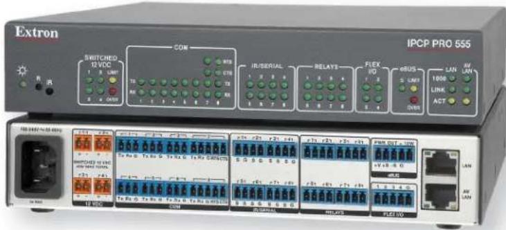
Figure 2. IPCP Pro 555
The IPCP Pro 555 (figure 2) is an example of an IPCP Pro control processor. It has a high-performance embedded web server, multiple bidirectional serial ports, relays, flex I/O ports, an Ethernet port, and AV LAN port, four independently switched 12 VDC outputs, and an eBUS port with dedicated 12 VDC output rated at 12 watts. The AV LAN port isolates AV devices from corporate networks, which keeps AV equipment from outside interference or intrusion, while allowing users to remotely control, monitor, and troubleshoot AV equipment. The IPCP Pro 555 is ideal for applications that require control for multiple devices within a large-scale AV system.
The eBUS connection not only provides a communication channel, but also supplies power to the endpoint devices. The amount of power that a control processor supplies varies from model to model. A typical IPCP Pro control processor is capable of powering up to eight* eBUS devices. Some eBUS accessories can be used to provide supplemental power when necessary to facilitate the connection for larger eBUS configurations.
*NOTE: Each device consumes a specific amount of power that is marked on the rear panel. It is important to calculate how many of the selected devices can be powered with the chosen control processor.
eBUS Endpoint Devices
eBUS endpoint devices are used with eBUS-enabled IP Link Pro control processors and provide flexible, cost-effective communications. A variety of these devices, with intuitive interfaces, are available to control common AV functions such as display power, audio level, source input selection, navigation, lighting, and projection screen control. Multiple eBUS devices can be combined with a single control processor to offer scalable AV control.
There are seven types of eBUS devices:
- US Gang Series — These wallplates are installed in US gang wall boxes. They have dual color backlit, hard buttons, rotary volume control and LED level indication for a contemporary look and feel while providing large buttons for ease of use in any lighting environment.
- Decorator-Style Wallplate Series — These wallplates are easily installed in US gang wall boxes. They have backlit, soft touch buttons for ease of use in low-light environments.
- EU Wall Frame Series — These 55 mm form factor panels mount into one-gang EU junction boxes. They have backlit, soft touch buttons for ease of use in low-light environments.
- MK Wall Frame Series — These 55 mm form factor panels mount into one-gang MK boxes and enclosures for use in the UK, Middle East, Singapore, and other regions using MK-type enclosures. They have backlit, soft touch buttons for ease of use in low-light environments.
- Cable Cubby Enclosure — This eBUS button panel combines AV system control with the convenience of an Extron Cable Cubby enclosure. It has a flip-up button panel integrated into the lid of the elegant metal enclosure.
- Rack Mount Panel — This 1U rack panel features dual-color backlit, hard buttons, rotary volume control and LED level indication. The large buttons provide ease of use in any lighting environment. The panel includes a four-port eBUS mini hub and four single space or two double space Architectural Adapter Plates (AAP).
- eBUS Control Module Series (ECM) — These eBUS control modules offer digital I/O and partition sensing to eBUS enabled control systems.
The Extron Web site (www.extron.com) provides a complete list of all the products in each category, and documentation that describes the function and installation of each device.
eBUS technology provides support for multiple endpoint devices. Each of these devices must have a unique Bus ID so that it can be discovered by the control processor. Use the six-pole DIP switch to set the address on each device to one of the 63 addresses supported by the IPCP Pro control processor.
NOTE: By default, the eBUS ID for each device category is set to a unique address from the factory. In basic systems like a small classroom with one button panel device, one control processor and one switcher, the user does not have to change the eBUS ID.
Most devices are equipped with two or four 4-pole female 3.5 mm captive screw eBUS connectors to easily connect multiple devices.
One example of an eBUS endpoint device is the EBP 106 D button panel (figure 3). The panel offers customizable, backlit, soft touch buttons and controls common AV functions such as display power, audio level and control, and input source selection.
You can order replacement or custom buttons for the decorator-style, EU, and MK series models, using the Custom Button Builder at www.extron.com.

Figure 3. EBP 106 D
eBUS Distribution Accessories
Distribution accessories provide a convenient connection point for eBUS wiring infrastructure. Examples include:
- EBDB MINI — This passive unit provides four passive eBUS connectors, providing ports for one eBUS input and up to three outputs connected in a star or hybrid configuration.
- EBDB (eBUS Distribution Block) — This passive unit provides ten parallel eBUS ports to facilitate the star and hybrid configurations.
- PS 1220EB – This active unit provides an eBUS 12VDC, 24 watt power supply for larger, more complex eBUS-based control systems. It is also a distribution block with six eBUS connectors, providing ports for one eBUS input and up to five outputs connected in a star or hybrid configuration.
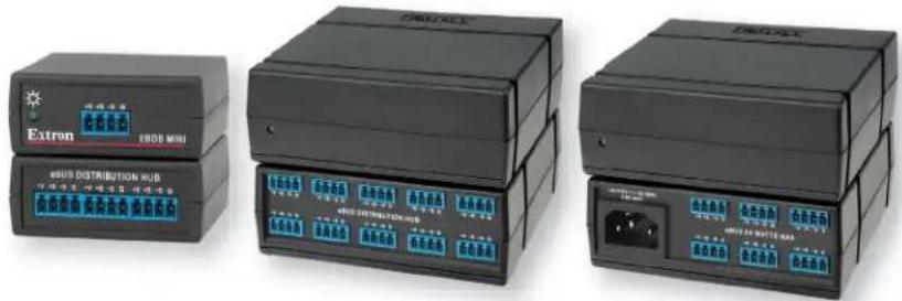
Figure 4. EBDB MINI (left), EBDB (center), and PS 1220EB (right)
eBUS System Configurations
eBUS systems can be categorized as basic or advanced, depending on the placement of devices in the overall topology. A basic system has a control processor and only one device. On the other hand, an advanced system can have a control processor, a switcher or a power injector, and multiple devices present in various combinations. The following section describes possible advanced device configurations:
• Daisy-Chain Configuration
- Star Configuration
• Hybrid Configuration
Daisy-Chain Configuration
All devices are equipped with one, two, or four sets of 4-pole female 3.5 mm captive screw connectors. One of these connectors is the input and the other is the output in a daisy-chain configuration. For devices with a single 4-pole female 3.5 mm captive screw connector, the connector is the input.
For devices with two or four 4-pole female 3.5 mm captive screw connectors, the usual drawback to the daisy-chain configuration is that if one device fails, all the devices that are downstream from that device also go offline. However, eBUS is designed so that, for devices with two or four sets of 4-pole connectors, the connectors are set up in parallel on the circuit board. If one device fails, downstream devices are not affected.
NOTE: If an endpoint device is disconnected from the daisy-chain, all downstream devices will also go offline.

flowchart
graph TD
    A["PCP Pro 555"] -->|RS-232| B["Flat Panel Display"]
    B --> C["EBP 105 D"]
    C -->|eBUS| D["EBP 106 D"]
    D -->|eBUS| E["EBP 105 D"]
    E -->|eBUS| F["EBP 106 D"]
    F -->|eBUS| G["EBP 105 D"]
    G --> H["BLU-ray Player"]
    C -->|eBUS| I["LAN"]
    I --> J["Ethernet"]
    J --> K["Lighting System"]
Figure 5. Daisy-chain Configuration
Star Configuration
A star configuration requires a distribution hub, which is always the central element of the star configuration. One of the connectors on the hub is the input and the others are outputs to achieve the star configuration.
An example of a distribution device is the EBDB eBUS distribution hub.

flowchart
graph TD
    subgraph_EBP_105_D["EBP 105 D"]
        A["LATCIP"] -->|eBUS| B["eBUS DISTRIBUTION HUB"]
        C["PC"] -->|eBUS| B
        D["USB"] -->|eBUS| B
    end

    subgraph_EBP_106_D["EBP 106 D"]
        E["EBP 105 D"] -->|eBUS| B
        F["LATCIP"] -->|eBUS| B
        G["PC"] -->|eBUS| B
        H["USB"] -->|eBUS| B
    end

    subgraph_IPCP_Pro_555["IPC P PRO 555"]
        I["Flat Panel Display"] -->|RS-232| J["IPC P PRO 555"]
        K["Blue-ray Player"] -->|IR| L["IPC P PRO 555"]
    end

    B -->|eBUS| B
    B -->|eBUS| B
    B -->|eBUS| B
    B -->|eBUS| B
    B -->|eBUS| B
    B -->|eBUS| B
    B -->|eBUS| B
    B -->|eBUS| B
    B -->|eBUS| B
    B -->|eBUS| B
    B -->|eBUS| B
    B -->|eBUS| B
Figure 6. Star Configuration
Hybrid Configuration
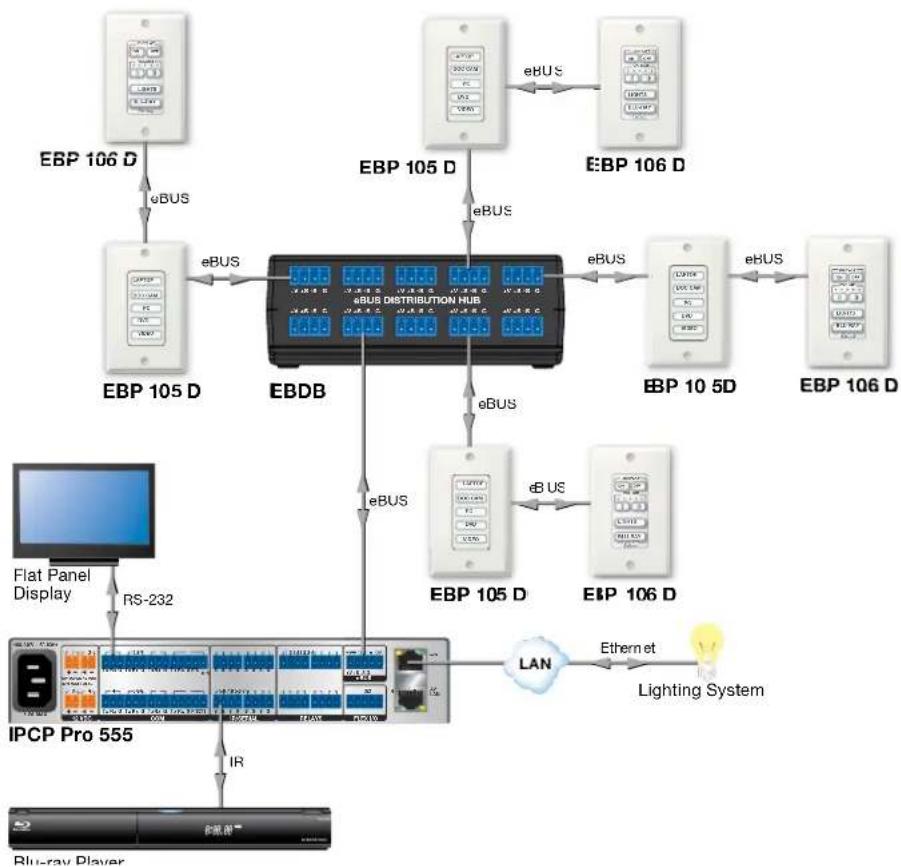
This type of configuration is achieved by using the combination of star and daisy-chain configurations. This topology makes use of the multiple eBUS connections present on devices and distribution accessories like EBDB.
flowchart
graph TD
    A["EBP 106 D"] -->|eBUS| B["EBB DB"]
    C["EBP 105 D"] -->|eBUS| B
    D["EBP 105 D"] -->|eBUS| B
    E["EBP 105 D"] -->|eBUS| B
    F["EBP 105 D"] -->|eBUS| G["EBDB"]
    H["EBP 105 D"] -->|eBUS| G
    I["EBP 105 D"] -->|eBUS| G
    J["EBP 105 D"] -->|eBUS| K["IPC P Pro 555"]
    L["EBP 105 D"] -->|eBUS| M["IPC P Pro 555"]
    N["EBP 105 D"] -->|eBUS| O["IPC P Pro 555"]
    P["EBP 105 D"] -->|eBUS| Q["IPC P Pro 555"]
    R["EBP 106 D"] -->|eBUS| S["IPC P Pro 555"]
    T["EBP 106 D"] -->|eBUS| U["IPC P Pro 555"]
    V["Flat Panel Display"] --> W["RS-232"]
    X["IPCP Pro 555"] --> Y["IR"]
    Z["LAN"] --> AA["Ethernet"]
    AA --> AB["Lighting System"]
    AC["Blue-ray Player"] --> AD["Blue Ray Player"]
Figure 7. Hybrid Configuration
NOTE: Whichever configuration is used, no more than eight devices can be connected, directly or indirectly through a hub or other accessory, to a single control processor.
eBUS Physical Description
This section provides an overview of the eBUS physical properties:
- Status Indication
• Physical Bus Topology
• eBUS Power Consumers and Providers
• Calculating Cable Length and Device Power Consumption
• eBUS Voltage Monitoring - Specifications
The eBUS system uses 3.5mm 4 pole captive screw connectors to provide power and communicate between eBUS control processors and the endpoint devices. Each device has an eBUS connection status indicator.
Status Indication
The eBUS endpoint devices use LEDs to provide feedback about the communication and power status for that device. This information is provided by one of three possible methods:
- A single monochrome (green) LED provides information by blinking at different speeds.
- A single bicolor LED lights to provide three possible colors: green, amber, and red.
• Three separate LEDs (green, amber, and red).
| Device Status Single LED | (monochrome) | Single LED (bi-color) | Three LEDs |
| No power, eBUS cable broken. Off Off All LEDs off | |||
| Device is receiving power and communicating correctly with the control processor. | Lights solidly Green | Green Green | |
| Device is receiving power but cannot communicate with the control processor. | Slow blink Amber | Amber Amber | |
| Device is receiving power and communicating with the control processor but there is an address conflict. | Fast blink Red | Red | |
An address conflict indicates that the BUS ID of one or more endpoint devices has been set incorrectly. The BUS ID is set using a six-pole DIP switch ito provide that device with a unique BUS ID (see eBUS ID Setup on page 17).
A maximum of eight devices can be connected to any control processor and the maximum combined cable run between eBUS devices and control processor is 1,000 feet. The maximum distance may be limited by the power output capability of the control processor or the power consumption of the devices. In situations with long cable runs or a large number of devices, an additional power provider may be required. (For more information about cable distances and power requirements, see Calculating Cable Length and Device Power Consumption on page 11).
Physical Bus Topology
Connector Layout
- Two connections provide power:
• +V (+12 V)
• G (ground and drain)
- Two connections (+S, -S) transmit and receive the communication signal.
All eBUS ports are connected in parallel, which allows each port to act as an input or an output for eBUS communication and power.
Recommended Cable
The recommended cable for eBUS connectivity is the Extron Serial Control/Audio Cable:
STP-20-2 (22-161-03, Non-Plenum)
STP-20-2P (22-163-03, Plenum).

Figure 8. Connector Wiring with Extron Serial Control Cable
Alternative Acceptable Cable
CAT 5e/6 cable can also be used to operate eBUS systems. It is commonly available and inexpensive:
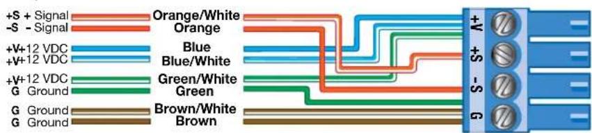
Figure 9. Connector Layout with CAT 5e/6 Cable
Alternatively, the CAT cable can be used with RJ-45 connectors and the Extron CSC 6 adapter.
NOTES: Extron recommends using serial control cable. The disadvantages of CAT cable include:
- All eight wires of the CAT cable must be connected in exactly the same way at both ends. If one of the wires is swapped, the signal is lost.
- All cable length specifications are based on STP20-2 serial control cable. You may not get the same performance from CAT cables.
eBUS Power Consumers and Providers
An eBUS device can be classified as either a consumer or a provider. A consumer, also called a passive device, is one that consumes energy and is incapable of adding power to the eBUS system. On the other hand, a provider, also called an active device, is one that is capable of adding power to the eBUS system.
All endpoint devices and the EBDB distribution hubs are consumers, as they do not add power to the system. All eBUS-enabled control processors and power supplies are considered providers.
NOTE: When a second power provider is added to the eBUS system, the group of devices powered by the first power source must be electrically isolated from the group of devices powered by the second source. Disconnect the +V wire from the cable run between the two groups so that each device receives a +V input from only one source.
Figure 10 shows a selection of eBUS power providers. For the complete range of power consumers and providers, see www.extron.com.

natural_image
Extron network device with IFCP PRO 350 ports and Ethernet ports (no visible text or labels beyond branding)
IPCP Pro 555
IPCP Pro 350
6 watts 12 watts

natural_image
Exterior view of a black electronic device with ports and connectors (no visible text or symbols)PS 1220EB
24 watts
Figure 10. eBUS Power Providers
Calculating Cable Length and Device Power Consumption
The maximum cable run for any eBUS topology is 1,000 feet (305 m). This distance is the cumulative run distance of all the cables in that topology. The actual maximum distance that can be powered by a single control processor depends on the control processor (see below), the number and type of the endpoint devices and the topology of the system (see eBUS System Configurations on page 5). Power injection may be required to achieve a total cable run of 1,000 feet.

flowchart
graph TD
    A["IPC P Pro 250 Control Processor"] -->|eBUS| B["EBDB Distribution Hub"]
    B -->|eBUS| C["EBP 105 EU"]
    B -->|eBUS| D["EBP 106 EU"]
    B -->|eBUS| E["EBP 105 EU"]
    B -->|eBUS| F["EBP 106 EU"]
    B -->|eBUS| G["EBP 105 EU"]
    B -->|eBUS| H["EBP 106 EU"]
Figure 11. Calculating Cable Length
To calculate the total cable length, add together the length of all the cables used in the system. In figure 11, the total cable length is the sum of A + B + C + D + E.
To calculate power consumption, use the maximum power consumption for each unit (when all the lights are lit). In the example above, the maximum power consumption for a single EBP 105 EU or EBP 106 EU unit is 1.5 watts, so the maximum power consumption for the entire system, with four units, is 6.0 watts.
The power consumption for each of the eBUS devices is shown on the back panel of each unit and can also be found in the Specifications (see page 16).
IPCP Pro Control Processors
The values below are for systems powered only by the control processor, with no additional power injection. If your system exceeds these values, additional power supplies or power injection are required (see Power Injection on the following page).
IPCP Pro 250, 255, 350 DR, 355 DR, 360, and PCS 1
- These control processors are able to provide power for up to 8 endpoint devices provided the total power consumption of all the devices does not exceed 6 watts.
- The recommended maximum total cable length for these control processors with a full power load (6 watts) is 250 feet. With longer cable runs, the devices furthest from the control processor may not receive sufficient power.
- The control processor may be able to power less devices (for example, three EBP 106 EU devices instead of four) at total cable distances that exceed 250 feet.
IPCP Pro 550 and 555
• These control processors are able to provide power for up to 8 endpoint devices provided the total power consumption of all the devices does not exceed 12 watts.
- The recommended maximum total cable length for these control processors with a full power load (12 watts) is 500 feet. With longer cable runs, the devices furthest from the control processor may not receive sufficient power.
- The control processor may be able to power less devices (for example, three EBP 106 EU devices instead of four) at total cable distances that exceed 500 feet.
Power Injection
If a system requires a total cable length or the total power consumption of all the devices that exceeds the limits shown on the previous page, you can use the PS 1210 P desktop power supply (see the next page) or the PS 1220EB (see page 14) to boost the system.
NOTE: When a second power provider is added to the eBUS system, the group of devices powered by the first power source must be electrically isolated from the group of devices powered by the second source. Disconnect the +V wire from the cable run between the two groups so that each device receives a +V input from only one source.
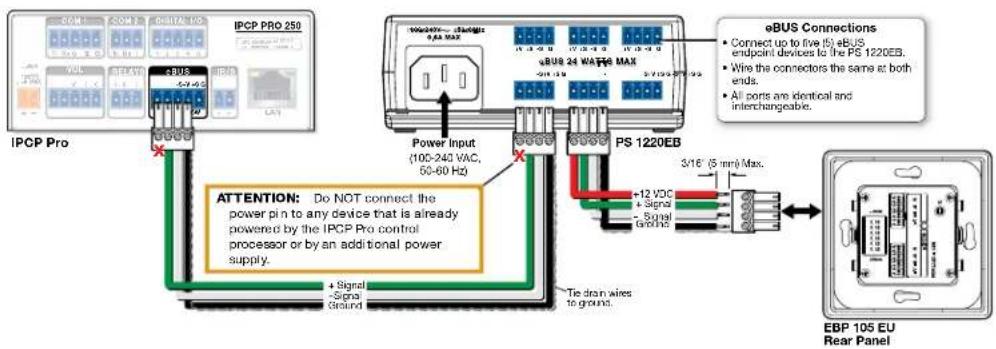
Figure 12. Adding a Power Provider to the eBUS System
PS 1210 P desktop power supply
- This power supply is able to provide power for up to 8 endpoint devices provided the total power consumption of all the devices does not exceed 12 watts.
- Even with this power supply, each control processor is limited to eight devices and a maximum total cable length of 1000 feet.
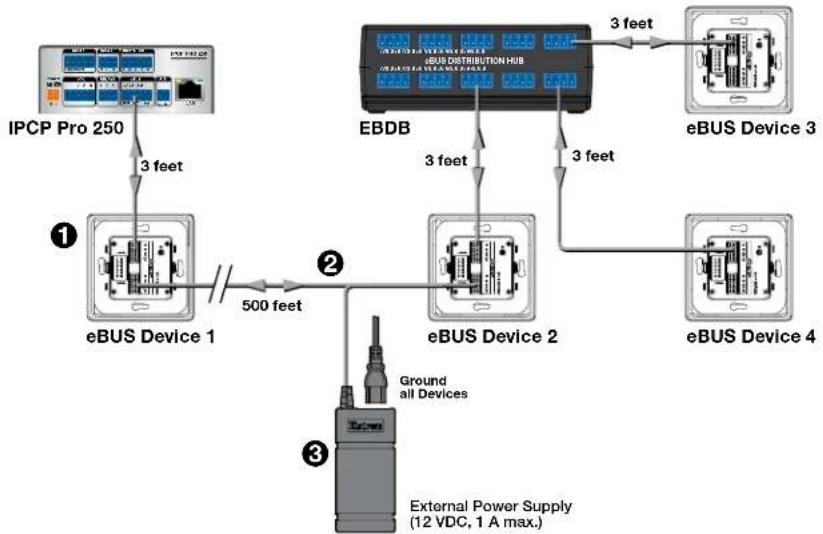
Figure 13 shows a typical eBUS star configuration. The total cable length of the system is 512 feet, which exceeds the maximum recommended cable length for a system powered by the IPCP Pro 250 alone. This can cause the voltage provided to devices 2, 3, and 4 to drop below 8.5 VDC. The PS 1210 P is used to provide additional power.
flowchart
graph TD
    A["IPC P Pro 250"] -->|3 feet| B["eBUS Device 1"]
    B -->|500 feet| C["②"]
    C -->|3 feet| D["EBDB"]
    D -->|3 feet| E["eBUS Device 3"]
    D -->|3 feet| F["eBUS Device 4"]
    C --> G["Ground all Devices"]
    C --> H["External Power Supply (12 VDC, 1 A max.)"]
Figure 13. With the PS 1210 P Power Supply
- eBUS device 1 (see figure 13, ①) is powered by the IPCP Pro 250. The remaining three devices are powered by the PS 1210 P power supply (③).
- The power supply can be connected to any of the devices it is powering (device 2, device 3, device 4, or the EBDB). In this example it is connected to device 2. Connect the +12V wire (smooth) to the +V input and the return wire (ridged) to the G input.
- Isolate the two power supplies in the system, by removing the +V wire from the cable connecting device 1 to device 2 (2). This cable must have only the +S, -S, and G wires.
PS 1220EB
- This power supply is able to provide power for up to 8 endpoint devices provided the total power consumption of all the devices does not exceed 24 watts.
- Even with this power supply, each control processor is limited to eight devices and a maximum total cable length of 1000 feet.
Figure 14 shows the same basic system as figure 13 (see the previous page). Instead of using a 12 V power supply, you can replace the EBDB with the PS 1220EB. This extends power an additional 500 feet, up to a maximum of 1000 feet, with up to 8 devices. The PS 1220EB also acts as a hub, allowing connections with up to six eBUS devices.

flowchart
graph TD
    A["IPC P Pro 250"] -->|3 feet| B["eBUS Device 1"]
    B -->|500 feet| C["PS 1220EB"]
    C -->|3 feet| D["eBUS Device 2"]
    D -->|3 feet| E["eBUS Device 3"]
    E -->|3 feet| F["eBUS Device 4"]
Figure 14. With the PS 1220EB Power Supply
- eBUS device 1 (see figure 14, ①) is powered by the IPCP Pro 250. The remaining three devices are powered by the PS 1220EB.
- To isolate the two parts of the system, remove the +V wire from the cable connecting device 1 to device 2 (②). This cable must have only the +S, -S, and G wires connected.
eBUS Voltage Monitoring
To function correctly, each endpoint device of the eBUS system must receive the proper voltage.
Extron Toolbelt software offers a diagnostic/utility tool that monitors the +V (12 VDC) line to show the power provided to each endpoint device. This allows system installers and administrators to determine where power injection is required.
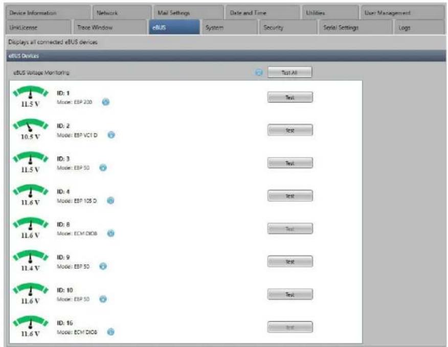
To access this tool, open Toolbelt and click the eBUS tab.
Voltage information for each endpoint device is provided. This information is color coded:
• The dial appears amber to indicate low voltage conditions.
• The dial appears green to indicate optimal voltage conditions.
- The dial appears red to indicate over-voltage conditions.
There are several other indicator colors. For a complete list, an explanation of each indicator, and troubleshooting assistance, see the Toolbelt Help File.
Specifications
This table provides a summary of eBUS specifications:
| Specification Details | |
| Maximum number of eBUS devices 8 — | each has a six-pole DIP switch to set the BUS ID. |
| Maximum total cable run 1000 ft (see Calculating Cable Length and Device Power Consumption on page 11). | |
| eBUS connector 3.5 mm, 4-pole captive screw | |
| System power requirements 12 VDC | Power available on eBUS port of the IPCP Pro control processor is product specific. |
| eBUS cables | |
| Recommended: 4-wire, Serial Control/Audio Cable Signal — 20 AWG | Extron STP20-2 (22-161-03, Non-Plenum)Extron STP20-2P (22-163-03, Plenum) |
| Acceptable: 8-wire (4 pairs), stranded core | CAT5e/6 — 22 or 23 AWG.It can be used with the Extron CSC 6 adapter. |
Configuration and Programming
This section provides information about
- eBUS ID Setup
- Software Support
- Firmware
eBUS ID Setup
For the control processor to be successfully configured, all endpoint devices must have unique eBUS IDs. Every device has a 6-pole DIP switch that is used to assign the IDs. The six DIP switches provide 64 addresses: One (000000) is reserved for the control processor and the remaining 63 can be used by the endpoint devices (see the table starting on the following page). Figure 15 provides an example of binary to decimal conversion:

| DIP Switch | ||||||
| 1 | 2 | 3 | 4 | 5 | 6 | |
| Position | Off | Off | Off | Off | On | Off |
| Decimal | 2^5=32 | 2^4=16 | 2^3=8 | 2^2=4 | 2^1=2 | 2^0=1 |
Figure 15. eBUS ID Setup
Add the decimal numbers for each of the DIP switches that are set to On to obtain the address of the device. In figure 15, only DIP switch #5 is on and the rest are off, which means the address for this device is 2.
To help integrators set eBUS IDs correctly, Extron provides an eBUS Address Calculator App, which can be accessed at www.extron.com.
This information is also provided in the Toolbelt Help File. The Toolbelt software also has a popup that assists installers to read and set DIP switch settings.
NOTES:
- Any address can be used except address 0 (binary: 000000), which is reserved (as the address of the control processor) and may not be used.
- Switch 1 (on the left) is the highest value (32, the most significant bit) and is labelled MSB.
- Switch 6 (on the right) is the lowest value (1, the least significant bit) and is labelled LSB.
• Up = on = 1, down = off = ∅
Setting eBUS ID Numbers
In the table below, a DIP switch setting shown as 0 is equivalent to 0ff. A DIP switch setting shown as 1 is equivalent to 0n.
NOTE: The eBUS ID number ∅ (Switch setting 000000) is reserved for the control processor and cannot be used by an eBUS endpoint device.
| DIP Switch Setting | Decimal Value 6 | DIP Switch Setting | Decimal Value | ||||||||||||||||||
| 1 | 2 | 3 | 4 | 5 | 6 | 1 | 2 | 3 | 4 | 5 | |||||||||||
| MSB | 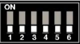 | LSB | ∅ | ∅ | ∅ | ∅ | ∅ | ∅ | 0 | MSB |  | LSB | ∅ | ∅ | 1 | 1 | 1 | 15 | |||
| MSB | 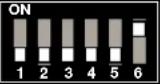 | LSB | ∅ | ∅ | ∅ | ∅ | ∅ | 1 | 1 | MSB | 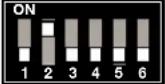 | LSB | ∅ | 1 | ∅ | ∅ | ∅ | 16 | |||
| MSB |  | LSB | ∅ | ∅ | ∅ | ∅ | 1 | ∅ | 2 | MSB |  | LSB | ∅ | 1 | ∅ | ∅ | 1 | 17 | |||
| MSB |  | LSB | ∅ | ∅ | ∅ | ∅ | 1 | 1 | 3 | MSB |  | LSB | ∅ | 1 | ∅ | ∅ | 1 | ∅ | 18 | ||
| MSB |  | LSB | ∅ | ∅ | ∅ | 1 | ∅ | ∅ | 4 | MSB |  | LSB | ∅ | 1 | ∅ | ∅ | 1 | 1 | 19 | ||
| MSB |  | LSB | ∅ | ∅ | ∅ | 1 | ∅ | 1 | 5 | MSB |  | LSB | ∅ | 1 | ∅ | 1 | ∅ | ∅ | 20 | ||
| MSB |  | LSB | ∅ | ∅ | ∅ | 1 | 1 | ∅ | 6 | MSB | 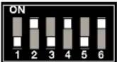 | LSB | ∅ | 1 | ∅ | 1 | ∅ | 1 | 21 | ||
| MSB |  | LSB | ∅ | ∅ | ∅ | 1 | 1 | 1 | 7 | MSB | 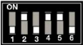 | LSB | ∅ | 1 | ∅ | 1 | 1 | ∅ | 22 | ||
| MSB |  | LSB | ∅ | ∅ | 1 | ∅ | ∅ | ∅ | 8 | MSB |  | LSB | ∅ | 1 | ∅ | 1 | 1 | 1 | 23 | ||
| MSB |  | LSB | ∅ | ∅ | 1 | ∅ | ∅ | 1 | 9 | MSB | 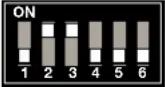 | LSB | ∅ | 1 | 1 | ∅ | ∅ | ∅ | 24 | ||
| MSB |  | LSB | ∅ | ∅ | 1 | ∅ | 1 | ∅ | 10 | MSB |  | LSB | ∅ | 1 | 1 | ∅ | ∅ | 1 | 25 | ||
| MSB | 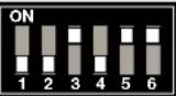 | LSB | ∅ | ∅ | 1 | ∅ | 1 | 1 | 11 | MSB |  | LSB | ∅ | 1 | 1 | ∅ | 1 | ∅ | 26 | ||
| MSB |  | LSB | ∅ | ∅ | 1 | 1 | ∅ | ∅ | 12 | MSB | 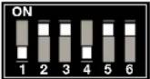 | LSB | ∅ | 1 | 1 | ∅ | 1 | 1 | 27 | ||
| MSB |  | LSB | ∅ | ∅ | 1 | 1 | ∅ | 1 | 13 | MSB | 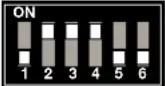 | LSB | ∅ | 1 | 1 | 1 | ∅ | ∅ | 28 | ||
| MSB |  | LSB | ∅ | ∅ | 1 | 1 | 1 | ∅ | 14 | MSB | 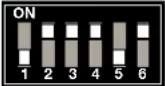 | LSB | ∅ | 1 | 1 | 1 | ∅ | 1 | 29 | ||
| DIP Switch Setting | Decimal Value | DIP Switch Setting | Decimal Value | ||||||||||||||||||
| 1 | 2 | 3 | 4 | 5 | 6 | 1 | 2 | 3 | 4 | 5 | 6 | ||||||||||
| MSB | 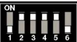 | LSB | ∅ | 1 | 1 | 1 | 1 | ∅ | 30 | MSB | 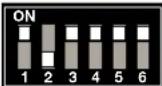 | LSB | 1 | ∅ | 1 | 1 | 1 | 47 | |||
| MSB |  | LSB | ∅ | 1 | 1 | 1 | 1 | 1 | 31 | MSB |  | LSB | 1 | 1 | ∅ | ∅ | ∅ | 48 | |||
| MSB |  | LSB | 1 | ∅ | ∅ | ∅ | ∅ | ∅ | 32 | MSB | 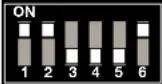 | LSB | 1 | 1 | ∅ | ∅ | 1 | 49 | |||
| MSB |  | LSB | 1 | ∅ | ∅ | ∅ | ∅ | 1 | 33 | MSB | 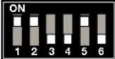 | LSB | 1 | 1 | ∅ | ∅ | 1 | ∅ | 50 | ||
| MSB |  | LSB | 1 | ∅ | ∅ | ∅ | 1 | ∅ | 34 | MSB |  | LSB | 1 | 1 | ∅ | ∅ | 1 | 1 | 51 | ||
| MSB |  | LSB | 1 | ∅ | ∅ | ∅ | 1 | 1 | 35 | MSB |  | LSB | 1 | 1 | ∅ | 1 | ∅ | ∅ | 52 | ||
| MSB |  | LSB | 1 | ∅ | ∅ | 1 | ∅ | ∅ | 36 | MSB | 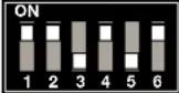 | LSB | 1 | 1 | ∅ | 1 | ∅ | 1 | 53 | ||
| MSB |  | LSB | 1 | ∅ | ∅ | 1 | ∅ | 1 | 37 | MSB | 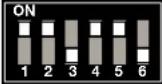 | LSB | 1 | 1 | ∅ | 1 | 1 | ∅ | 54 | ||
| MSB |  | LSB | 1 | ∅ | ∅ | 1 | 1 | ∅ | 38 | MSB |  | LSB | 1 | 1 | ∅ | 1 | 1 | 1 | 55 | ||
| MSB |  | LSB | 1 | ∅ | ∅ | 1 | 1 | 1 | 39 | MSB | 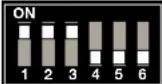 | LSB | 1 | 1 | 1 | ∅ | ∅ | ∅ | 56 | ||
| MSB |  | LSB | 1 | ∅ | 1 | ∅ | ∅ | ∅ | 40 | MSB |  | LSB | 1 | 1 | 1 | ∅ | ∅ | 1 | 57 | ||
| MSB | 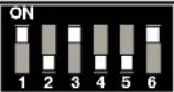 | LSB | 1 | ∅ | 1 | ∅ | ∅ | 1 | 41 | MSB |  | LSB | 1 | 1 | 1 | ∅ | 1 | ∅ | 58 | ||
| MSB |  | LSB | 1 | ∅ | 1 | ∅ | 1 | ∅ | 42 | MSB |  | LSB | 1 | 1 | 1 | ∅ | 1 | 1 | 59 | ||
| MSB |  | LSB | 1 | ∅ | 1 | ∅ | 1 | 1 | 43 | MSB | 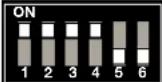 | LSB | 1 | 1 | 1 | 1 | ∅ | ∅ | 60 | ||
| MSB |  | LSB | 1 | ∅ | 1 | 1 | ∅ | ∅ | 44 | MSB |  | LSB | 1 | 1 | 1 | 1 | ∅ | 1 | 61 | ||
| MSB |  | LSB | 1 | ∅ | 1 | 1 | ∅ | 1 | 45 | MSB |  | LSB | 1 | 1 | 1 | 1 | 1 | ∅ | 62 | ||
| MSB | 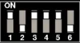 | LSB | 1 | ∅ | 1 | 1 | 1 | ∅ | 46 | MSB | 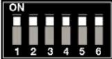 | LSB | 1 | 1 | 1 | 1 | 1 | 1 | 63 | ||
Software Support
The Extron eBUS Control System is flexible and allows for both configurable and programmable control.
To set up a system by configuration, use Global Configurator Plus and Professional.
Configuring eBUS-enabled systems is as easy as adding control processors, devices, and drivers in the configuration software and then dragging and dropping commands onto the available buttons.
Advanced configuration elements like monitors and schedules are also available, where various operations can be performed based on the feedback received from the controlled devices or at scheduled times.
To set up a system by programming, use Global Scripter. Programming eBUS-enabled systems allows more granular and specific control over the system.
The following Extron software supports eBUS:
Global Configurator Plus and Professional
Global Configurator Plus and Professional is powerful configuration software for AV control systems. It allows both on-line and off-line configuration. On-line configuration is useful when engineers or technicians are at the job site and all endpoint devices can be discovered by the eBUS-enabled control processor. Off-line configuration is useful when technicians are creating a configuration file before physically setting up the control processor and endpoint devices to communicate with each other.
For more information, see the Global Configurator Plus and Professional Help file. Open the latest version of Global Configurator Plus and Professional, click on the Help tab, and then click on Global Configurator Plus and Professional Help or press
Global Scripter
Global Scripter is an integrated development environment for Extron control systems programming. It allows control scripts to be written and uploaded to an eBUS-enabled control processor.
For more information, see the Global Scripter Help file. Open the latest version of Global Scripter, click the Help tab, and then click Global Scripter Help or press
GlobalViewer Enterprise
GlobalViewer Enterprise is a server-based AV resource management software program. For more information, see the GlobalViewer Enterprise Help file. Open the latest version of GVE and click the ? icon in the upper right corner.
Toolbelt
Toolbelt is a management and troubleshooting utility for Extron Pro Series control products. For more information, see the Toolbelt Help file. Open the latest version of Toolbelt, click the Help tab, and then click on Toolbelt Help or press
Extron Control
Extron Control is an AV control system app that gives users complete access to Extron control systems directly from mobile devices using the iOS or Android operating systems or from the web.
Firmware
All eBUS devices must have firmware that is compatible with the control processor. To ensure this, the eBUS device firmware is managed automatically by the control processor. Updates to the configuration file or product firmware are pushed to eBUS devices via the IPCP Pro control processor.
When the system is powered on after an eBUS device is connected to the control processor, the processor checks the firmware version that is installed on the eBUS device and, if necessary, updates the endpoint device firmware to a compatible version. While an eBUS device is receiving the firmware update, the front panel LED of the IPCP control processor flashes slowly.
If you add a new eBUS device to an existing system, the factory-installed firmware on the device may be more recent than the control processor firmware. In that case, an earlier version of the firmware is pushed to the eBUS device to ensure that it is compatible with the control processor.
When you update the control processor firmware, the processor checks all the attached eBUS devices and, if necessary, automatically updates their firmware. It is not necessary to upgrade the firmware for eBUS-enabled control processors each time Extron introduces a new category of endpoint devices.
For more information about updating IPCP Pro control processor firmware, see the help files for Toolbelt and Global Configurator Plus and Professional at www.extron.com.
Reset Button
If the firmware is not installed correctly, it can be reset in a two step process.
In the first step, use the Reset button to reset the endpoint device firmware to the factory installed version:
- Locate the Reset button for your device (see the appropriate setup guide at www.extron.com).
- Disconnect the eBUS cable that is providing power.
- Reconnect the power and, at the same time, press and hold down the Reset button.
- Release the Reset button 1 second after reconnecting power.
During the reset process, front panel buttons of the reset device are not lit.
When the Green status LED lights, the reset process is complete, and the EBP is functioning normally.
Once the factory-installed firmware is installed, the second step occurs automatically:
- The control processor checks the firmware installed on the endpoint device.
- If the factory installed firmware compatible with the control processor, nothing further happens.
If an incompatible firmware version is detected, the control processor updates the endpoint firmware to a compatible version, as described in the previous section.
File Types
- The Global Configurator file must be in the .gcpro format.
- Driver files may be required while configuring eBUS-enabled control processors.
- The file type for infrared-controlled devices is .eir.
- The file type for serial-controlled devices is .pke.
- The file type for Ethernet-controlled devices is .pkn.
- The file type for eBUS endpoint device firmware is .s19.
Setup
This section of the guide provides the following information about setting up the system:
- Initial Setup
- Obtaining Communications
- Updating the eBUS System
Initial Setup
- Disconnect power from all eBUS endpoint devices in the control system.
- Refer to the specification sheet for each endpoint device to calculate the power needs for your system and determine whether additional power supplies are needed.
- Assigne unique eBUS ID for all endpoint devices (see Setting eBUS ID Numbers on page 18).
- Choose a star, daisy chain, or hybrid configuration for your system (see eBUS System Configurations on page 5).
NOTES:
- If power must be passed to the next unit, connect all six conductors (+12 VDC, signal+, signal-, two drain wires, and ground).
- If power is not passed to the next unit (because it is powered by a separate power supply), connect only the signal+, signal-, two drain wires, and ground conductors are wired. Do not connect the 12 VDC conductor.
If there are any problems with the system once it has been set up, see the Troubleshooting section on page 24.
Obtaining Communications
- Power up the eBUS-enabled control processor and any other eBUS power providers in the system.
- Check the communication between the control processor and the endpoint devices (see Status Indication on page 8).
NOTE: Communication issues arising from ID conflicts can be diagnosed from the default web page of the eBUS-enabled control processor.
Updating the eBUS System
Replacing an eBUS-enabled Control Processor in an Established System
- Ensure the existing configuration file has been saved.
- Mount the replacement control processor in a suitable location.
- Connect cables and power to the processor (see the user guide for the control processor at www.extron.com).
- Re-load the configuration file to the replacement control processor.
NOTES:
- Re-configuration is not required if the new control processor is the same model as the one being replaced.
- If the new control processor is a different model from the one being replaced, the GCP project must be changed, rebuilt, and uploaded to the new processor.
- It is not necessary to power cycle the system.
Adding a New Endpoint Device to an Established System
- Set a unique device eBUS ID (see eBUS ID Setup on page 17).
- Mount the device (see the setup guide for the product at www.extron.com).
- Connect eBUS cables from the control processor or the eBUS system to the device.
- Use the eBUS Voltage Monitoring diagnostic/utility tool to verify that the voltage level at each endpoint is within the optimal range (see eBUS Voltage Monitoring on page 15).
NOTES:
- If you are using GCP, the project must be changed, rebuilt, and uploaded to the control processor.
- If you are using Global Scripter, add the new device in the computer code.
- It is not necessary to power cycle the system.
Replacing an Endpoint Device in an Established System
- Set the eBUS ID of the replacement device to match the ID of the unit it is replacing (see eBUS ID Setup on page 17).
- Mount the replacement device in a suitable location.
- Connect eBUS cables to the device.
NOTES:
- If the new eBUS device is the same model as the one being replaced, you do not need to rebuild an upload the GCP project or change the Global Scripter code.
- If the new eBUS device is a different model from the one being replaced, the GCP project must be changed, rebuilt, and uploaded to the new processor or the model must be changed in the Global Scripter code.
- It is not necessary to power cycle the system.
Troubleshooting
This section provides four examples of the most common problems that can arise and provides one or more solutions.
• Devices Are Not Getting Enough Power (Cable Run is Too Long)
• Devices Are Not Getting Enough Power (Too Many Devices)
- Connectors Are Not Wired Correctly
• There is an eBUS ID Conflict
- Other Issues
Devices Are Not Getting Enough Power (Cable Run is Too Long)
flowchart
graph TD
    A["IPC P Pro 250"] -->|3 feet| B["eBUS Device 1"]
    B -->|500 feet| C["eBUS Device 2"]
    C -->|3 feet| D["EBDB"]
    D -->|3 feet| E["eBUS Device 3"]
    E -->|3 feet| F["eBUS Device 4"]
Figure 16. Cable Run is Too Long
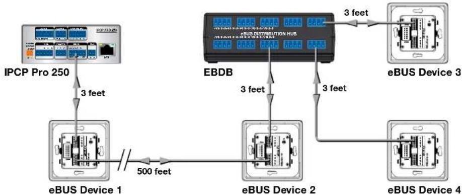
In this first example, the total cable run is 512 feet (3 + 500 + 3 + 3 + 3). This exceeds the recommended maximum cable length for the IPCP Pro 250 (250 feet), which can lead to a drop in the voltage provided to devices 2, 3, and 4 to below 8.5 VDC.
The maximum power consumption by the four button panels is 6 watts (4 x 1.5 watts). This does not exceed the maximum power available from the IPCP Pro 250, which is 6 watts.
Symptoms
- The eBUS devices 1 and 2 (closest to the IPCP Pro 250) work correctly but devices 3 and 4 do not.
- When any one panel is removed, the other three work normally.
- When the voltage is monitored using Toolbelt (see eBUS Voltage Monitoring on page 15), the voltage between the +V and G wires of the eBUS cable is 8.0 VDC. It should be at least 8.5 VDC.
Solution
The recommended minimum voltage is 8.5 V. The measured voltage shows that too much voltage has been lost over the long cable run. This is supported by removing one panel and observing that the three remaining panels all work normally when less power is being drawn. Replace the EBDB with a PS 1220EB. This injects the additional power required to overcome the power dropped over the long cable run and all four button panels can function normally. eBUS devices can receive power from only one source, either the control processor or the power supply. The panels receiving power from the control processor must be isolated from the panels receiving power from the power supply.
- eBUS device 1 (see figure 17, ①) is powered by the IPCP Pro 250. The remaining three devices are powered by the PS 1220EB power supply.
- To isolate the two parts of the system that are receiving power from different sources, remove the +V wire from the cable connecting device 1 to device 2 (2). This cable must have only the +S, -S, and G wires.

flowchart
graph TD
    A["IPC P Pro 250"] -->|3 feet| B["eBUS Device 1"]
    B -->|500 feet| C["PS 1220EB"]
    C -->|3 feet| D["eBUS Device 2"]
    D -->|3 feet| E["eBUS Device 3"]
    E -->|3 feet| F["eBUS Device 4"]
Figure 17. Devices are Now Getting Sufficient Power
Devices Are Not Getting Enough Power (Too Many Devices)

flowchart
graph TD
    A["eBUS Device 5"] -->|3 feet| B["eBUS Device 6"]
    B -->|3 feet| C["EBDB"]
    C -->|3 feet| D["eBUS Device 7"]
    D -->|3 feet| E["eBUS Device 8"]
    F["IPC P Pro 250"] -->|3 feet| G["eBUS Device 1"]
    G -->|3 feet| H["eBUS Device 2"]
    H -->|3 feet| I["eBUS Device 3"]
    I -->|3 feet| J["eBUS Device 4"]
    J -->|3 feet| K["eBUS Device 5"]
Figure 18. Too Many Devices
In this example the total cable run is 27 feet (9 x 3 feet), which below the recommended maximum of 250 feet with a full power load, so all the eBUS devices should be receiving at least the minimum required voltage (8.5 VDC).
The maximum power consumption by the eight panels is 12 watts (8 x 1.5 watts), which exceeds the maximum power available from the IPCP Pro 250, which is 6 watts.
Symptoms
• The button panels do not work.
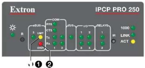
- The yellow (Limit) or red (Overload) LED on the front panel of the IPCP Pro 250 is lit solidly. The yellow (Limit) LED (figure 19, ①) lights solidly when the power drawn by eBUS system is at the maximum threshold for the control processor.
The red (Overload) LED (2) lights solidly when the power drawn by eBUS system exceeds the maximum threshold for the control processor. When this occurs, power to the eBUS is shut down.
flowchart
graph TD
    A["Extron"] --> B["eBUS"]
    B --> C["S"]
    B --> D["LIMIT"]
    B --> E["R"]
    B --> F["OVER"]
    B --> G["COM"]
    G --> H["RTS"]
    G --> I["CTS"]
    G --> J["Tx"]
    G --> K["Rx"]
    G --> L["1"]
    G --> M["2"]
    G --> N["IR/S"]
    G --> O["I/O"]
    G --> P["RELAYS"]
    G --> Q["1"]
    G --> R["2"]
    G --> S["IR"]
    G --> T["1000"]
    G --> U["LINK"]
    G --> V["ACT"]
Figure 19. IPCP Pro 250 Limit (①) and Overload (②) LEDs
Solutions
Replace the EBDB with a PS 1220EB (see figure 20). The first four button panels use 6 watts and can be powered by the IPCP Pro 250. The PS 1220EB injects the additional power required for the other four button panels to function normally.
eBUS devices can receive power from only one source, either the control processor or the power supply. The panels receiving power from the control processor must be isolated from the panels receiving power from the power supply.
- eBUS devices 1, 2, 3, and 4 are powered by the IPCP Pro 250. The remaining four devices are powered by the PS 1220EB power supply.
- To isolate the two parts of the system that are receiving power from different sources, remove the +V wire from the cable connecting device 4 to the PS 1220EB (1). This cable must have only the +S, -S, and G wires connected.

flowchart
graph TD
    A["eBUS Device 5"] -->|3 feet| B["eBUS Device 6"]
    B -->|3 feet| C["PS 1220EB"]
    C -->|3 feet| D["eBUS Device 7"]
    D -->|3 feet| E["eBUS Device 8"]
    F["IPC P Pro 250"] -->|3 feet| G["eBUS Device 1"]
    G -->|3 feet| H["eBUS Device 2"]
    H -->|3 feet| I["eBUS Device 3"]
    I -->|3 feet| J["eBUS Device 4"]
    J -->|3 feet| K["PS 1220EB"]
Figure 20. Devices are Now Getting Sufficient Power
NOTE: There are two additional solutions:
- Instead of adding a power injector, keep the EBDB and replace the IPCP Pro 250 with the IPCP Pro 550 control process. This can provide up to 12 watts, which is sufficient to power all eight button panels without the need for power injection.
- Instead of adding the PS 1220EB, keep the EBDB and add a PS1210 desktop power supply to provide power.
Connectors Are Not Wired Correctly

flowchart
graph LR
    A["IPC P Pro 250"] -->|3 feet| B["eBUS Device 1"]
    B -->|3 feet| C["eBUS Device 2"]
    C -->|3 feet| D["eBUS Device 3"]
    B --> E["+V +12 VDC"]
    B --> F["+S + Signal"]
    B --> G["-S - Signal"]
    B --> H["G Ground"]
    C --> I["+V +V"]
    C --> J["-S - S"]
    C --> K["G G"]
    D --> L["+V +V"]
    D --> M["-S - S"]
    D --> N["G G"]
    style A fill:#f9f,stroke:#333
    style B fill:#ccf,stroke:#333
    style C fill:#ccf,stroke:#333
    style D fill:#ccf,stroke:#333
Figure 21. Incorrect Wiring
In this example, the total cable length is 9 feet and the total power requirement is 4.5 watts, both within the capabilities of the IPCP Pro 250.
Symptoms
• The first button panel works correctly but the second and third do not.
- On the back of the first button panel, the green LED (see figure 21, ①) is lit solidly. This indicates that this unit is receiving power and is communicating with the IPCP Pro 250.
- On the back of both the second and third button panels, the green LED is flashing slowly (older models) or the amber LED is solidly lit (newer models), indicating a BUS communication error.
Solution
Since the first panel works correctly but the second and third panels do not, there is a problem with the wiring between the first and second panels.
The LEDs on the backs of the second and third panels are indicating that the units are powered correctly but not communicating with the IPCP Pro 250. This suggests that there may be a problem with the signal wires.
As shown in figure 22, the wiring from the IPCP Pro 250 to eBUS Device 1 is correct but the wiring between eBUS Device 1 and eBUS Device 2 is incorrect: the +S and -S wires are switched. As a result, neither eBUS device 2 nor eBUS device 3 is receiving correct signals and neither functions correctly.
NOTE: The connection between the second and third panels is wired correctly. However, because the signal being input to the second panel is incorrect, all panels downstream from the second panel also receive incorrect signals and are not be able to communicate with the IPCP Pro 250.
The problem is corrected by switching the green (+S) wire and the white (-S) wire on the cable input to the second button panel.
There is an eBUS ID Conflict

flowchart
graph LR
    A["IPC P Pro 250"] -->|3 feet| B["eBUS Device 1"]
    B -->|3 feet| C["eBUS Device 2"]
    C -->|3 feet| D["eBUS Device 3"]
    style A fill:#f9f,stroke:#333
    style B fill:#ccf,stroke:#333
    style C fill:#ccf,stroke:#333
    style D fill:#ccf,stroke:#333
Figure 22. ID Conflict
In this example, the total cable length is 9 feet and the total power requirement is 4.5 W, both within the capabilities of the IPCP Pro 250.
Symptoms
- eBUS device 2 works correctly but devices 1 and 3 do not.
- The green LED (figure 22 1) on the back of eBUS device 2 lights solidly, indicating that this unit has no problems.
- The green LED on the back of both devices 1 and 3 flash quickly (older models) or the red LED lights solidly (more recent models), indicating a BUS ID conflict.
- The green Signal (S) LED on the front panel of the IPCP Pro 250 (figure 23, ①) flashes quickly, also indicating a BUS ID conflict.
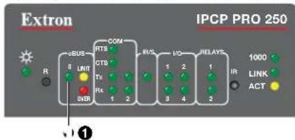
Figure 23. IPCP Pro 250 Front Panel
Solution
The LEDs on the first and third panels and on the IPCP Pro 250 indicate that there is an ID conflict. Check the IDs for each of the panels. Figure 22 shows that the first and third button panels both have IDs of 6. All devices connected to the same control processor must have unique IDs (see Setting eBUS ID Numbers on page 18).
It is likely that one of the eBUS ID numbers was set incorrectly and does not correspond to the value that was assigned when the system was set up. Check which values were assigned to the eBUS devices during configuration (GCP) or programming (Global Scripter) and adjust the DIP switches appropriately.
Alternatively, the system was incorrectly set up. Reset the eBUS ID number for device 1 or 3 and use GCP or Global Scripter to assign the new ID numbers to the control processor.
NOTES:
- GCP and GS do not allow you to build a system containing two or more eBUS devices that have the same BUS ID.
- Conflicts can arise when an eBUS device is physically replaced with a new device that has an incorrect BUS ID. This can be detected by Toolbelt.
- If an eBUS device is replaced with an identical device that has the same BUS ID, there may not be a need to reconfigure the system with GCP. Otherwise, after changing the DIP switches to change the BUS ID, the system must be reconfigured in GCP for control processor to recognize the eBUS device.
Other Issues
If there are any other problems with your system, start by checking the diagnostic LED conditions on the button panels and IPCP Pro control processor.
- Power up the IPCP Pro control processor and any eBUS power providers present on the bus.
- Check the communication between control processor and the devices using the eBUS diagnostic LED on each device.
Button Panel Diagnostic LED Conditions
The eBUS endpoint devices use LEDs to provide feedback about the communication and power status for that device. This information is provided by one of three possible methods:
- A single monochrome (green) LED provides information by blinking at different speeds.
- A single bicolor LED lights to provide three possible colors: green, amber, and red.
- Three separate LEDs (green, amber, and red).
| Device Status Single LED | (monochrome) | Single LED (bicolor) | Three LEDs |
| No power, eBUS cable broken. Off Off All LEDs off | |||
| Device is receiving power and communicating correctly with the control processor. | Lights solidly Green | Green Green | |
| Device is receiving power but cannot communicate with the control processor. | Slow blink Amber | Amber | |
| Device is receiving power and communicating with the control processor but there is an address conflict. | Fast blink Red | Red | |
Control Processor LED Conditions
The control processor eBUS LED (see figure 23, 1 on the previous page) provides the following information:
• LED is not lit — No power is present or no eBUS devices are present on the BUS.
• LED is flashing slowly - An eBUS device is receiving a firmware update.
• LED is flashing quickly — An eBUS ID conflict is present within the system.
- LED is lit solid — Power is present with confirmed communication and no eBUS ID conflicts.
Other Possible Issues
Problem communicating with the control processor
The control processor is not receiving power — Check the green Power LED on the control processor. If that is not lit, there is no power connected.
Ethernet connection not established — Ensure the Ethernet cable is correctly wired and connected. Try using crossover Ethernet cable and static IP addresses on the PC and control processor.
NOTE: Communication between the control processor and EBPs is via eBUS and is not affected by loss of an Ethernet connection.
Firmware issues — Occasionally there is an error updating firmware. If this happens use the Reset button to reinstall the firmware (see Reset Button on page 21).
Extron Warranty
Extron Electronics warrants this product against defects in materials and workmanship for a period of three years from the date of purchase. In the event of malfunction during the warranty period attributable directly to faulty workmanship and/or materials, Extron Electronics will, at its option, repair or replace said products or components, to whatever extent it shall deem necessary to restore said product to proper operating condition, provided that it is returned within the warranty period, with proof of purchase and description of malfunction to:
USA, Canada, South America, and Central America:
Extron Electronics
1230 South Lewis Street
Anaheim, CA 92805
U.S.A.
Asia:
Extron Electronics Asia Pte. Ltd.
135 Joo Seng Road, #04-01
PM Industrial Bldg.
Singapore 368363
Singapore
Japan:
Extron Electronics, Japan
Kyodo Building, 16 Ichibancho
Chiyoda-ku, Tokyo 102-0082
Japan
Europe:
Extron Europe
Hanzeboulevard 10
3825 PH Amersfoort
The Netherlands
China:
Extron China
686 Ronghua Road
Songjiang District
Shanghai 201611
China
Middle East:
Extron Middle East
Dubai Airport Free Zone
F13, PO Box 293666
Dubai, United Arab Emirates
Africa:
Extron South Africa
South Tower
160 Jan Smuts Avenue
Rosebank 2196, South Africa
This Limited Warranty does not apply if the fault has been caused by misuse, improper handling care, electrical or mechanical abuse, abnormal operating conditions, or if modifications were made to the product that were not authorized by Extron.
NOTE: If a product is defective, please call Extron and ask for an Application Engineer to receive an RA (Return Authorization) number. This will begin the repair process.
USA: 714.491.1500 or 800.633.9876
Asia: 65.6383.4400
Europe: 31.33.453.4040 or 800.3987.6673
Japan: 81.3.3511.7655
Africa: 27.11.447.6162
Middle East: 971.4.299.1800
Units must be returned insured, with shipping charges prepaid. If not insured, you assume the risk of loss or damage during shipment. Returned units must include the serial number and a description of the problem, as well as the name of the person to contact in case there are any questions.
Extron Electronics makes no further warranties either expressed or implied with respect to the product and its quality, performance, merchantability, or fitness for any particular use. In no event will Extron Electronics be liable for direct, indirect, or consequential damages resulting from any defect in this product even if Extron Electronics has been advised of such damage.
Please note that laws vary from state to state and country to country, and that some provisions of this warranty may not apply to you.

- Safety Instructions • English
- Trademarks
- Registered Trademarks®
- Registered Service Mark (SM) : S3 Service Support Solutions
- Trademarks TM
- FCC Class A Notice
- NOTE:
- UL Notice
- Conventions Used in this Guide
- Notifications
- ATTENTION:
- Software Commands
- Specifications Availability
- Extron Glossary of Terms
- Contents
- Introduction...... 1
- eBUS System Configurations......5
- eBUS Physical Description 8
- Configuration and Programming......17
- Setup....22
- Troubleshooting 24
- Introduction
- Description
- eBUS Features
- eBUS-enabled Control Processors
- eBUS Endpoint Devices
- eBUS Distribution Accessories
- eBUS System Configurations
- Daisy-Chain Configuration
- Star Configuration
- Hybrid Configuration
- eBUS Physical Description
- Status Indication
- Physical Bus Topology
- Connector Layout
- Recommended Cable
- Alternative Acceptable Cable
- eBUS Power Consumers and Providers
- Calculating Cable Length and Device Power Consumption
- IPCP Pro Control Processors
- IPCP Pro 250, 255, 350 DR, 355 DR, 360, and PCS 1
- IPCP Pro 550 and 555
- Power Injection
- PS 1210 P desktop power supply
- PS 1220EB
- eBUS Voltage Monitoring
- Specifications
- Configuration and Programming
- eBUS ID Setup
- NOTES:
- Setting eBUS ID Numbers
- Software Support
- Global Configurator Plus and Professional
- Global Scripter
- GlobalViewer Enterprise
- Toolbelt
- Extron Control
- Firmware
- Reset Button
- File Types
- Setup
- Initial Setup
- Obtaining Communications
- Updating the eBUS System
- Replacing an eBUS-enabled Control Processor in an Established System
- Adding a New Endpoint Device to an Established System
- Replacing an Endpoint Device in an Established System
- Troubleshooting
- Devices Are Not Getting Enough Power (Cable Run is Too Long)
- Symptoms
- Solution
- Devices Are Not Getting Enough Power (Too Many Devices)
- Solutions
- NOTE: There are two additional solutions:
- Connectors Are Not Wired Correctly
- There is an eBUS ID Conflict
- Other Issues
- Button Panel Diagnostic LED Conditions
- Control Processor LED Conditions
- Other Possible Issues
- Problem communicating with the control processor
- Extron Warranty
- USA, Canada, South America, and Central America:
- Asia:
- Japan:
- Europe:
- China:
- Middle East:
- Africa:
Brand : Extron
Model : EBP VC1 EU
Category : Matériel électronique de contrôle