
vMON-270-8K - Screen Wohler - Free user manual and instructions
Find the device manual for free vMON-270-8K Wohler in PDF.

| Product Type | Professional 8K Video Monitor |
| Display Size | 27 inches |
| Resolution | 7680 x 4320 (8K UHD) |
| Aspect Ratio | 16:9 |
| Brightness | 500 cd/m² |
| Contrast Ratio | 1000:1 |
| Viewing Angles | 178° horizontal / 178° vertical |
| Video Inputs | 2x 12G-SDI, 1x HDMI 2.1, 1x DisplayPort 1.4 |
| Video Outputs | 1x 12G-SDI loop-through |
| Audio | Built-in stereo speakers |
| Dimensions (W x H x D) | 640 x 380 x 80 mm |
| Weight | 8.5 kg |
| Power Consumption | 250W max |
| Power Supply | AC 100-240V, 50/60 Hz |
| Mounting | VESA 100 x 100 mm |
| Main Functions | 8K video monitoring, waveform/vectorscope, false color, focus assist, HDR support (PQ/HLG) |
| Maintenance | Clean with a soft dry cloth; do not use solvents. |
| Safety | Use only supplied power cord; do not expose to moisture. |
| Spare Parts & Repairability | Power supply unit available; contact Wohler support. |
| General Information | Rugged aluminum chassis; suitable for broadcast and cinema. |
Frequently Asked Questions - vMON-270-8K Wohler
User questions about vMON-270-8K Wohler
0 question about this device. Answer the ones you know or ask your own.
Ask a new question about this device
Download the instructions for your Screen in PDF format for free! Find your manual vMON-270-8K - Wohler and take your electronic device back in hand. On this page are published all the documents necessary for the use of your device. vMON-270-8K by Wohler.
USER MANUAL vMON-270-8K Wohler
© 2024 Wohler Technologies, Inc. All rights reserved.
This publication is protected by federal copyright law. No part of this publication may be copied or distributed, stored in a retrieval system, or translated into any human or computer language in any form or by any means electronic, mechanical, manual, magnetic, or otherwise, or disclosed to third parties without the express written permission of Wohler Technologies.
Reproduction
Licensed users and authorized distributors of Wohler Technologies, Inc. products may copy this document for use with Wohler Technologies, Inc. products provided that the copyright notice above is included in all reproductions.
Customer Support
Wohler Technologies, Inc.
Even though Wohler Technologies, Inc. has tested its equipment and software, and reviewed the documentation, Wohler Technologies, Inc. makes no warranty or representation, either express or implied, with respect to software, documentation, their quality, performance, merchantability, or fitness for a particular purpose.
In no event will Wohler Technologies, Inc. be liable for direct, indirect, special, incidental, or consequential damages resulting from any defect in the hardware, software, or its documentation, even if advised of the possibility of such damages.
Some states do not allow the exclusion or limitation for incidental or consequential damages, so the above exclusion or limitation may not apply to you.
All text strings appearing in this shade of blue are hyperlinks.
Other Technologies and Products
Google Chrome is a registered trademark of Alphabet Inc.
Microsoft Windows and Internet Explorer are registered trademarks of Microsoft Corporation.
All product names, logos, and brands are property of their respective owners. All company, product and service names used in this document are for identification purposes only. Use of these names, logos, and brands does not imply endorsement.
Last Update
April 28, 2024
TABLE OF CONTENTS
Table of Contents
User Guide 1
TABLE OF CONTENTS ...... 3
Table of Contents 3
CHAPTER 1: Installation....5
Introduction 5
Overview 5
Safety 5
Instructions....5
Screen Maintenance....6
Safety Symbols....6
Mounting....6
Heat Dissipation....7
Sympathetic Vibration....7
Electrical Interference 7
Power....7
Compliance 7
FCC....7
ICES-003 8
CHAPTER 2: Local Operation....9
Operation....9
Front Panel....9
Rear Panel.... 11
Front Panel Control Operations.... 14
Menus and Options.... 16
Menu Navigation 17
Main Menu 17
Status Menu 18
Video Payload ID/HDMI Status Menu.... 19
Configuration Menu 20
Function Menu 21
Source Menu 23
Color Menu 25
Image Menu 27
Scope Menu.... 28
Assist Menu 30
Marker Menu 31
Audio Menu 32
CC Menu 33
UMD Menu 34
System Menu.... 36
Commonly Used Setups 37
Input Source Selection, Single Picture Mode 37
Input Source Selection, Quad Split Mode 37
Input Source Selection, SDI SQD/2SI 38
Configuration Settings.... 38
Function Key Settings 39
CHAPTER 3: Technical Info .... 40
Introduction
Overview
The vMON Series is a full-featured range of slim, free standing video monitors ideal for mobile trucks, news and transmission control rooms, 4K or 8K production/post-production and video surveillance applications. These monitors come standard with in-monitor level metering, selectable video vectorscope/histogram, safe area and aspect ratio markers, IMD labeling, tally, and built-in color bars, as well as a variety of picture controls and productive video features such as zoom controls and focus assist.
The vMON Series consists of 17", 24" (4K only), 27", or 32" 4K or 8K monitors which support a variety of 12G/6G/3G/HD/SD-SDI, HDMI, and SFP+ Cage source inputs. They support a large variety of professional broadcasting features such as Audio Metering, Quad View, Waveform, Histogram, and Vectorscope, making them brilliant monitors in 4K or 8K production workflows.
All standard frame rates and resolutions are supported from 12G-SDI, 6G-SDI, 3G-SDI, and HDMI input sources, and each SDI input has a looping output. Up to 16 audio channels may be selected for visual monitoring using on-screen bar graph style level meters. Monitoring speakers on the front panel allow the selected screen to be audibly monitored, while a 3.5mm headphone jack provides optional private monitoring.
Safety
Instructions
- Read, keep, and follow all of these instructions; heed all warnings.
- Do not use this equipment near water.
- Use only a dry cloth to clean the equipment.
- Do not block any ventilation openings.
- Do not install near any heat source such as a radiator, heat register, amplifier, or stove.
- Do not attempt to plug the unit into a two-blade outlet (with only two prongs of equal width).
Important:
By design, the supplied AC mains power cord will only plug into a three-prong grounded outlet for your safety. If the plug does not fit into the outlet, contact an electrician to replace the obsolete outlet.
-
Protect the power cord from being walked on or pinched, particularly at plug connection on the equipment and at the socket.
-
Use only the attachments/accessories specified by the manufacturer.
- Unplug the equipment during lightning storms or when unused for long periods of time.
- Refer all servicing to qualified service personnel. Servicing will be required under all of the following conditions:
a. The equipment has been damaged in any way, such as when the power-supply cord or plug is damaged.
b. Liquid had been spilled or objects have fallen onto the equipment.
c. The equipment has been exposed to rain or moisture.
d. The equipment does not operate normally.
e. The equipment has been dropped.
Screen Maintenance
Please follow the guidelines below carefully to prevent discoloration, stains, and scratches on the screen:
- Avoid striking the screen with any object.
- Do not wipe the screen hard.
- Do not wipe the screen with solvents such as alcohol, thinner, or gasoline.
- Do not spray detergent or other cleaners on the monitor or LCD panel, as it may cause a fault because of water droplets entering the monitor.
- Do not write on the screen.
- Do not paste or stick any viscous markers on the screen.
The screen may be cleaned by gentle wiping with lint free cloth to remove dust. For the more thorough cleaning, use lint free cloth that has been very lightly dampened with detergent, and then dry any excess moisture from the monitor or LCD panel immediately to prevent damage.
Safety Symbols
WARNING:
The symbol to the left warns of electric shock hazard inside the unit. Disconnect the power cord before removing access panels when installing upgrades. Only qualified service personnel are to operate the equipment with covers removed, and are to exercise caution to avoid personal injury.
Mounting
The unit is designed for table top use or VESA wall mounting. Please adhere to the following clearances:
Table 1-1: Clearance Recommendations
| Clearance | Surface |
| 24" | Front |
| 3" | Rear |
| 2" | Sides |
Heat Dissipation
The ambient temperature inside the mounting enclosure should not exceed 40irc Celsius ( 104irc Fahrenheit).
Important
Heat generated by the power supplies and other components is vented by fans in the back of the unit. Therefore, as a safety precaution, you must allow proper ventilation on this surface.
Sympathetic Vibration
Sympathetic vibration from other equipment (cables, etc.) in the rack may be serious enough to interfere with the unit's sound quality. If you experience sympathetic vibrations, use thin card stock, felt, foam, or weather-stripping between the vibrating surfaces. Tie loose cables securely with cable ties.
Electrical Interference
Be careful to avoid mismatched cable types and other similar causes of undesired reflections in digital signal systems. If severe enough, such reflections can result in corruption of the digital data stream. As with any audio equipment, maximum immunity from electrical interference requires the use of shielded cable. The internal circuitry ground is connected to the chassis.
Power
The unit connects to an AC mains power source (100 to 240 VAC, 65W, 50/60Hz) using an IEC power cord.
When the mains plug or appliance coupler is used as the disconnect device, the disconnect device should remain operable.
The unit may alternatively operate on a DC power source (12 VDC, 4A) using a 4-pin XLR connection.
Compliance
FCC
This equipment has been tested and found to comply with the limits for a Class A digital device, pursuant to part 15 of the FCC Rules. These limits are designed to provide reasonable protection against harmful interference when the equipment is operated in a commercial environment. This equipment generates, uses, and can
radiate radio frequency energy and, if not installed and used in accordance with the instruction manual, may cause harmful interference to radio communications. Operation of this equipment in a residential area is likely to cause harmful interference, in which case users will be required to correct the interference at their own expense.
ICES-003
This Class A digital apparatus complies with Canadian ICES-003.
CHAPTER 2: Local Operation
Operation
The vMON Series monitors can be operated easily and simply from controls on its front panel, as described in this chapter.
Front Panel
The front panel is shown in Figure 2-1. This panel image is representative of each of the monitors in the vMON series.
Figure 2-1: vMON Series Front Panel

-
Power: The Power indicator on the monitor will be red when it is connected to power but the Power button is turned off. Pressing the Power button will turn on the monitor and will light this indicator blue. Pressing the Power button for 2 seconds will turn off the monitor and return the indicator to red.
-
LCD Screen: The various models offer choices of 17.3", 24", 27", or 31.5" LCD screens to monitor video.
-
Left/Right Speakers: Local near field audio monitoring is achieved through the
use of two (left/right) speakers. The speaker response may be adjusted with tone controls in the Speaker Options menu. Refer to the Menu / Option Touchscreen section of Chapter 2.
- Front Panel Controls: These controls are described in Figure 2-5 and the following text.
- USB: This USB 2.0 Type A connector allows you to use a flash drive (not supplied) to perform updates to the monitor FPGA, OSD, APP EDP software, or LUT file.
Rear Panel
A typical vMON Rear Panels are shown in Figure 2-2. The number and type of connections on each Rear Panel may vary according to the features of each model.
Figure 2-2: Typical vMON Series Rear Panels
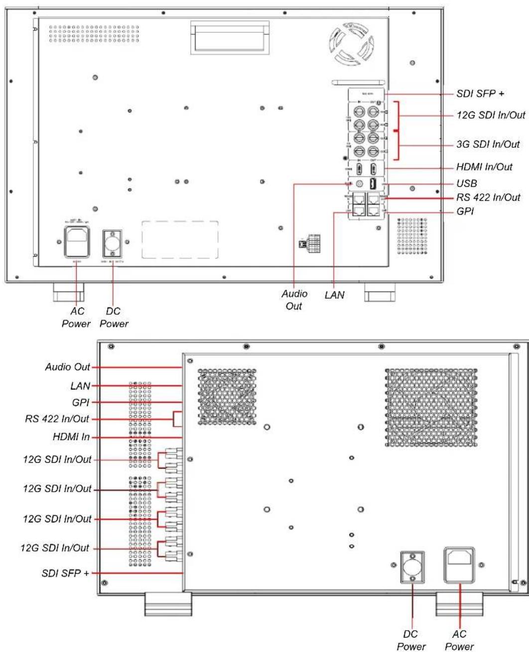
- AC Power: The monitor receives power from the AC inlet, which is a standard IEC receptacle for 100 to 240 VAC ±10%, 50/60 Hz power connection, and includes a Power Switch. Normally the Power switch is kept in the "1" (On) position and the operation of the monitor is controlled from the front panel controls. Four regional AC power cords, supplied according to shipping region, are available.
Important:
By design, the supplied AC mains power cord will only plug into a three-prong grounded outlet for your safety. If the plug does not fit into the outlet, contact an electrician to replace the obsolete outlet.
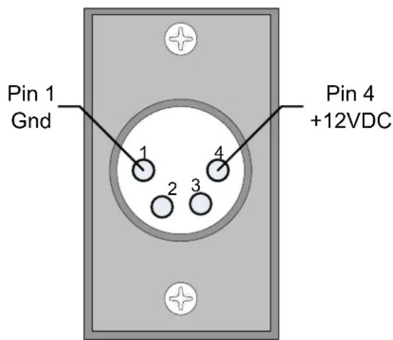
- DC Power: This is a 4-pin XLR-M jack. A 12V battery (not supplied) or a 12VDC power supply (not supplied) can be connected to this connector for operation when not connected to the AC mains. The pinout is shown in Figure 2-3. Observe the polarity shown. This connector may not be present in some models.
Figure 2-3: DC Power Connector Pinout
- Audio Out: This is a 3.5mm stereo jack. It produces analog audio from the monitored video signal. It can be connected to an external audio amplifier or to headphones.
- 12G SDI In/Out: The IN connector receives a 12G/6G/3G/HD/SD-SDI signal to be monitored and the OUT connection outputs this signal. The number of 12G In/Out pairs will vary according to model. Refer to the Tables and Block Diagrams in Chapter 3 of this manual.
- 3G SDI In/Out: The IN connector receives a 3G/HD/SD-SDI signal to be monitored and the OUT connection outputs this signal. The number of 3G In/Out pairs will vary according to model. Refer to the Tables and Block Diagrams in Chapter 3 of this manual.
- HDMI In/Out: An HDMI input and output is provided. They will support a 4096x2160 60Hz (4K/60p) maximum signal.
- RS-422 In/Out: RS-422 In and Out connections are provided. This uses an adaptive TSL3.1 or TSL4.0 protocol. This protocol supports a dynamic UMD/Tally control. The RS-422 interface operates at 38400 baud, 8-bit data, 1 stop bit and even parity. Refer to the pinout in Figure 2-4 and to the connection chart in Table 2-1.
Figure 2-4: RS-422 Jack Pinout
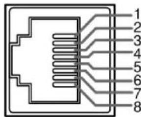
Table 2-1: RS-422 Jack Connections
| Pin | Function |
| 1 GND (Power Ground) | |
| 2 GND (Power Ground) | |
| 3 Tx- | |
| 4 Rx+ | |
| 5 RX- | |
| 6 Tx+ | |
| 7 NC (No Connection) | |
| 8 NC (No Connection) | |
- GPI: A GPI interface is provided for external control. Refer to the pinout in Figure 2-3 and to the connection chart in Table 2-2.
Table 2-2: GPI Jack Connections
| Pin | GPI Signal | Description |
| 1 GPI 1 | Activates when grounded or set to a low level. GPI 1, 2, 3, and 4 functions set in menu. | |
| 2 GPI 2 | ||
| 3 GPI 3 | ||
| 4 NC | No Connection | |
| 5 NC | ||
| 6 GPI 4 As with GPI 1, 2, or 3 above. | ||
| 7 NC No Connection | ||
| 8 GND GPI Ground return | ||
- LAN: This Ethernet port can be used for color correction, upgrading, or remote network control UMD via TSL5.0. Please contact Wohler Technical Service for further information.
10.SDI SFP+: This SFP+ cage accepts an optional 12G/6G/3G/HD/SD-SDI optical input module.
- USB: This USB 2.0 Type A connector allows you to use a flash drive (not supplied) to perform updates to the monitor FPGA, OSD, APP EDP software, or LUT file.
Front Panel Control Operations
The location of the front panel knobs and buttons is shown in Figure 2-5.
Figure 2-5: Front Panel Controls

flowchart
graph LR
    A["POWER"] --> B["Power"]
    C["S1"] --> D["Source Select"]
    E["S2"] --> D
    F["S3"] --> D
    G["S4"] --> H["Function Keys"]
    I["F1"] --> J["Menu"]
    K["F2"] --> L["Volume"]
    M["F3"] --> N["Image"]
    O["F4"] --> P["Menu"]
    Q["F5"] --> R["Menu"]
    S["MENUEXIT"] --> T["VOLUME"]
    U["L+R"] --> V["IMAGE/ADJ"]
-
Power: The Power button is used to turn the monitor on or off. When the monitor is connected to power, but the monitor is off, the indicator will light red. To turn on the monitor, press the Power button and the indicator will light blue. To turn off the monitor, press the Power button for 2 seconds. The delay exists to prevent accidentally turning off the monitor while in use. When the monitor is off, the indicator will light red.
-
Source Select: Each Source Select button will enable a preselected Configuration of an input source and screen parameters needed to support that source, such as color gamut, EOTF, or others. This simplifies changing from source to source. The S1, S2, S3, or S4 buttons will light in blue when each is pressed. Each of these four Source Select buttons can be assigned one of five Configurations, each of which contains eight different monitor settings. Refer to Figure 2-6. Refer to the Function Menu section in the Menus and Options section of this chapter to assign a Configuration to each Source Select button.
Figure 2-6: Source Select Buttons

flowchart
graph LR
    A["Source Select Buttons"] --> B["S1"]
    A --> C["S2"]
    A --> D["S3"]
    A --> E["S4"]
    B --> F["Config 1"]
    C --> G["Config 2"]
    D --> H["Config 3"]
    E --> I["Config 4"]
    E --> J["Config 5"]
    F --> K["Input Source"]
    G --> L["Image Division"]
    H --> M["Audio Source"]
    I --> N["Data Levels"]
    J --> O["Color Space"]
    K --> P["EOTF"]
    L --> Q["Color Temp"]
    M --> R["Waveform Mode"]
-
Function Keys: These five programmable buttons may be set up to quickly turn a variety of display features and functions on or off. Refer to the Function descriptions in the Menu and Options section of this chapter.
-
Menu/Exit: This button allows you to enter or exit the monitor set up menus or return to a previous menu. All of the functions and features of the monitor can be adjusted within the menu structure. Refer to the Menu and Options section of this chapter.
-
Volume: Rotate the Volume knob to adjust the level of the audio being heard in the speakers or in the headphone. While the menus are activated after pressing the Menu/Exit button, rotate this knob to move the menu item selection left or right and then press this knob to select the item. When not in the menu, holding this knob pressed will allow you to select the following adjustments:
a. Volume: Select items related to volume adjustment.
b. Backlight: Select among screen backlight adjustments.
c. Quad Win Select: Rotating the knob will select which Quad View window to select. At this time you may press and turn the Image/Adj knob to adjust the brightness, contrast, and saturation of the selected window.
- Image/Adj: While the menus are activated after pressing the Menu/Exit button, rotate this knob to move the menu item selection up or down. When not in the menu, holding this knob pressed will allow you to select the following adjustments:
a. Brightness: Select items related to screen backlight brightness adjustments.
b. Contrast: Select among image contrast adjustments.
c. Saturation: Select among saturation adjustments. When each adjustment appears, turn the Image/Adj knob to add or subtract the value by 1 or turn the Volume knob to add or subtract the value by 10.
Menus and Options
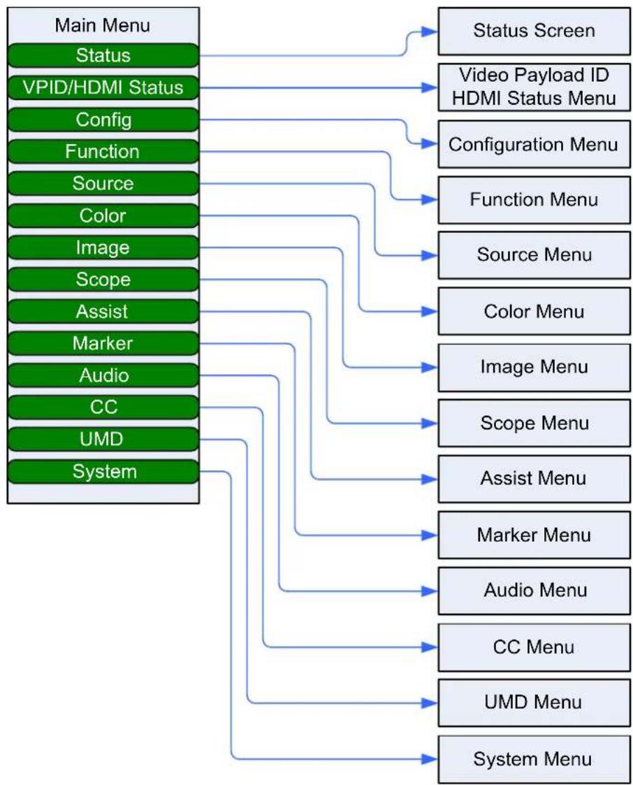
You may set most options or view a variety of system information using the self-contained menus. Figure 2-7 is a diagram of the menu arrangement, a tree showing how to reach any menu from the Main Menu. Hold the Source knob pressed for two seconds to access the Main Menu. Figure 2-8 shows the Main Menu.
Figure 2-7: Menu Tree
flowchart
graph TD
    A["Main Menu"] --> B["Status Screen"]
    A --> C["Video Payload ID HDMI Status Menu"]
    A --> D["Configuration Menu"]
    A --> E["Function"]
    A --> F["Source"]
    A --> G["Color"]
    A --> H["Image"]
    A --> I["Scope"]
    A --> J["Assist"]
    A --> K["Marker"]
    A --> L["Audio"]
    A --> M["CC"]
    A --> N["UMD"]
    A --> O["System"]
    P["Status Screen"] --> Q["Video Payload ID HDMI Status Menu"]
    P --> R["Configuration Menu"]
    P --> S["Function Menu"]
    P --> T["Source Menu"]
    P --> U["Color Menu"]
    P --> V["Image Menu"]
    P --> W["Scope Menu"]
    P --> X["Assist Menu"]
    P --> Y["Marker Menu"]
    P --> Z["Audio Menu"]
    P --> AA["CC Menu"]
    P --> AB["UMD Menu"]
    P --> AC["System Menu"]
Menu Navigation
Press the Menu/Exit button to access the Main Menu. Press it again to exit the menu system when you are finished. Rotate or press the U+D Image and the L+R Volume knobs to make your way through the submenus and make the changes you need to make.
After the initial press of the Menu/Exit button, use the following steps to navigate through the main menu and submenus:
- Rotate the U+D Image knob to highlight the submenu of your choice. Press the U+D Image knob to enter the submenu.
- Within the submenu, rotate the U+D Image knob to travel up or down in the submenu to find the item you would like to change. Then rotate the L+R Volume knob to scroll through the list of available settings for that item. When you reach the setting you want, press the L+R Volume knob. Repeat this process to make all of the changes you would like to make in that submenu.
- When you have finished making changes to the submenu, press the U+D Image knob to exit it. At this point, you may again rotate the U+D Image knob to travel up or down the list of submenus, as in Step 2.
- When you are finished with the menu system, press the Menu/Exit button to exit.
Main Menu
Press the Menu/Exit button to access the Main Menu. Press it again to exit the menu system when you are finished. The Main Menu is shown in Figure 2-8.
Figure 2-8: Main Menu / Status
| Status | Input Mode | Single Input |
| VPID/HDMI Status | Input Format | SDI1 |
| Config | Color Space | Rec 709 |
| Function | Gamma | 2.4 |
| Source | Color Temp | 6500K |
| Color | Backlight | 9 |
| Image | Gateway | 192.168.001.001 |
| Scope | Subnet Mask | 255.255.255.000 |
| Assist | IP Address | 192.168.001.155 |
| Marker | Device ID | 002100415130500F20303 |
| Audio | DSP Version | V74230529 |
| CC | EDP Version | V75230529 |
| UMD | MCU Version | V230608-V440_01_UEF-B |
| System | ||
Status Menu
The first sub menu, Status is initially shown. It shows the status of various items. This menu is view-only and is not meant to be changed. The Status is shown in Figure 2-8. The items it contains are as follows:
- Input Mode: This shows the current input mode of the monitor.
- Input Format: This shows the input format of the signal currently being monitored.
- Color Space: This shows the SMPTE color space of the signal being monitored.
- Gamma: This shows the Gamma value of the signal being monitored.
- Color Temp: This shows the color temperature of the signal being monitored.
- Backlight: This displays the current backlight brightness setting of the screen.
- Gateway: This displays the current Gateway for this monitor. The default value is shown in Figure 2-8.
- Subnet Mask: This displays the current Subnet Mask for this monitor. The default value is shown in Figure 2-8.
- IP Address: This displays the current IP Address for this monitor. The default value is shown in Figure 2-8.
- Device ID: This shows the Device ID for this monitor.
- DSP Version: The internal DSP software version information is shown.
- EDP Version: The internal EDP software version information is shown.
- MCU Version: The internal MCU software version information is shown.
Video Payload ID/HDMI Status Menu
Rotate the U+D Image knob to highlight the VPID/HDMI Status selection and press the U+D Image knob to enter the submenu. This menu will either display the Video Payload ID/HDMI status for the selected HDMI or SDI source. This menu is shown in Figure 2-9.
Use the L+R Volume and U+D Image knobs to travel through the menu and make changes, as explained in the Menu Navigation section of this chapter.
Figure 2-9: VPID/HDMI Status Menu
SDI Source
| Status Channel Select | Channel 1 | |
| VPID/HDMI Status | Source SDI1 | |
| Config | Payload ID 00 00 00 00 | |
| Function | SMPTE Standard Unknown | |
| Source | Color Depth -- | |
| Color | Color Format -- | |
| Image | Picture Rate -- | |
| Scope | Scanning Method -- | |
| Assist | Colorimetry -- | |
| Marker | Link Assignment -- | |
| Audio | ||
| CC | ||
| UMD | ||
| System | ||
HDMI Source
| Status Channel Select | Channel 1 | |
| VPID/HDMI Status | Source HDMI | |
| Config | Color Format -- | |
| Data Level 00 00 00 00 Function | ||
| Source | Color Depth -- | |
| Color | Colorimetry -- | |
| Image | ||
| Scope | ||
| Assist | ||
| Marker | ||
| Audio | ||
| CC | ||
| UMD | ||
| System | ||
The items these menus contain are as follows:
- Channel Select: Use this to select the channel on which to view the various signal parameters.
- Source: Display of the current input signal.
-
Payload ID: Display of the Payload ID. (SDI only)
-
SMPTE Standard: Display of the SMPTE protocol. (SDI only)
-
Color Depth: Display of the Color Depth of the signal.
-
Color Format: Display of the Color Format of the signal.
-
Data Level: Display of the Data Level of the signal. (HDMI only)
-
Picture Rate: Display of the Picture Rate of the signal. (SDI only)
-
Scanning Method: Display of the Scanning Method of the signal. (SDI only)
-
Colorimetry: Display of the Colorimetry of the signal.
-
Link Assignment: Display of the Link Assignment of the SDI signal.
Configuration Menu
Rotate the U+D Image knob to highlight the Config selection and press the U+D Image knob to enter the submenu. This menu will let you save, load or perform other operations on the monitor configurations. This menu is shown in Figure 2-10.
Use the L+R Volume and U+D Image knobs to travel through the menu and make changes, as explained in the Menu Navigation section of this chapter.
Figure 2-10: Config Menu
| Status | Load Config | >> |
| VPID/HDMI Status | Save Config | >> |
| Config | Export Config | >> |
| Function | Import Config | >> |
| Source | Power On Config | Last Config |
| Color | Config1 Name | Config1 |
| Image | Config2 Name | Config2 |
| Scope | Config3 Name | Config3 |
| Assist | Config4 Name | Config4 |
| Marker | Config5 Name | Config5 |
| Audio | Factory Reset | >> |
| CC | ||
| UMD | ||
| System | ||
The items this menu contains are as follows:
- Load Config: Use this to select Configurations 1 through 5 to load.
- Save Config: Use this to select Configurations 1 through 5 to save. Note that in the Function menu, the S1 through S4 buttons, for example, can be set to enable Configurations. After modifying parameters, be sure to save the Configuration by pressing the L+R Volume knob, otherwise pressing the S1 through S4 buttons will still load the previous Configuration.
- Export Config: Use the U disk to export either the current Configuration or all Configurations.
- Import Config: Import either the current Configuration or all Configurations from the U disk.
- Power On Config: This sets which Configuration will be loaded when the
monitor is power up. Either the Configuration will be unchanged from when power was turned off or a Configuration from 1 to 5 may be used.
-
Config1 Name: Use this selection to rename Config 1 with a name that perhaps relates to the input source selected in this Configuration.
-
Config2 Name: Use this selection to rename Config 2.
-
Config3 Name: Use this selection to rename Config 3.
-
Config4 Name: Use this selection to rename Config 4.
-
Config5 Name: Use this selection to rename Config 5.
-
Factory Reset: Using this selection you may reset either the Current Configuration or All Configurations. Use this selection with care since it cannot be undone and will likely require you to set up the monitor from scratch.
Function Menu
Rotate the U+D Image knob to highlight the Function selection and press the U+D Image knob to enter the submenu. This menu will let you set up front panel keys to quickly perform frequently used functions. This menu is shown in Figure 2-11.
Use the L+R Volume and U+D Image knobs to travel through the menu and make changes, as explained in the Menu Navigation section of this chapter.
Figure 2-11: Function Menu
| Status | S1 | Config1 |
| VPID/HDMI Status | S2 | Config 2 |
| Config | S3 | Config3 |
| Function | S4 | Config4 |
| Source | S Key Info | Off |
| Color | Function Preset | Preset 1 |
| Image | F1 | CC Mode |
| Scope | F2 | Data Level |
| Assist | F3 | Color Space |
| Marker | F4 | EOTF |
| Audio | F5 | Color Temp |
| CC | GPI 1 | Marker Display |
| UMD | GPI 2 | Red Tally |
| System | GPI 3 | Green Tally |
| GPI4 | Yellow Tally | |
| Color Quick Select | Quick Rec709 | |
| Data Level Preset | Limit(64-940) | |
| Color Space Preset | Rec709 | |
| EOTF Preset | 2.4 | |
| Function Reset | >> | |
The items this menu contains are as follows:
- S1: Use this to select which Configuration (1 - 5) will load when the S1 panel
key is pressed.
-
S2: Use this to select which Configuration (1 - 5) will load when the S2 panel key is pressed.
-
S3: Use this to select which Configuration (1 - 5) will load when the S3 panel key is pressed.
-
S4: Use this to select which Configuration (1 - 5) will load when the S4 panel key is pressed.
-
S Key Info: Use this to select OFF which will not display S Key information or to select ON, which will cause S Key information to be displayed.
-
Function Preset: Presets 1 to 4 can be selected.
-
F1: Any one of a large variety of functions can be assigned to the F1 key.
-
F2: Any one of a large variety of functions can be assigned to the F2 key.
-
F3: Any one of a large variety of functions can be assigned to the F3 key.
-
F4: Any one of a large variety of functions can be assigned to the F4 key.
-
F5: Any one of a large variety of functions can be assigned to the F5 key.
-
GPI 1: Any one of a large variety of functions can be assigned to the GPI 1 key.
-
GPI 2: Any one of a large variety of functions can be assigned to the GPI 2 key.
-
GPI 3: Any one of a large variety of functions can be assigned to the GPI 3 key.
-
GPI 4: Any one of a large variety of functions can be assigned to the GPI 4 key.
-
Color Quick Select: Preset the Color so that it can be preset in an F function key for quick selection.
-
Data Level Preset: Preset the Data Level so that it can be preset in an F function key for quick selection. Note: To preset the Data Level, the Color Quick Select must first be set to User.
-
Color Space Preset: Preset the Color Space so that it can be preset in an F function key for quick selection. Note: To preset the Color Space, the Color Quick Select must first be set to User.
-
EOTF Preset: Preset the EOTF so that it can be preset in an F function key for quick selection. Note: To preset the EOTF, the Color Quick Select must first be set to User.
-
Function Reset: Reset all of the settings in this menu to the Factory Settings.
Source Menu
Rotate the U+D Image knob to highlight the Source selection and press the U+D Image knob to enter the submenu. This menu will let you set up details about the input Sources. This menu is shown in Figure 2-12.
Use the L+R Volume and U+D Image knobs to travel through the menu and make changes, as explained in the Menu Navigation section of this chapter.
Figure 2-12: Source Menu
| Status | Display Mode | Single |
| VPID/HDMI Status | Input Mode | Single Input |
| Config | Win1 Source | SDI1 |
| Function | Win2 Source | SDI2 |
| Source | Win3 Source | SDI3 |
| Color | Win4 Source | HDMI |
| Image | SDI1 Rename | SDI1 |
| Scope | SDI2 Rename | SDI2 |
| Assist | SDI3 Rename | SDI3 |
| Marker | SDI4 Rename | SDI4 |
| Audio | SFP Rename | SFP |
| CC | HDMI Rename | HDMI |
| UMD | Win Border | OFF |
| System | Win1 Border Color | Green |
| Win1 Border Color | Green | |
| Win1 Border Color | Green | |
| Win1 Border Color | Green | |
| Win1 Border Width | 6PX | |
| Win1 Border Width | 6PX | |
| Win1 Border Width | 6PX | |
| Win1 Border Width | 6PX |
The items this menu contains are as follows:
-
Display Mode: Use this to select either Single or Quad display mode. The arrangement of the windows on the screen is shown at right.
-
Input Mode: Use this to select the signal input mode as follows:
a. Single: The selected source is displayed full screen.
b. Quad: The four selected sources are displayed on four sub screens.
c. SDI Dual Link: Selects Dual Link input mode.
d. SDI 2SI: Selects 2SI input mode.
e. SDI SQD: Selects SQD input mode.
| Win 1 Win 2 | |
| Win 3 Win 4 |
-
Win1 Source: This selects which input will display on Window 1. The choices are SDI1, SDI2, SDI3, SDI4, SFP, and HDMI.
-
Win2 Source: This selects which input will display on Window 2, if it is enabled. The choices are SDI1, SDI2, SDI3, SDI4, SFP, and HDMI.
- Win3 Source: This selects which input will display on Window 3, if it is enabled. The choices are SDI1, SDI2, SDI3, SDI4, SFP, and HDMI.
- Win4 Source: This selects which input will display on Window 4, if it is enabled. The choices are SDI1, SDI2, SDI3, SDI4, SFP, and HDMI.
- SDI1 Rename: This allows you to provide SDI 1 with a custom name.
- SDI2 Rename: This allows you to provide SDI 2 with a custom name.
- SDI3 Rename: This allows you to provide SDI 3 with a custom name.
- SDI4 Rename: This allows you to provide SDI 4 with a custom name.
- SFP Rename: This allows you to provide the SFP input with a custom name.
- HDMI Rename: This allows you to provide the HDMI input with a custom name.
- Output Signal: This selects which input will appear on the HDMI output. The choices are SDI1, SDI2, SDI3, SDI4, SFP, HDMI input (if one exists), or whichever input is appearing on Window 1 of the monitor.
The following selections are available only if Quad input mode is selected:
-
Win Border: This turns the wire frame window border(s) ON or OFF.
-
Win1 Border Color: A choice of colors is available for the Win1 screen: White, Green, Blue, Cyan, Red, or Yellow.
-
Win2 Border Color: A choice of colors is available for the Win2 screen: White, Green, Blue, Cyan, Red, or Yellow.
-
Win3 Border Color: A choice of colors is available for the Win3 screen: White, Green, Blue, Cyan, Red, or Yellow.
-
Win4 Border Color: A choice of colors is available for the Win4 screen: White, Green, Blue, Cyan, Red, or Yellow.
-
Win1 Border Width: The width of the wire frame for the Win1 screen can be selected in pixels: 3PX, 6PX, or 8PX.
-
Win2 Border Width: The width of the wire frame for the Win2 screen can be selected in pixels: 3PX, 6PX, or 8PX.
-
Win3 Border Width: The width of the wire frame for the Win3 screen can be selected in pixels: 3PX, 6PX, or 8PX.
-
Win4 Border Width: The width of the wire frame for the Win4 screen can be selected in pixels: 3PX, 6PX, or 8PX.
Color Menu
Rotate the U+D Image knob to highlight the Color selection and press the U+D Image knob to enter the submenu. This menu will let you set up details about the color display characteristics. This menu is shown in Figure 2-13.
Use the L+R Volume and U+D Image knobs to travel through the menu and make changes, as explained in the Menu Navigation section of this chapter.
Figure 2-13: Color Menu
| Status | Color Ctrl | All Screen |
| VPID/HDMI Status | Channel Select | Win1 |
| Config | Cross Partition Show | Auto |
| Function | Data Level | Auto |
| Source | Color Space | Rec709 |
| Color | EOTF | 2.4 |
| Image | Transfer Matrix | Auto |
| Scope | R Saturation | 50 |
| Assist | G Saturation | 50 |
| Marker | B Saturation | 50 |
| Audio | R Hue | 0 |
| CC | G Hue | 0 |
| UMD | B Hue | 0 |
| System | Sharpness | 10 |
| DBrightness | 0 | |
| Contrast | 0 | |
| Color Temp | 6500K | |
| R Gain | 512 | |
| G Gain | 512 | |
| B Gain | 512 | |
| R Offset | 512 | |
| G Offset | 512 | |
| B Offset | 512 |
The items this menu contains are as follows:
- Color Control: This setting will select how the color settings are applied:
a. Full Screen: The color settings will apply to the whole screen.
b. Zone Ctrl: Different color settings can be set for each window. This setting is only available in Quad mode.
-
Channel Select: The Win1, Win2, Win3, and Win4 settings cause the color settings in this menu to apply to the individual window. The arrangement of the windows on the screen is shown at right.
-
Cross Partition Show: This is a Reserved function that is not yet implemented. The settings are Auto or ON.
-
Data Level: A choice of Data Levels is offered:
| Win 1 Win 2 | |
| Win 3 Win 4 |
a. Auto: The Data Level of the input signal is set automatically.
b. Limited: 64-940
c. Extended: 64-1023
d. Full: 0-1023
e. SMPTE Full: 4-1019
- Color Space: A choice of Color Space is offered:
a. Auto: The Color Space of the input signal is matched automatically.
b. Bypass: The Color Table selection is bypassed.
c. Rec709: The Color Table selected is REC709.
d. EBU: The Color Table selected is EBU.
e. DCI P3 D65: The Color Table selected is DPI P3 D65.
f. DCI P3: The Color Table selected is DCI P3.
g. Rec2020: The Color Table selected is Rec2020.
h. U1_User1, U2_User2, U3_User3, U4_User4, U5_User5, U6_User6: Up to 6 color table can be loaded into the monitor. U1_User1 through U6_User6 allow you to select between them.
-
EOTF: A choice of EOTF is offered to allow for a selection according to the requirements: Bypass (Bypass uses the Gamma of the monitor screen.), Gamma 2.0, 2.2, 2.4, 2.6, 2.4(HDR), Rec.2100 HLG 1.03, 1.11, 1.16, 1.20, 1.27, 1.33, ST2084 PQ, ST2084 PQ (softroll), Slog, Slog2, Slog3, Clog, Clog2, Clog3, Vlog, Dlog, or LogC.
-
Transfer Matrix: The available choices are: Auto (Automatically select a transfer matrix that matches the input signal.), Rec 601, Rec 709, or Rec 2020.
-
R Saturation: The range of Red Saturation values is 0 to 200. The default value is 50.
-
G Saturation: The range of Green Saturation values is 0 to 200. The default value is 50.
-
B Saturation: The range of Blue Saturation values is 0 to 200. The default value is 50.
-
R Hue: The range of Red Hue values is -100 to 100. The default value is 0.
-
G Hue: The range of Green Hue values is -100 to 100. The default value is 0.
-
B Hue: The range of Blue Hue values is -100 to 100. The default value is 0.
-
Sharpness: The adjustable range of Sharpness is 0 to 20. The default value is 10.
-
DBrightness: The adjustable range of Display Brightness is -2000 to 2000. The default value is 0.
-
Contrast: The adjustable range of Display Contrast is -2000 to 2000. The default value is 0.
-
Color Temp: The available Color Temperature settings are 6500K, 9300K,
5500K, or User 1 to User 6. You may customize the Color Temperature, save it to a corresponding User Mode (User1 through User6) in a configuration, assign that configuration to a S1 to S4 Select key, and then use that S1 to S4 key to load it. Note: After modifying the parameters, be sure to go to the Config menu and save the Configuration. Otherwise, the S1 to S4 keys will continue to load the previous Configuration.
- R Gain: The adjustable range of Red Gain is 0 to 1023. This can only be adjusted in Color Temperature User mode.
- G Gain: The adjustable range of Green Gain is 0 to 1023. This can only be adjusted in Color Temperature User mode.
- B Gain: The adjustable range of Blue Gain is 0 to 1023. This can only be adjusted in Color Temperature User mode.
- R Offset: The adjustable range of Red Gain is 0 to 1023. This can only be adjusted in Color Temperature User mode.
- G Offset: The adjustable range of Green Gain is 0 to 1023. This can only be adjusted in Color Temperature User mode.
- B Offset: The adjustable range of Blue Gain is 0 to 1023. This can only be adjusted in Color Temperature User mode.
Image Menu
Rotate the U+D Image knob to highlight the Image selection and press the U+D Image knob to enter the submenu. This menu will let you set up details about how the image will be displayed. This menu is shown in Figure 2-14.
Use the L+R Volume and U+D Image knobs to travel through the menu and make changes, as explained in the Menu Navigation section of this chapter.
Figure 2-14: Image Menu
The items this menu contains are as follows:
- Backlight: The range of Backlight adjustment is 0 to 100.
- Aspect Ratio: The available settings are Full Screen, Original Screen and
1:1.
-
Freeze: The ON or OFF setting will control whether to freeze the screen.
-
Over Scan: The ON or OFF setting will control whether Over Scan is enabled or not.
-
Mirror/Rotation: The settings are as follows:
a. OFF: The orientation of the image on the screen is normal.
b. Mirror: The screen image is mirrored horizontally.
c. Rotation: The screen image is rotated 180irc and appears upside-down.
- Blue Mode/Mono: The settings are as follows:
a. OFF: The Blue Mode feature is turned off.
b. Mono: A black and white monochrome image is displayed.
c. Blue: Full Blue Mode is enabled.
d. Red: Full Red Mode is enabled.
e. Green: Full Green Mode is enabled.
Scope Menu
Rotate the U+D Image knob to highlight the Scope selection and press the U+D Image knob to enter the submenu. This menu allows you to define Waveform, Vector, and Histogram appearance on the screen. This menu is shown in Figure 2-15.
Use the L+R Volume and U+D Image knobs to travel through the menu and make changes, as explained in the Menu Navigation section of this chapter.
Figure 2-15: Scope Menu
| Status | Waveform | Off |
| VPID/HDMI Status | Waveform Scale | Digital |
| Config | Waveform Alarm | 80 |
| Function | Waveform Filter | Off |
| Source | Vector | Off |
| Color | Histogram | Off |
| Image | Measure Channel | Win1 |
| Scope | ||
| Assist | ||
| Marker | ||
| Audio | ||
| CC | ||
| UMD | ||
| System |
The items it contains are as follows:
- Waveform: There are the following Waveform Functions:
a. OFF: The Waveform measurement is off and will not display.
b. LUMA: The LUMA waveform will display.
c. YCbCr: The YcbCr waveform will display.
d. RGB: The RGB waveform will display.
e. Quad Luma: This will display Quad Luma. This function is only available in Quad Mode.
- Waveform Scale: The Waveform Scale may be set to:
a. Digital: The Waveform Scale is displayed numerically.
b. IRE: The Waveform Scale is displayed as a percentage of luminance.
c. Luma PG: The HDR PQ luminance waveform is displayed.
d. Luma HLG: The Luma HLG luminance waveform is displayed.
- Waveform Alarm: The Waveform Alarm display can be set to any percentage with the range of 80% to 100%. When the measured waveform reaches or exceeds this percentage, an alarm will occur and the alarm will be indicated in red.
- Waveform Filter: Display of the Waveform Filter may be turned ON or OFF.
- Vector: This controls the Vector display as follows:
a. OFF: No Vector display
b. 100: The vector illustration is 100% of the display.
c. 75: The vector illustration is 75% of the display.
- Histogram: This controls the Histogram display as follows:
a. OFF: Turn off the Histogram display.
b. LUMA: Display the brightness histogram.
c. RGB: Display theRGB histogram.
- Channel Select: This adjustment is only available when the monitor is in Quad View mode. It controls which channel will be the subject of the Waveform display. The choices are Channel 1, Channel 2, Channel 3, or Channel 4.
Assist Menu
Rotate the U+D Image knob to highlight the Assist selection and press the U+D Image knob to enter the submenu. This menu allows you to enable or disable the various Assist functions of the monitor. This menu is shown in Figure 2-16.
Use the L+R Volume and U+D Image knobs to travel through the menu and make changes, as explained in the Menu Navigation section of this chapter.
Figure 2-16: Assist Menu
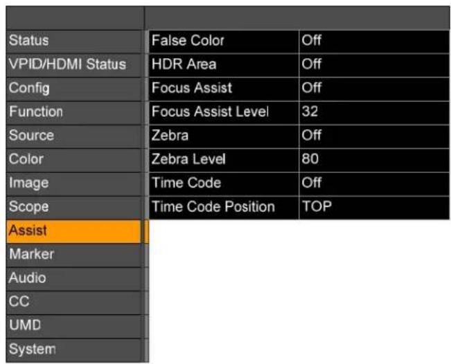
The items it contains are as follows:
- False Color: False Color may be turned ON, OFF, or turned ON with HDR.
- HDR Area: The HDR Area function shows the HDR percentage of the input signal. It may be turned ON or OFF.
- Focus Assist: Focus Assist may be displayed as follows:
a. OFF: No Focus Assist
b. Red: Show Focus Assist in Red.
c. Green: Show Focus Assist in Green.
d. Blue: Show Focus Assist in Blue.
- Focus Assist Level: When Focus Assist is on, Focus Gain can be set to any level between 0 and 100.
- Zebra: the Zebra display may be set to ON or OFF.
- Zebra Level: The Zebra Level may be set to any value between 0% and 100%. When the brightness in the monitored image reaches or exceeds the set percentage, an alarm will occur and the parts of the monitored image that exceed will be overlaid with a red zebra pattern.
- Time Code: The existence or characteristics of the Time Code display may be set as follows:
a. OFF: Time Code will not be displayed.
b. VITC1: The Time Code will be displayed as VITC1.
c. VITC2: The Time Code will be displayed as VITC2.
d. LTC: The Time Code will be displayed as LTC.
Note: Time Code cannot be displayed on HDMI signals.
- Time Code Position: The Time Code display may be set to the Top of the screen or the Bottom of the screen.
Marker Menu
Rotate the U+D Image knob to highlight the Marker selection and press the U+D Image knob to enter the submenu. This menu allows you to set the various Marker functions of the monitor. This menu is shown in Figure 2-17.
Use the L+R Volume and U+D Image knobs to travel through the menu and make changes, as explained in the Menu Navigation section of this chapter.
Figure 2-17: Marker Menu
| Status | Marker Display | Off |
| VPID/HDMI Status | Aspect Marker | 1.85:1 |
| Config | Center Marker | On |
| Function | Safety Area | 80 |
| Source | Fit Marker | Off |
| Color | Marker Mat | Off |
| Image | Marker Line Color | Green |
| Scope | Box Display | Off |
| Assist | Box Center | On |
| Marker | Box Mat | Off |
| Audio | Box Line Color | Green |
| CC | Box Line Width | 4PX |
| UMD | Box HStart | 100 |
| System | Box VStart | 100 |
| Box Width | 3640 | |
| Box Height | 1960 |
The items it contains are as follows:
-
Marker Control: This selection turns all markers ON you have enabled or turns them OFF.
-
Aspect Marker: The Area Marker may be set to OFF or may be set to various ratios: 4:3, 16:9, 15:9, 14:9, 13:9, 1.85:1, or 2.35:1.
-
Center Marker: The Center Marker may be turned to OFF or ON.
-
Safety Area: The Safety Area marking may be turned OFF or it may be set to various percentages: 80%, 85%, 88%, 90%, or 93%.
-
Fit Marker: The Fit Marker may be turned OFF or ON.
-
Marker Mat: The Marker Mat may be turned OFF or it may be set to Black or Gray.
-
Marker Line Color: This turns the Marker Line on and to one of the following colors: White, Red, Green, Blue, or Gray.
-
Box Display: The Box Display may be turned OFF or ON.
- Box Center: The Box Center may be turned OFF or ON.
- Box Mat: This is the color of the filling outside of the Box wire frame. It may be set to OFF, White, Black, Translucent, Red, Green, or Blue.
- Box Line Color: The color of the Box wire frame may be set to: White, Green, Blue, Cyan, Red, or Yellow.
- Box Line Width: The thickness in pixels of the Box wire frame line may be set to 4PX or 8PX.
- Box HStart: The horizontal start position of the Box wire frame may be set anywhere between 0 and 3840.
- Box VStart: The vertical start position of the Box wire frame may be set anywhere between 0 and 2160.
- Box Width: The horizontal width of the Box wire frame may be set anywhere between 0 and 3840.
- Box Height: The vertical height of the Box wire frame may be set anywhere between 0 and 2160.
Audio Menu
Rotate the U+D Image knob to highlight the Audio selection and press the U+D Image knob to enter the submenu. This menu allows you to set the various Audio setups and displays on the monitor. This menu is shown in Figure 2-18.
Use the L+R Volume and U+D Image knobs to travel through the menu and make changes, as explained in the Menu Navigation section of this chapter.
Figure 2-18: Audio Menu
| Status | Audio Source | Win1 |
| VPID/HDMI Status | Left Audio Channel | Ch1 |
| Config | Right Audio Channel | Ch2 |
| Function | Audio Mode | Normal |
| Source | Volume | 15 |
| Color | Mute | Off |
| Image | Audio Phase | Off |
| Scope | Audio Level Meter | Off |
| Assist | Meter Display Mode | Vertical |
| Marker | Meter Select | CH1-2 |
| Audio | ||
| CC | ||
| UMD | ||
| System |
The items it contains are as follows:
- Audio Source: The Audio Source can be set to Win1, Win2, Win3, or Win4. This function is only available in Quad Mode.
- Left Audio Channel: The Audio source of the left channel can be set to any
input channel 1 through 16.
- Right Audio Channel: The audio source of the right channel can be set to any input channel 1 through 16.
- Audio Mode: The Audio Mode can be set to:
a. Normal: Both left and right channels are output.
b. Right Channel Mute: Only the left channel is output.
c. Left Channel Mute: Only the right channel is output.
- Volume: The Volume Adjustment can be set from 0 to 31.
- Mute: The Mute function may be turned OFF to listen to audio or ON to silence audio.
- Audio Phase: Audio Phase measurement may be turned ON or OFF.
- Audio Level Meter: The Audio Level meters may be turned ON or OFF.
- Meter Display Mode: When the Audio Level Meters are turned on, the Meter Display Mode allows them to be displayed either vertically or horizontally.
- Meter Select: When the Audio Level Meters are turned on, they may display audio from the following choice of channels: 1&2, 3&4, 5&6, 7&8, 9&10, 11&12, 13&14, 15&16.
CC Menu
Rotate the U+D Image knob to highlight the CC Settings selection and press the U+D Image knob to enter the submenu. This menu allows you to set the various Closed Caption setups and displays on the monitor. This menu is shown in Figure 2-19.
Use the L+R Volume and U+D Image knobs to travel through the menu and make changes, as explained in the Menu Navigation section of this chapter.
Figure 2-19: CC Menu
| Status | Channel Select Channel 1 | |
| VPID/HDMI Status | CC Mode OFF | |
| Config | CC 608 CC 1 | |
| Function | CC 708 Service 1 | |
| Source | ||
| Color | ||
| Image | ||
| Scope | ||
| Assist | ||
| Marker | ||
| Audio | ||
| CC | ||
| UMD | ||
| System | ||
The items it contains are as follows:
- Channel Source: The Source of the Closed Captions can be set to SDI1, SDI2, SDI3, or SDI4.
-
CC Mode: The three CC Mode settings are:
a. OFF: Closed Captions will not be displayed.
b. 708: 708 Closed Captions will be displayed.
c. 608: 608 Closed Captions will be displayed. -
CC 608: Type CC 1, CC 2, CC 3, or CC 4 Mode 608 Closed Captions may be selected.
-
CC 708: Service Type 1, 2, 3, 4, 5, 6, or 7 Mode 708 Closed Captions may be selected.
UMD Menu
Rotate the U+D Image knob to highlight the UMD selection and press the U+D Image knob to enter the submenu. This menu allows you to set the various UMD setups and displays on the monitor. This menu is shown in Figure 2-20.
Use the L+R Volume and U+D Image knobs to travel through the menu and make changes, as explained in the Menu Navigation section of this chapter.
Figure 2-20: UMD Menu
| Status | UMD Display Off | |
| VPID/HDMI Status | UMD Color White | |
| Config | UMD Protocol TSL 3.1 | |
| Function | UMD Character 1 Channel1 | |
| Source | UMD Character 2 Channel2 | |
| Color | UMD Character 3 Channel3 | |
| Image | UMD Character 4 Channel4 | |
| Scope | UMD ID 0 | |
| Assist | UMD Screen ID 0 | |
| Marker | UMD Display ID 0 | |
| Audio | Baud Rate 38400 | |
| CC | LED Tally Off | |
| UMD | UMD Tally Color RG | |
| System | Tally Source TSL | |
| Port Number 3000 | ||
The items it contains are as follows:
- UMD Display: The UMD Display may be turned ON or OFF.
- UMD Color: The color of the UMD Display my be set to Green, Red, White, or Black.
- UMD Protocol: The UMD Protocol can be set to:
a. Local: The UMD characters can be set locally.
b. TSL3.1: The UMD characters can be set remotely using TSL3.1 protocol using an RS422 interface, 8-bits, 1 stop bit, even parity, 38400 baud.
c. TSL4.0: The UMD characters can be set remotely using TSL4.0 protocol using an RS422 interface, 8-bits, 1 stop bit, even parity, 38400 baud.
d. TSL5.0: The UMD characters can be set remotely using TSL5.0 protocol using the LAN interface, with the default IP address of the monitor: 192.168.1.155.
- UMD Character 1: The name that will appear in single screen mode or in Win1 when in Quad Mode.
- UMD Character 2: The name that will appear in Win2 when in Quad Mode.
- UMD Character 3: The name that will appear in Win3 when in Quad Mode.
- UMD Character 4: The name that will appear in Win4 when in Quad Mode.
- UMD ID: The IMD ID address can be set anywhere from 0 to 126. When multiple monitors are cascaded, each monitor can be set to a different address so that they may be distinguished individually. This address is used by the RS-422 connection when TSL3.1 or TSL4.0 protocol is used.
- UMD Screen ID: The IMD Screen ID can be set anywhere from 0 to 65534. This is only available when using TSL5.0 protocol.
- UMD Display ID: The IMD Display ID can be set anywhere from 0 to 65534. This is only available when using TSL5.0 protocol.
- Baud Rate: The RS-422 baud rate may be set to one of the following values: 4800, 9600, 19200, 38400, 57600, or 115200. The default baud rate is 38400.
- LED Tally: The LED Tally may be turned ON or OFF.
- UMD Tally Color: The UMD Tally Color may be set as follows:
a. OFF: OSD Tally is turned off.
b. RG: This selects OSD Tally RG Mode.
c. GR: This selects OSD Tally GR Mode.
d. RGY: This selects OSD Tally RGY Mode.
- Tally Source: The Tally Source may be set as follows:
a. GPI: GPI protocol is selected.
b. TSL: TSL protocol is selected.
- Port Number: The Network Port Number is 3000.
System Menu
Rotate the U+D Image knob to highlight the System selection and press the U+D Image knob to enter the submenu. This menu allows you to set the various parameters that apply to the monitor as a system. This menu is shown in Figure 2-21.
Use the L+R Volume and U+D Image knobs to travel through the menu and make changes, as explained in the Menu Navigation section of this chapter.
Figure 2-21: System Menu
| Status | Key Lock | Off |
| VPID/HDMI Status | Language | English |
| Config | Menu Display Timer | 30 |
| Function | Menu Position | Right Bottom |
| Source | OSD Blend | 15 |
| Color | DPMS | Always on |
| Image | Key Led | Level 1 |
| Scope | Source Info | Off |
| Assist | USB Mode | USB Flash Disk |
| Marker | USB Upgrade | >> |
| Audio | DHCP | Off |
| CC | Gateway | 192.168.001.001 |
| UMD | Subnet Mask | 255.255.255.000 |
| System | IP Address | 192,168.001.115 |
The items it contains are as follows:
- Key Lock: The Key Lock may be turned ON or OFF.
-
Language: The language used in the menu system of this monitor may be set to either English or Chinese.
-
Menu Display Timer: The Menu Display Timer can be set anywhere from 5 to 60 seconds. When this time lapses, the menu will disappear from the screen.
-
Menu Position: The location of the menu can be set to the top left, top right, bottom left, or bottom right on the screen.
-
DPMS: This setting controls the back light and power saving operation of the monitor;
a. Always ON: The screen backlight will always be on.
b. Light Sleep: The screen backlight will turn off when there is no signal and no operation for 1 minute.
c. Deep Sleep: The monitor will enter ECO mode when there is no signal and no operation for 1 minute. The monitor can be awakened by pressing the Power button.
-
Key LED: The level of the Key indicator can be set as follows: OFF, Level 1, or Level 2.
-
Source Info: Source Info may be turned ON or OFF.
-
USB Mode: The source of monitor upgrades can be set to either USB Flash
Disk or to via a USB connection to a PC.
- USB Upgrade: You may upgrade the various firmware parts of the monitor via USB. The firmware to be upgraded includes FPGA, LUTs, OSD, EDP, APP, or all of the firmware.
- DHCP: Network setting DHCP may be turned ON or OFF.
- Gateway: The network Gateway may be set as follows:
a. 255.255.255.000: Set a custom Gateway.
b. 0: The Default Gateway is set to 192.168.001.001.
- Subnet Mask: The Subnet mask settings are:
a. 255.255.255.000: Set a custom subnet mask.
b. 0: The default Subnet Mask is 255.255.255.000.
- IP Address: The default IP Address is 192.168.1.155.
Commonly Used Setups
The many settings in the menus of this monitor provide great flexibility in setting it up for many different tasks. However, this may be daunting for a new customer. This section provides step by step examples of how to perform some basic setups.
Input Source Selection, Single Picture Mode
Switching to view another source may involve more than simply switching the input source. It may also require the changing of various parameters such as gamut, EOTF, and so on. The vMON monitors make switching inputs simple, but setting up each input first requires a few steps. For example to set SDI 3 as the input source for a full screen display, use the following steps:
- Connect the signal to be monitored to the SDI 3 BNC.
- Press the MENU/EXIT button and then go down to the Source submenu.
- In this menu, set the Display Mode to Single, the Input Mode to Single Input, and the Win1 Source to SDI3.
- Go to the Function submenu and set S1 to Config1.
- Go to the Config submenu, set Save to Config1 and press the Volume Knob to save.
- After saving, from now on pressing the S1 button will cause SDI 3 to display.
Input Source Selection, Quad Split Mode
To set Win1 to display SDI 1, Win2 to display SDI2, Win3 to display SDI3 and Win4 to display HDMI, use the following steps:
- Connect the four signals to be monitored to the appropriate inputs on the monitor.
-
Press the Menu/Exit button and then go down to the Source submenu.
-
Set the Display Mode to Quad, set Input Mode to Quad Input, set the Win1 Source to SDI 1, set the Win2 Source to SDI 2, set the Win3 Source to SDI 3, and set the Win4 source to HDMI.
- Go to the Function submenu and set S2 to Config1.
- Go to the Config submenu, set Save to Config1 and press the Volume Knob to save.
- After saving, from now on pressing the S2 button will cause the Quad Split of the four input signals to display as follows:
| Win1SDI 1 | Win2SDI 2 |
| Win3SDI 3 | Win4HDMI |
Input Source Selection, SDI SQD/2SI
This sections the steps necessary to set up either SDI SQD or SDI 2SI to monitor a 4K signal. These steps are essentially the same for SDI SQD and SDI 2SI. Note that only vMON monitors that are capable of 8K can be set up to display an 8K signal. Use the following steps:
- Connect the signals to be monitored to the SDI 1/2/3/4 BNCs.
- Press the Menu/Exit button and then go down to the Source submenu.
- Set the Display Mode to Single and set Input Mode to SDI SQD.
- Go to the Function submenu and set S3 to Config1.
- Go to the Config submenu, set Save to Config1 and press the Volume Knob to save.
- After saving, from now on pressing the S3 button will display the 4K signal in Quad Lind SDI SQD Mode.
Configuration Settings
The configuration settings described above can also contain many other parameters such as brightness, contrast, EOTF curve, color gamut, and so on, in addition to simply the input source. In the following steps, Config5 will be set to display an HDMI signal, but with changed parameters:
- Connect the HDMI signal to be monitored to the HDMI input.
- Press the Menu/Exit button and then go down to the Source submenu.
- Set the Display Mode to Single, set Input Mode to SDI SQD, and set the Win1 Source to HDMI.
- Go down to the Color submenu and set the Color Space to U1_User1.
-
Go down to the Image submenu and set the Backlight to 80.
-
Go back to the Function submenu and set S2 to Config5.
- Go to the Config submenu, set Save to Config5 and press the Volume Knob to save.
- After saving, from now on pressing the S2 button will display the HDMI signal in Single Picture Mode, with the Color Space as U1_User1 and the Brightness set to 80.
Function Key Settings
Using the Function Preset setting in the Function menu, you may set up four different Function Key Presets. In normal operation, press the F key once and the Function Key Menu, as shown in Figure 2-22, pops up. The action performed by each of the Functions keys may also be set in this menu.
Pressing an S1 - S4 key after the Function Key Menu pops up will allow you to switch to a different Function Key Preset Group.
Figure 2-22: Function Key Menu
| Functions | ||
| Change | Preset: S1-S4 | Preset 1 |
| F1 | CC Mode | Off |
| F2 | Data Level | Auto |
| F3 | Color Space | Rec709 |
| F4 | EOTF | 2.4 |
| F5 | Color Temp | 6500K |
Table 3-1: vMON-170-4K, vMON-170-8K Specifications
| Specification | Values/Domains |
| Power Requirements | 100 VAC to 240 VAC ± 10%, 50/60Hzor 12 VDC |
| Power Consumption 50 Watts | |
| Dimensions (H x W x D) | 17.1" x 12.6" x 5.9" (433mm x 321mm x 150mm) |
| Shipping/Net Weight | 17.2 lbs (7.8 kg) / 11.7 lbs (5.3 kg) |
| Supplied Accessories AC Power Cord | |
| Display Type | 17.3" diagonal;216.8mm (H) x 135.5mm (V) |
| Screen Resolution 3840H x 2160V 4K resolution | |
| Luminance / Contrast 400 cd/m 2 / 1000:1 | |
| Audio Meter Channels 2-16 per display window | |
| Color Depth 16.7 million | |
| Backlight LED | |
| Video Inputs | 16 channels from:4 x BNC 12G-SDI1 x HDMI 2.01 x SDI SFP+ input cage for optical module |
| Video Outputs | 4 x BNC looped 12G-SDI |
| Audio Output | 1 x 3.5mm stereo headset jack |
Table 3-2: vMON-240-4K Specifications
| Specification | Values/Domains |
| Power Requirements | 100 VAC to 240 VAC ± 10%, 50/60Hzor 12 VDC |
| Power Consumption 70 Watts | |
| Dimensions (H x W x D) | 22.7" x 15.8" x 5.9" (578mm x 401mm x 150mm) |
| Shipping/Net Weight | 25.2 lbs (11.4 kg) / 20 lbs (9.1 kg) |
| Supplied Accessories AC Power Cord | |
| Display Type | 24" diagonal;525.7mm (H) x 295.7mm (V) |
| Screen Resolution 3840H x 2160V 4K resolution | |
| Luminance / Contrast 400 cd/m 2 / 1000:1 | |
| Audio Meter Channels 2-16 per display window | |
| Color Depth 1.07 billion | |
| Backlight LED | |
| Video Inputs | 16 channels from:• 2 x BNC 12G-SDI• 1 x HDMI 2.0• 1 x SDI SFP+ input cage for optical module |
| Video Outputs | • 2 x BNC looped 12G-SDI• 2 x BNC looped 3G-SDI |
| Audio Output | • 1 x 3.5mm stereo headset jack |
Table 3-3: vMON-270-4K, vMON-270-8K Specifications
| Specification | Values/Domains |
| Power Requirements | 100 VAC to 240 VAC ± 10%, 50/60Hzor 12 VDC |
| Power Consumption 63 Watts | |
| Dimensions (H x W x D) | 26.3" x 17.4" x 6.3" (649mm x 441mm x 160mm) |
| Shipping/Net Weight 30.9 | lbs (14 kg) / 25.8 lbs (11.7 kg) |
| Supplied Accessories AC Power Cord | |
| Display Type | 27" diagonal;609.6mm (H) x 431.8mm (V) |
| Screen Resolution 3840H x 2160V 4K resolution | |
| Luminance / Contrast 400 cd/m 2 / 2000:1 | |
| Audio Meter Channels 2-16 per display window | |
| Color Depth 1.07 billion | |
| Backlight LED | |
| Video Inputs | 16 channels from:2 x BNC 12G/6G/3G/HD/SD-SDI2 x BNC 3G/HD/SD-SDI1 x HDMI 2.01 x SDI SFP+ input cage for optical module |
| Video Outputs | 2 x BNC looped 12G/6G/3G/HD/SD-SDI2 x BNC looped 3G/HD/SD-SDI |
| Audio Output | 1 x 3.5mm stereo headset jack |
Table 3-4: vMON-320-4K, vMON-320-8K Specifications
| Specification | Values/Domains |
| Power Requirements | 100 VAC to 240 VAC ± 10%, 50/60Hzor 12 VDC |
| Power Consumption 50 Watts | |
| Dimensions (H x W x D) | 29.5" x 19.6" x 6.3" (750mm x 498mm x 160mm) |
| Shipping/Net Weight 58.0 lbs (26.3 kg) / 27.7 lbs (12.5 kg) | |
| Supplied Accessories AC Power Cord | |
| Display Type | 32.5" diagonal;274.8mm (H) x 698.1mm (V) |
| Screen Resolution 3840H x 2160V 4K resolution | |
| Luminance / Contrast 400 cd/m 2 / 2000:1 | |
| Audio Meter Channels 2-16 per display window | |
| Color Depth 1.07 billion | |
| Backlight LED | |
| Video Inputs | 16 channels from:4 x BNC 12G-SDI1 x HDMI 2.01 x SDI SFP+ input cage for optical module |
| Video Outputs | 4 x BNC looped 12G-SDI |
| Audio Output | 1 x 3.5mm stereo headset jack |
Figure 3-1: vMON-170-4K, vMON-170-8K Block Diagram
flowchart
graph TD
    A["Inputs / Outputs"] --> B["12G/6G/3G/HD/SD-SDI 1 In"]
    A --> C["12G/6G/3G/HD/SD-SDI 1 Out"]
    A --> D["12G/6G/3G/HD/SD-SDI 2 In"]
    A --> E["12G/6G/3G/HD/SD-SDI 2 Out"]
    A --> F["3G/HD/SD-SDI 1 In"]
    A --> G["3G/HD/SD-SDI 1 Out"]
    A --> H["3G/HD/SD-SDI 2 In"]
    A --> I["3G/HD/SD-SDI 2 Out"]
    J["SDI SFP+ Cage for Fiber Module"] --> K["HDMI"]
    K --> L["Video Decoding"]
    L --> M["Input Select"]
    M --> N["Digital Processing"]
    N --> O["LCD 17.1" 16:9 With 16-Channel Audio Meters"]
    O --> P["Audio Level Metering"]
    P --> Q["Audio Select"]
    Q --> R["Stereo Audio Amp"]
    R --> S["Left Speaker"]
    R --> T["Right Speaker"]
    U["Tally Light"] --> O
    V["RS-485 In / Out"] --> Q
    W["LAN"] --> Q
    X["R"] --> Q
    Y["L"] --> R
    Z["Headphone Jack"] --> R
Figure 3-2: vMON-240-4K Block Diagram

flowchart
graph TD
    A["Inputs / Outputs"] --> B["Video Decoding"]
    C["12G/6G/3G/HD/SD-SDI 1 In"] --> B
    D["12G/6G/3G/HD/SD-SDI 1 Out"] --> B
    E["12G/6G/3G/HD/SD-SDI 2 In"] --> B
    F["3G/HD/SD-SDI 1 In"] --> B
    G["3G/HD/SD-SDI 1 Out"] --> B
    H["3G/HD/SD-SDI 2 In"] --> B
    I["3G/HD/SD-SDI 2 Out"] --> B
    J["SDI SFP+ Cage for Fiber Module"] --> K["HDM"]
    K --> L["SDI De-Embed"]
    L --> M["Input Select"]
    M --> N["Digital Processing"]
    N --> O["LCD 24" 16:9 With 16-Channe Audio Meters"]
    P["Panel Controls"] --> Q["System Control"]
    Q --> R["RS-485 In / Out"]
    Q --> S["LAN"]
    T["Audio Level Metering"] --> U["Audio Select"]
    U --> V["Stereo Audio Amp"]
    W["Headphone Jack"] --> V
    X["Left Speaker"] --> Y["Right Speaker"]
    Z["Tally Light"] --> O
    style A fill:#FFD700,stroke:#333
    style C fill:#FFD700,stroke:#333
    style D fill:#FFD700,stroke:#333
    style E fill:#FFD700,stroke:#333
    style F fill:#FFD700,stroke:#333
    style G fill:#FFD700,stroke:#333
    style I fill:#FFD700,stroke:#333
    style J fill:#FFD700,stroke:#333
    style K fill:#FFD700,stroke:#333
    style L fill:#FFD700,stroke:#333
    style M fill:#FFD700,stroke:#333
    style N fill:#FFD700,stroke:#333
    style O fill:#FFD700,stroke:#333
    style P fill:#FFD700,stroke:#333
    style Q fill:#FFD700,stroke:#333
    style R fill:#FFD700,stroke:#333
    style S fill:#FFD700,stroke:#333
    style T fill:#FFD700,stroke:#333
    style U fill:#FFD700,stroke:#333
    style V fill:#FFD700,stroke:#333
    style W fill:#FFD700,stroke:#333
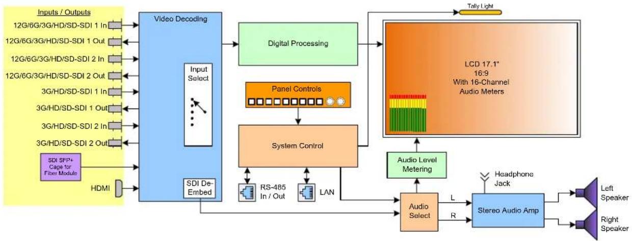
Figure 3-3: vMON-270-4K, vMON-270-8K Block Diagram

flowchart
graph TD
    A["Inputs / Outputs"] --> B["Video Decoding"]
    C["12G/6G/3G/HD/SD-SDI 1 In"] --> B
    D["12G/6G/3G/HD/SD-SDI 1 Out"] --> B
    E["12G/6G/3G/HD/SD-SDI 2 In"] --> B
    F["12G/6G/3G/HD/SD-SDI 2 Out"] --> B
    G["3G/HD/SD-SDI 3 In"] --> B
    H["3G/HD/SD-SDI 3 Out"] --> B
    I["3G/HD/SD-SDI 4 In"] --> B
    J["3G/HD/SD-SDI 4 Out"] --> B
    K["SDI 5FP+ Cage for Fiber Module"] --> L["HDMI"]
    L --> M["SDI De-Embed"]
    M --> N["Input Select"]
    N --> O["Digital Processing"]
    O --> P["LCD 27" 16:9 With 16-Channel Audio Meters"]
    P --> Q["Panel Controls"]
    Q --> R["System Control"]
    R --> S["RS-485 In / Out"]
    R --> T["LAN"]
    S --> U["Audio Level Metering"]
    T --> U
    U --> V["Audio Select"]
    V --> W["L"]
    V --> X["R"]
    W --> Y["Stereo Audio Amp"]
    X --> Y
    Y --> Z["Headphone Jack"]
    Y --> AA["Left Speaker"]
    Y --> AB["Right Speaker"]
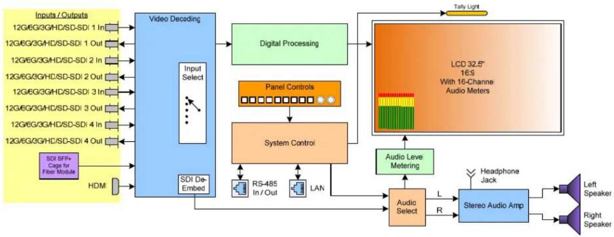
Figure 3-4: vMON-320-4K, vMON-320-8K Block Diagram
flowchart
graph TD
    A["Inputs / Outputs"] --> B["Video Decoding"]
    C["SDI SFP+ Cage for Fiber Module"] --> D["HDMI"] --> E["SDI De-Embed"]
    B --> F["Input Select"]
    F --> G["Digital Processing"]
    G --> H["LCD 32.5" 16:9 With 16-Channe Audio Meters"]
    H --> I["Audio Level Metering"]
    I --> J["Audio Select"]
    J --> K["Stereo Audio Amp"]
    K --> L["Headphone Jack"]
    K --> M["Left Speaker"]
    K --> N["Right Speaker"]
    F --> O["Panel Controls"]
    O --> P["System Control"]
    P --> Q["RS-485 In / Out"]
    P --> R["LAN"]
    Q --> S["Tally Light"]
    R --> S

- Reproduction
- Customer Support
- Other Technologies and Products
- Last Update
- TABLE OF CONTENTS
- Introduction
- Overview
- Safety
- Instructions
- Important:
- Screen Maintenance
- Safety Symbols
- WARNING:
- Mounting
- Heat Dissipation
- Important
- Sympathetic Vibration
- Electrical Interference
- Power
- Compliance
- FCC
- ICES-003
- CHAPTER 2: Local Operation
- Operation
- Front Panel
- Rear Panel
- Front Panel Control Operations
- Menus and Options
- Menu Navigation
- Main Menu
- Status Menu
- Video Payload ID/HDMI Status Menu
- Configuration Menu
- Function Menu
- Source Menu
- The following selections are available only if Quad input mode is selected:
- Color Menu
- Image Menu
- Scope Menu
- Assist Menu
- Marker Menu
- Audio Menu
- CC Menu
- UMD Menu
- System Menu
- Commonly Used Setups
- Input Source Selection, Single Picture Mode
- Input Source Selection, Quad Split Mode
- Input Source Selection, SDI SQD/2SI
- Configuration Settings
- Function Key Settings
Brand : Wohler
Model : vMON-270-8K
Category : Screen