M-32 AD Pro - Audio/video converter RME - Free user manual and instructions
Find the device manual for free M-32 AD Pro RME in PDF.


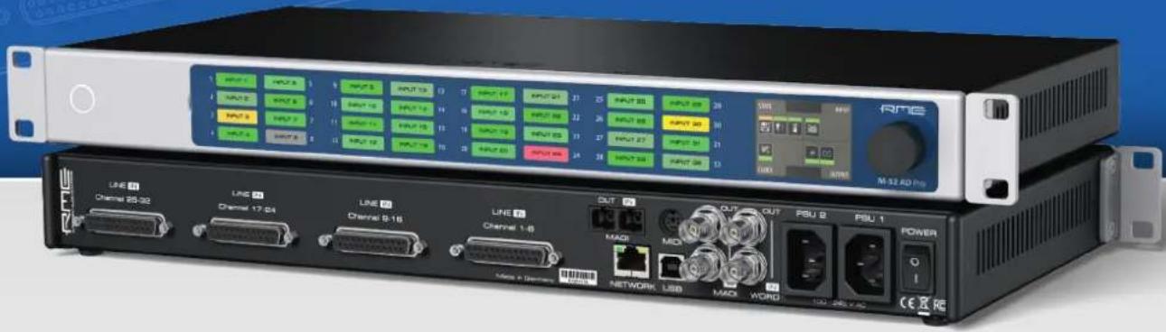
| Product Type | 32-Channel 192 kHz A/D Converter with MADI & AVB I/O |
| Dimensions (W x H x D) | 440 x 44 x 243 mm (17.3 x 1.7 x 9.6 in) |
| Weight | 2.8 kg (6.2 lbs) |
| Power Supply | Dual internal 60W, 90-264V AC, auto-ranging, with IEC C14 inlets |
| Power Consumption | Typical 25W, standby 0.5W |
| Analog Inputs | 32 channels, servo-balanced, via 4x 25-pin D-sub (Tascam pinout) |
| Digital I/O | MADI: optical (SC) and coaxial (BNC), each up to 64 channels; AVB: 4 streams in/out up to 16 ch each |
| Sample Rates | 32, 44.1, 48, 88.2, 96, 176.4, 192 kHz |
| Bit Depth | 24-bit |
| AD Converter Performance | SNR up to 120.7 dBA (A-weighted), THD+N < -108 dB at -1 dBFS |
| Adjustable Input Level | Per channel: +13, +19, +24 dBu @ 0 dBFS |
| Remote Control | MIDI over DIN/MADI, AVDECC, web remote via Ethernet or USB |
| Front Panel | Display with encoder, 32 custom label fields with peak/RMS metering, status ring |
| Clock | Internal master, word clock I/O (BNC), SteadyClock FS with ICC |
| Redundancy | Dual power supplies, MADI auto input failover, port mirroring |
| Presets | 15 user presets + 1 factory default (preset 16) |
| Maintenance | Firmware update via web remote, replaceable channel label sheet |
| Safety | Do not open; no user serviceable parts; refer to qualified personnel |
| Accessories Included | 2 rack mount brackets, screws, 2 power cords, 5 customizable label sheets, printed manual |
Frequently Asked Questions - M-32 AD Pro RME
User questions about M-32 AD Pro RME
0 question about this device. Answer the ones you know or ask your own.
Ask a new question about this device
Download the instructions for your Audio/video converter in PDF format for free! Find your manual M-32 AD Pro - RME and take your electronic device back in hand. On this page are published all the documents necessary for the use of your device. M-32 AD Pro by RME.
USER MANUAL M-32 AD Pro RME
32-Channel 192 kHz A/D Converter with MADI & AVB I/O
User's Guide
RME M-32 AD Pro User's Guide
Table of Contents
- Safety Precautions.... 1
- Introduction.... 2
2.1. Firmware Update.... 2
2.2. Use of the Display and Encoder.... 3
2.2.1. Sections....3
2.2.2. Tabs....4
2.3. Status Indicator Color Chart....4
- Hardware....5
3.1. Hardware Specifications 6
3.2. Package Contents....6
3.3. Power On 6
3.4. Standby Switch 7
3.5. Ring Illumination 7
3.6. Channel Labels with Integrated Metering....8
3.7. Meter Backlight Color and Intensity Reference 8
3.8. Replacing the Channel Labels 8
3.9. Control Section 9
3.10. Power Supplies 9
3.11. Analog Line Input Connectors.... 10
3.12. Analog Line Levels 10
3.12.1. AD Converter Specifications.... 11
3.13. MADI Connectors ...... 11
3.14. Network Connection.... 12
3.15. MIDI Connector....12
3.16. Word Clock 13
3.17. USB 2.0 Type B Jack....13
3.18. Mounting the Rack Adapter Brackets.... 14
- Accessories 15
- AVB Connectivity 16
5.1. Identifying a Device Remotely 16
5.2. Changing the Device Name ...... 17
5.3.AVB Stream Size 17
5.4.AVB Network Latency 17
5.4.1. Adjusting the network latency 18
- Quick Start (MADI) 19
- Warranty and Support 21
7.1.Warranty 21
7.2.Support....21
7.3.Support Contacts 21
- STATE Section 23
8.1. Power State 23
8.1.1. Notification of Single Power Failure 23
8.2.Presets 24
8.2.1. Saving Presets 24
8.2.2. Loading Presets 25
8.2.3. Loading Factory Default Settings.... 26
8.3.Device Lock 26
8.3.1. Locking the Device....26
8.3.2. Unlocking the Device 26
8.4. Front Panel Illumination 27
8.4.1. Dark Mode....27
8.4.2. Changing the Meters to Peak or RMS Mode. 28
8.4.3. Persistent Clipping Notifications 29
8.4.4. Metering of Digital Input Signals 29
8.5. Remote Control Overview....30
8.5.1. Finding the Device on a Network 30
8.5.2. Web Remote 31
8.6.Device Information 33
- INPUT Section 34
9.1.Analog Inputs. 34
9.1.1. Adjusting the Input Line Level 34
9.1.2. ADC Converter Mute 35
9.2.MADI Input 35
9.2.1.MADI at High Sample Rates 35
9.2.2. Connecting Two Identical MADI Signals for Redundancy.... 36
9.3.AVB Input Streams 37
9.3.1. Change AVB Input Stream Size 37
- OUTPUT Section....39
10.1.MADI Outputs 40
10.1.1. Setting the Output Channel Format and Frame Pattern 40
10.1.2. Routing Signals to the MADI Outputs 40
10.1.3. MADI Daisy Chains 41
10.1.4. MADI Port Mirroring.... 41
10.2.AVB Output Streams 42
10.2.1. Change AVB Output Stream Size 42
- CLOCK Section 44
11.1. Clock status.... 44
11.2. Master Clock 44
11.2.1. Selecting a Master Clock 45
11.3. Sample Rates Overview 45
11.3.1. Slave Mode....46
11.3.2. Number of Channels 47
11.3.3. Selecting a Sample Rate 48
11.3.4. Effects of Sample Rate Changes on Existing Routing.... 48
11.4. Set Word Clock Output to Single Speed 48
- Annex....50
12.1. MIDI Implementation Chart 50
12.1.1. Basic SysEx format 50
12.1.2. Message Types 50
12.1.3.Table 51
12.2. Declarations of conformity 55
12.2.1. CE Compliance....55
12.2.2. FCC Compliance 55
12.2.3. Note on Disposal 55
1. Safety Precautions
 WARNING WARNING | |
 | DO NOT OPEN DEVICE - RISK OF ELECTRIC SHOCKThe unit has non-isolated live parts inside. No user serviceable parts inside.Refer service to qualified service personnel. |






2. Introduction
Thank you for purchasing the M-32 AD Pro.
The M-32 AD Pro is a versatile multichannel format converter with exceptional audio quality across each of its channels. State-of-the-art components from audiophile grade converters have been carefully aligned to fit into a compact, 1 HU 19" rack device.
The device was designed to use the entire front for visual feedback on its state and configuration. A display with encoder allows to perform all configurations directly at the device. Thirty-two custom-inscribable labeling fields with backlight in shades of green, yellow, and red indicate the current signal level.
Each analog channel can be individually adjusted to three different sensitivities that are perfectly matched to the converter's range. While this is usually implemented with digital 'trims', the M-32 AD Pro does the adjustment in the analog domain, ensuring that the converter's signal to noise ratio is not reduced when adapting to common line levels.
Digital audio can be received, routed, and sent over MADI and AVB. While MADI remains the de-facto standard of point-to-point audio transmission, AVB has been chosen as a robust network solution based on open standards. It allows simultaneous transmission of all 32 analog channels at 192 kHz sampling frequency over a single network cable.
Various remote control protocols allow the device to be configured seamlessly via MIDI over MADI, MIDI, IEEE 1722.1 AVDECC, and a web interface accessible by network or USB connection with a browser.
The following manual provides a detailed explanation of features and their proper use. Please read the safety instructions carefully.

Features described in this manual can change when the device firmware is updated. It is therefore recommended to refer to the latest version of the manual available online.
Although the contents of this manual have been thoroughly checked for errors, RME can not guarantee that it is correct throughout. RME does not accept responsibility for any misleading or incorrect information within this guide. RME reserves the right to change specifications at any time without notice.
2.1. Firmware Update
New and improved features for this device, as well as bug fixes, are published on the RME website in the download section as a firmware update. The update is provided as a compressed file with a .swu extension and can be uploaded via web remote over USB or network.
To update the M-32 AD Pro:
- Connect the device by USB or network cable and open the Web Remote.
See: Section 8.5.1, "Finding the Device on a Network" - Download the current firmware from the RME website.
- Unpack the compressed file.
- Open the ⚙ Settings in the Web Remote.
RME M-32 AD Pro User's Guide
Firmware Update
Firmware version: fw_1.1.0rc1_v67 m32da 20180929-10H54M (v67)

Select .swu Firmware File
Start Firmware Update
-
Within the Firmware Update section, press the Select .swu Firmware File button and locate the unpacked file.
-
Press Start Firmware Update.

The unit retains all settings, including presets, when the firmware is upgraded.
2.2. Use of the Display and Encoder
The M-32 AD Pro can be controlled directly at the unit. For this purpose, a display and an encoder provide access to all features.
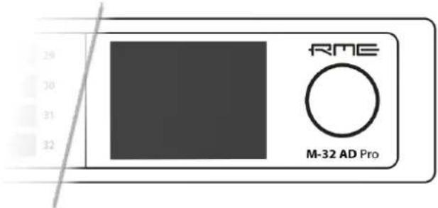
- Rotating the encoder when the standby screen is shown highlights one of four sections.
- Pushing the encoder when the screen is idle activates the previously active tab.
- Pushing the encoder when a section is highlighted opens the corresponding section.
2.2.1. Sections
All control items are categorized into four sections:
• STATE for general settings
- INPUT for audio input related settings
- OUTPUT for audio output related settings and routing
- CLOCK for digital clock related settings
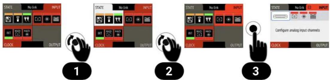
flowchart
graph TD
    A["1: State/No link INPUT"] --> B["2: State/No link INPUT"]
    B --> C["3: State/No link INPUT"]
    C --> D["3: Configure analog input channels"]
To access the INPUT section:
RME M-32 AD Pro User's Guide
- Rotate the encoder to highlight the "STATE" section
- Rotate the encoder to highlight the "INPUT" section
- Push the encoder to open the "INPUT" section.
2.2.2. Tabs
The STATE, INPUT and OUTPUT sections are further divided into tabs, which are shown when the section is opened. Upon opening one of the four sections, a white cursor with a surrounding blue line is shown to navigate between tabs and settings.
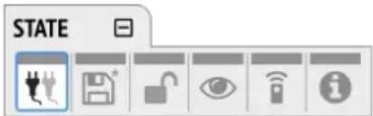
To close the section, move the cursor onto the minimize-icon and confirm by pressing the encoder.
2.3. Status Indicator Color Chart
Notifications on this device have been optimized for different screen sizes. They are unified across the device display and the web remote and feature a color bar that indicates the current state at a glance.
The following table shows the possible status indicator colors for reference.
| Status Color Description | ||
| Warning red Requires a configuration change or matching external signal. | ||
| Notice yellow There is a potential issue. | ||
| Notice (in progress) yellow with dots There is a temporary issue that should resolve automatically. | ||
| No Routing light green In output section: Output is sending an empty signal. | ||
| Issues with Input light green On standby screen in output section: Output is working, but issues with input. | ||
| Good green Everything is working as expected. | ||
| Inactive grey Feature is not monitored or disabled. | ||
3. Hardware
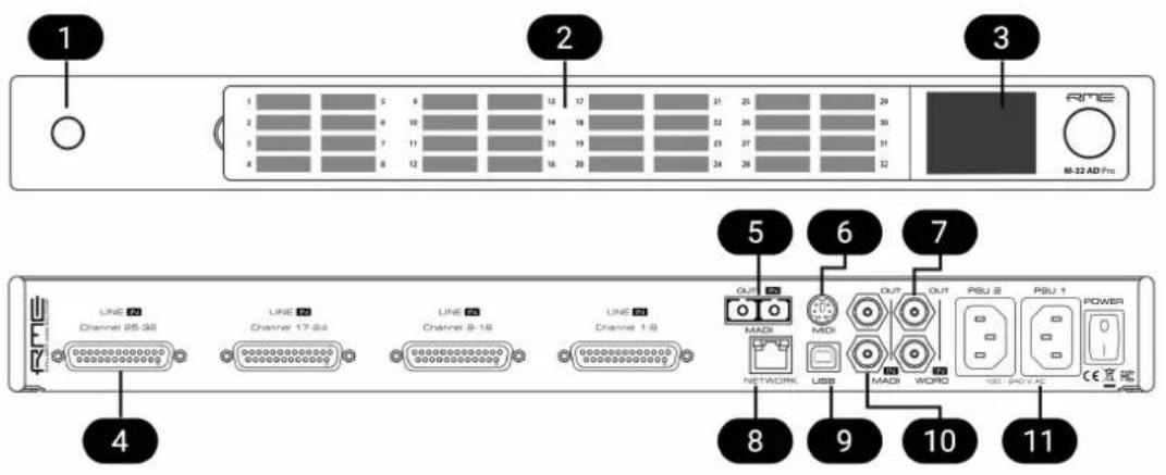
1 Section 3.4, "Standby Switch"
2 Section 3.6, "Channel Labels with Integrated Metering"
3 Section 3.9, "Control Section"
4 Section 3.11, "Analog Line Input Connectors"
5 Section 3.13, "MADI Connectors"
6 Section 3.15, "MIDI Connector"
7 Section 3.16, "Word Clock"
8 Section 3.14, "Network Connection"
9 Section 3.17, "USB 2.0 Type B Jack"
10 Section 3.13, "MADI Connectors"
11 Section 3.10, "Power Supplies"
3.1. Hardware Specifications
RME M-32 AD Pro
EAN 42 6012336 321 5
Dimensions 440 x 44 x 243 mm (17.3 x 1.7 x 9.6 inches)
Weight 2.8 kg (6.2 lbs)
Package 560 x 315 x 115 mm (22.1 x 12.4 x 4.5 inches)
Conformity CE, FCC, WEEE, RoHS
Power supplies Dual 60W 90-264V AC
Power consumption typ. 25W, standby 0.5W
3.2. Package Contents
The package of the M-32 AD Pro contains the following items:
• M-32 AD Pro
- two rack mount brackets
- four screws for rack mount brackets
- two power cords
- 5 customizable channel labels
- printed manual

If any item is missing from a factory-sealed package, please contact support immediately.
3.3. Power On
The M-32 AD Pro has a power off switch at the rear and a standby switch at the front.
Perform the following steps to power on the M-32 AD Pro:
- Ensure either or both power inlets are properly connected to a power source.
- Toggle the mains switch at the back of the device to position I (down) The power indicator will light up in red (Standby) or white (On). This depends on the state of the device before the rear switch was toggled or the power cord removed.
- If the device is in standby mode, push the standby switch to boot the device.

The M-32 AD Pro features a dark mode which deactivates some or all lights of the front panel. This can be used to let the device appear powered off when it is in fact powered on. A short push on the standby switch or the encoder deactivates this mode temporarily.
3.4. Standby Switch
natural_image
Simple geometric diagram with a circle inside a rectangle and a diagonal line (no text or symbols)The standby switch is used to power off the device when it is not in use. While in standby mode, the device is completely powered down except for a red ring illumination. No signals are processed or passed on.

Possible actions:
- When the device is in standby mode, a short push on the standby switch boots the device.
- When the device is powered on, push and hold the standby switch for several seconds in order to power down the device.
3.5. Ring Illumination
The following illumination patterns are possible:

No illumination
• There is no power at either of the two AC inlets.
- The power switch at the rear of the device is set to 'Off'.
• Dark mode has been activated.

Permanent red illumination
- The device is powered off but is receiving power at either one of the AC inlets.

Permanent white illumination
- The device is powered on and all systems are working without warning.

Alternating red/white illumination
- Something is not working properly. This is triggered when one of the four display sections: STATE, INPUT, OUTPUT, or CLOCK signals a warning.
3.6. Channel Labels with Integrated Metering
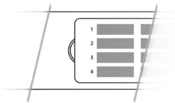
The use of customized channel labels helps in recurring and permanent installations. They inform the user where the analog connections terminate.
The M-32 AD Pro features 32 fields on the front panel, one for each analog input. Integrated backlight in shades of green, yellow, and red represents the current level for each channel.
3.7. Meter Backlight Color and Intensity Reference
The following table describes the signal level represented by the backlight color. Each value corresponds to full scale, which is equivalent to the reference level of the corresponding input.
| Color Color name dBFS | ||
 | Green | -54 (barely visible in low light)-40 (barely visible in daylight)-20 (bright green) |
 | Yellow | -5 (strong yellow) |
 | Orange | -4 |
 | Red | -1 |
 | Red flashing fast | 0 (at least three consecutive samples) |
 | Red flashing slow | input muted |
3.8. Replacing the Channel Labels
No tools are required to replace the channel labels. All 32 labels are printed or written onto a single sheet.
Perform the following steps to replace the labels:
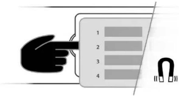
- On the left side of the cover, place your fingertip into the recess and gently pull the cover towards you.
RME M-32 AD Pro User's Guide
-
Remove the current label sheet that is held between cover and device.
-
Place a new label sheet onto the cover.
-
Put the cover back into its place, aligning the centered metal plate first. It snaps into place magnetically.

It is possible to prepare your own paper cutouts in case you frequently need to label the fields. A PDF template is available upon request from your support. When choosing the paper type, ensure that its thickness allows sufficient light to pass through.
3.9. Control Section
The M-32 AD Pro can be configured completely at the device.
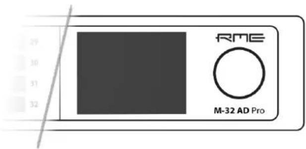
To do so, the a TFT display shows a menu. The adjacent encoder knob is used to navigate and change settings.

The encoder can be pushed in order to activate an item,

and rotated left and right in order to select an item.

If the device is powered on but the display shows no content, dark mode may be active. Rotate the encoder to temporarily bypass this mode and show the display.
3.10. Power Supplies
The M-32 AD Pro has two internal power supplies (PSUs) that are connected via IEC C14 inlets labeled "PSU 1" and "PSU 2" at the rear of the device. Both are hi-performance switch mode power supplies that accept 90V to 264V AC. They are short-circuit-proof, have an integrated line-filter, are fully regulated against voltage fluctuations, and suppress mains interference.

The inlets are labeled in the sequence they appear when looking from the front of the device. This helps identifying the active power source on the display.
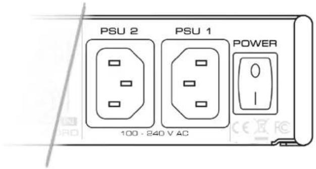
The power switch next to the two inlets internally disconnects the line connection of the C14 inlets to the power supplies. Ground and neutral will remain connected.
Lockable IEC plugs
The inlets can be used with special IEC power cords that have a lockable connector. Please contact a local distributor to purchase these power cords if needed.
3.11. Analog Line Input Connectors
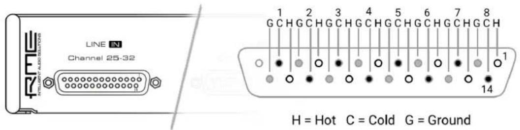
The rear of the M-32 AD Pro features four 25-pin D-sub connectors labeled "LINE IN" with Tascam®-pinout.
These analog inputs are servo-balanced, allowing balanced and unbalanced signals to be connected without a difference in level.

When using unbalanced connections, be sure to connect pin 3 (negative/"cold") to pin 1 (ground), to avoid noise from the unconnected pin 3 input.
3.12. Analog Line Levels
The M-32 AD Pro can be adjusted to the following reference levels:
| Reference 0 dBFS Headroom at | +4dBu | Other RME devices |
| +24 +24 dBu 20 dB - | ||
| +19 +19 dBu 15 dB LoGain | ||
| +13 +13 dBu 9 dB +4 dBu |

When set to +24, analog inputs comply with RP 155:2014 - SMPTE Recommended Practice.
3.12.1. AD Converter Specifications
Line In 1-32:
- Resolution: 24 bit
- Input level switchable per channel +24 dBu, +19 dBu, +13 dBu @ 0 dBFS
- Inputs AC coupled, fully symmetrical signal path (servo-balanced)
- Signal to Noise ratio (SNR) @ +24 dBu, 44.1 kHz: 117.0 dB RMS unweighted, 120.7 dBA
• Signal to Noise ratio (SNR) @ +19 dBu: 116.3 dB RMS unweighted, 119.9 dBA
• Signal to Noise ratio (SNR) @ +13 dBu: 114.7 dB RMS unweighted, 118.3 dBA - Frequency response @ 44.1 kHz, -0.1 dB: 5 Hz – 20.5 kHz
- THD @ -1 dBFS: < -111 dB, < 0.00029%
• THD+N @ -1 dBFS: < -108 dB, < 0.00039 %
• Channel separation: > 110 dB
3.13. MADI Connectors
The rear of the M-32 AD Pro features independent optical and coaxial MADI (AES10-2003) I/O.
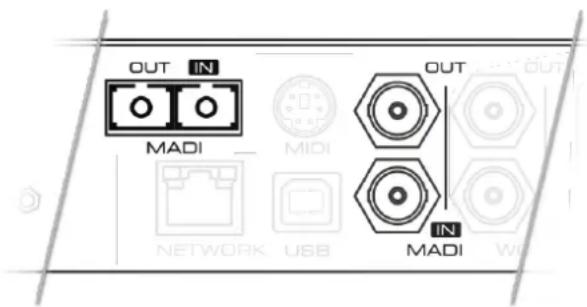
Each input receives up to 64 audio channels. Auto Input (see Section 9.2.2, "Connecting Two Identical MADI Signals for Redundancy") can be activated to treat both inputs as one.
The optical "subscriber" or "square" connector (SC, IEC 61754-4) accepts both simplex and duplex multimode (MM) fibers of 50 and 62.5 m diameter and up to 2km length.
The coaxial BNC connector accepts coaxial cables with 75Ω impedance.
On the device, the characteristics and state of the signal at either input can be inspected in the INPUT section.
The presence or loss of a signal at either port is indicated on the standby screen if
- the input port is selected as clock master, or
- its audio channels are routed in the OUTPUT section.
When using the web remote, the characteristics and state of the signal at either input can be inspected in the CLOCK section.
3.14. Network Connection
On the rear of the M-32 AD Pro, an RJ45 connector labeled NETWORK provides a connection to ethernet. Two link speeds are supported: 100 Mb/s and 1 Gb/s.
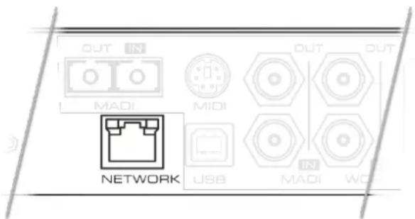
A green LED (left) signals network traffic (blinking). A yellow LED (right) signals a successful link.
Both straight and crossover cables can be used (Auto MDI-X). Cable lengths of up to 100m are supported when using Cat 5e or higher classification.
The network port is used to send and receive:
- up to four AVB audio streams when connected to AVB switches and endpoints,
- remote status/control with AVDECC, and
- remote status/control with HTTP over IP routed networks.
The current link state is also shown on the display of the M-32 AD Pro. A small network port icon between the STATE and INPUT tabs can display the following states:
STATE

INPUT
Link State Icons
Description

No link - cable not connected

Negotiating link with other endpoint

Successful link with speed of 100 MBit/s

Successful link with speed of 1 GBit/s
3.15. MIDI Connector
The M-32 AD Pro can be controlled with MIDI SysEx commands from either a physical MIDI connection or a MIDI over MADI signal. A MIDI breakout cable can be purchased from your RME dealer.
RME M-32 AD Pro User's Guide
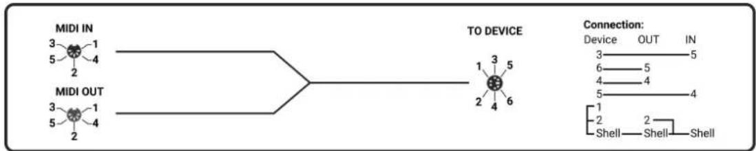
flowchart
graph LR
    A["MIDI IN"] --> B["TO DEVICE"]
    C["MIDI OUT"] --> B
    B --> D["Connection: Device OUT IN"]
    style A fill:#f9f,stroke:#333
    style C fill:#f9f,stroke:#333
    style D fill:#ccf,stroke:#333
MIDI Breakout Cable Wiring Diagram

The M-32 AD Pro does not serve as a MIDI to/from MIDI over MADI converter. It does not pass on incoming MIDI signals except for SysEx remote control information.
3.16. Word Clock
Word clock can be sent and received via 75 Ω coaxial cabling at the corresponding BNC connectors. The cable length should not exceed 100 m (330 ft).
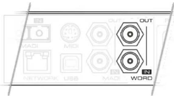

The input is terminated with 75 Ω internally. To pass on the word clock to other devices, use the word clock output. Do not connect a T-adapter to the word clock input.
The state of an incoming word clock signal can be accessed in the CLOCK section.
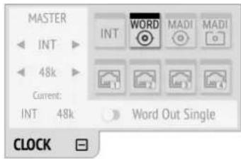
Possible States:
- A green indicator shows that the signal is currently in sync with the chosen clock master.
- An orange indicator means that a word clock is received but is not in sync.
- A red indicator means that word clock is chosen as master, but a signal is not present or has a different sample rate than the chosen one.
3.17. USB 2.0 Type B Jack
The USB jack at the rear of the M-32 AD Pro provides an alternative connection method for web remote control when a network connection is not available.
RME M-32 AD Pro User's Guide
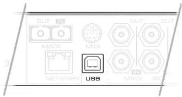
When connecting the M-32 AD Pro with a standard ("printer") USB 2.0 cable to a current Microsoft Windows™ or Apple macOS™ operating system, a network adapter will be automatically installed. This does not require additional drivers. The device can then be remotely controlled by opening the URL http://172.20.0.1.

The USB port cannot be used to stream audio signals.
3.18. Mounting the Rack Adapter Brackets
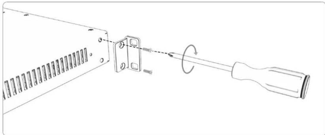
When the device should be mounted in a 19" rack, the rack adapter brackets must be mounted first.
natural_image
Technical line drawing of a mechanical component with a screwdriver and internal parts, showing a rotational motion (no text or symbols)Mount each bracket with two screws using a Philips PH-1 screwdriver.

Do not use screws other than the ones included. Using longer screws may result in the internal damage of the device!

Never insert the screws without the rack adapter bracket. This can damage of the device!
4. Accessories
RME offers several optional components for the M-32 AD Pro:
Part Number Description
Analog breakout cables
Al25-8XPro3 Analog breakout cable 25-pin D-sub to 8 x XLR female, 3 m (9.9 ft)
Al25-8XPro5 Analog breakout cable 25-pin D-sub to 8 x XLR female, 5 m (16.4 ft)
Al25-8XPro10 Analog breakout cable 25-pin D-sub to 8 x XLR female, 10 m (33 ft)
19" XLR breakout panels
DTOX-16 I 16x XLR Input to 2x D-sub
MADI Optical cables
MADI1S MADI Optical Network Cable, Simplex, 1m (3.3 ft)
MADI3D MADI Optical Network Cable, Duplex, 3m (9.9 ft)
MADI6D MADI Optical Network Cable, Duplex, 6m (19.8 ft)
MADI10D MADI Optical Network Cable, Duplex, 10m (32.8 ft)
MADI20D MADI Optical Network Cable, Duplex, 20m (65.6 ft)
MADI50D MADI Optical Network Cable, Duplex, 50m (164 ft)
Third party accessories available from independent global retailers:
Optional power cords with locking mechanism
Manufacturer Part Number Description
Schurter 6051.2032 CN CORDSET 10A 2.0M V-LOCK
Schurter 6051.2003 EU CORDSET 10A 2.0M V-LOCK
Schurter 6051.2031 JP CORDSET 10A 2.0M V-LOCK
Schurter 6051.2008 UK CORDSET 10A 2.0M V-LOCK
Schurter 6051.2001 US CORDSET 10A 2.0M V-LOCK
5. AVB Connectivity
Network Control
The M-32 AD Pro is an AVB endpoint device that can be configured with the IEEE Standard for Device Discovery, Connection Management, and Control Protocol for IEEE 1722™ Based Devices, in short: AVDECC.

This device does not provide an AVDECC controller for connected devices. To establish an AVB connection between devices, a separate controller is required.
There are several AVDECC controllers available for download from different manufacturers that support the commands required to
- identify the device,
- adjust its sample rate and clock source, and
- create connections to or from it.
The RME Digiface AVB includes an AVDECC controller.
Many other configuration options of the M-32 AD Pro are at this time not implemented in generic AVDECC controllers. Both the control on the device and its web remote can be used to configure additional options.

An AVDECC controller can optionally acquire the device. This means that the M-32 AD Pro is no longer configurable by display or web remote until the acquisition is released.
Audio Streaming
The M-32 AD Pro has four outgoing and four incoming stream ports. Each one can be configured to contain 4, 8, 12 or 16 audio channels.
In order to establish a connection (stream) between two AVB devices, the following conditions must be fulfilled:
- There must be a physical connection between the devices.
- All switches between the devices must be certified AVB switches (or compatible).
- An AVDECC Controller is required to find the devices and to connect them.
- The stream port size must be identical at sender and receiver.

A stream between two AVB devices is deterministic, has a fixed latency, and reserved bandwidth.
5.1. Identifying a Device Remotely
When several M-32 AD Pros are connected to the same network, each device has its own remote control. To quickly reveal which device is currently being controlled, the HTTP remote and any AVDECC controller can send an Identify command. This triggers an animation of the front panel level meters of the corresponding device.
To start device identification with the web remote:
- Open an M-32 AD Pro web remote in a browser
- Press the identify 🔔 icon. The front panel level meters of the controlled device will show an animation.

Depending on the controller, the animation may persist infinitely or stop after a short period of time.
5.2. Changing the Device Name
A custom name can be assigned to the device. It is used to identify the AVB entity with AVDECC controllers. It also allows the access to the web remote without using the IP address on Apple macOS™ computers.

The device name is stored to and recalled from presets. It is not affected by firmware updates.
Changing the device name is only possible via web remote or AVDECC controller.
To change the device name:
- Connect the device by USB or network cable and open the web remote.
Section 8.5.1, "Finding the Device on a Network"
- Open the ⚙ Settings in the web remote.
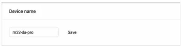
- Type a new name into the text field and press Save. The name is immediately applied.
5.3. AVB Stream Size
In an AVB network, a stream describes a connection between a talker and one or more listeners. It consists of a fixed number of audio channels at a fixed sample rate. Once a stream is connected, each AVB switch along its way ensures that the audio channels can pass in time, with a higher priority than other network traffic.
The M-32 AD Pro supports a total of four streams. Each stream can have a size of 4, 8, 12, and 16 channels. The most common stream size is 8 Channels.

When using the AVB features of Apple macOS ^™ , ensure that all streams have a size of 8 channels before acquiring the M-32 AD Pro.
5.4. AVB Network Latency
All devices in an AVB network share the same time. This allows the sending device (talker) to specify the precise point of time when its audio samples should be played out at the receiver side (listener). This is achieved by adding an offset to the current time and sending the resulting timestamp with each sample transmitted. The timestamp is called "presentation time" and has nanosecond precision. For comparison, a single sample at 48 kHz has a duration of over 20800 ns.
The receiver compares the incoming presentation time of each sample to the current time and buffers the sample until the presentation time is has come.
The offset (maximum transit time) is specified by the AVB standard as 2 ms for class A traffic, which is enough time for the signal to pass through a very large network under full load with up to seven 100 MBit/s switches along the way. By default, most AVB products will use this offset. In smaller networks with less hops or 1 GBit/s link speed, the offset can be adjusted to lower values, such as 0.3 ms, 0.6 ms or 1 ms. In the event that the chosen offset is too low, the listener detects that the requested presentation time has already passed and the audio data is discarded.
The M-32 AD Pro acts both as a talker with a specified offset of 2 ms, adjustable down to 0.3 ms, and as a listener - where the latency depends on the talker.

In AVB networks, the latency is always specified by the talker and guaranteed by the listener - with nanosecond accuracy. This behavior is plug and play and does not require any user interaction or monitoring.
5.4.1. Adjusting the network latency
The default presentation time offset of 2 ms for outgoing streams can be changed when lower latencies are required.

Reducing the offset to a lower value can prevent audio to be played out depending on the network.
This setting can only be accessed on the web remote.
To adjust the presentation time offset:
- Connect the device by USB or network cable and open the web remote.
Section 8.5.1, "Finding the Device on a Network"
- Open the ⚙ Settings .
- Activate Expert Settings.

Expert Settings
AVB Advanced Settings
Presentation Time Offset
2 ms
- Choose a new Presentation Time Offset in the drop down menu. It is immediately applied.

Changing the presentation time offset briefly interrupts all incoming and outgoing AVB streams.
6. Quick Start (MADI)
Follow this procedure to get running quickly!
- Load Preset 16 (Factory settings) from the STATE section
- In the CLOCK section, choose a sample rate and verify that the device is clock master or that the chosen clock source is in sync.
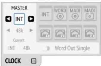
- After connecting an analog signal, adjust its reference level as needed in the INPUT section
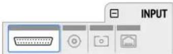
- Open the tab of the preferred digital output in the OUTPUT section and choose "Analog 1-32" as source.
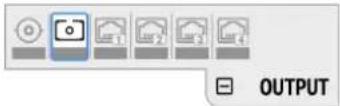
done!
Further steps to enhance your start:
State
• Section 8.1.1, "Notification of Single Power Failure"
• Section 8.2.2, "Loading Presets"
• Section 8.3.1, "Locking the Device"
• Section 8.4.1, "Dark Mode"
• Section 8.5.2, "Web Remote"
• Section 2.1, "Firmware Update"
Input
• Section 9.1.2, "ADC Converter Mute"
- Section 9.2.2, "Connecting Two Identical MADI Signals for Redundancy"
• Section 9.3.1, "Change AVB Input Stream Size"
Output
• Section 10.1.2, "Routing Signals to the MADI Outputs"
• Section 10.2.1, "Change AVB Output Stream Size"
- Section 10.1.1, "Setting the Output Channel Format and Frame Pattern"
7. Warranty and Support
7.1. Warranty
Each individual M-32 AD Pro undergoes comprehensive quality control and a complete test before shipping. The usage of high grade components should guarantee a long and trouble-free operation of the unit.
If you suspect that your product is faulty, please contact your local retailer. Do not disassemble the device by yourself as it may get damaged. It has been sealed with tamper-evident material, and your warranty is void if those seals have been damaged.
The distributor grants a limited manufacturer warranty of 6 months from the day of invoice showing the date of sale. The length of the warranty period is different per country. Please contact your local distributor for extended warranty information and service. Note that each country may have regional specific warranty implications.
In any case warranty does not cover damage caused by improper installation or maltreatment - replacement or repair in such cases can only be carried out at the owner's expense.
No warranty service is provided when the product is not returned to the local distributor in the region where the product had been originally shipped.
The distributor does not accept claims for damages of any kind, especially consequential damage. Liability is limited to the value of the M-32 AD Pro. The general terms of business drawn up by the distributor apply at all times.
7.2. Support
Please ensure that you are using the latest firmware before contacting support.
In many cases, the user forum at http://forum.rme-audio.de provides help with a simple search for relevant keywords.
If the problem cannot be solved by any of the aforementioned methods, please have your serial number at hand and contact and your local dealer or distributor. A complete list of distributors can be found on the RME website.
7.3. Support Contacts
Additionally, the following global service centers can provide support assistance:
Europe
Audio AG, Germany
support@rme-audio.de
Synthax U.K.
info@synthax.co.uk
Asia/Australia
RME Trading Ltd., Hong Kong
support@rme-trading.hk
Americas
Synthax Inc., U.S.A.
tech.support@synthax.com
Global
support@rme-audio.de
8. STATE Section
The STATE section contains states and settings that are unrelated to audio I/O and clock. It can be used to configure power supply warnings, presets, dark mode, level meters, and remote control.
A warning (red) is shown when PSU redundancy is activated but only one power supply is active. A notification (orange) is shown when a preset is modified or dark mode is active.
8.1. Power State

This icon in the STATE section informs the user which of the two IEC inlets receive power. It is a realtime representation of the current power state, with an inactive power supply shown in grey.

When facing the front panel, the left power plug corresponds to the left IEC inlet at the rear.
Representation of the power states on the device
- Open the power tab in the STATE section
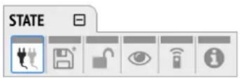
- The state of each PSU is shown as active if it receives power.
Representation of the power state on the web remote
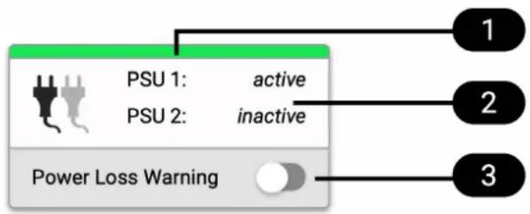
flowchart
graph TD
    A["PSU 1: active"] --> B["Power Loss Warning"]
    C["PSU 2: inactive"] --> B
    D["1"] --> B
    E["2"] --> B
    F["3"] --> B
Power tab within State section
1 Status Indicator
2 State of power supplies
3 Section 8.1.1, "Notification of Single Power Failure"
8.1.1. Notification of Single Power Failure
A warning can be displayed when one of two connected power sources fails.
On the display, a warning is signaled as an icon with a red bar:
Power loss at PSU 2
To activate the warning on the device:
- Open the power tab in the STATE section.
- Toggle the switch Redundancy to On.

The warning signals only the current state.
To activate the warning on the web remote:
- In the STATE section, activate the toggle next to Power Loss Warning.
See also: Section 8.5.2, "Web Remote"
8.2. Presets
Any change in the device configuration is persistent. After a power loss, the device will revert back to its last state. Additionally, the M-32 AD Pro can save fifteen states in presets numbered 1-15. After a preset is loaded, any change in the configuration will result in an unsaved changes state.
Representation of an unsaved preset on the device.

The internal preset storage is not affected when the device firmware is updated. Moreover, recalling the factory default preset does not delete any other saved preset.
Settings that are not saved in a Preset
The following settings are not saved in a preset:
- Auto-lock
- Lock code
- Remote control
8.2.1. Saving Presets
Up to 15 presets can be saved in the internal storage of the M-32 AD Pro.
To save a preset on the device:
- Open the preset tab in the STATE section. The cursor will highlight a preset number.
RME M-32 AD Pro User's Guide
- Push and rotate the encoder to choose a preset number.
- Push Save to save the preset.
To save a preset using the web remote:
- Open the web remote and locate the preset tab.
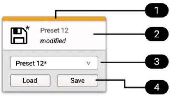
1 Status Indicator
2 Current preset and state
3 Preset drop-down menu
4 Load and save buttons
- Use the drop-down menu 3 elect a preset.
- Press the Save button 4
8.2.2. Loading Presets
Up to 15 custom presets can be loaded from the internal storage of the M-32 AD Pro.

Loading a preset cannot be undone. Ensure that any important configuration has been saved to another preset before proceeding.

The device name is part of the preset. When a preset is loaded, the device name is changed to the value stored in the preset.
To load a preset on the device:
- Open the preset tab in the STATE section (see: Section 2.2, "Use of the Display and Encoder".
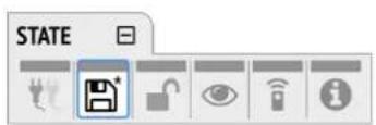
- Move the cursor to the current preset number and push the encoder.
- Rotate the encoder to choose a preset, and confirm by pushing the encoder.
- Select Load to load the preset.
To load a preset using the web remote:
- Locate the preset tab
- Use the drop-down menu 3 elect a preset.
3. Press the Load Button 4
8.2.3. Loading Factory Default Settings
The factory default settings are saved internally as Preset 16 and cannot be overwritten.
To load the factory defaults, load Preset 16.

Loading the factory defaults does not delete any saved presets. It also does not affect the lock settings in the STATE section.
8.3. Device Lock
The M-32 AD Pro can be secured against both accidental and intentional changes to its configuration. Locking the device, with or without code, protects against changes on the device itself. When locked, the display shows a lock symbol.

The device lock does not protect against changes over network or MIDI remote control protocols. The lock configuration is not stored within a preset.

A four to six digit code can be configured on the device. If this code is lost or forgotten, it is not possible for the user to unlock the device. Contact your support for assistance.
8.3.1. Locking the Device
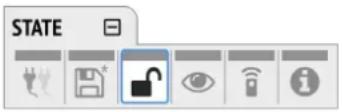
In order to lock the device, proceed with the following steps:
- Open the lock tab in the STATE section
- (optional) Set Code: enter a four to six digit code with the encoder.
- (optional) Activate the Auto Lock toggle to lock after one minute.
- (optional) Select Lock Device Now to lock immediately.

Remember or write down the code shown in SET CODE. It is not possible to unlock the device without this code. A unique secondary code (PUK) can be obtained from RME Support upon request with a proof of purchase and device serial number.
To delete the code, move the cursor on the code and push the encoder. "No code" will be displayed.
The device can only be locked and unlocked at the front panel. These controls are not accessible remotely.
8.3.2. Unlocking the Device
To unlock the device temporarily:
- Push and hold the encoder button for four seconds.
RME M-32 AD Pro User's Guide
- (if a code was set) Enter the code and choose "Done".
The device will lock again after a timeout of one minute.
To unlock the device permanently:
- Proceed as above, then
- Open the lock tab in the STATE section
- Deactivate the lock by toggling the switch to: OFF
- (optional) Move the encoder onto the lock code (if any), and push the encoder to delete it.
The device can only be locked and unlocked at the front panel. These controls are not accessible remotely.
8.4. Front Panel Illumination
The M-32 AD Pro features a unique concept for its front panel illumination, which consists of:
- A ring illumination around the standby switch that shows the overall state of the device.
- 32 channel labels with integrated backlight metering (peak or RMS).
- A display with standby screen that shows categorized warnings.
All elements have been designed to give the user thorough status feedback even from a distance. The channel backlight metering can be configured to hold over events for 5 s or infinitely. Each of the three sections can be individually switched off (dark mode).
8.4.1. Dark Mode
Each of the three front panel illumination sections can be switched off if they are not required.
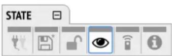
To turn off illumination on the device:
- Open the visual feedback tab in the STATE section.
- Change any of the following:
a. Power to off to turn off the standby switch ring illumination.
b. Meters to off or Dim to turn off or dim channel label backlight.
c. Display to ☐ off to turn off the display.

When any item is turned off, a notification (orange) is shown in the STATE section.
To panel illumination back on:
- Open the same menu and set the corresponding switches to to On.

To turn the front panel lighting on temporarily, just rotate or push the encoder. The panel will turn back off after five seconds.
To turn off illumination on the web remote:
RME M-32 AD Pro User's Guide
- Connect to the device remotely (see: Section 8.5.1, "Finding the Device on a Network").
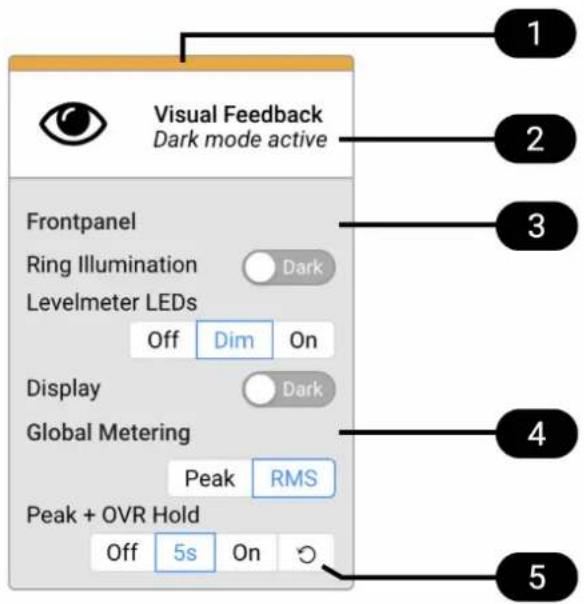
1 Status Indicator
2 State of Visual Feedback
3 Front Panel Dark Mode
4 Global Metering Options
5 Peak/Over Hold Reset
- Use the corresponding toggle switches on the web remote to switch off device lighting.
8.4.2. Changing the Meters to Peak or RMS Mode
Depending on the application, instantaneous peak level metering or a slower, averaged RMS metering can be chosen.

This is a global setting which affects both the front panel level meters and the remote control interface.
To change the metering mode on the device:
- Open the visual feedback tab in the STATE section.
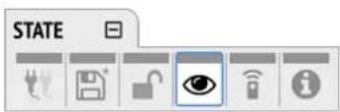
- Push the encoder on the current "Metering:" value to activate selection.
- Change the value to "Peak" or "RMS".
To change the metering mode on the web remote:
- Connect to the device remotely (see: Section 8.5.1, "Finding the Device on a Network").
-
Locate the visual feedback tab in the STATE section.
-
Push the "Peak" or "RMS" button in the global metering settings.
8.4.3. Persistent Clipping Notifications
In multi-channel applications, it can be important to find out which channel clipped. A clipping is detected when three consecutive samples are digital full scale (0 dBFS). The duration of how long a clipping ("over") event is shown can be manually changed to either five seconds or infinite.

This is a global setting which affects both the remote control and the device. On the web remote, an additional peak hold is shown in the level meters.
On the device, an over notification is signaled as a fast flashing (red) of the label backlight.
Switching over notifications on or off:
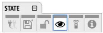
- Open the visual feedback tab in the STATE section
-
Change OVR Hold to either:
-
5s to notify for five seconds
- On to notify until manually reset
- Off to deactivate over notifications
To reset infinite full scale notifications:
- Open the visual feedback tab in the STATE section.
- Activate Reset.
8.4.4. Metering of Digital Input Signals
The digital input signals can be visually inspected to ensure that audio signals are reaching the device.
To temporarily assign the 32 front panel level meters to a digital input, open the INPUT section and choose the relevant digital input tab.
In the MADI optical and MADI coaxial tabs, two toggle switches can be pushed and held to inspect either channels 1-32 or channels 33-64.
In the AVB input tab, one toggle switch per stream can be pushed and held to inspect the relevant stream.

This feature is temporary and lasts only while the encoder is pushed. Afterwards, the front panel level meters will show the level of the analog inputs.
On the web remote, each input port can be opened and level meter indicators will appear above the channel number.
8.5. Remote Control Overview
The M-32 AD Pro can be remotely controlled. Remote control is activated by default and is not affected by preset changes or device lock.
The network controls over HTTP and AVDECC operate simultaneously. Two or more controller instances are synchronized. The MIDI control works either via DIN or is embedded into either MADI signals. Both network and MIDI control can be operated at the same time.

The remote control protocols are not protected against malicious use. When activated, the remote control server allows anyone on the network to make changes to the configuration of the device. To avoid this, secure the remote control connection externally.
8.5.1. Finding the Device on a Network
The M-32 AD Pro has two integrated network adapters (USB 2.0 and Ethernet). Both adapters can be used, individually or simultaneously, to control the device with HTTP ("web remote"). The HTTP remote control works on any IP-based network, including wireless networks.
The ethernet connection additionally supports AVDECC 1722.1 remote protocol, which requires a physical connection (cables), but does not require AVB switches. Wireless routers are not supported for AVDECC.
To enable web remote functionality over HTTP:
- Open the remote tab in the STATE section.
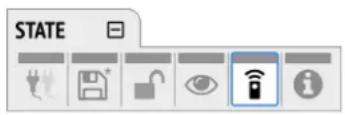
- Ensure that the HTTP Remote setting is switched to ON.
USB
When the device is connected with a USB 2.0 cable to a Apple macOS ^™ or Microsoft Windows ^™ computer, a network device is automatically installed in the background that assigns the M-32 AD Pro the following IP address:
http://172.20.0.1

Only one M-32 AD Pro can be connected via USB at a time.
Ethernet
The integrated ethernet adapter will join an IP network when connected. If no DHCP server is found, for example when connecting the M-32 AD Pro directly to a computer, an address is automatically self-assigned (in the 169.254.0.0/16 subnet).
To find out the current IP address:
- Open the remote tab in the STATE section.
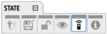
- The current IP address is displayed.
- Enter the IP address in the address bar.
Connecting to the Remote Interface without IP address
Instead of using the IP address, the device name can be entered in the browser window, followed by .local/.
By default, the name is m32-ad-pro, and the corresponding URL is therefore:
http://m32-ad-pro.local./

The length of the custom name should not exceed 63 characters. Spaces in the device name should be written as hyphens ("-") when entering the URL.

The device name is stored in a preset. Loading a preset can therefore change the device name and require a different address.
8.5.2. Web Remote
An integrated web server provides an easy-to-use remote control interface for the M-32 AD Pro. It requires a network connection from a desktop computer with a current browser version.
Compatible browsers:
- Chrome 68
• Safari 11.1 - Edge 17
- Firefox 61
or newer
Web Remote Overview
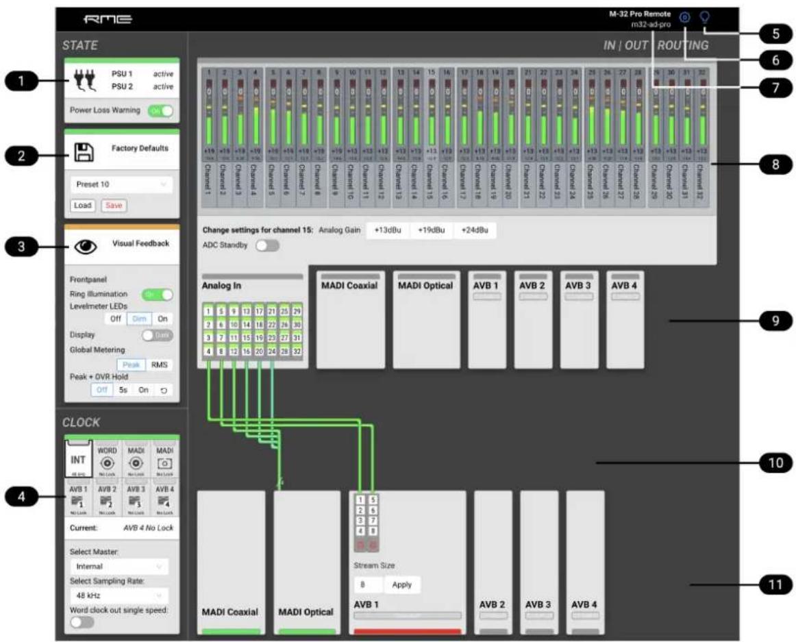
1 Section 8.1, "Power State"
2 Section 8.2, "Presets"
3 Section 8.4, "Front Panel Illumination"
4 Section 11.1, "Clock status"
5 Section 5.1, "Identifying a Device Remotely"
6 Settings: Device name, Firmware update, etc.
7 Section 5.2, "Changing the Device Name"
8 Section 9.1, "Analog Inputs"
9 Section 9, "INPUT Section"
10 Section 10.1.2, "Routing Signals to the MADI Outputs"
11 Section 10, "OUTPUT Section"
8.6. Device Information
The information tab is located in the STATE section.
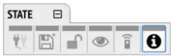
It shows the current firmware version and gPTP Grandmaster ID.
9. INPUT Section
The input section is used to inspect and configure the audio inputs of the device. A warning is displayed when an input is not present but selected as clock master, or routed to an output and is either not present or not in sync to the clock master. Related input settings, such as AVB stream size or MADI auto input, can be configured here.
9.1. Analog Inputs
The line level inputs of the M-32 AD Pro accept levels of up to +24 dBu. Each individual channel has its own line level setting of +13/+19/+24 dBu which can also be adjusted remotely. Additionally, the AD converters can be globally set to standby (mute).
At single speed sample rates, the converters are configured with short delay 'sharp' IIR filters with extremely low latencies (5 samples) and flat frequency response over the entire audible range. At higher sample rates, a short delay 'slow' filter is used to additionally optimize the impulse response. The latency increases to six samples at quad speed (176.4 kHz, 192 kHz).
In its default state, no routing exists between the analog inputs and the digital outputs. The analog signals can be routed to two MADI ports and four AVB streams at the same time.
9.1.1. Adjusting the Input Line Level
To adjust the input line level on the device:
- Open the Analog Input tab in the INPUT section
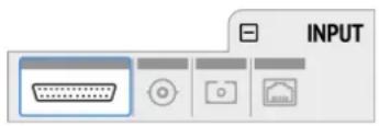
- Initially, the cursor will highlight all input channels. To accept this, rotate the encoder to move the cursor to the current reference level
- Alternatively, pressing the encoder on the channel strip allows the selection of an individual channel
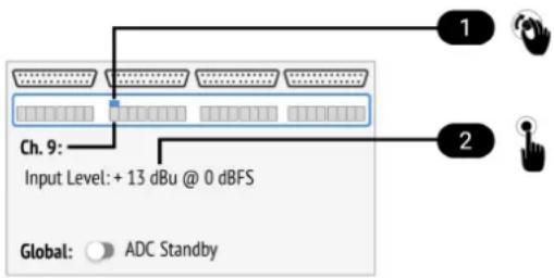
1 Cursor (current channel)
2 Input Reference Level
- Push the encoder on the current line level, then Rotate the encoder to change the setting and confirm by pushing the encoder again.
To adjust the input line level on the web remote:
-
Select either a single channel or two channels by clicking the corresponding level meter. All inputs between the two selected channels will be automatically included in the selection.
-
Press one of the corresponding buttons for +13 dBu, +19 dBu or +24 dBu. The selected value is shown within the level meter.
9.1.2. ADC Converter Mute
The analog inputs can be globally muted.
To mute the analog input channels on the device:
- Open the Analog Input tab in the INPUT section
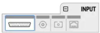
- Toggle the ADC Standby switch to ON
To mute the analog input channels using the web remote:
-
Open the web remote and locate the analog inputs.
-
Toggle the ADC Standby switch to ON.
9.2. MADI Input
The M-32 AD Pro accepts up to two MADI signals, one electrical (BNC input) and one optical (SC input).
To connect a MADI signal:
- Ensure that you have set the correct sample rate and clock source in the CLOCK section.
- Connect the cable to the corresponding input.
- Open a MADI tab in the input section to see the current LOCK and SYNC state.
- (optional) Use the device level meters to inspect the audio signal from the incoming MADI signal (see: Section 8.4.4, "Metering of Digital Input Signals").

It is best to create a routing for the MADI signal right away, before connecting the cable to the device. This activates monitoring of the corresponding input for signal loss or clock issues. If no routing exists and the signal is not set as clock reference, plugging in a MADI signal will not lead to any visible change on the device standby screen.
9.2.1. MADI at High Sample Rates
The MADI standard (AES10) allows transport of audio at sample rates beyond 48 kHz by reducing the number of available channels.
Double speed (88.2 kHz, 96 kHz)
Double speed audio signals can be transmitted and received in two different ways. Manufacturers can implement one or both modes, usually referred to as "96k frame" and "S/MUX 2" or "legacy" mode. It is important to use the same mode on both sender and receiver side because S/MUX 2 and legacy mode are not compatible. Both modes transport the audio signal transparently.
96k frame
The so-called "96k frame pattern" (AES10) can be detected at the receiver side automatically. In this mode, the frame numbers and corresponding user bits equal the number of channels submitted. The "56 Ch." setting corresponds to 28 audio channels at 88.2 kHz and 96 kHz sample rates. The "64 Ch." setting corresponds to 32 audio channels at 88.2 kHz and 96 kHz sample rates.
S/MUX 2
Sample multiplexing (or S/MUX 2) describes a method to distribute two consecutive samples onto neighboring channels. The MADI signal remains exactly the same as in single speed with 56 or 64 channels including its user-bits. The receiver decodes the audio signal by passing the samples of channel 1+2 as two consecutive samples for channel 1, samples of channel 3+4 as two consecutive samples for channel 2, and so forth. The amount of channels corresponds to the same as the 96k frame. This format cannot be automatically detected at the receiver side.
Quad Speed (176.4 kHz, 196 kHz)
Quad speed MADI does not have a standardized frame format. Therefore S/MUX 4 is used. The encoding works the same way as S/MUX 2, except that four consecutive channels are used to transport one audio channel. This reduces the available number of channels to 14 ("56 Ch." setting) or 16 ("64 Ch." setting).

When using MADI, the sample rate of the incoming MADI signal and the expected frame format of the outgoing MADI signal must be set in the device.

Since the M-32 AD Pro has two independent MADI ports, all 32 analog inputs can be sent at 192 kHz by using both ports, each carrying 16 audio channels.
9.2.2. Connecting Two Identical MADI Signals for Redundancy
The coaxial MADI input can be configured to automatically switch to an existing MADI optical signal in case the coaxial signal fails. While existing routing and clock settings from the coaxial MADI input are kept, the port's name is changed to MADI Auto Input and its icon changes to reflect the feature. The failover is seamless if the active input loses lock abruptly (e.g. one of the cables is unplugged).
The user is notified of the lost signal with a warning and redundancy can be re-established.

For a seamless failover, the two MADI signals must be identical. However, only the SYNC and LOCK states are evaluated to confirm the current input state. It is therefore possible to send two different signals to the M-32 AD Pro as long as they are in sync.
To create MADI redundancy:
- Switch on "enable MADI redundancy" in the coaxial tab of the INPUT section. The port will be renamed to MADI Auto Input.
- Create a routing from MADI Auto Input to any output.
RME M-32 AD Pro User's Guide
- If the device should also slave to MADI Auto Input, choose it as clock master in the CLOCK section.
- Connect both MADI signals with identical audio.
To create MADI redundancy using the web remote:
- Open the MADI Coaxial input port in the routing view.
- Toggle the switch "Auto Input" to ON.
9.3. AVB Input Streams
The AVB streams received by the M-32 AD Pro are referred to as "input streams". For these streams, the device acts as an AVB Listener.
To establish a connection between a talker and a listener, an AVDECC Controller is required. The M-32 AD Pro does not include an AVDECC Controller.
AVB input streams are monitored as follows:
| Description Indicator Possible solution | ||
| Disabled grey Create connection with AVDECC | controller | |
| Streaming/Receiving green | ||
| No Data red Verify proper talker configuration | ||
| SR Mismatch red Verify that the sample rates of talker | and listener are identical | |
| Waiting yellow ... Waiting for talker to be ready | ||
| Talker Fail red Verify proper talker configuration | ||
| No Bandwidth red Use faster network speed (1 GBit/s | instead of 100 MBit/s) | |
| Domain Boundary red Reconnect all devices and reboot | switch, ensure only AVB switches are used | |
| Internal Error red Reboot device | ||
9.3.1. Change AVB Input Stream Size
Each of the four AVB streams can have a size of 4, 8, 12 or 16 channels.
To change the amount of channels in the incoming AVB stream on the device:
- Open the AVB tabs in the INPUT section.
- Move the cursor to highlight the corresponding AVB stream size and press the encoder.
RME M-32 AD Pro User's Guide
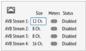
- Rotate the encoder to configure a new stream size and confirm by pressing the encoder again.
To change the amount of channels in the incoming AVB stream with the web remote:
- Connect the device by USB or network cable and open the web remote.
- Click one of the AVB ports in the routing view. The port opens.
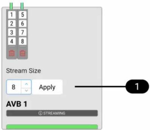
- Adjust the stream size to 4, 8, 12 or 16 channels and click 'Apply'.

Changing a stream size briefly interrupts all incoming and outgoing AVB streams.
10. OUTPUT Section
The output section represents the internal routing matrix and state of the outputs. Routing is performed by selecting an output and assigning any input to it. When a routing is active, its input is automatically monitored for lock and sync in the input section. For AVB stream outputs, their states are additionally monitored in the output section.
Example:
In the OUTPUT section, MADI Optical 1-12 is chosen as source for AVB Stream 2. The M-32 AD Pro is clock master, but the incoming MADI signal is not correctly synchronized. This causes a warning in the INPUT section. If MADI Optical is not routed to any output, an invalid or missing signal does not cause a warning.

Use the web remote to find out quickly which outputs are receiving a specific input signal. The web remote provides a thorough representation of all active routing connections at a glance.
Device Output Section
The device allows full inspection and configuration of outgoing signals including routing in four channel blocks.
Web Remote Output Section
The web remote integrates the output ports with a routing interface.
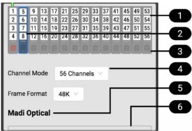
1 Block of four channels
2 Active block
3 Delete Routing
4 Port Settings
5 Port Label
6 Indicator
10.1. MADI Outputs
The MADI outputs of the M-32 AD Pro are always active. If no routing is configured, an empty stream is sent that can be used for clocking. This state is represented with a light-green Status Indicator.
10.1.1. Setting the Output Channel Format and Frame Pattern
Depending on the requirements of the receiver, it is possible to change the channel format and frame pattern of the outgoing MADI streams.
To change the channel format of both MADI outputs on the device:
- Go to one of the MADI tabs in the OUTPUT section.
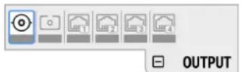
- Toggle the switch to 56Ch or 64Ch to adjust number of output channels.
To change the channel format of both MADI outputs using the web remote:
- Open either MADI output port in the routing view.
- Select the channel mode from the corresponding menu.

56Ch and 64Ch format corresponds to 28/32 channels at double speed, and to 14/16 channels at quad speed.
To change the frame pattern of both MADI outputs on the device:
- Go to one of the MADI tabs in the OUTPUT section.
- Toggle the switch for 96k to use the 96k frame at 88.2 kHz and 96 kHz. .To change the frame pattern of both MADI outputs using the web remote:
- Open either MADI output port in the routing view.
- Select the frame format from the corresponding menu.

96k frame setting is only used at sample rates 88.2 kHz and 96 kHz and is otherwise ignored.

It is not possible to select separate settings for each MADI port. Both ports will be affected regardless which output tab is used to change the setting.
10.1.2. Routing Signals to the MADI Outputs
The M-32 AD Pro features two independent MADI outputs that can stream audio signals. In order to send a signal, a routing is required.

A routing immediately activates input monitoring for the corresponding input and raises a warning in the input state if the signal is not available.
To create a routing to a MADI output on the device:
- Open the OUTPUT section.
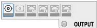
- Rotate the encoder to highlight the coaxial or optical MADI icon.
"Route Signals to MADI Coaxial/Optical Output" text will be shown on the display. - Press the encoder to open the routing. The cursor will highlight the first available channel block.
- Either rotate the encoder to select the next available channel block or press it to start assigning the source signal.
- Again, rotate the encoder to select the source for the selected output.
Choosing "unrouted" deletes an existing routing, and "cancel" aborts the routing and keeps the previous routing.

At single speed MADI, a consecutive routing of the first channels 1-32 and following channels 33-64 can be created in one step. By continuing to rotate the encoder on the output channel block field, those two ranges are followed by a finer granularity of four channels. Those are then displayed as "Channel 1-4", "Channel 5-8", etc.
To create a routing to a MADI output on the web remote:
- Click the MADI coaxial or MADI optical output port.
- Select and click a block of four channels by clicking it. The channels will be highlighted in blue.
- Open any input port and click a block of four channels. A routing is created and displayed with a connection line.
10.1.3. MADI Daisy Chains
MADI is a uni-directional protocol with a fixed number of channels. When more than two MADI devices are connected, a serial connection is required. This is also referred to as a "daisy chain". The output of the first device is connected to the input of the second device, the output of the second device to the input of third device, and so on, until the signal is plugged into the input of the first device.
It is important to understand that each device must be programmed to pass on audio from its MADI input to the MADI output. Otherwise, the last device would only receive the channels of one device.

While many RME devices pass on MADI signals automatically, the M-32 AD Pro must be explicitly configured to do so.
In order to pass on signals, configure the output routing of the required output port to pass on the signal from the MADI input port.

The latency of the MADI I/O is four samples.
10.1.4. MADI Port Mirroring
A redundant MADI connection protects from loss of audio in case of a single cable failure. To achieve redundancy, the receiver must support MADI redundancy. The sender must send two identical MADI signals on two outputs, usually the BNC coaxial and SC optical ports.
The M-32 AD Pro features independent routing for both MADI output ports. For this reason, a "mirroring" of the signal must be manually created. In order to do this, the routing of the two MADI outputs should be configured to contain the same routing.

The receiving device usually ignores the audio contents of the two MADI signals. Therefore, the redundancy may appear to be set up even though the M-32 AD Pro sends different audio signals on both ports.
10.2. AVB Output Streams
The AVB streams leaving the M-32 AD Pro are described as "output streams". In this case, the device acts as a talker. The talker defines the presentation time and therefore the latency across the network. This is set per default to 2 ms.
The output streams of the M-32 AD Pro are by default empty, containing a clock signal but no audio signal. To send audio with AVB, a routing must be created for each outgoing stream.
To establish a connection between a talker and a listener, an AVDECC controller is required. The M-32 AD Pro does not include an AVDECC controller.
Outgoing AVB streams are monitored by the device as follows:
| Description Indicator Possible solution | ||
| Disabled grey Create connection | with AVDECC | controller |
| Streaming/Transmitting green | ||
| SR mismatch red Verify that the sample rates of | talker and listener are identical | |
| Waiting yellow ... Wait for listener to be ready | ||
| Listener Fail red Verify proper listener | configuration | |
| No Bandwidth red Use faster network speed (1 | GBit/s instead of 100 MBit/s) | |
| Domain Boundary red Reconnect all devices and | reboot switch | |
| Internal Error red Reboot device | ||
10.2.1. Change AVB Output Stream Size
Each of the four AVB streams can have a size of 4, 8, 12 or 16 channels.
To change the amount of channels in the outgoing AVB stream on the device:
- Open one of the four AVB tabs in the OUTPUT section.
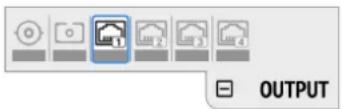
- Move the cursor to highlight the current AVB Stream Size and press the encoder.
- Rotate the encoder to configure a new stream size and confirm by pressing the encoder again.
To change the amount of channels of the outgoing AVB stream:
- Connect to the device remotely (see: Section 8.5.1, "Finding the Device on a Network").
RME M-32 AD Pro User's Guide
- Open an AVB port in the routing area and use the up and down arrows to adjust the stream size
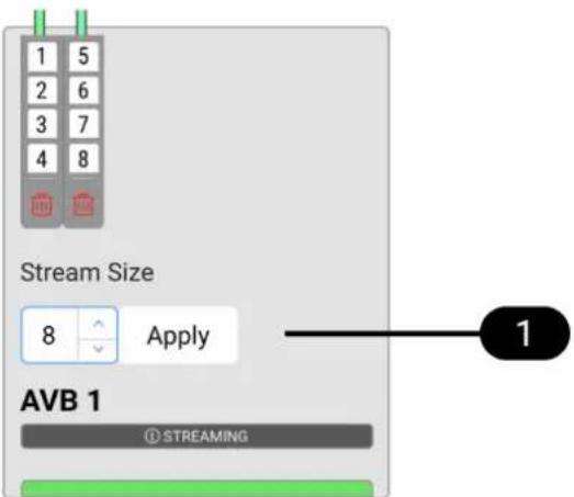
- Click Apply.

Changing a stream size briefly interrupts all incoming and outgoing AVB streams.
11. CLOCK Section
The CLOCK section is used to inspect and configure the clock source and sample rate of the M-32 AD Pro.
Web remote
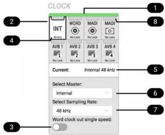
1 Status Indicator
2 Selected Master (frame)
3 Word Clock Output Single Speed Setting
4 Current Master (white)
5 Current Master and Sample Rate
6 Master Selection Dropdown
7 Sample Rate Dropdown
8 Status Indicator
11.1. Clock status
The clock of all digital inputs is continuously monitored with SyncCheck™ and shown in the CLOCK section. A warning occurs when the chosen clock master fails. A caution is displayed when a routed signal is out of sync. A caution notification is displayed when a signal is present, but not in sync and not routed. A good notification is displayed when a signal is present and in sync, but not routed or chosen as clock master. A confirmation is shown when the signal is present and either chosen as master or routed and in sync.

On the standby screen, the two possible notifications are not shown. Those signals are not relevant to the current device state.
11.2. Master Clock
In its the default state, the M-32 AD Pro uses an internal clock signal (master). This means that any connected device must synchronize to it (slave).
Alternatively, one of the digital inputs (word clock, MADI optical, MADI coaxial, and each of the four AVB
streams) can be chosen as clock reference. This activates SteadyClock™ FS, a technology that extracts a low jitter clock signal from the incoming signal.
Intelligent Clock Control (ICC) automatically changes the clock source when the chosen master clock fails. Using the feedback of SyncCheck™, the M-32 AD Pro will change to another source signal that is in sync, maintaining the slave mode and current sample rate. If no other source is available, the device will fall back to its internal clock until the chosen master has recovered. Due to the excellent performance of RME's clock technology, disconnection and re-connection of a master clock is likely to be performed without losing a sample in the outgoing audio signal.

ICC switches the clock source between word clock, MADI optical, MADI coaxial, and internal, seamlessly, when the MADI optical, coaxial or word clock inputs fail and the other port is locked - or to internal. ICC will not fall back to an AVB sync source and also will not affect a chosen AVB master clock.
11.2.1. Selecting a Master Clock
To configure the clock master on the device:
- Enter the CLOCK section. The cursor highlights the currently selected clock.
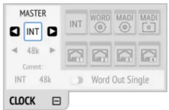
- Push the encoder. Two blue arrows are shown to indicate that the encoder can now be used to change the current setting.
- Rotate the encoder until the preferred clock source is shown.
- Push the encoder again to activate the setting.
To configure the clock master on the web remote:
- Locate the CLOCK section.
- Use the Master: dropdown menu to choose a clock source. The new clock source is applied immediately.
11.3. Sample Rates Overview
The M-32 AD Pro supports the following sample rates:
Supported sample rates
| Single speed 32 kHz, 44.1 kHz, 48 kHz | |
| Double speed 88.2 kHz, 96 kHz | |
| Quad speed 176.4 kHz, 192 kHz |
If the device is clock master, these rates always correspond to the actual sample rate used.
11.3.1. Slave Mode
When the device is slave, certain deviations are automatically accepted to avoid interruption of the outgoing audio signal when the sample rate changes. This is called Intelligent Clock Control (ICC). It also handles deriving a sample rate of double or quad speed based on an incoming rate.
Intelligent Clock Control (ICC)
| Input Clock at input Selected Sample Rate Resulting Sample Rate | |
| MADI 44.1 44.1 44.1 | |
| MADI 44.1 48 44.1 with warning | |
| MADI 44.1 88.2 88.2 | |
| MADI 44.1 96 88.2 with warning | |
| MADI 44.1 176.4 176.4 | |
| MADI 44.1 192 176.4 with warning | |
| MADI 48 44.1 48 with warning | |
| MADI 48 48 48 | |
| MADI 48 88.2 96 with warning | |
| MADI 48 96 96 | |
| MADI 48 176.4 192 with warning | |
| MADI 48 192 192 | |
| MADI 96k 88.2 44.1 warning (no sync) | |
| MADI 96k 88.2 48 warning (no sync) | |
| MADI 96k 88.2 88.2 88.2 | |
| MADI 96k 88.2 96 88.2 with warning | |
| MADI 96k 88.2 176.4 warning (no sync) | |
| MADI 96k 88.2 192 warning (no sync) | |
| MADI 96k 96 44.1 warning (no sync) | |
| MADI 96k 96 48 warning (no sync) | |
| MADI 96k 96 88.2 96 with warning | |
| MADI 96k 96 96 96 | |
| MADI 96k 96 176.4 warning (no sync) | |
| MADI 96k 96 192 warning (no sync) | |
| Word Clock 44.1 44.1 44.1 | |
| Word Clock 44.1 48 44.1 (with warning) | |
| Word Clock 44.1, 88.2 88.2 88.2 | |
| Word Clock 44.1, 88.2 96 88.2 with warning |
RME M-32 AD Pro User's Guide
| Word Clock 44.1, 88.2, 176.4 176.4 176.4 | ||
| Word Clock 44.1, 88.2, 176.4 192 176.4 with warning | ||
| Word Clock 48 44.1 48 with warning | ||
| Word Clock 48 48 48 | ||
| Word Clock 48, 96 88.2 96 with warning | ||
| Word Clock 48, 96 96 96 | ||
| Word Clock 48, 96, 192 176.4 192 with warning | ||
| Word Clock 48, 96, 192 192 192 |
There is no ICC mechanism necessary for AVB; the device will always use the exact clock from the corresponding AVB stream.

It is not recommended to sync devices with a higher sample rate than the current sample rate, because two devices could choose different edges of the incoming clock signal.

ICC does not affect outgoing AVB streams. Outgoing AVB streams will always correspond to the exact sample rate set in the CLOCK section. When the word clock or MADI master changes from 96kHz to 88.2 kHz, and the internal clock is set to 48kHz, the AVB streams will be offline.
11.3.2. Number of Channels
The supported number of channels per port or stream at different sample rates is shown in the following table.
Supported number of audio channels per stream/port and direction at different sample rates
| 32 kHz 44.1 | kHz 48 kHz | 88.2 kHz 96 kHz | 176.4 kHz | 192 kHz | |||
| MADI 56 Ch | 56 56 56 28 | 28 14 14 | |||||
| MADI 64 Ch | 64 64 64 32 | 32 16 16 | |||||
| MADI 56 Ch + 96k | --- --- --- 28 28 --- --- | ||||||
| MADI 64 Ch + 96k | --- --- --- 32 32 --- --- | ||||||
| AVB 4 Ch stream | --- 4 4 4 4 4 4 | ||||||
| AVB 8 Ch stream | --- 8 8 8 8 8 8 | ||||||
| AVB 12 Ch stream | --- 12 12 12 12 12 12 | ||||||
| AVB 16 Ch stream | --- 16 16 16 16 --- --- | ||||||
i
Since there are two independent MADI ports, the total supported number of channels can be multiplied by two. Since there are four independent AVB streams, the total supported number of channels can be multiplied by four. The analog channel count is always 32 regardless of sample rate. The maximum amount of digital inputs is 192 channels (at 48 kHz, 64 Ch MADI). The maximum amount of digital outputs is 192 channels (at 48 kHz, 64 Ch MADI).
11.3.3. Selecting a Sample Rate
To configure the device sample rate on the device:
- Enter the CLOCK section. The cursor highlights the currently selected clock.
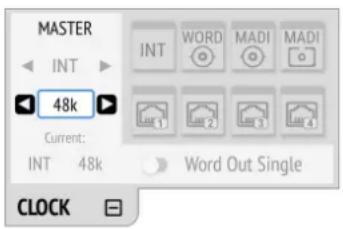
- Rotate the encoder to highlight the current sample rate.
- Push the encoder. Two blue arrows will appear to indicate that the encoder can now be used to change the current setting.
- Rotate the encoder until the preferred sample rate is shown.
- Push the encoder again to activate the setting.
To configure the device sample rate on the web remote:
- Locate the Select sample rate drop down menu in the CLOCK section.
- Select a sample rate from the drop down menu. The new rate is automatically applied.
11.3.4. Effects of Sample Rate Changes on Existing Routing
The M-32 AD Pro saves one routing table per preset, regardless of sample rate. A change of sample rate or MADI frame mode can reduce the number of input and output channels available for routing. This does not alter the routing table. Any existing routing is hidden until another change of sample rate reenables the channels.
Example:
A routing is created at 96 kHz with 32 channels, sending the MADI coaxial Input 1-32 to optical MADI Output 1-32. If the sample rate is now changed to 176.4 kHz and the 56 Ch frame is activated, only the first 14 channels of MADI coaxial input are routed to the optical output. Switching the sample rate to 44.1 or 48 kHz will reveal the previous routing for 32 channels.
11.4. Set Word Clock Output to Single Speed
At sample rates > 48 kHz, it may be necessary to synchronize two devices with a fraction of the actual sample rate:
| Sample Rate Word Clock Full Speed | peed (default) Word Clock Single Speed | speed (option) |
| 88.2 kHz 88.2 kHz 44.1 kHz |
RME M-32 AD Pro User's Guide
| Sample Rate Word Clock Full Speed (default) Word Clock Single Speed (option) | ||
| 96 kHz 96 kHz 48 kHz | ||
| 176.4 kHz 176.4 kHz 44.1 kHz | ||
| 192 kHz 192 kHz 48 kHz | ||
To set the Word Clock output to single speed on the device:
- Open the CLOCK section.
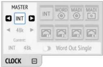
- Move the cursor onto the toggle switch Word Out Single and push the encoder to change the value.
To set the Word Clock output to single speed on the web remote:
- Locate the CLOCK section.
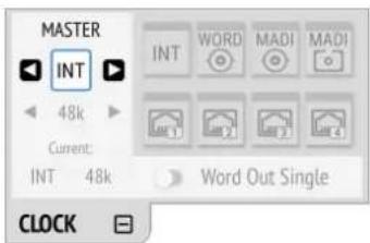
- Move the cursor onto the Word Out Single switch and push the encoder to change the value.
12. Annex
Trademarks and Copyright
All trademarks, registered or otherwise, are the property of their respective owners.
RME is a registered trademark of RME Intelligent Audio Solutions.
SyncCheck, SteadyClock, ICC, Intelligent Clock Control and Digiface are trademarks of RME Intelligent Audio Solutions.
Microsoft, Windows, Windows 7/8/10 are registered trademarks of Microsoft Corp.
Apple and macOS are registered trademarks of Apple Inc.
Schurter and V-Lock are registered trademarks of Schurter Holding AG.
Copyright © 2018 m2lab Ltd.
This manual is licensed under a Creative Commons Attribution-NonCommercial-NoDerivatives 4.0 International License.
12.1. MIDI Implementation Chart
12.1.1. Basic SysEx format
Value Name
F0h SysEx header
00h 20h 0Dh MIDITEMP manufacturer ID
32h Model ID (M-Series)
00h..7Eh, Bank number / device ID (7Fh = 7Fh broadcast, all IDs)
mm Message type
nn Parameter number (see table 1)
oo Data byte
F7h EOX
Bank Number / Device ID The lower nibble refers to the device ID (0..7), the higher nibble refers to the bank number (0..7), e. g. 25h means bank 2, device 5. 7Fh addresses all banks and all devices.
12.1.2. Message Types
Value Name
10h Request value
20h Set value
30h Value response
Request Value
RME M-32 AD Pro User's Guide
Format: F0 00 20 0D 32 (bank no. / dev ID) 10 F7 This string triggers a complete dump of all value response data bytes including the level meter data.
Set Value
Sets any number of parameters. nn / oo can be repeated freely.
Value Response
After being triggered by receiving a request value command, device sends a string of all value response data bytes. Message type is set to 30h.
12.1.3. Table
| No. No | . | Name Set | Val. | Val. Resp. | Data bytes |
| 00h 0 | settings byte 1 x x hex coded value of byte (see below) | ||||
| 01h 1 | settings byte 2 x x hex coded value of byte (see below) | ||||
| 02h 2 | settings byte 3 x x hex coded value of byte (see below) | ||||
| 03h 3 | info byte 1 x hex coded value of byte (see below) | ||||
| 04h 4 | info byte 2 x hex coded value of byte (see below) | ||||
| 05h 5 | info byte 3 x hex coded value of byte (see below) | ||||
| 06h 6 | info byte 4 x hex coded value of byte (see below) | ||||
| 07h 7 | level ch 01 x (see below) | ||||
| 08h 8 | level ch 02 x (see below) | ||||
| 09h 9 | level ch 03 x (see below) | ||||
| 0Ah 10 | level ch 04 x (see below) | ||||
| 0Bh 11 | level ch 05 x (see below) | ||||
| 0Ch 12 | level ch 06 x (see below) | ||||
| 0Dh 13 | level ch 07 x (see below) | ||||
| 0Eh 14 | level ch 08 x (see below) | ||||
| 0Fh 15 | level ch 09 x (see below) | ||||
| 10h 16 | level ch 10 x (see below) | ||||
| 11h 17 | level ch 11 x (see below) | ||||
| 12h 18 | level ch 12 x (see below) | ||||
| 13h 19 | level ch 13 x (see below) | ||||
| 14h 20 | level ch 14 x (see below) | ||||
| 15h 21 | level ch 15 x (see below) | ||||
| 16h 22 | level ch 16 x (see below) | ||||
| 17h 23 | level ch 17 x (see below) | ||||
RME M-32 AD Pro User's Guide
| No. No | . | Name Set | Val. | Val. Resp. | Data bytes |
| 18h 24 | level | ch 18 x (see below) | |||
| 19h 25 | level | ch 19 x (see below) | |||
| 1Ah 26 | level | ch 20 x (see below) | |||
| 1Bh 27 | level | ch 21 x (see below) | |||
| 1Ch 28 | level | ch 22 x (see below) | |||
| 1Dh 29 | level | ch 23 x (see below) | |||
| 1Eh 30 | level | ch 24 x (see below) | |||
| 1Fh 31 | level | ch 25 x (see below) | |||
| 20h 32 | level | ch 26 x (see below) | |||
| 21h 33 | level | ch 27 x (see below) | |||
| 22h 34 | level | ch 28 x (see below) | |||
| 23h 35 | level | ch 29 x (see below) | |||
| 24h 36 | level | ch 30 x (see below) | |||
| 25h 37 | level | ch 31 x (see below) | |||
| 26h 38 | level | ch 32 x (see below) | |||
| 27h 39 | fan control x (see below) | ||||
| 28h 40 | temperature x (see below) | ||||
| 29h 41 | (reserved) x | ||||
| 30h 48 | (reserved) x | ||||
| 31h 49 | set device id x (response displays in header) | ||||
| 00h 0 | settings byte 1 MSB / 7 | 0 | ||
| 6 | ||||
| 5 | ||||
| 4 | ||||
| LSB / 0 | ||||
| 01h 1 | settings byte 2 MSB / 7 | 0 | ||
| 6 | MSB / 2 | |||
| 5 | 1 | |||
| 4 | LSB / 0 | |||
| 3 |
RME M-32 AD Pro User's Guide
| 00h 0 | settings byte 1 MSB / 7 | 0 | |||
| 2 | follow | clock: 0 = off, 1 = | on | ||
| 1 | MSB / | 1 clock state: 0 = | single speed, 1 = ds, 2 = qs | ||
| LSB / 0 | LSB / 0 clock state | ||||
| 02h 2 | settings byte 3 MSB / 7 | 0 | |||
| 6 | MSB / | 1 analog level: 0 = | +13, 1 = +1 | 9, 2 = +24 | |
| 5 | LSB / 0 | analog level | |||
| 3 | MSB / | 1 Peak Hold: 0 = off, 1 = auto reset, | |||
| 2 | LSB / 0 | Peak Hold: 2 = manual, 3 = reset (tx only) | |||
| 1 | 0 | ||||
| 03h 3 | info byte 1 | MSB / 7 0 | ||
| 5 | MADI lock | |||
| 4 | MADI sync | |||
| 3 | MADI input 96k frame | |||
| 1 | model subtype: 1 = M-32 | |||
| LSB / 0 | model subtype: 0 = AD, 1 = DA | |||
| 04h 4 | info byte 2 | MSB / 7 0 | ||
| 6 | WCK | ock | ||
| 5 | WCK | Input 192k | ||
| 4 | WCK | Input 96k | ||
| 3 | 0 | |||
| 2 | 0 | |||
| 1 | n.u. | |||
| LSB / 0 | n.u. | |||
| 7.. | 38 | level meter data | MSB / 7 | 0 | ||
| 2 | MSB | / 2 | level 000..101 (AD) | |||
| 1 | 1 | Level | ||||
RME M-32 AD Pro User's Guide
| 7.. | 38 | level meter data MSB | / 7 | 0 | |
| LSB / | 0 | LSB / 0 | Level | ||
| level steps: AD 000 -oo | ||||
| 001 -42 | ||||
| 010 -18 | ||||
| 011 -9 | ||||
| 100 -3 | ||||
| 101 Over |
12.2. Declarations of conformity
12.2.1. CE Compliance
This device has been tested and found to comply with the limits of the European Council Directive on the approximation of the laws of the member states relating to electromagnetic compatibility according to RL2014/30/EU, and European Low Voltage Directive RL2014/35/EU.
12.2.2. FCC Compliance
This device complies with Part 15 of the FCC Rules. Operation is subject to the following two conditions: (1) this device may not cause harmful interference, and (2) this device must accept any interference received, including interference that may cause undesired operation.
WARNING: Changes or modifications to this unit not expressly approved by the party responsible for compliance could void the user's authority to operate the equipment.
NOTE: This equipment has been tested and found to comply with the limits for a Class B digital device, pursuant to Part 15 of the FCC Rules. These limits are designed to provide reasonable protection against harmful interference in a residential installation. This equipment generates, uses and can radiate radio frequency energy and, if not installed and used in accordance with the instructions, may cause harmful interference to radio communications. However, there is no guarantee that interference will not occur in a particular installation. If this equipment does cause harmful interference to radio or television reception, which can be determined by turning the equipment off and on, the user is encouraged to try to correct the interference by one or more of the following measures:
- Reorient or relocate the receiving antenna.
- Increase the separation between the equipment and receiver.
- Connect the equipment into an outlet on a circuit different from that to which the receiver is connected.
- Consult the dealer or an experienced radio/TV technician for help.
Shielded cables must be used with this unit to ensure compliance with the Class B FCC limits.
Responsible Party in USA: Synthax United States, 6600 NW 16th Street, Suite 10, Ft Lauderdale, FL 33313 T.:754.206.4220
Trade Name: RME, Model Number: M-32 AD Pro
12.2.3. Note on Disposal
According to the guide line RL2002/96/EG (WEEE – Directive on Waste Electrical and Electronic Equipment), valid for all european countries, this product has to be recycled at the end of its lifetime. In case a disposal of electronic waste is not possible, the recycling can also be done by Scheck Audio GmbH, the manufacturer of this device.
For this the device has to be sent free to the door to:
Scheck Audio GmbH, 3. Industriestr. 5, 68804 Altlussheim, Germany.
Shipments not prepaid will be rejected and returned on the original sender's costs.
- Table of Contents
- Safety Precautions
- Introduction
- Firmware Update
- RME M-32 AD Pro User's Guide
- Use of the Display and Encoder
- Sections
- Tabs
- Status Indicator Color Chart
- Hardware
- Hardware Specifications
- RME M-32 AD Pro
- Package Contents
- Power On
- Standby Switch
- Possible actions:
- Ring Illumination
- No illumination
- Permanent red illumination
- Permanent white illumination
- Alternating red/white illumination
- Channel Labels with Integrated Metering
- Meter Backlight Color and Intensity Reference
- Replacing the Channel Labels
- Control Section
- Power Supplies
- Lockable IEC plugs
- Analog Line Input Connectors
- Analog Line Levels
- AD Converter Specifications
- Line In 1-32:
- MADI Connectors
- Network Connection
- MIDI Connector
- Word Clock
- Possible States:
- USB 2.0 Type B Jack
- Mounting the Rack Adapter Brackets
- Accessories
- Part Number Description
- Manufacturer Part Number Description
- AVB Connectivity
- Network Control
- Audio Streaming
- Identifying a Device Remotely
- Changing the Device Name
- AVB Stream Size
- AVB Network Latency
- Adjusting the network latency
- Quick Start (MADI)
- Further steps to enhance your start:
- State
- Input
- Output
- Warranty and Support
- Warranty
- Support
- Support Contacts
- Europe
- Asia/Australia
- Americas
- Global
- STATE Section
- Power State
- Representation of the power states on the device
- Representation of the power state on the web remote
- Notification of Single Power Failure
- Power loss at PSU 2
- Presets
- Settings that are not saved in a Preset
- Saving Presets
- Loading Presets
- To load a preset on the device:
- Press the Load Button 4
- Loading Factory Default Settings
- Device Lock
- Locking the Device
- Unlocking the Device
- Front Panel Illumination
- Dark Mode
- Changing the Meters to Peak or RMS Mode
- Persistent Clipping Notifications
- Metering of Digital Input Signals
- Remote Control Overview
- Finding the Device on a Network
- USB
- Ethernet
- Connecting to the Remote Interface without IP address
- Web Remote
- Web Remote Overview
- Device Information
- INPUT Section
- Analog Inputs
- Adjusting the Input Line Level
- ADC Converter Mute
- MADI Input
- MADI at High Sample Rates
- Double speed (88.2 kHz, 96 kHz)
- 96k frame
- S/MUX 2
- Quad Speed (176.4 kHz, 196 kHz)
- Connecting Two Identical MADI Signals for Redundancy
- To create MADI redundancy:
- AVB Input Streams
- Change AVB Input Stream Size
- OUTPUT Section
- Example:
- Device Output Section
- Web Remote Output Section
- MADI Outputs
- Setting the Output Channel Format and Frame Pattern
- Routing Signals to the MADI Outputs
- MADI Daisy Chains
- MADI Port Mirroring
- AVB Output Streams
- Change AVB Output Stream Size
- CLOCK Section
- Web remote
- Clock status
- Master Clock
- Selecting a Master Clock
- Sample Rates Overview
- Slave Mode
- Number of Channels
- i
- Selecting a Sample Rate
- Effects of Sample Rate Changes on Existing Routing
- Set Word Clock Output to Single Speed
- Annex
- Trademarks and Copyright
- MIDI Implementation Chart
- Basic SysEx format
- Value Name
- Message Types
- Declarations of conformity
- CE Compliance
- FCC Compliance
- Note on Disposal
Brand : RME
Model : M-32 AD Pro
Category : Audio/video converter