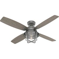
Port Royale 50390 - Household Fan HUNTER - Free user manual and instructions
Find the device manual for free Port Royale 50390 HUNTER in PDF.


| Product Type | Ceiling Fan |
| Brand | Hunter |
| Model | Port Royale 50390 |
| Finish | Brushed Nickel |
| Blade Span | 52 inches (132 cm) |
| Blade Pitch | 12 degrees |
| Number of Blades | 5 |
| Motor Type | Reversible, 3-speed |
| Light Kit | Included, 2 x 40W candelabra bulbs (not included) |
| Control | Pull chain; compatible with optional remote control |
| Airflow | 5,000 CFM (high speed) |
| Noise Level | 22 dB (low speed) |
| Weight | 14.5 lbs (6.6 kg) |
| Height | 12 inches (30.5 cm) |
| Voltage | 120V AC, 60Hz |
| Current | 0.65 A |
| Power Consumption | 78 Watts (high speed) |
| Usage | Indoor |
| Mounting | Standard or angled ceiling up to 30° |
| Warranty | Limited Lifetime Motor Warranty |
| Cleaning | Wipe with soft dry cloth; no water or detergents |
| Spare Parts Available | Blades, light kits, pull chains, switches |
| Certifications | ETL Listed, UL |
Frequently Asked Questions - Port Royale 50390 HUNTER
User questions about Port Royale 50390 HUNTER
0 question about this device. Answer the ones you know or ask your own.
Ask a new question about this device
Download the instructions for your Household Fan in PDF format for free! Find your manual Port Royale 50390 - HUNTER and take your electronic device back in hand. On this page are published all the documents necessary for the use of your device. Port Royale 50390 by HUNTER.
USER MANUAL Port Royale 50390 HUNTER
natural_image
Black-and-white photo of a double-decker air conditioner with four blades and a lampshade, placed on a bed with white cushions (no text or symbols visible)Port Royale
Installation Manual
Model: 50390 Matte Silver
50391 Natural Iron
Fan weight ±2 lbs: 23.6 lbs (10.7 kg)
The ceiling fan you purchased will provide comfort and performance in your home or office for many years. This instruction manual contains complete instructions for installing and operating your fan. We are proud of our work and appreciate the opportunity to supply you with the best ceiling fan available anywhere in the world.
We are here to help!
This Instruction Manual is designed to make installation as simple as possible. While working through this Instruction Manual, keep your smartphone or tablet nearby. We have added video links to help you through the more technical sections. If you are unfamiliar or uncomfortable with wiring, contact a qualified electrician. We also provide telephone support at 1.888.830.1326 or visit us at HunterFan.com.

READ and SAVE These Instructions
WARNING


Warning
w.1 - To reduce the risk of fire, electrical shock, or personal injury, mount fan directly from building structure and/or an outlet box marked acceptable for fan support of 70 lbs (31.8 kg) and use the mounting screws provided with the outlet box.
w.2 - To avoid possible electrical shock, before installing or servicing your fan, disconnect the power by turning off the circuit breakers to the outlet box and associated wall switch location. If you cannot lock the circuit breakers in the off position, securely fasten a prominent warning device, such as a tag, to the service panel.
w.3 – To reduce the risk of electric shock, this fan must be installed with an isolating wall control/switch.
w.4 - To reduce the risk of personal injury, do not bend the blade brackets when installing the blade brackets, balancing the blades, or cleaning the fan. Do not insert foreign objects in between rotating fan blades.
Caution
c.1 - All wiring must be in accordance with national and local electrical codes ANSI/NFPA 70. If you are unfamiliar with wiring, use a qualified electrician.
c.2 - Use only Hunter replacement parts.
This equipment has been tested and found to comply with the limits for a Class B digital device, pursuant to part 15 of the FCC Rules. These limits are designed to provide reasonable protection against harmful interference in a residential installation. This equipment generates, uses and can radiate radio frequency energy and if not installed and used in accordance with the instructions may cause harmful interference to radio communications.
However, there is no guarantee that interference will not occur in a particular installation. If this equipment does cause harmful interference to radio or television reception, which can be determined by turning the equipment off and on, the user is encouraged to try to correct the interference by one or more of the following measures:
- Reorient or relocate the receiving antenna.
- Increase the separation between the equipment and receiver.
- Connect the equipment into an outlet on a circuit different from that to which the receiver is connected.
- Consult the dealer or an experienced radio/TV technician for help.
Caution: modifications not approved by the party responsible for compliance could void user's authority to operate the equipment.
This device complies with Part 15 of the FCC Rules. Operation is subject to the following two conditions: (1) This device may not cause harmful interference, and (2) this device must accept any interference received, including interference that may cause undesired operation.
This product conforms to UL Standard 507.

Intertek
Here are the tools you'll need to complete your installation:
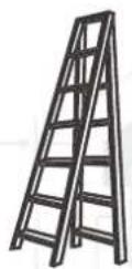
Ladder

Screwdriver
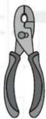
Pliers

Wire Strippers
OPTIONAL
If mounting to a support structure, you will also need these tools.

natural_image
Illustration of a handheld electric drill bit (no text or symbols)
9/64" Drill BitDrill
© 2019 Hunter Fan Company
7130 Goodlett Farms Pkwy, Suite 400
MemphisTN38016
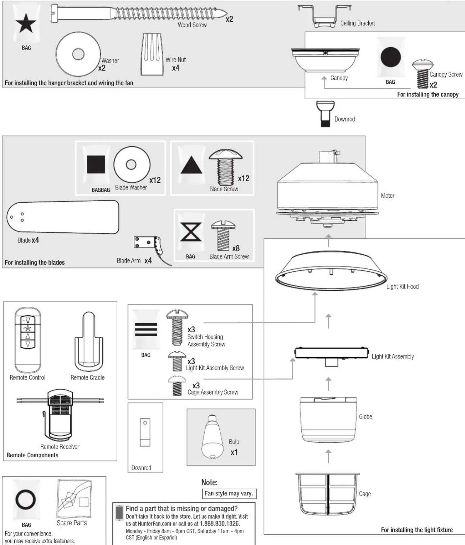
Here is what comes in your box:
We recommend that you pull everything out of the box and lay it out. We have grouped the drawn components below with the hardware you'll need for those parts. The screws below are drawn to scale to make it easier to identify what piece of hardware is needed to install each component.
Hunter Pro Tip:


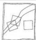
Choosing the Right Installation Location
You probably bought this fan with a location in mind. Let's check below to make sure it is a good fit.
Check the room dimensions: Check the outlet box:


natural_image
Simple line drawing of a mechanical component with a curved pipe and base, set against a wooden background (no text or symbols)You must be able to secure the fan to building structure or fan-rated outlet box.
Checking the Ceiling Angle:
Standard Mounting

If you have a flat ceiling:
Hang your fan by a standard downrod. Some fans come with a shorter downrod for a Low Profile installation.

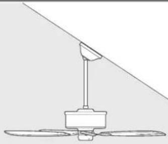
If you have an angled or vaulted ceiling:
- You will need a longer downrod. (Sold separately at HunterFan.com)
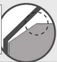
- If your ceiling angle is greater than 34^ , you will also need an Angled Mounting Kit. (Sold separately at HunterFan.com)
Angled Mounting
A little more information on Angled Mounting:
For optimum performance and appearance, a longer downrod should be used with your Hunter ceiling fan when installing on high or angled ceiling. If your ceiling is angled greater than 34° you will also need an Angled Mounting Kit. Longer downrods and the Angled Mounting Kit are sold separately at HunterFan.com.
Hunter Pro Tip:
Determining if you need an Angled Mounting Kit: Fold on the dotted line. Place against edge against the wall. Slide towards the ceiling. If the guide touches the wall but not the ceiling, you need an angled mounting kit.
natural_image
Line drawing of a three-blade fan with a vertical support and diagonal line above (no text or symbols)


Installing the Ceiling Bracket
You have two options for installation. Pick which one works best for your location. Remove any existing bracket prior to installation. Only use the provided Hunter ceiling bracket that came in your fan's box.
Hunter Pro Tip:
The machine screws are the ones that came with your outlet box.

Do this first!
WARNING

To avoid possible electrical shock, before installing your fan, disconnect the power by turning off the circuit breakers to the outlet box associated with the wall switch location.

Option 2: Wood Screws
Use wood screws and washers (included) when securing to support structure with approved electrical outlet box. Drill 9/64 in pilot holes in support structure to aid in securing ceiling bracket with hardware found in the ★hardware bag.

Installing the Downrod
Follow below if you are using the downrod that came pre-assembled in your box. Need to install a longer or shorter downrod? Check out the guide at the end of this manual.

Hanging the Fan

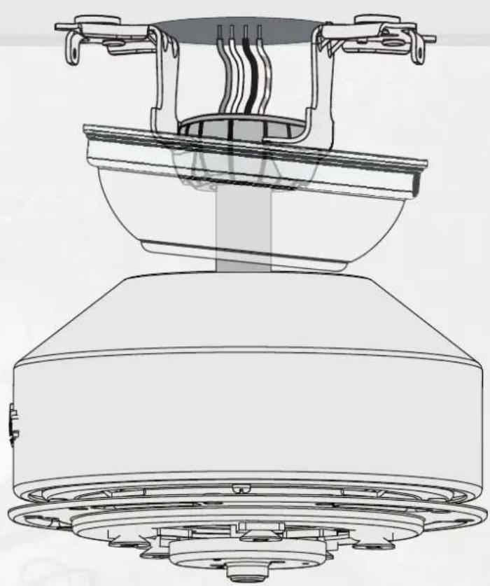
Progress Check:
Your fan should look like this.
natural_image
Technical line drawing of a mechanical component with no visible text or symbolsWiring the Fan
We know wiring is hard. Let's make it easier.
Follow these steps to get your fan wired quickly and safely. Follow the route below that best matches your wall switch setup. If you are unfamiliar with wiring or uncomfortable doing it yourself, please contact a qualified electrician.
Hunter Pro Tip:
Here is how to connect the wires:
Push the bare metal ends of the wires together and slide a wire nut over them. Then, twist the wire nut clockwise until tight.
Give it a gentle pull to make sure none of the wires are loose.

WARNING
The ceiling fan must be grounded. If the ground wire for the installation site is not present, immediately STOP installation and consult a qualified electrician.
WARNING
All wiring must be in accordance with national and local electrical codes ANSI/NFPA 70. If you are unfamiliar with wiring or in doubt, consult a qualified electrician.
Hunter Pro Tip:
Have extra wiring?
Turn the wires upward and push them carefully back through the hanger bracket into the outlet box. Make sure that the wires are still attached to the wire nuts.
Connect the black (ungrounded) wire from the ceiling to the black wire from the receiver.

Installing the Canopy

Installing the Blades:

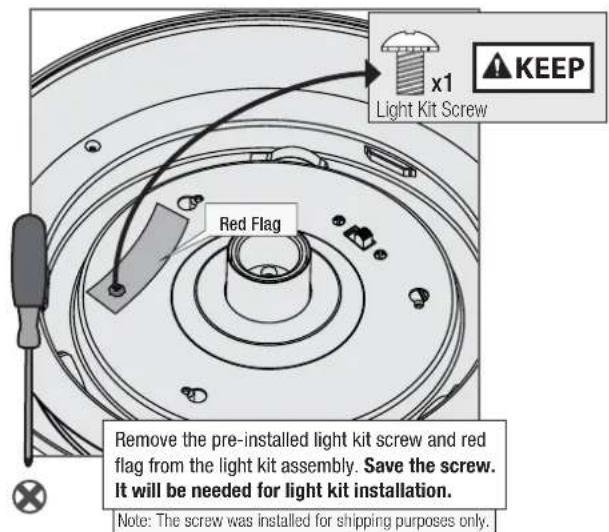
Preparing the Light Fixture
Follow these steps to prepare the light fixture for installation.

Installing the Light Fixture Hood


Installing the Light Fixture

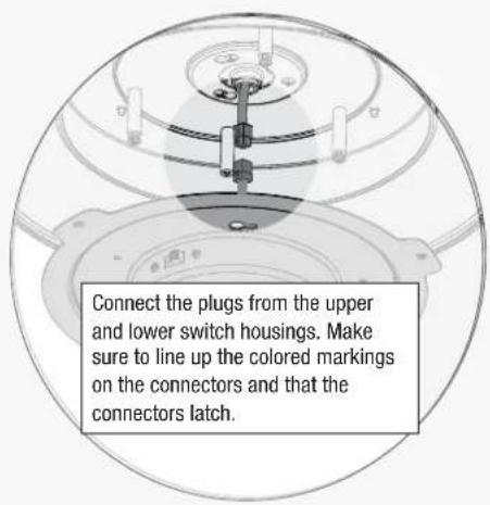
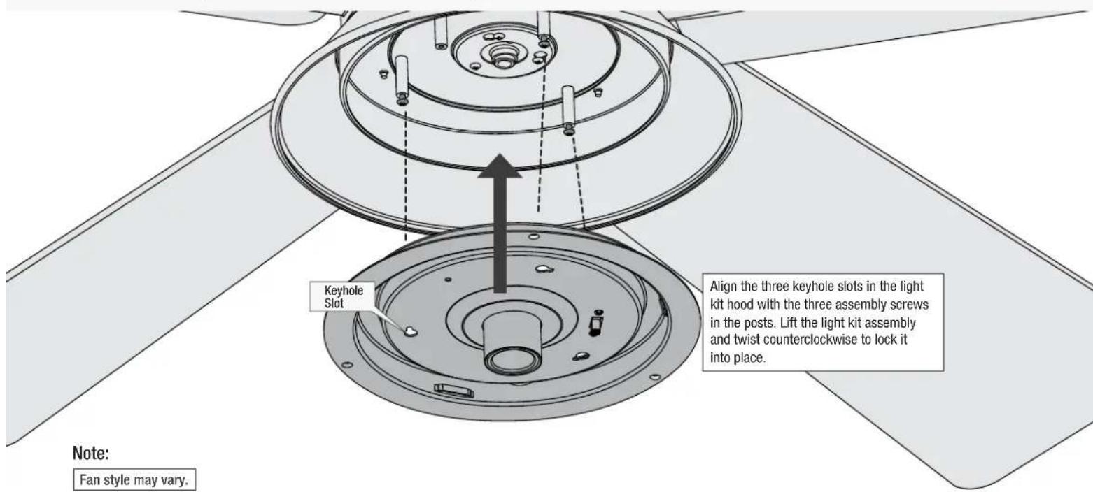
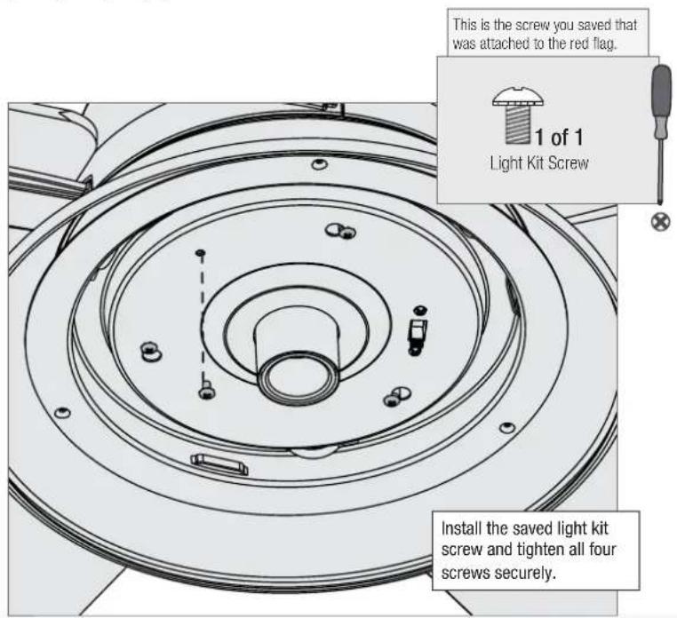

WARNING
FAN FALL HAZARD
Make sure screws are tight to secure the light fixture.

Installing the Glass and Light Fixture Cage

Position the notches in the outer rim of the globe so they line up with the tabs on the light kit assembly. Carefully lift the globe up inside the light kit assembly as far as it will go. Rotate the globe in a clockwise direction until it is held tightly in place by the three tabs.

natural_image
Technical diagram of a ceiling fan assembly with an air vent and internal structure (no text or labels)Lift the cage assembly into place
Note:
Fan style may vary.
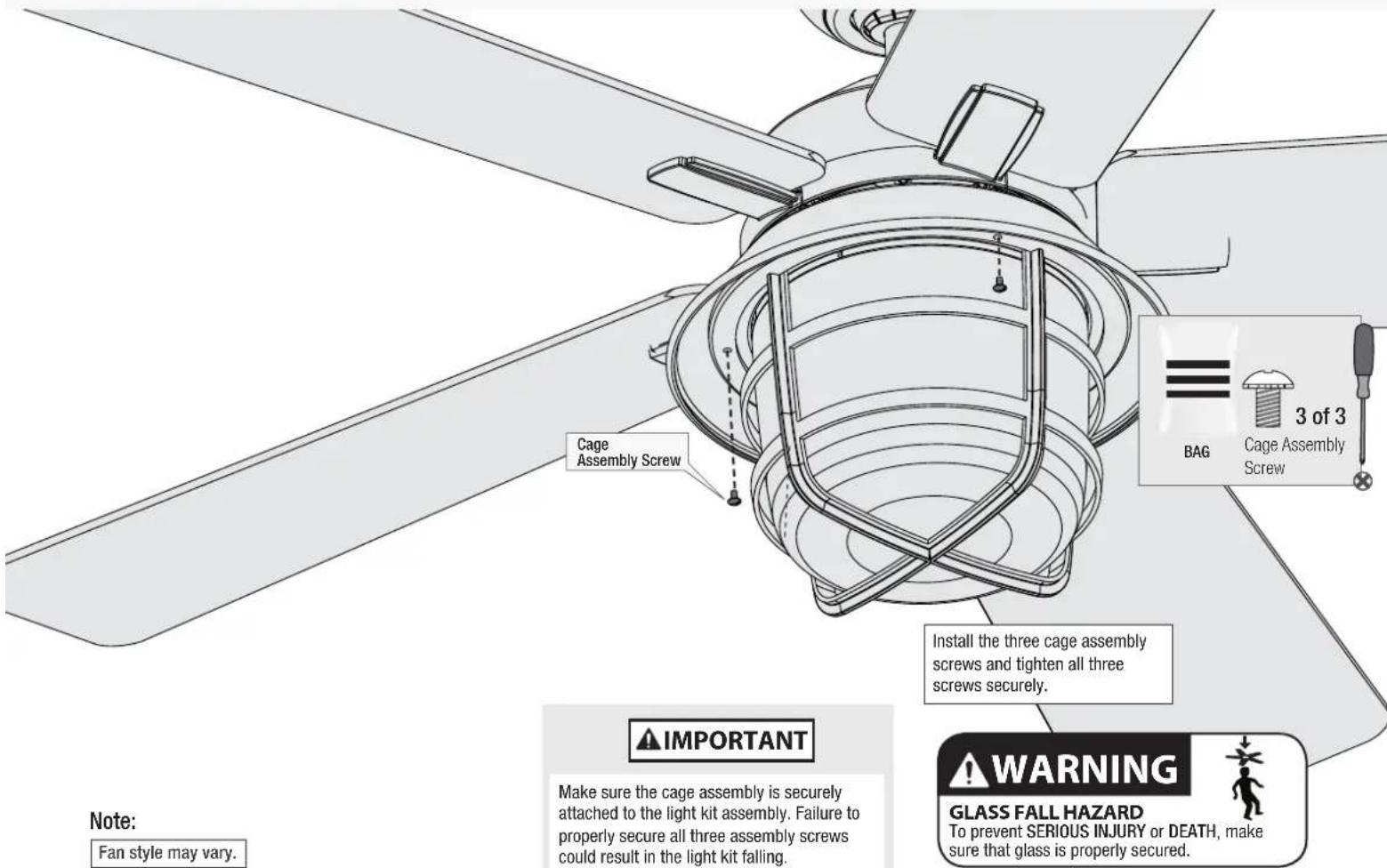
Note:
Fan style may vary.
IMPORTANT
Make sure the cage assembly is securely attached to the light kit assembly. Failure to properly secure all three assembly screws could result in the light kit falling.
WARNING
GLASS FALL HAZARD
To prevent SERIOUS INJURY or DEATH, make sure that glass is properly secured.

Preparing the Remote

For your convenience, a remote function card is packed in with your remote.
To access the battery compartment, remove the the battery door to the transmitter assembly.
Battery Door

natural_image
Pure diagram of a cylindrical container with internal structure and no text or symbolsIMPORTANT
• Always purchase the correct size and grade of battery most suitable for the intended use.
- Replace all batteries of a set at the same time.
- Clean the battery contacts and also those of the device prior to battery installation.
- Ensure the batteries are installed correctly with regard to polarity (+ and -).
- Remove batteries from equipment which is not to be used for an extended period of time.
- Remove used batteries promptly.
Install two AAA batteries, found in the remote control hardware bag, into the transmitter. Clean the battery contacts prior to installing the batteries. Please contact your local battery recycling center for proper battery disposal information.

natural_image
Diagram of a ceiling fan with a control panel and indicator lights, showing no text or symbols.The remote transmitter is already paired to the receiver and ready to use. Dimming mode is off by default.
Note: If your need to pair your remote, turn fan power off and back on at the wall switch. Within 3 minutes, press and hold both the Fan Off button and the High button for 4 seconds to pair the remote. To prevent faulty operation, please ensure all other ceiling fans within range are turned off at the wall switch while pairing.


The Fan On/Off button turns the fan on or off. Adjust the fan speed using the "Fan Speed Up" or "Fan Speed Down" directional buttons.
Quickly press the Light button to turn the lights off and on. Hold the Light button to raise and dim the light level.
NOTICE: DIMMING MODE
To enable dimming, your remote must be set to Dimming Mode. To toggle Dimming Mode on or off, long press the "Fan Speed Up" button and "Fan Speed Down" button.
Installing the Remote Control Cradle
You have two options for installing the remote cradle.
Choose which path works best for you.

flowchart
graph TD
    A["Remove the cradle from the cradle bracket."] --> B["Separate the lining from the back of the adhesive strip on the cradle bracket."]
    B --> C["Press the cradle bracket against the wall and hold firmly for 30 seconds."]
    C --> D["Choose your cradle installation location."]
    D --> E["Slide the cradle onto the mounted bracket."]
Troubleshooting
Fan Doesn't Work
• Make sure power switch is on.
- Push the motor reversing switch firmly left or right to ensure that it is engaged.
- Check the circuit breaker to ensure the power is turned on.
• Make sure the blades spin freely.
- Turn off power from the circuit breaker, then loosen the canopy and check all the connections according to the wiring diagram.
- Check the plug connection in the switch housing.
Excessive Wobbling
- Make sure the blades are properly installed on the blade iron posts.
- Turn the power off, support the fan carefully, and check that the hanger ball is properly seated.
- Use the provided balancing kit and instructions to balance the fan.
Remote Control of Fan is Erratic
• Make sure the battery is installed correctly.
• Install a fresh battery.
Remote Only Works Close to Fan
- Change battery.
Noisy Operation
• Make sure the blades are properly installed.
- Check to see if any of the blades are cracked. If so, replace all of the blades.
Multiple Remote Issues
- If you have multiple remotes or multiple remote-controlled fans installed on the same circuit breaker and you are experiencing interference or faulty operation of your remote controls, please go to www.HunterFan.com/FAQs and click "How do I properly install multiple remote-controlled fans?" for information on how to correct this issue.
Hunter Pro Tip:
Cleaning the Fan
Use soft brushes or cloths to prevent scratching.
Cleaning products may damage the finishes.
Reversing the Fan

Limited Lifetime Warranty
Hunter Fan Company grants this limited warranty to the original purchaser of this Hunter ceiling fan. This document can be found at www.HunterFan.com. Thank you for choosing Hunter!
How Can Warranty Service Be Obtained?
Proof of purchase is required when requesting warranty service. The original purchaser must present a sales receipt or other document that establishes proof of purchase. Hunter, at its sole discretion, may accept a gift receipt. To obtain service, contact Hunter Fan Company online or by phone.
www.HunterFan.com/Support/Contact-Us/1.888.830.1326
Monday - Friday 8am - 6pm CST. Saturday 11am - 4pm CST (English or Español)
Please do not ship your fan or any fan parts to Hunter. Delivery will be refused.
What Does This Warranty Cover?
Motor — Limited Lifetime Warranty
If any part of your ceiling fan motor fails during your ownership of the fan due to a defect in material or workmanship, as determined solely by Hunter, Hunter will provide you with a replacement fan free of charge.* The foregoing limited warranty applies only to the motor itself and does not apply to electronic controls – such as remote control transmitters, remote control receivers, or capacitors – used in conjunction with the motor. Such electronic control items are included in the one-year limited warranty below.
Other — One-Year Limited Warranty
Except as otherwise indicated throughout this warranty, if any part of your Hunter ceiling fan fails at any time within one year of the date of purchase due to a defect in material or workmanship, as determined solely by Hunter, Hunter will provide a replacement part free of charge.*
Light Kits — Warranty May Vary
Light kits are included in the one-year limited warranty. However, you may qualify for additional warranty coverage if your fan includes one of the following:
• LED Light Kits — Three-Year Limited Warranty
If your LED light kit module (not including glass components) or LED bulb fails at any time within three years of the date of purchase due to a defect in material or workmanship, as determined solely by Hunter, Hunter will provide a replacement part free of charge.*
What Does This Warranty NOT Cover?
Labor Excluded. This warranty does not cover any costs or fees associated with the labor (including electrician's fees) required to install, remove, or replace a fan or any fan parts. There is no warranty for light bulbs (except where otherwise noted); remote control batteries; fans purchased or installed outside the United States; fans owned by someone other than the original purchaser; fans for which proof of purchase has not been established; fans purchased from an unauthorized dealer; ordinary wear and tear; minor cosmetic blemishes; refurbished fans; and fans that are damaged due to any of the following: improper installation, misuse, abuse, improper care, failure to follow Hunter instructions, accidental damage caused by the fan owner or related parties, modifications to the fan, improper or incorrectly performed maintenance or repair, improper voltage supply or power surge, use of improper parts or accessories, failure to provide maintenance to the fan, or acts of God (e.g. flood).
ORIGINAL PURCHASER'S SOLE AND EXCLUSIVE REMEDY FOR A CLAIM OF ANY KIND WITH RESPECT TO THIS PRODUCT SHALL BE THE REMEDIES SET FORTH HEREIN.
HUNTER FAN COMPANY IS NOT RESPONSIBLE FOR CONSEQUENTIAL OR INCIDENTAL DAMAGES, DUE TO PRODUCT FAILURE, WHETHER ARISING OUT OF BREACH OF WARRANTY, BREACH OF CONTRACT, OR OTHERWISE. Some States do not allow the exclusion or limitation of incidental or consequential damages, so the above limitation or exclusion may not apply to you.
ANY IMPLIED WARRANTIES OF MERCHANTABILITY OR FITNESS FOR A PARTICULAR PURPOSE APPLICABLE TO THIS PRODUCT ARE LIMITED IN DURATION TO THE PERIOD OF COVERAGE OF THE APPLICABLE LIMITED WARRANTIES SET FORTH ABOVE. Some States do not allow limitations on how long an implied warranty lasts, so the above limitation may not apply to you.
How Does State Law Affect Warranty Coverage?
This warranty gives you specific legal rights. You may also have other rights which vary from state to state.
Downrod
If you need a different downrod length
(Sold separately at hunterfan.com) follow these steps:
WARNING
FAN FALL HAZARD
To prevent SERIOUS INJURY or DEATH:
- ALWAYS follow the downrod assembly instructions exactly.
- VERIFY the downrod is assembled correctly by firmly pulling on the hanger ball.

Follow steps 1-5 to remove standard downrod pipe

flowchart
graph TD
    A["1:2 3-4-5"] --> B["Step 1"]
    B --> C["Step 2"]
    C --> D["Step 3"]
    D --> E["Step 4"]
    E --> F["Step 5"]
    F --> G["Step 6"]
    G --> H["End"]
Follow steps 6-10 to reassemble with new downrod
- Port Royale
- Installation Manual
- We are here to help!
- READ and SAVE These Instructions
- WARNING
- Caution
- Here are the tools you'll need to complete your installation:
- OPTIONAL
- Here is what comes in your box:
- Choosing the Right Installation Location
- Check the room dimensions: Check the outlet box:
- Checking the Ceiling Angle:
- If you have an angled or vaulted ceiling:
- Angled Mounting
- A little more information on Angled Mounting:
- Hunter Pro Tip:
- Installing the Ceiling Bracket
- Option 2: Wood Screws
- Installing the Downrod
- Hanging the Fan
- Progress Check:
- Wiring the Fan
- We know wiring is hard. Let's make it easier.
- Preparing the Light Fixture
- Installing the Light Fixture
- FAN FALL HAZARD
- Installing the Glass and Light Fixture Cage
- IMPORTANT
- Preparing the Remote
- NOTICE: DIMMING MODE
- Installing the Remote Control Cradle
- Troubleshooting
- Fan Doesn't Work
- Excessive Wobbling
- Remote Control of Fan is Erratic
- Remote Only Works Close to Fan
- Noisy Operation
- Multiple Remote Issues
- Reversing the Fan
- Limited Lifetime Warranty
- How Can Warranty Service Be Obtained?
- What Does This Warranty Cover?
- Motor — Limited Lifetime Warranty
- Other — One-Year Limited Warranty
- Light Kits — Warranty May Vary
- What Does This Warranty NOT Cover?
- How Does State Law Affect Warranty Coverage?
- Downrod
- If you need a different downrod length
- (Sold separately at hunterfan.com) follow these steps:
Brand : HUNTER
Model : Port Royale 50390
Category : Household Fan