TORUS T820 - Loudspeaker Martin Audio - Free user manual and instructions
Find the device manual for free TORUS T820 Martin Audio in PDF.


| Product Type | Passive line array element |
| Woofer Size | 8 inch (200 mm) |
| HF Driver | 1.4 inch (35 mm) exit, 3 inch (75 mm) diaphragm compression driver |
| Frequency Range | 70 Hz - 20 kHz (±3 dB) |
| Power Handling (AES) | 400 W continuous, 1600 W peak |
| Impedance | 8 ohms |
| Sensitivity (1W/1m) | 98 dB |
| Maximum SPL | 133 dB peak |
| Coverage Angle | 120° horizontal x 30° vertical (configurable) |
| Dimensions (H x W x D) | 620 mm x 310 mm x 350 mm (24.4 in x 12.2 in x 13.8 in) |
| Weight | 22 kg (48.5 lbs) |
| Connectors | 2 x Neutrik speakON NL4 |
| Enclosure Material | Birch plywood with polyurethane coating |
| Grille | Steel grille with acoustically transparent cloth |
| Rigging | Integrated rigging system with captive pins and brackets |
| Operating Temperature | 0°C to 40°C (32°F to 104°F) |
| Cleaning | Wipe with a damp cloth; avoid solvents. |
| Safety | Use only with approved rigging; consult manual for suspension guidelines. |
| Spare Parts | Contact Martin Audio or authorized dealers for replacement drivers, grilles, etc. |
| Application | Portable and installed sound reinforcement for medium-scale events |
Frequently Asked Questions - TORUS T820 Martin Audio
User questions about TORUS T820 Martin Audio
0 question about this device. Answer the ones you know or ask your own.
Ask a new question about this device
Download the instructions for your Loudspeaker in PDF format for free! Find your manual TORUS T820 - Martin Audio and take your electronic device back in hand. On this page are published all the documents necessary for the use of your device. TORUS T820 by Martin Audio.
USER MANUAL TORUS T820 Martin Audio
natural_image
Exterior view of a black industrial machine with mesh insulation and mounting brackets (no visible text or symbols)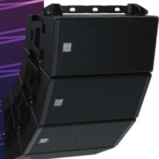
natural_image
Stacked black audio equipment with mesh backouts, displayed against a purple and white background (no visible text or symbols)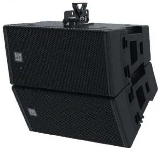
natural_image
Exterior view of a black industrial amplifier or speaker unit with ventilation grilles and mounting bracket (no visible text or symbols)Contents
Rigging 3
Cabinet Rigging Hardware....3
Flown Vertical Array....3
HF Left 3
HF Right 5
HRIG100 7
Flown Arrays with SXCF115 11
T8PB 19
POLERIG20....24
SBAR40 26
GSRIG20....28
Maintenance 34
Rigging
Cabinet Rigging Hardware
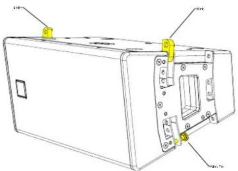
TORUS consists of a single point rigging system located on either side of the cabinet, all hardware is captive and can be stored conveniently for transportation.
natural_image
Technical line drawing of a rectangular electronic device with mounting holes and internal components (no text or symbols)Flown Vertical Array
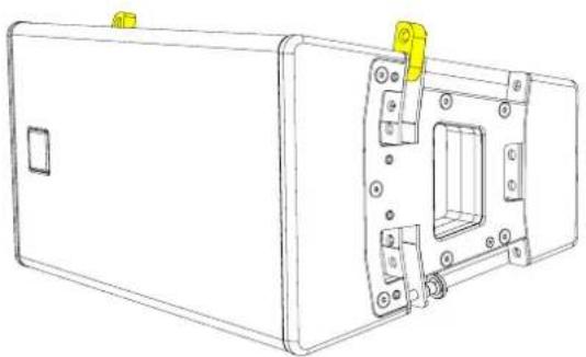
When flying TORUS vertically the HF horn can be positioned on the left or the right to create symmetrical system design.
natural_image
Technical line drawing of a rectangular electronic device with mounting holes and internal components (no text or symbols)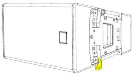
natural_image
Technical line drawing of a rectangular electronic device with mounting holes and a yellow tag (no text or symbols)Linking down - HF horn to the left Linking up - HF horn to the right
HF Left
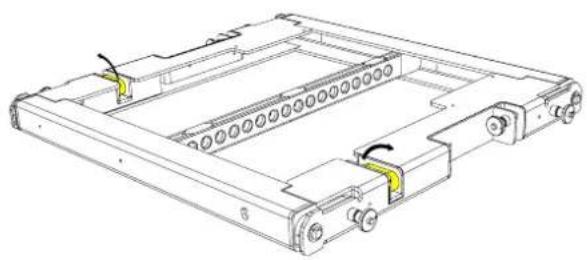
Release links from the stow position and rotate the T8 grid 180 degrees
natural_image
Technical line drawing of a mechanical frame assembly with no visible text or symbols
natural_image
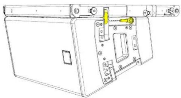
Technical line drawing of a mechanical component with no visible text or symbolsPosition the T8GRID on top of the first TORUS 8 cabinet, locate the links and insert the rigging pins. Make sure the cabinet is secured on both sides before lifting.
natural_image
Technical line drawing of a mechanical device with mounting bracket and internal components (no text or symbols)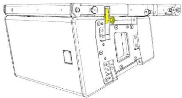
natural_image
Technical line drawing of a mechanical device with mounting bracket and internal components (no text or symbols)Lift the array to a height where the next cabinet can be positioned underneath. Either lift the cabinet into position or lower the array onto the cabinet below.
Remove the rigging pins from the cabinet above, rotate the links and insert the rigging pins to secure.
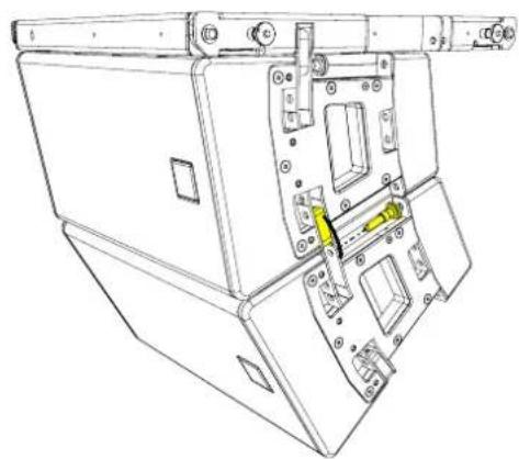
natural_image
Technical line drawing of a mechanical device with internal components and mounting brackets (no text or symbols)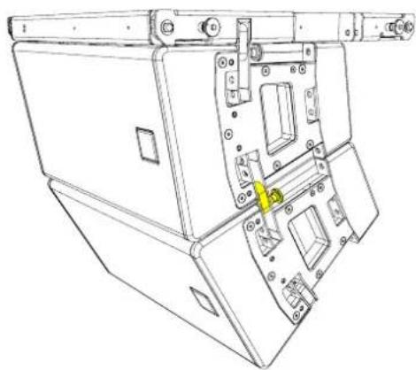
natural_image
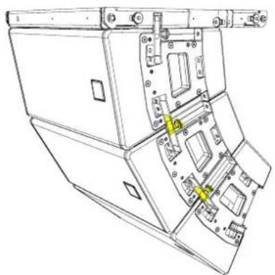
Technical line drawing of a mechanical device with internal components and mounting brackets (no text or symbols)Repeat the process until the desired number of cabinets have been vertically arrayed. A maximum of 6 cabinets can be flown from the T8GRID in the vertical orientation.
natural_image
Technical line drawing of a mechanical assembly with no visible text or symbolsHF Right
Rotate the T8GRID through 180° and release links from the stow position
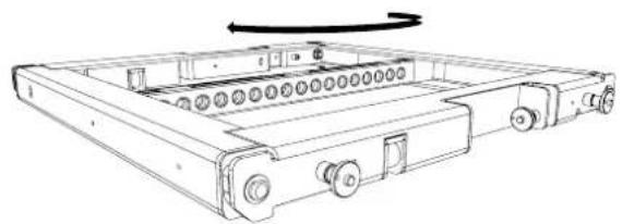
natural_image
Technical line drawing of a mechanical device with rollers and housing (no text or symbols)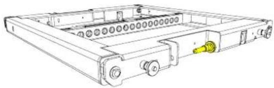
natural_image
Technical line drawing of a mechanical device with no visible text or symbolsPosition the T8GRID on top of the first TORUS 8 cabinet, rotate the links and insert the rigging pins. Make sure the cabinet is secured on both sides before lifting.
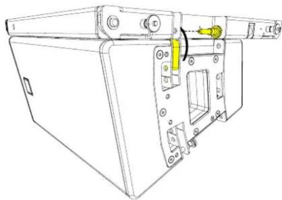
natural_image
Technical line drawing of a mechanical device with mounting holes and a yellow component inserted (no text or symbols)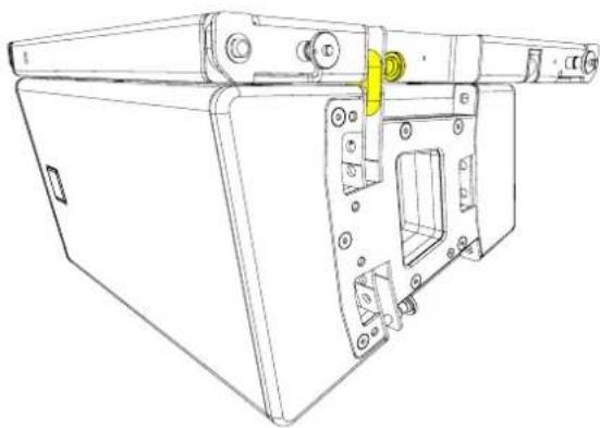
natural_image
Technical line drawing of a mechanical device with mounting brackets and a yellow component (no text or symbols)Lift the array to a height where the next cabinet can be positioned underneath. Either lift the cabinet into position or lower the array onto the cabinet below.
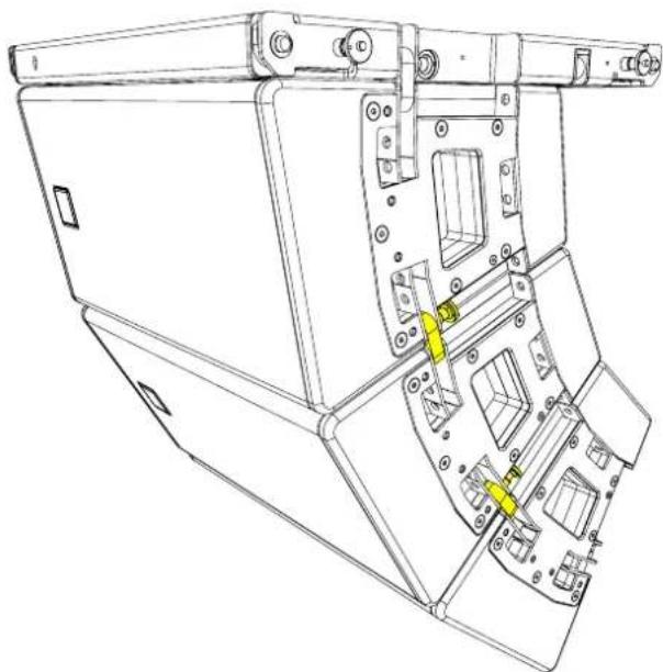
Remove the rigging pins from the cabinet below, rotate the links and insert the rigging pins to secure.
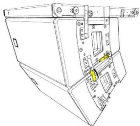
natural_image
Technical line drawing of a mechanical device with internal components and mounting holes (no text or symbols)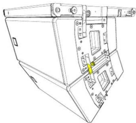
natural_image
Technical line drawing of a mechanical device with internal components and mounting holes (no text or symbols)Repeat the process until the desired number of cabinets have been vertically arrayed. A maximum of 6 cabinets can be flown from the T8GRID in the vertical orientation.
natural_image
Technical line drawing of a mechanical assembly with no visible text or symbolsHRIG100
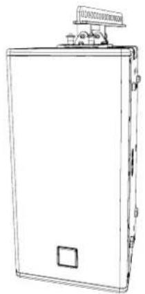
The HRIG100 is a rigging accessory used to suspend TORUS in a horizontal configuration. The HRIG100 can be mounted to a cabinet or between two cabinets, given the best options to suspend multiple cabinets.
HRIG100 can be mounted on the top or bottom of the cabinet in portrait mode, this allows the HF horn to be positioned at the top or the bottom of the array.
natural_image
Line drawing of a rectangular electronic device with a top-mounted top and side ports (no text or symbols)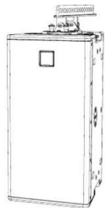
natural_image
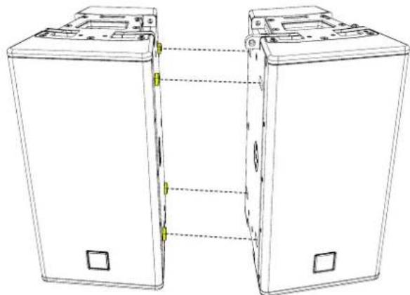
Line drawing of a rectangular industrial machine with a top-mounted top unit (no text or symbols visible)Link cabinets together by aligning the skids to the adjacent cabinet.
natural_image
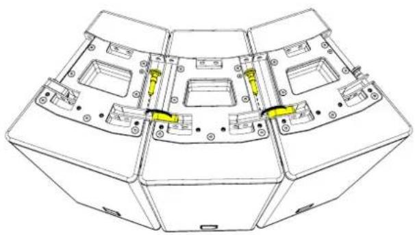
Line drawing of two rectangular electronic devices connected by a vertical line, with no visible text or symbols.Remove pins and rotate the links on the top of the cabinets
natural_image
Technical line drawing of a multi-chamber electronic device casing with mounting holes and internal compartments (no text or symbols)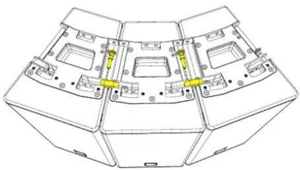
natural_image
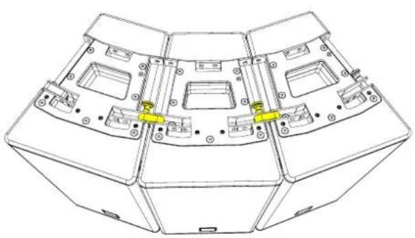
Technical line drawing of a multi-chamber electronic device casing with mounting holes and internal compartments (no text or symbols)Replace the pins to lock the cabinets together
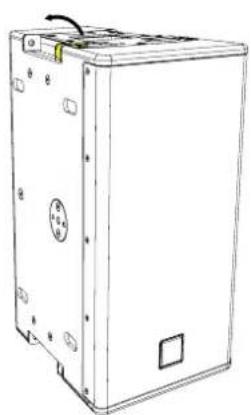
Tip the array and remove the rigging pins on the bottom of the array. Rotate the links into position.
natural_image
Technical line drawing of a mechanical housing or enclosure with multiple compartments and mounting points (no text or symbols)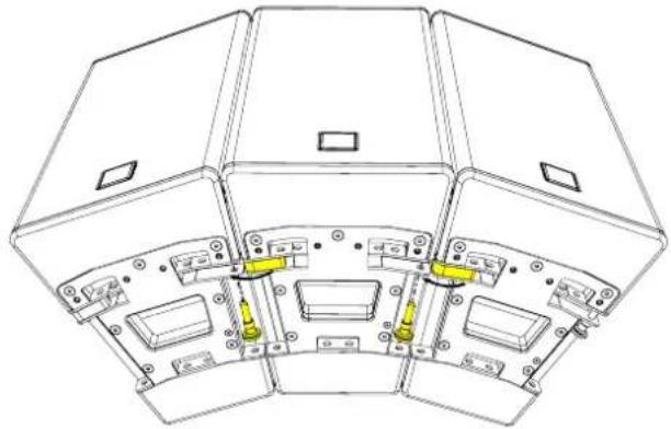
natural_image
Technical line drawing of a multi-panel electronic device with mounting holes and internal components (no text or symbols)Replace the pins to link the bottom of the cabinets together.
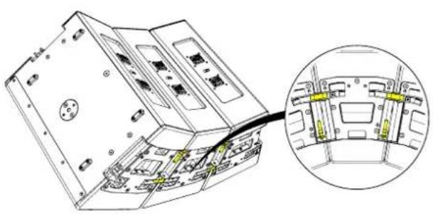
natural_image
Technical line drawing of an electronic device showing internal components and a close-up inset (no text or symbols)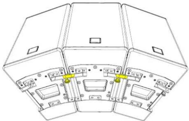
natural_image
Technical line drawing of a multi-layered mechanical or electronic component assembly (no text or symbols)Attach the HRIG100 making sure all four pins (two back and two front) locate and lock into position
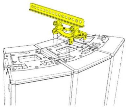
natural_image
Technical line drawing of a mechanical assembly with a yellow robotic arm mounted on a base plate (no text or symbols visible)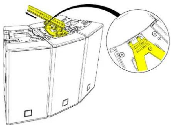
natural_image
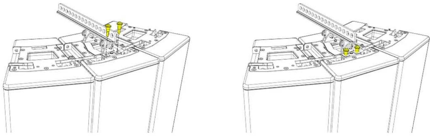
Diagram of a battery pack with a yellow component being inserted, showing internal structure and a magnified view (no text or symbols)WARNING!
The HRIG100 is only secure when the two locking pins have been inserted and locked into place.
natural_image
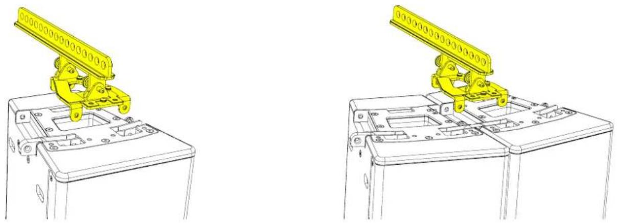
Technical line drawings of a mechanical device with multiple ports and mounting brackets (no text or symbols)Two mounting options are available depending on the configuration. The T12HRIG can be mounted directly to a TORUS or between cabinets.
natural_image
Technical line drawings of a yellow robotic device mounted on a base panel, shown from two different angles (no text or symbols present)When connecting multiple TORUS together, the top link needs to be rotated before mounting the HRIG100 between two cabinets.
natural_image
Line drawing of a rectangular electronic device with mounting holes and a central circular component (no text or symbols)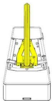
natural_image
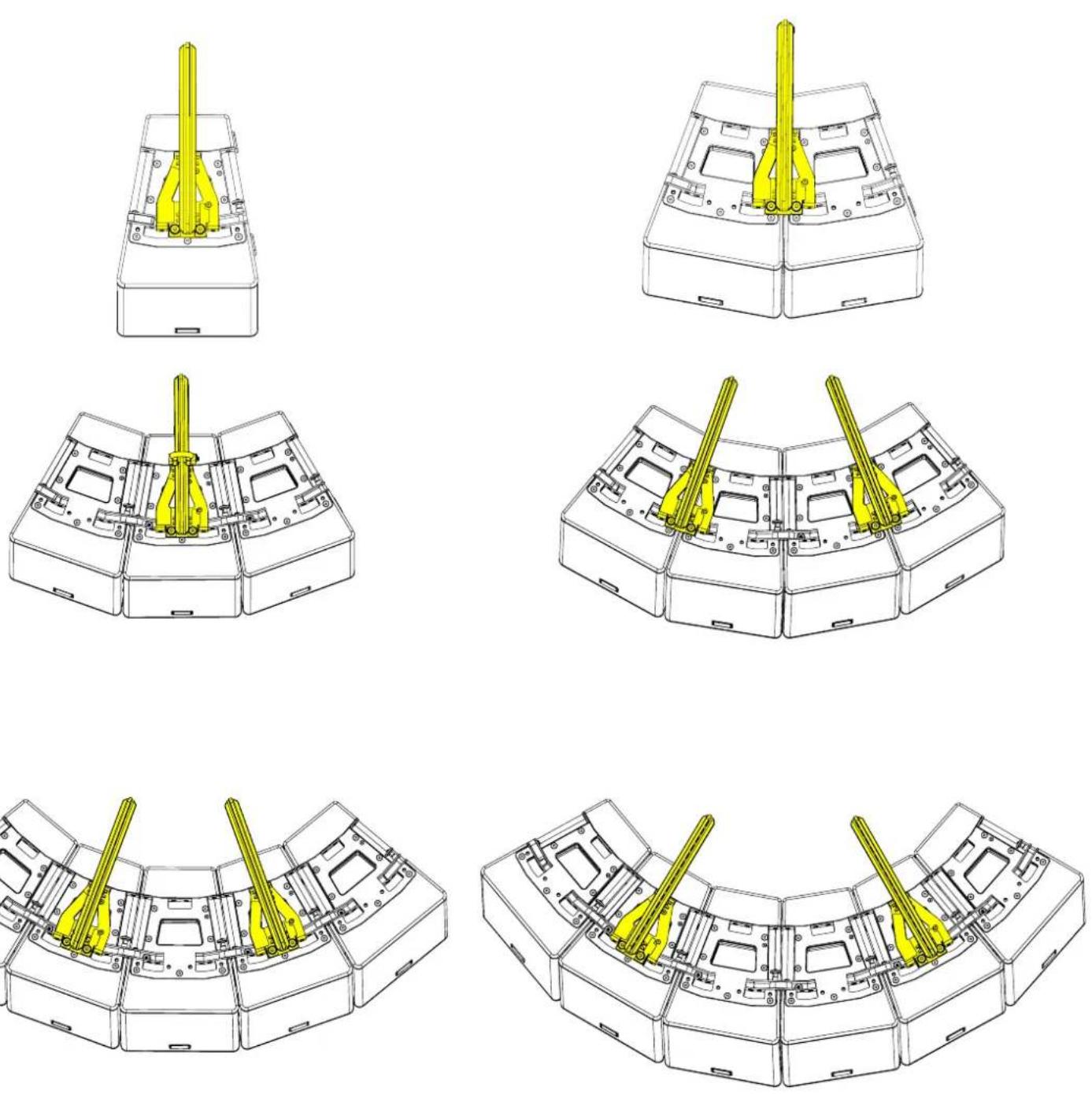
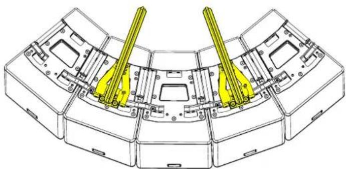
Technical line drawing of a yellow mechanical component with mounting holes and a central vertical shaft (no text or symbols)A maximum of 6 cabinets can be suspended using 2 HRIG100's. Below shows the number of HRIG100's that must be used for a given combination
natural_image
Technical line drawing of a multi-stage electronic device casing with yellow connectors (no text or symbols)Flown Arrays with SXCF115
Position the WPMSXGRIDT on top of the SXCF115 cabinet
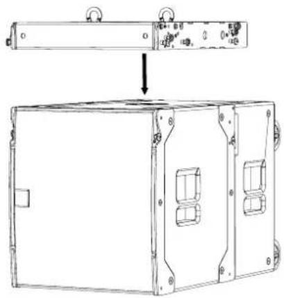
Remove the pins from the from SXCF115 to release the links.
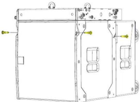
natural_image
Technical line drawing of a device casing with mounting holes and internal compartments (no text or symbols)Rotate the front links and lift the rear links to align with the pin holes in the WPMSXGRIDT.
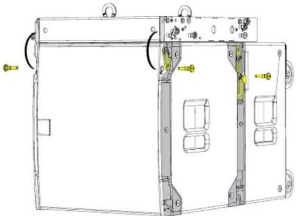
natural_image
Technical line drawing of a mechanical device with internal components and mounting holes (no text or symbols)Replace the pins to link and lock the SXCF115 securely to the WPMGRIDT
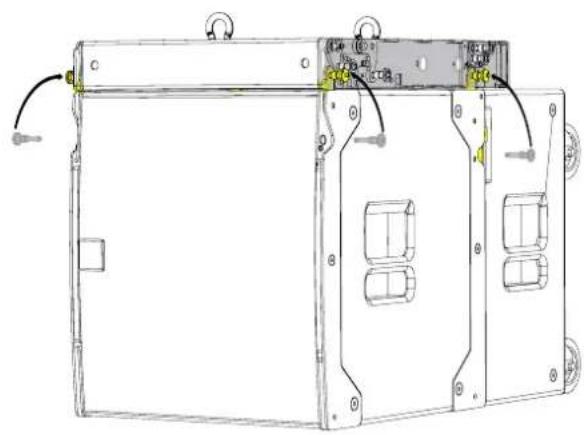
natural_image
Technical line drawing of a mechanical device with mounting holes and internal components (no text or symbols)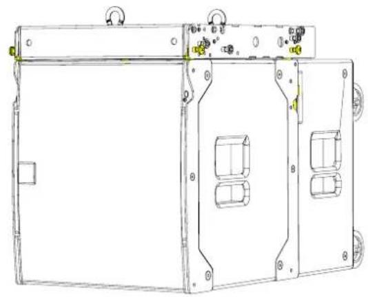
natural_image
Technical line drawing of a mechanical enclosure or enclosure with multiple compartments and mounting holes (no text or symbols)Place cabinets on top of each other.
Remove the rigging pins from the cabinet above, rotate the links and insert the rigging pins to secure.
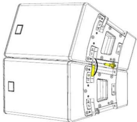
natural_image
Technical line drawing of a mechanical housing or enclosure with internal components and mounting holes (no text or symbols)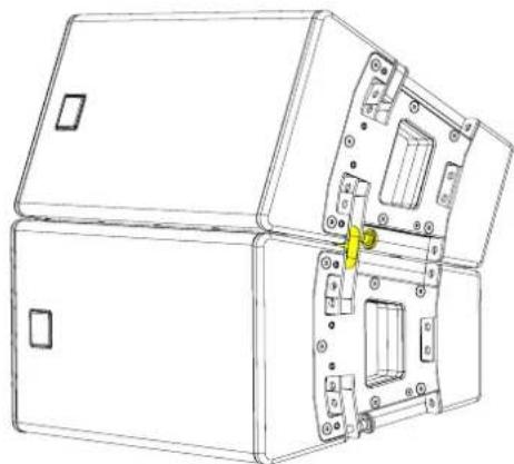
natural_image
Technical line drawing of a device housing with internal components and mounting holes (no text or symbols)The T8GRID is also used as a conversion frame for the SXCF115 & T8 combined array.
Horn Right
Remove the sub link pins and rotate the links
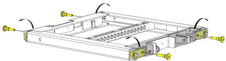
natural_image
Technical diagram of a mechanical assembly with labeled components and directional arrows (no text or symbols)Place the T8GRID on top of the T8 cabinets, remove the link pins and rotate the T8 links. Replace the pins to lock the grid into position
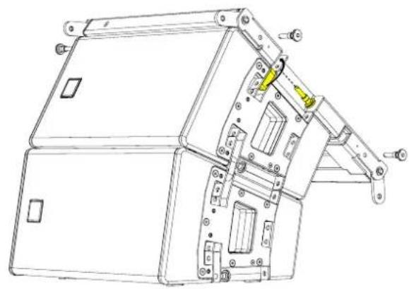
natural_image
Technical line drawing of a mechanical device with internal components and mounting brackets (no text or symbols)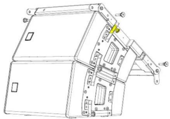
natural_image
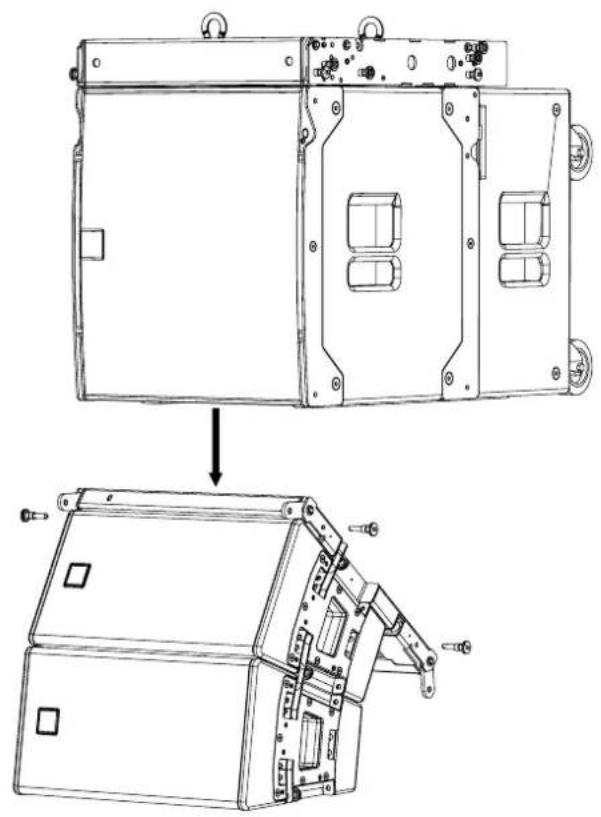
Technical line drawing of a mechanical device with mounting brackets and internal components (no text or symbols)Position the T8 cabinets below the SXCF115 and lower the SXCF115 to connect the front links.
natural_image
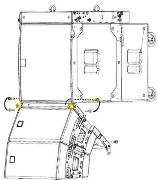
Technical line drawing of a device housing assembly showing internal components and mounting brackets (no text or symbols)Rotate the front T8GRID sub links and connect to the front of the SXCF115 using the front rigging pins from the T8GRID
natural_image
Technical line drawing of a mechanical device with internal components and mounting holes (no text or symbols)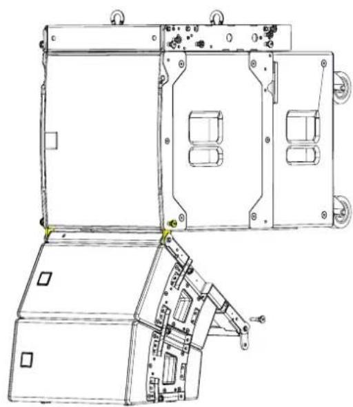
natural_image
Technical line drawing of a mechanical device with mounting brackets and internal components (no text or symbols)Rotate the rear T8GRID sub links Swing the rear of the T8GRID to align the rear links
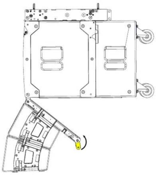
natural_image
Technical line drawing of a mechanical assembly with mounting holes and wheels, showing internal components and a highlighted view (no text or symbols)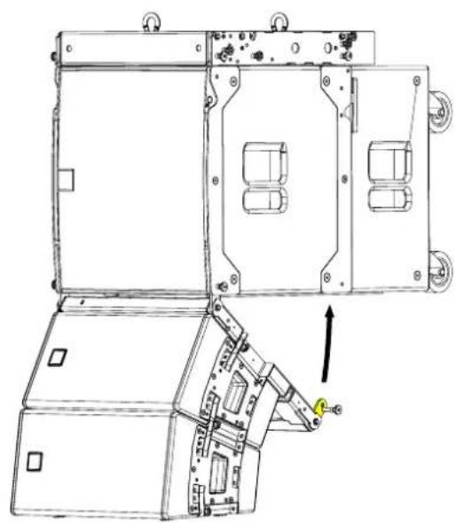
natural_image
Technical line drawing of an open industrial enclosure with internal compartments and a mechanical component below (no text or symbols)Connect to the rear of the SXCF115 using the rear rigging pins from the T8GRID
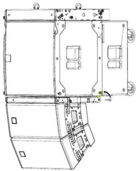
natural_image
Technical line drawing of a mechanical device with internal components and mounting holes (no text or symbols)Horn left
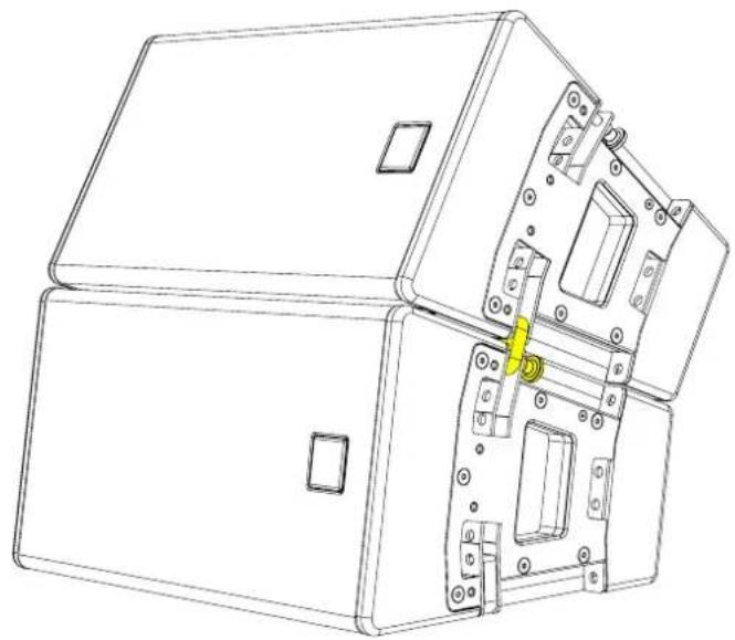
Place cabinets on top of each other.
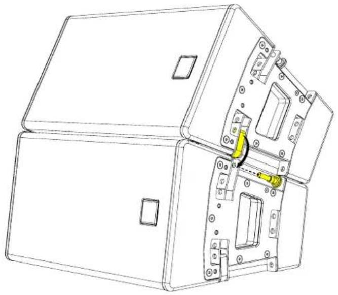
natural_image
Technical line drawing of a mechanical housing with internal components and mounting holes (no text or symbols)Remove the rigging pins from the cabinet below, rotate the links and insert the rigging pins to secure.
natural_image
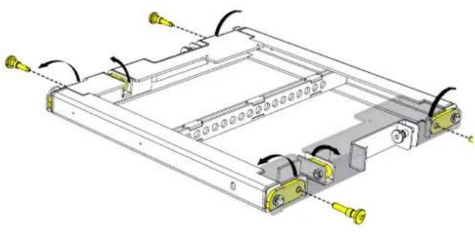
Technical line drawing of a mechanical housing or enclosure with internal components and mounting holes (no text or symbols)Remove the link pins and rotate the links. Links for T8 are held by a magnet, make sure they are moved from the stow position before attaching to the T8 array
natural_image
Technical diagram of a mechanical assembly with no visible text or symbols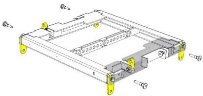
natural_image
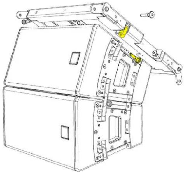
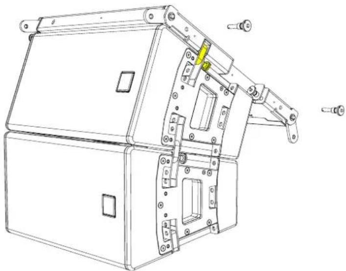
Technical line drawing of a mechanical frame assembly with yellow connectors and mounting holes (no text or symbols)Rotate the T8GRID through 180° and place on top of the T8 cabinets. Remove the link pins from the cabinet.
natural_image
Technical line drawing of a mechanical device with mounting brackets and internal components (no text or symbols)Replace the pins to lock the grid into position
natural_image
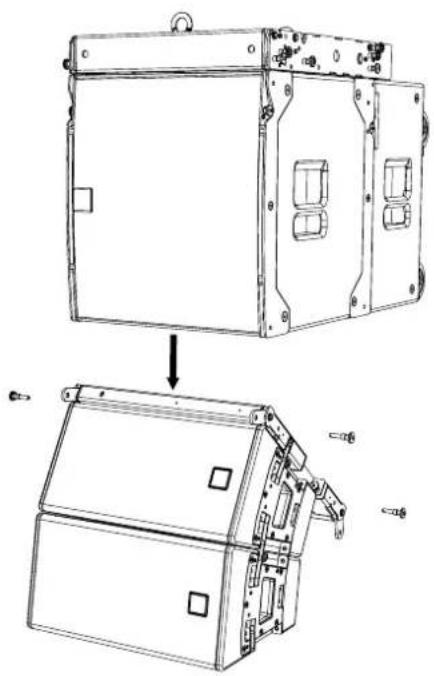
Technical line drawing of a mechanical device with multiple arms and mounting holes (no text or symbols)Position the T8 cabinets below the SXCF115 and lower the SXCF115 to connect the front links.
natural_image
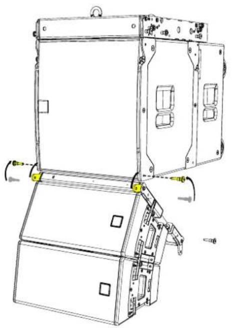
Technical line drawing of a device housing assembly, showing front and side views (no text or symbols)Rotate the front T8GRID sub links and connect to the front of the SXCF115 using the front rigging pins from the T8GRID
natural_image
Technical line drawing of a mechanical device with mounting base and internal components (no text or symbols)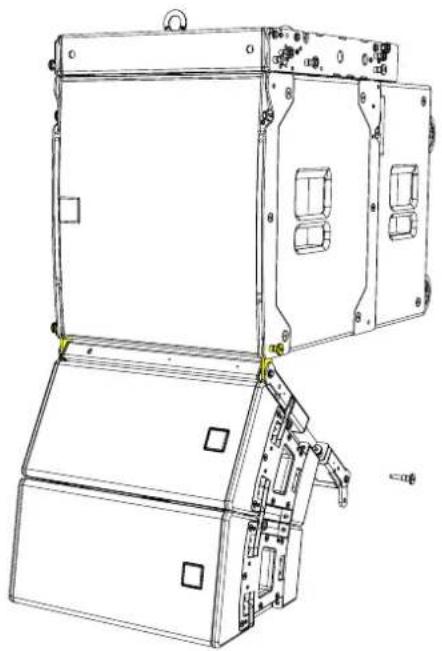
natural_image
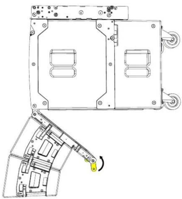
Technical line drawing of a mechanical device with mounting brackets and internal compartments (no text or symbols)Rotate the rear T8GRID sub links Swing the rear of the T8GRID to align the rear links
natural_image
Technical line drawing of a mechanical device with mounting holes and a highlighted lever mechanism (no text or symbols)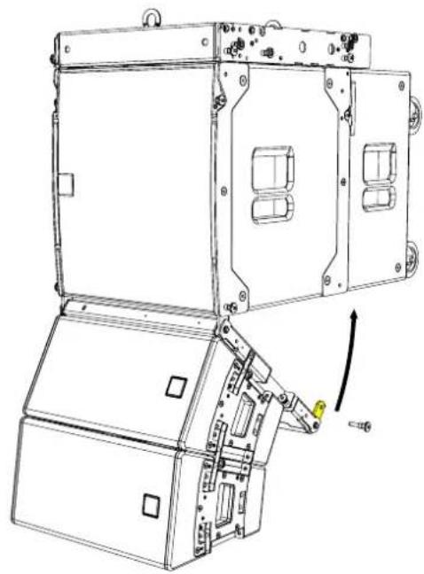
natural_image
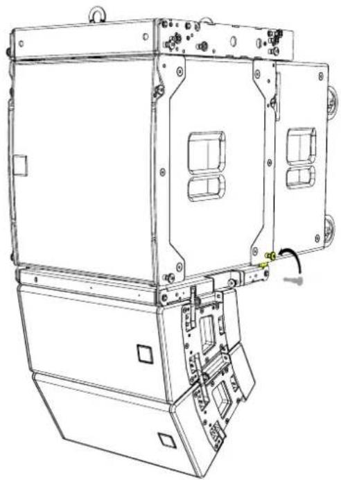
Technical line drawing of a mechanical device with mounting brackets and internal components, showing no text or symbols.Connect to the rear of the SXCF115 using the rear rigging pins from the T8GRID
natural_image
Technical line drawing of an industrial control unit with internal compartments and mounting points (no text or symbols)T8PB
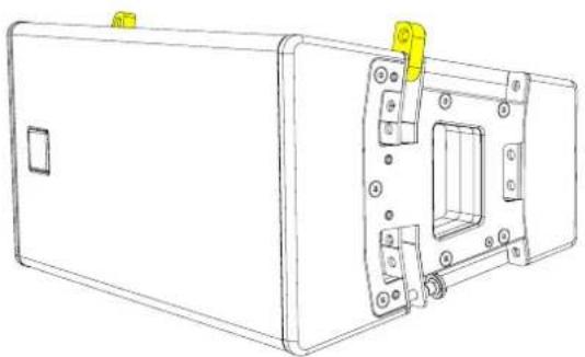
A rigging bar that can be mounted at the top and the bottom of the array allows extreme array deployment for installations.
When flying TORUS vertically the HF horn can be positioned on the left or the right to create symmetrical system design
natural_image
Technical line drawing of a rectangular electronic device with mounting holes and internal components (no text or symbols)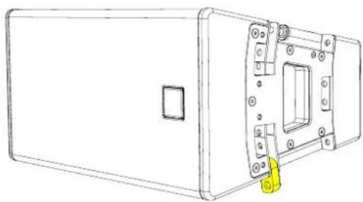
natural_image
Technical line drawing of a rectangular electronic device with mounting holes and a highlighted internal component (no text or symbols)Linking up - HF horn to the right Linking down - HF horn to the left
Horn Left
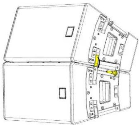
Place cabinets on top of each other. Remove the rigging pins from the cabinet below, rotate the links and insert the rigging pins to secure. Make sure the cabinet is secured on both sides.
Repeat the process until the desired number of cabinets have been vertically arrayed. A maximum of 6 cabinets can be flown from the T8PB in the vertical orientation.
natural_image
Technical line drawing of a computer case with internal components and mounting holes (no text or symbols)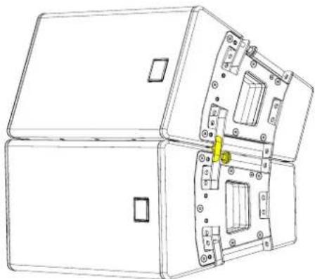
natural_image
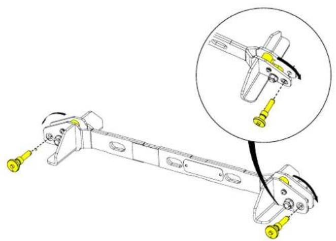
Technical line drawing of an open industrial enclosure with internal components (no text or symbols)Rotate the links and position the T8PB on top of the TORUS cabinet
natural_image
Mechanical assembly diagram showing a lever mechanism with yellow connectors and a magnified inset of the component detail (no text or symbols)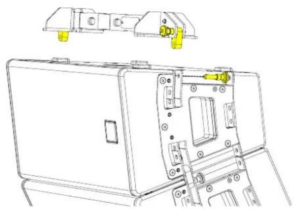
natural_image
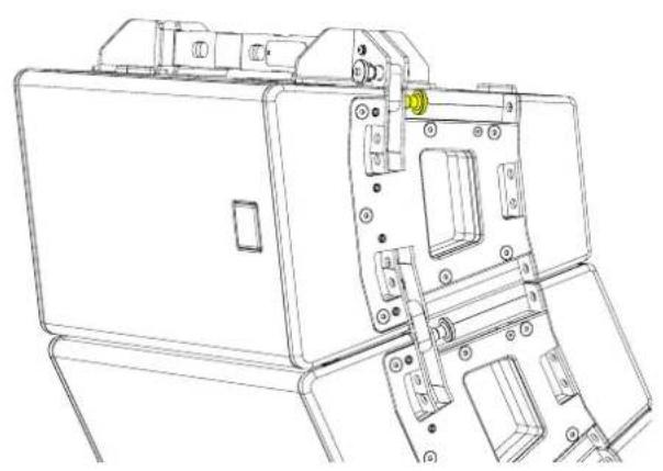
Technical line drawing of a mechanical device with internal components and mounting bracket (no text or symbols)Replace the rigging pins on both sides of the cabinet to secure.
natural_image
Technical line drawing of a mechanical device with internal components and mounting brackets (no text or symbols)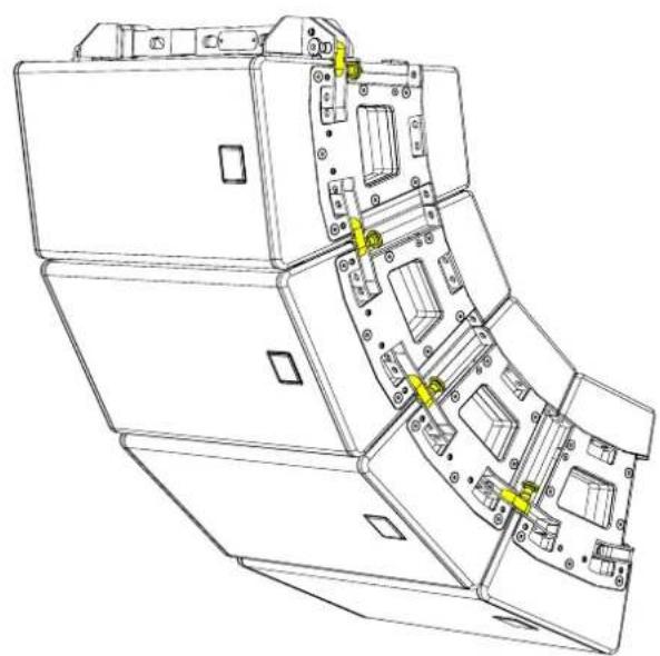
natural_image
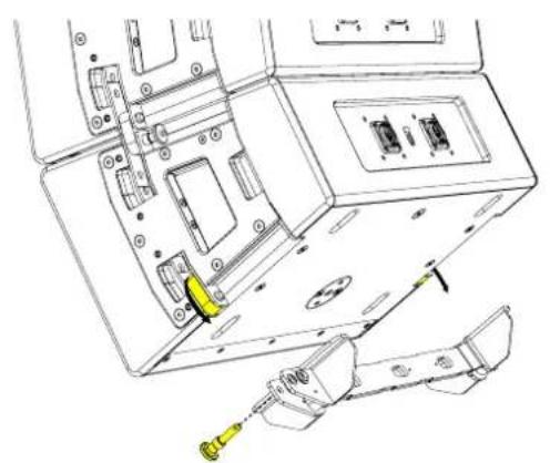
Technical line drawing of a mechanical assembly with multiple components and yellow directional arrows indicating movement or force (no text or symbols present)A second T8PB can be linked to the bottom of the array and used to achieve angles that are not possible with a single T8PB. This configuration can also be used to secure the array.
Rotate the links on the bottom cabinet and remove the rigging pins from the PB8.
Secure the PB8 into the cabinet links and replace the rigging pins
natural_image
Technical line drawing of a mechanical assembly with no visible text or symbols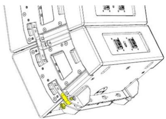
natural_image
Technical line drawing of an electronic device interior with ports and connectors (no text or symbols)Horn Right
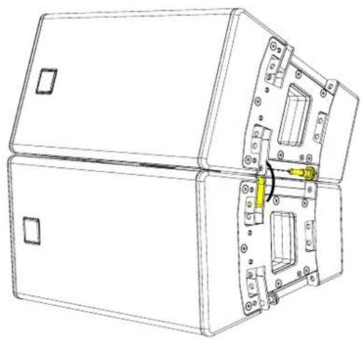
Place cabinets on top of each other. Remove the rigging pins from the cabinet above, rotate the links and insert the rigging pins to secure. Make sure the cabinet is secured on both sides.
natural_image
Technical line drawing of a mechanical device with internal components and mounting holes (no text or symbols)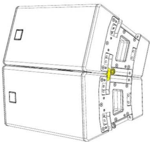
natural_image
Technical line drawing of a mechanical housing or enclosure with internal components and mounting holes (no text or symbols)Repeat the process until the desired number of cabinets have been vertically arrayed. A maximum of 6 cabinets can be flown from the T8PB in the vertical orientation.
Position the T8PB on top of the TORUS cabinet, remove the rigging pins and rotate the links from the cabinet below.
Replace the rigging pins on both sides of the PB8 to secure to the array

natural_image
Technical line drawing of a mechanical assembly with mounting brackets and yellow connectors (no text or symbols)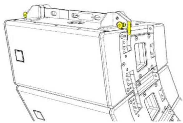
natural_image
Technical line drawing of a mechanical device with mounting holes and internal components (no text or symbols)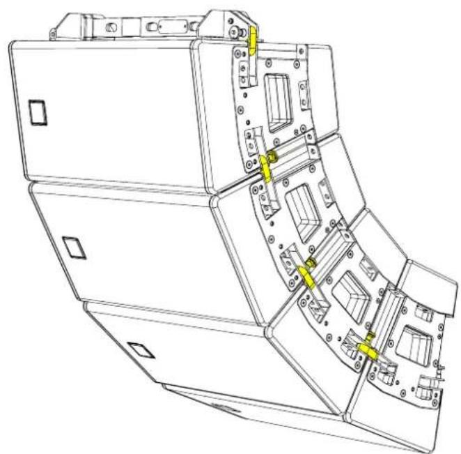
natural_image
Technical line drawing of a mechanical device with internal components and mounting holes (no text or symbols)An additional T8PB can be linked to the bottom of the array and used to achieve angles that are not possible with a single T8PB. This configuration can also be used to secure the array.
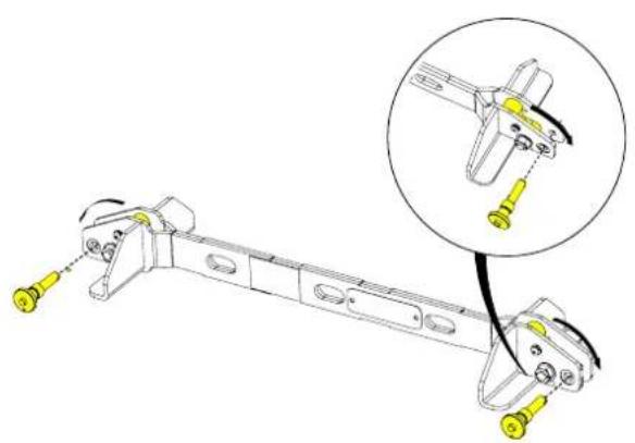
Remove the rigging pins from the PB8 and rotate the links
Replace the rigging pins to lock the links in place
natural_image
Mechanical linkage assembly diagram with highlighted detail (no text or symbols)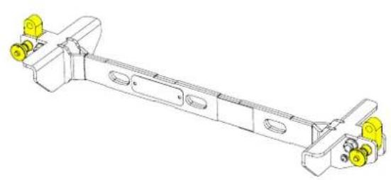
natural_image
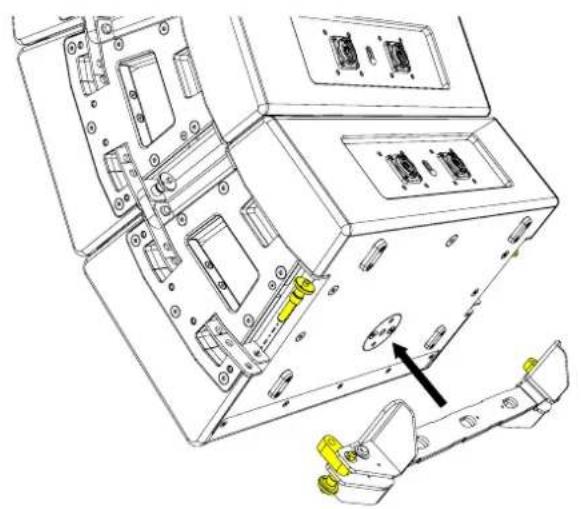
Technical line drawing of a mechanical assembly with yellow connectors and mounting holes (no text or symbols)Secure the PB8 into the cabinet rigging hardware and replace the rigging pins
natural_image
Technical line drawing of an electronic device showing internal components and a highlighted assembly (no text or symbols)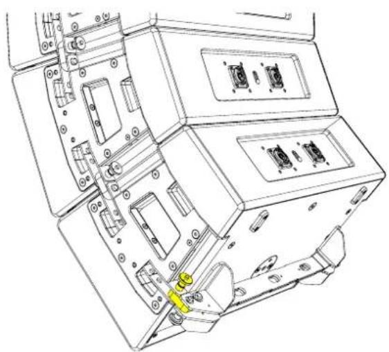
natural_image
Technical line drawing of an electronic device casing with internal compartments and mounting holes (no text or symbols)POLERIG20
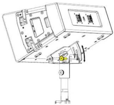
The vertical angle for a pole mounted TORUS can be adjusted and secured with a rigging pin. Angles available are
-10° to -30° in 5° increments
There are two mounting plates, one on either the top or the bottom of the cabinet (when in landscape). Decide which orientation you want the HF horn (left side or right side)
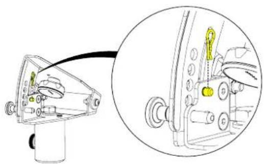
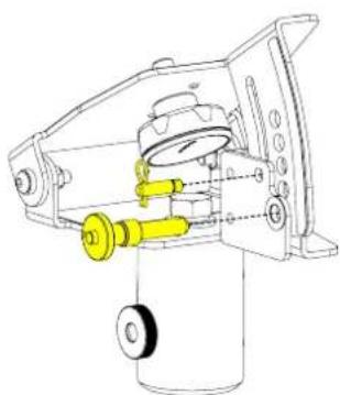
Remove the R-Clip from the safety pin Remove the safety and rigging pin from the POLERIG20
natural_image
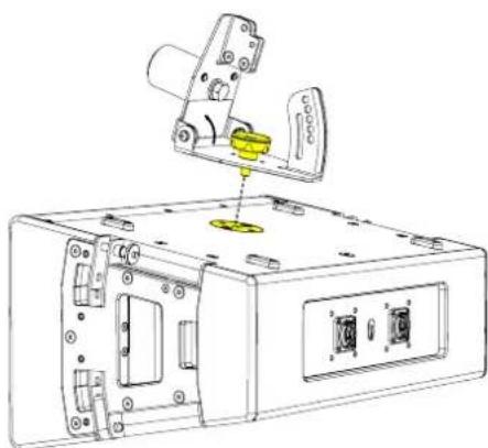
Technical diagram of a mechanical device with a close-up view showing internal components (no text or symbols)Locate the POLERIG20 into the mounting plate
natural_image
Technical line drawing of a mechanical device with yellow components and mounting holes (no text or symbols)Tighten the handwheel until secure
natural_image
Technical line drawing of a mechanical device with a yellow component inserted, showing internal components and mounting holes (no text or symbols)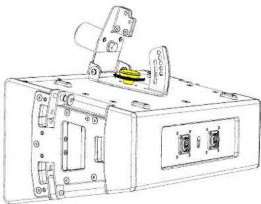
natural_image
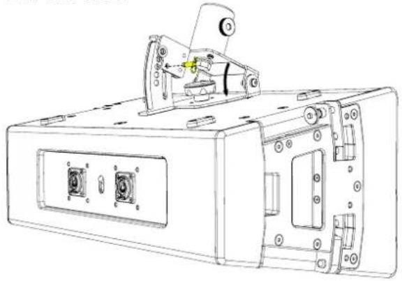
Technical line drawing of a mechanical device with mounting brackets and a yellow component (no text or symbols)Rotate the base of the POLERIG20 and replace the safety pin, making sure it engages with the slot.
natural_image
Technical line drawing of a mechanical device with mounting holes and internal components (no text or symbols)Before placing the cabinet onto a speaker stand or distance pole, undo the thumb wheel.
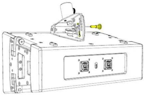
Replace the R-Clip and select the desired angle
natural_image
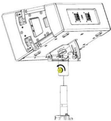
Technical line drawing of a device rear panel with ports and a connector (no text or symbols)Place the cabinet on the and secure by tightening the thumb wheel
natural_image
Technical line drawing of a mechanical assembly with no visible text or symbols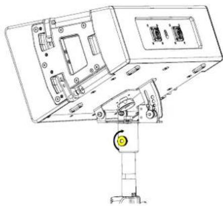
natural_image
Technical line drawing of a mechanical assembly with internal components and a yellow circular component (no text or symbols)The angle can be changed by removing the rigging and selecting one of the 5 holes available
natural_image
Technical line drawing of a device rear panel with internal components and a yellow component, no text or symbols present.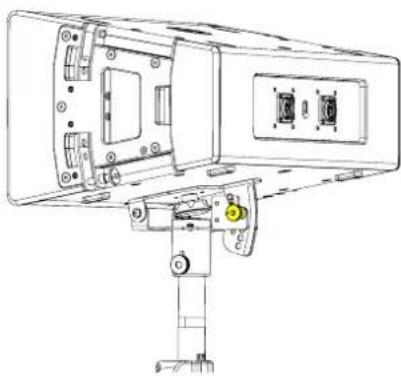
natural_image
Technical line drawing of a mechanical device with mounting brackets and a vertical support (no text or symbols)SBAR40
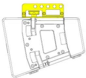
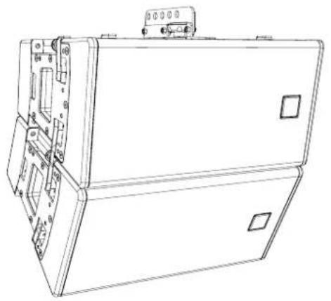
The SBAR40 is a simple accessory allowing 2 x T8 cabinets to be flown using 10 predetermined angles.
The SBAR can be mounted -
Towards the rear for - angles
natural_image
Technical line drawing of a device casing with internal components and mounting holes (no text or symbols)Towards the front for + angles.
natural_image
Technical line drawing of a mechanical housing or enclosure with mounting brackets and internal components (no text or symbols)Please refer to DISPLAY 3 for angle options
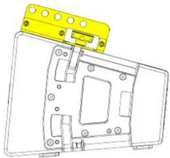
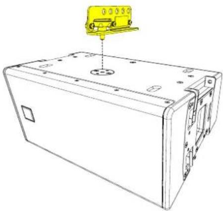
There are two mounting plates, one on either the top or the bottom of the cabinet (when in landscape). Decide which orientation you want the HF horn (left side or right side)
Align the two pins and place the SBAR40 onto the mounting bracket.
Turn the handwheel and tighten securely
natural_image
Technical line drawing of a rectangular electronic device with mounting holes and a yellow component above it (no text or symbols)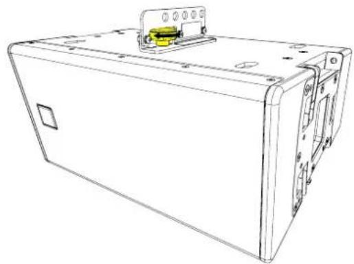
natural_image
Line drawing of a rectangular electronic device with mounting holes and a yellow component on top (no text or symbols)Mounting options
Horn Left
natural_image
Line drawing of a mechanical device with front panel and side ports (no text or symbols)Horn Right
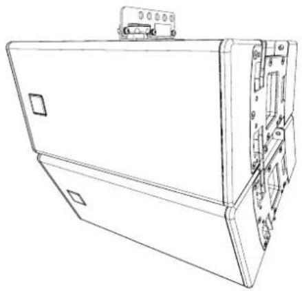
natural_image
Line drawing of a rectangular electronic device with internal components and mounting bracket (no text or symbols)A half coupler adaptor can be used to suspend a single cabinet from the SBAR40.
Remove the R-Clip to release the pin
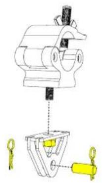
Secure the half coupler to the adaptor
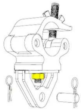
natural_image
Technical line drawing of a mechanical clamp or clamping device with no visible text or symbolsPosition the adaptor in line with 1 of the 5 holes on the SBAR40 and replace the link pin and R-Clip
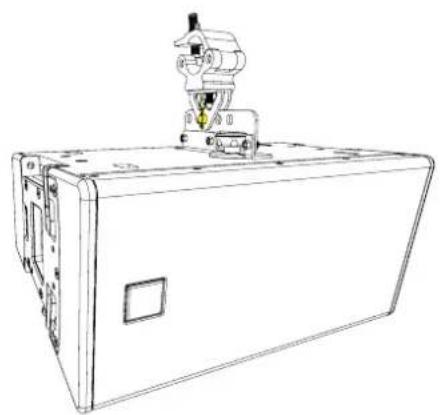
natural_image
Line drawing of a mechanical device with a mounted sensor or actuator (no text or symbols visible)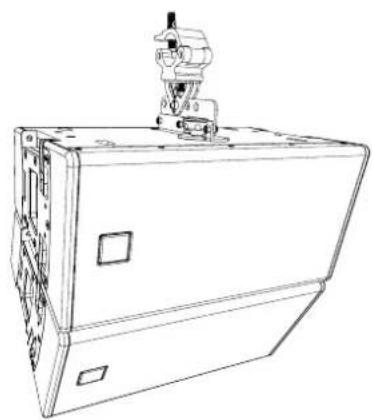
natural_image
Line drawing of a mechanical device with a mounted sensor or actuator (no text or symbols visible)GSRIG20
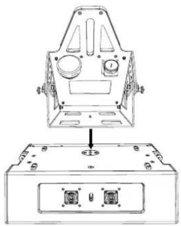
There are two mounting plates, one on either the top or the bottom of the cabinet (when in landscape). Decide which orientation you want the HF horn (left side or right side)
Align the two pins and place the GSRIG20 onto the mounting bracket
natural_image
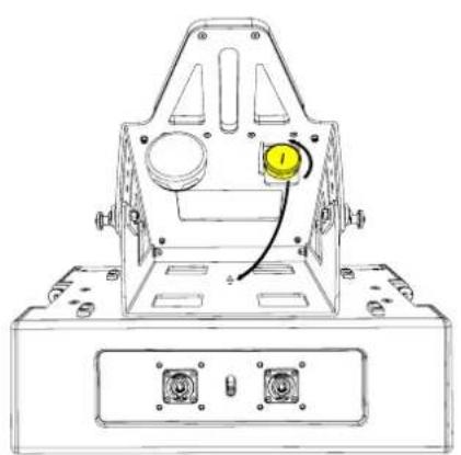
Technical line drawing of a mechanical housing assembly with mounting holes and internal components (no text or symbols)Remove the M10 handwheel from the stowing plate and secure to the plate through the mounting hole on the top plate of the GS20
natural_image
Technical line drawing of a mechanical component with mounting holes and a yellow indicator light (no text or symbols)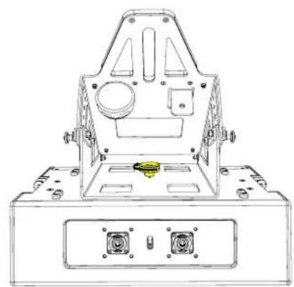
natural_image
Technical line drawing of a mechanical component with mounting holes and a central hub (no text or symbols)Application example
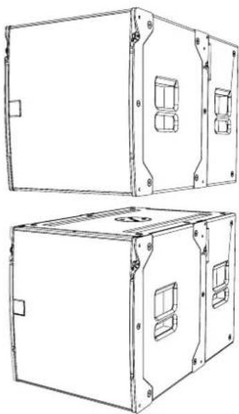
Stack 2 x SXCF115 (one on top of the other).
natural_image
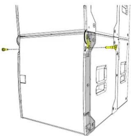
Technical line drawing of two 3D rectangular electronic enclosure units with mounting holes and internal compartments (no text or symbols)Remove the pins from the front SXCF115 to release the links.
Rotate the links and line them up with the pin holes on the cabinet above.
natural_image
Technical line drawing of a mechanical assembly with no visible text or symbols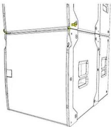
natural_image
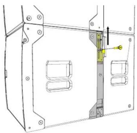
Technical line drawing of a mechanical or architectural component with no visible text, numbers, or symbols.Remove the rear pins and lift the link Insert the pins into the bottom of the top SXCF115 to lock the cabinets together
natural_image
Technical line drawing of a mechanical housing or enclosure with internal components and mounting holes (no text or symbols)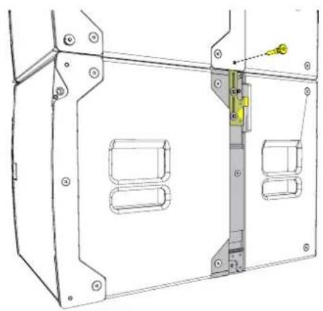
natural_image
Technical line drawing of a mechanical housing or enclosure with internal components and mounting holes (no text or symbols)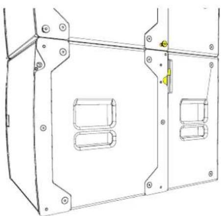
natural_image
Technical line drawing of a mechanical housing or enclosure with mounting holes and internal compartments (no text or symbols)Place the assembly onto the top of the SXCF115 stack
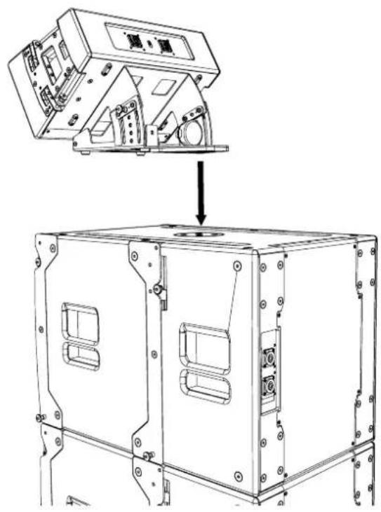
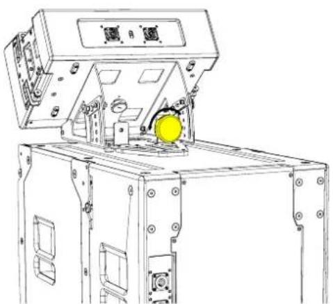
Remove the M20 handwheel from the stowing plate and secure to the M20 pole mount through the hole on the base plate of the GSRIG20
natural_image
Technical line drawing of a mechanical device with mounting brackets and a yellow circular component (no text or symbols)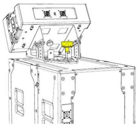
natural_image
Technical line drawing of a mechanical assembly with no visible text or symbolsTighten the M20 handwheel securely
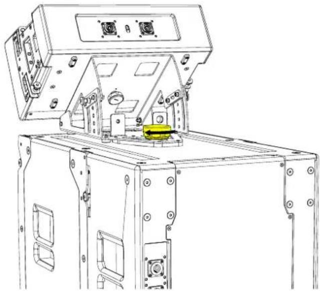
natural_image
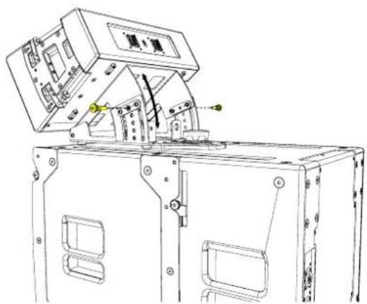
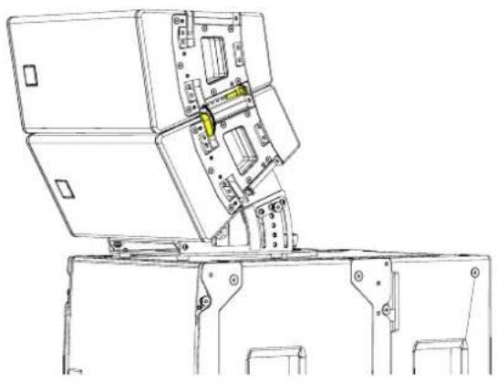
Technical line drawing of a mechanical assembly with mounting brackets and a yellow component (no text or symbols)The angle of the GSRIG20 can be adjusted before adding more T8 cabinets, by removing the rigging pins from the side plates.
Replace the pins at the desired angle to lock into place
natural_image
Technical line drawing of a mechanical device with no visible text or symbols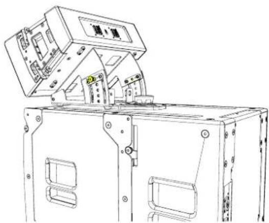
natural_image
Technical line drawing of a mechanical device with open lid and internal components (no text or symbols)Place a cabinet on top and remove the rigging pins from the cabinet above, rotate the links.
Replace the rigging pins to secure. Make sure the cabinet is secured on both sides.
natural_image
Technical line drawing of a mechanical device with mounting brackets and internal components (no text or symbols)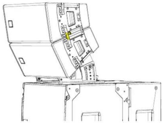
natural_image
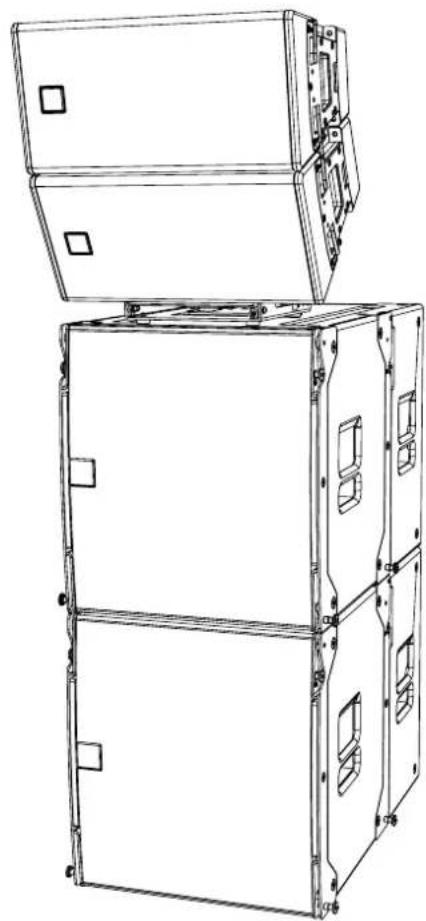
Technical line drawing of a mechanical assembly with no visible text or symbolsA maximum of 3 can be arrayed on top of the T8GSRIG. And any Martin Audio subwoofer that has an M20 pole mount can be used with this accessory. SCX(F)115, SXC(F)118, SX218
natural_image
Technical line drawing of a multi-tiered industrial equipment cabinet with mounting holes and internal compartments (no text or symbols)Maintenance
To perform maintenance on this product the following tools listed below are needed.
4mm hex tool
5mm hex tool
No. 2 Posi Screwdriver
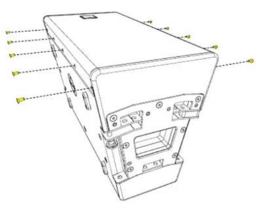
Replacing the LF Driver -
Remove the countersunk hex fasteners from the grille. (4mm hex tool)
natural_image
Technical line drawing of a device casing with labeled components (no text or symbols present)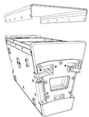
natural_image
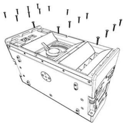
Technical line drawing of a mechanical housing or enclosure component (no text or symbols)Remove the No. 8 Flange head screws Lift the horn assembly out of the enclosure and
disconnect the terminal spades on the LF and HF drivers
natural_image
Technical line drawing of a mechanical device casing with mounting holes and internal components (no text or symbols)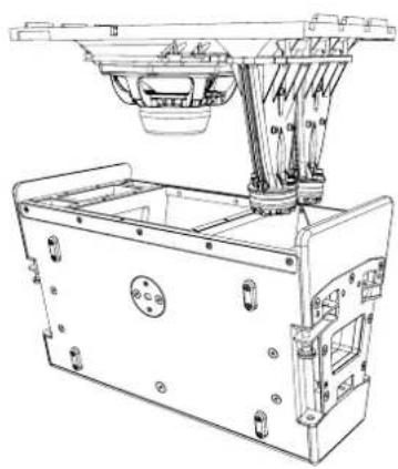
natural_image
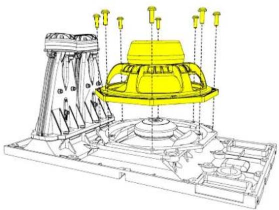
Technical line drawing of a mechanical device with no visible text or symbolsRemove the Pan head fasteners with a posi head screwdriver to remove the LF driver
natural_image
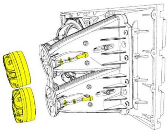
Technical line drawing of a mechanical assembly with yellow components and mounting brackets (no text or symbols)Remove the hex bolts using the M5 hex tool to remove the HF drivers
natural_image
Technical line drawing of a mechanical assembly with two yellow components (no text or symbols)Martin Audio Limited
Century Point
Halifax Road
Cressex Business Park
FOR SALES ENQUIRIES:
High Wycombe
Buckinghamshire
HP12 3SL
England
UK
Telephone: +44 (0)1494 535312
E-mail: info@martin-audio.com
NORTH AMERICA
Telephone: 323-381-5310
www.martin-audio.com
All information is Copyright © 2023 Martin Audio Ltd.
Martin Audio, the Martin Audio logo and Hybrid are registered trademarks of Martin Audio Ltd. in the United Kingdom, United States and other countries; all other Martin Audio trademarks are the property of Martin Audio Ltd.
Brand : Martin Audio
Model : TORUS T820
Category : Loudspeaker