MKS-E1620 - Uncategorized SONY - Free user manual and instructions
Find the device manual for free MKS-E1620 SONY in PDF.

| Product Type | Remote Control Panel |
| Model | MKS-E1620 |
| Brand | Sony |
| Dimensions (approx.) | 420 x 220 x 90 mm (16.5 x 8.7 x 3.5 in) |
| Weight | 2.5 kg (5.5 lbs) |
| Power Supply | DC 12 V, 2 A |
| Power Consumption | 24 W (max) |
| Number of Channels | 16 |
| Supported Cameras | Sony HDC series, PXW series |
| Control Interface | Ethernet (RJ-45) or RS-422 |
| Display | Backlit LCD, 2-line x 16 characters |
| Keypad | Rubber keys with LED indicators |
| Audio Communication | Built-in microphone and speaker |
| Operating Temperature | 0°C to 40°C (32°F to 104°F) |
| Storage Temperature | -20°C to 60°C (-4°F to 140°F) |
| Humidity | 10% to 90% non-condensing |
| Mounting | Desktop or rackmount optional |
| Included Accessories | AC adapter, manual, Ethernet cable |
| Cleaning | Wipe with a soft, dry cloth. Do not use solvents. |
| Spare Parts Availability | Contact authorized Sony service center |
Frequently Asked Questions - MKS-E1620 SONY
User questions about MKS-E1620 SONY
0 question about this device. Answer the ones you know or ask your own.
Ask a new question about this device
Download the instructions for your Uncategorized in PDF format for free! Find your manual MKS-E1620 - SONY and take your electronic device back in hand. On this page are published all the documents necessary for the use of your device. MKS-E1620 by SONY.
USER MANUAL MKS-E1620 SONY
40 LCD Button Remote Control Panel
MKS-R4020
16 Rotary Encoder Remote Control Panel
MKS-E1620
Operating Instructions
Table of Contents
Overview 3
Features 3
Connection Mode Settings 3
System Connection Example 4
Locations and Functions of Parts.... 5
Front Panel 5
Rear Panel 5
Preparations.... 6
Notes on Installation 6
Setting Up the Unit 6
Connections with System Controllers and LEO 6
Configuring Using the Buttons 7
Operations 7
LEO Operation 7
NS-BUS Operation 7
Switching a Different Source for Each Level (Breakaway) 10
Switching Multiple Crosspoints Simultaneously (Salvo) 11
Take Mode 12
Pages and Page Groups 12
Switching and Monitoring Two Sources (Chop) .....12
Preventing Source Switching for Destinations (Protect) 13
Preventing Accidental Operation (Lock) 13
Monitoring Destinations ....13
Level Control ....14
Retrace Function ....14
Linkage Function 14
Web Menu.... 15
Displaying the Web Menu ....15
Screen Configuration ....15
Panel Table Page 15
Source Reentry Lists Page 16
Salvo Table Page 16
Available Src/Dest Page 17
Control Area Page 17
Alias Name Lists Page 18
Default Controls Page 18
Operation Settings Page 18
Display Settings Page 19
Retrace Settings Page 20
Linkage Settings Page 20
Page Group Settings Page 21
Network Settings Page 21
Remote Maintenance Page 22
Time Settings Page 22
System Page 22
CSV 23
Usage Precautions.... 24
Error/Warning Messages 25
Specifications 27
Overview
The MKS-R4020/MKS-E1620 is a remote control panel that connects to Live Element Orchestrator (LEO) and is used to change system configuration, register devices, and configure device settings. The MKS-R4020 can also connect to a PWS-100NM1/110NM1 running IP Live System Manager (system controller) to switch the routing of video signals and audio signals. You can use the selection buttons on this unit to switch the source/destination of signals of Networked Media Interface devices or to switch the source/destination of a routing switcher.
Features
Large buttons that display functions in different colors
Employs large LCD buttons on the front panel designed for easy operation.
The color and brightness of LCD buttons can be configured so that the button function and the current selection status are visible at a glance.
You can set the button color and brightness in the web menu to suit the operating environment to make the buttons more visible.
Self-diagnostics function
The unit automatically performs self-diagnostics, such as communications status checks. The diagnostics results appear in the display window.
System redundancy support
The unit features dual power supplies and networks to support system redundancy.
LEO/NS-BUS control support (MKS-R4020)
The MKS-R4020 supports two operating modes: "LEO operation" where it connects to LEO to control the setup and operation of each device, and "NS-BUS operation" where it connects to a system controller to control the routing of video and audio signals.
LCD buttons used for selecting both sources and destinations (NS-BUS operation)
All LCD buttons on the front panel can be used as source selection buttons or destination selection buttons according to settings in the web menu. The current setting can be easily discerned by the color of the button when lit.
Controllable up to 128 levels ^1) (NS-BUS operation)
Up to 128-level (128 signals) control is supported using settings configured using the web menu.
1) Levels
To handle different kinds of signals simultaneously, it is necessary to use a routing switcher for each type of signal. For example, a recording to be made on a VTR requires the use of five signal levels: video, audio 1, audio 2, timecode and remote control signals. These are collectively referred to as levels.
Different sources for each level are selectable (NS-BUS operation)
You can select and display different sources for each level using the breakaway function.
Monitor function to watch the selection status of other outputs (NS-BUS operation)
When a destination you wish to monitor is set as a monitor destination, the source automatically switches to the same source as the monitor destination when the monitor function is set to ON.
Switching between two sources alternately (chop function) (NS-BUS operation)
The chop function switches between two sources alternately at a specified interval automatically.
Switching of multiple crosspoints using a single operation (salvo function) (NS-BUS operation)
When multiple crosspoints have been selected and a salvo is defined beforehand using the web menu, all the crosspoints set for the salvo can be switched by pressing one button.
Display window for each LCD button (NS-BUS operation)
The LCD buttons themselves are display windows. Each LCD button has a 2-line, 8-character display window. The source name is displayed in the display window of source selection buttons, and the destination name is displayed in the display window of destination selection buttons.
Status display function (NS-BUS operation)
The currently selected source name, destination name, and any error messages are displayed.
Connection Mode Settings
The remote control panel supports three connection modes for operation.
The MKS-E1620 supports LEO connection mode only. The MKS-R4020 supports LEO connection mode, NS-BUS connection mode, and Hybrid connection mode.
LEO connection mode
The unit connects to LEO to support LEO operation.
NS-BUS connection mode
The unit connects to a system controller to support NS-BUS operation.
Hybrid connection mode
The unit connects to LEO and a system controller simultaneously to support both LEO operation and NS-BUS operation, and can switch operation.
LEO operation
The unit communicates with LEO to configure and control each device connected to LEO.
In LEO operating mode, all settings for the LCD buttons and rotary encoders of the remote control panel are made from LEO.
NS-BUS operation
The unit communicates with a system controller to switch the routing of video signals and audio signals. In NS-BUS operating mode, all settings for the LCD buttons and rotary encoders of the remote control panel are made from the web menu.
Notes
- When started in Hybrid connection mode, LEO operating mode is enabled at startup and connection with LEO is established. After connection with LEO, operation is controlled by LEO.
- To switch from LEO operation to NS-BUS operation in Hybrid connection mode, buttons must be configured from LEO.
- To switch from NS-BUS operation to LEO operation in Hybrid connection mode, buttons must be configured from the web menu.
System Connection Example
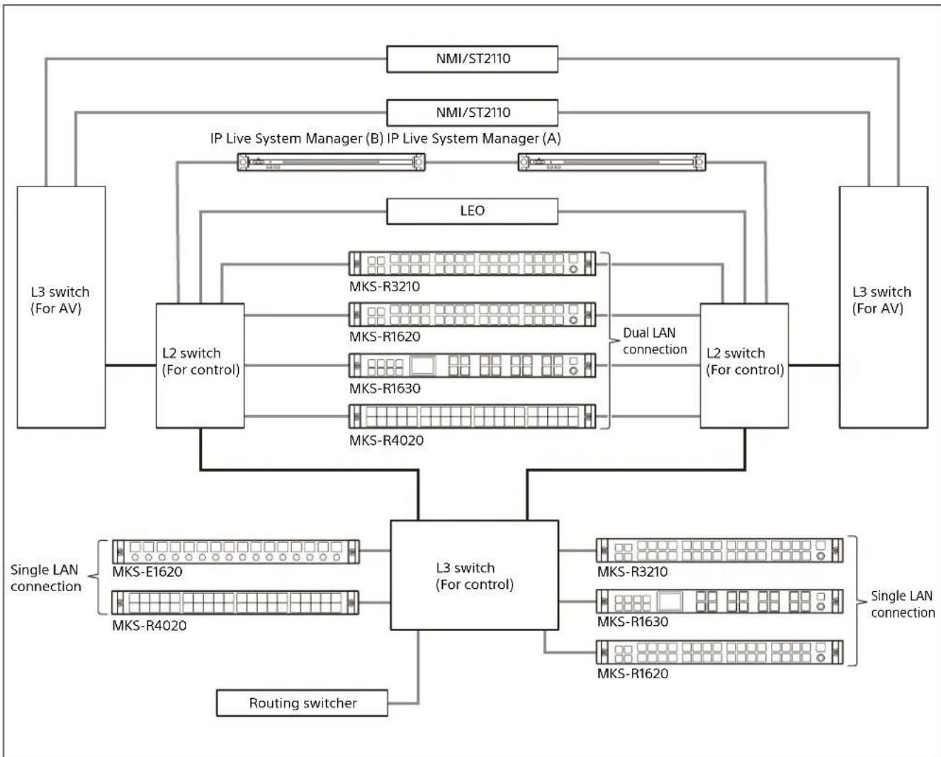
flowchart
graph TD
    A["L3 switch (For AV)"] --> B["L2 switch (For control)"]
    B --> C["L2 switch (For control)"]
    C --> D["L2 switch (For control)"]
    D --> E["L3 switch (For AV)"]
    A --> F["IP Live System Manager (B)"]
    A --> G["IP Live System Manager (A)"]
    A --> H["LEO"]
    H --> I["MKS-R3210"]
    H --> J["MKS-R1620"]
    H --> K["MKS-R1630"]
    H --> L["MKS-R4020"]
    C --> M["Dual LAN connection"]
    D --> N["Single LAN connection"]
    C --> O["L3 switch (For control)"]
    O --> P["MKS-R3210"]
    O --> Q["MKS-R1630"]
    O --> R["MKS-R1620"]
    O --> S["Routing switcher"]
    style A fill:#f9f,stroke:#333
    style E fill:#ccf,stroke:#333
    style F fill:#cfc,stroke:#333
    style G fill:#cfc,stroke:#333
    style H fill:#fcc,stroke:#333
    style I fill:#ffc,stroke:#333
    style J fill:#ffc,stroke:#333
    style K fill:#ffc,stroke:#333
    style L fill:#ffc,stroke:#333
    style M fill:#cfc,stroke:#333
    style N fill:#cfc,stroke:#333
    style O fill:#cfc,stroke:#333
    style P fill:#cfc,stroke:#333
    style Q fill:#cfc,stroke:#333
    style R fill:#cfc,stroke:#333
    style S fill:#cfc,stroke:#333
Locations and Functions of Parts
Front Panel
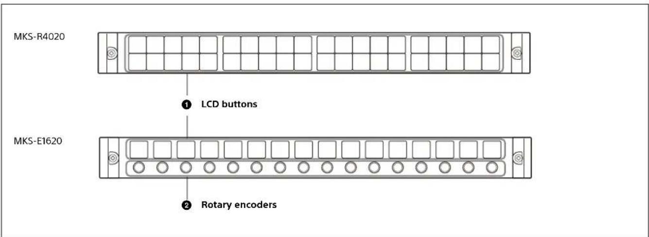
text_image
MKS-R4020 ① LCD buttons MKS-E1620 ② Rotary encoders① LCD buttons
When connected to a system controller, these buttons can be used as source selection buttons, destination selection buttons, or level selection buttons. You can configure the type of selection of the buttons using the web menu or the assignment function.
When connected to LEO, the settings of the LCD buttons are made from LEO.
② Rotary encoders
The function of each encoder is set by LEO.
Rear Panel
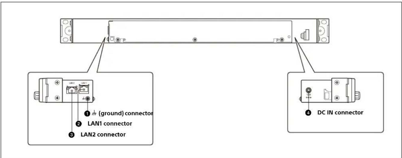
text_image
LAN1 (ground) connector LAN1 connector LAN2 connector DC IN connector① 1m (ground) connector
For signal grounding.
② LAN1 (PoEconnector
Connect to the network on which the system controller or LEO is connected (network 1). This connector accepts power using PoE.
CAUTION for LAN connector
The LAN connector of this unit is to be connected only to the devices whose power feeding meets the requirements for SELV (Safety Extra Low Voltage) and complies with Limited Power Source according to IEC 60950-1.
CAUTION
When you connect the LAN cable of the unit to peripheral device, a shielded-type cable is strongly recommended to prevent malfunction due to radiation noise and electrostatic noise.
③ LAN2 connector
Connect to the network with system controller connected (network 2).
CAUTION for LAN connector
For safety, do not connect the connector for peripheral device wiring that might have excessive voltage to the following port:
• LAN2 connector
Notes
- When you connect the LAN cable of the unit to peripheral device, a shielded-type cable is strongly recommended to prevent malfunction due to radiation noise and electrostatic noise.
- If a redundancy configuration is not used on the network, use the LAN1 connector.
4 DC IN connector
Connect to the supplied AC adapter.
Preparations
Notes on Installation
For installing the unit in a 19-inch rack
When installing in a 19-inch rack, use binding-head screws (+B5×10, 7-682-575-04).
For use in an OB van
When the unit is to be used in an OB van, be sure to bind the cables to a rack strut to avoid having the weight of cables add to vibration shock to the connector on the side panel during transport.
Setting Up the Unit
First, configure the network preferences using the buttons on the unit. For details about network preferences and connection mode settings, refer to the Installation Manual. You can enter the IP address specified for the unit in a web browser to display the web menu. Use the web menu to configure detailed settings.
Connections with System Controllers and LEO
A remote control panel can be connected in a single system connection or in a redundancy system connection. Several modes are supported for redundancy system connections.
Single system connection
A single system connection is the simplest connection type.
Use LAN1.
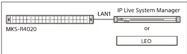
flowchart
graph LR
    A["MKS-R4020"] -->|LAN1| B["IP Live System Manager"]
    B -->|or| C["LEO"]
Dual LAN redundancy system connection
A dual system redundancy structure uses both LAN1 and LAN2 of the remote control panel.
Operation will continue in the event of a single system switch failure.
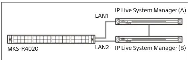
text_image
MKS-R4020 LAN1 IP Live System Manager (A) LAN2 IP Live System Manager (B)Note
When using a dual LAN1 and LAN2 system connection, do not use IP addresses for the same segment.
Single LAN redundancy system connection
A single system redundancy structure uses only LAN1 of the remote control panel. The wiring for LAN1 only is connected, but the panel connects to both system A and system B. This configuration is useful if you want to reduce the LAN cable wiring or if there are no available ports on a switch. Use LAN1.
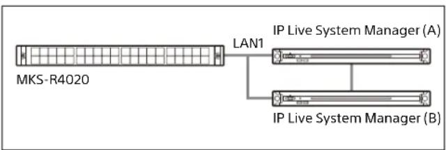
flowchart
graph LR
    A["MKS-R4020"] -->|LAN1| B["IP Live System Manager (A)"]
    A --> C["IP Live System Manager (B)"]
Configuring Using the Buttons
Basic settings of the unit can be configured using the web menu, but the following settings can also be configured directly on the unit. The following items can be set on the unit by turning the power on while pressing a combination of LCD buttons, as described below.
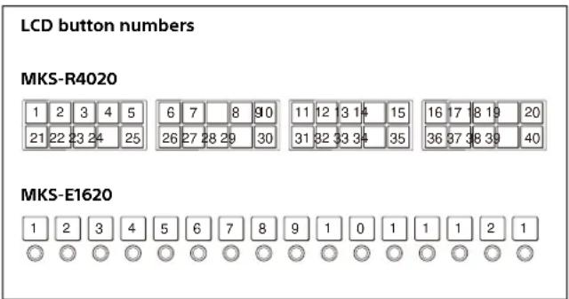
text_image
LCD button numbers MKS-R4020 1 2 3 4 5 6 7 8 90 11 12 3 14 15 16 17 8 19 20 21 22 23 24 25 26 27 28 29 30 31 32 33 34 35 36 37 38 39 40 MKS-E1620 1 2 3 4 5 6 7 8 9 1 0 1 1 1 2 1Setting the default IP address
Simultaneously press buttons 1 and 2, then turn the power on. For details about the IP address setting, refer to the Installation Manual.
Resetting the software
On the MKS-E1620, press and hold buttons 1, 3, and 4 simultaneously for three seconds or longer. On the MKS-R4020, press and hold buttons 21, 23, and 24, for three seconds or longer. The software is reset, and the unit returns to the same status as when power is first turned on.
Operations
Note
This section describes typical operation on the MKS-R4020. For other models, substitute the button names and other items corresponding to your model.
LEO Operation
In LEO operating mode, all the LCD buttons and rotary encoders are configured and controlled from LEO. For details, refer to the User Manual of Live Element Orchestrator.
NS-BUS Operation
On the MKS-R4020, all the LCD buttons can be configured as selection buttons or function buttons. You can assign a crosspoint switching function, or a source or destination to a selection button. You can assign a function that performs an operation to a function button. The required functions to perform operations must be assigned to the function buttons beforehand. For details about button assignment, see "Panel Table Page" (page 15) in the web menu section.
Selection buttons and pinned buttons
The LCD buttons on the MKS-R4020 include pinned buttons with common assignment on all pages and selection buttons for assigning to each page. You can assign a function to a pinned button. You can assign a source, destination, and some functions to selection buttons. For details about assignment, see "Panel Table Page" (page 15) in the web menu section.
Function buttons
Function buttons are pinned buttons and selection buttons to which a function has been assigned.
For details about assignment, see "Panel Table Page" (page 15) in the web menu section.
The following functions can be assigned.
Monitor function: This function can be assigned to any button, and a button assigned with the Monitor function becomes a MONI button. For details about the MONI button, see "Monitoring Destinations" (page 13).
Status function: This function can be assigned to a pinned button only, and a button assigned with the Status function becomes a STATUS button. The STATUS button flashes red when an error occurs.
Protect function: This function can be assigned to any button, and a button assigned with the Protect function becomes a PROT button. For details about the PROT button, see "Preventing Source Switching for Destinations (Protect)" (page 13).
Lock (Chop) function: This function can be assigned to any button, and a button assigned with the Lock (Chop) function becomes a LOCK (CHOP) button. For details about the LOCK (CHOP) button, see "Preventing Accidental Operation (Lock)" (page 13) and "Switching and Monitoring Two Sources (Chop)" (page 12).
Assign function: This function can be assigned to a pinned button only, and a button assigned with the Assign function becomes an ASSGN button. For details about using the ASSGN button, see "Assigning a source/destination to a selection button (Assign)" (page 9).
Source, Destination/Level function: This function can be assigned to any button, and a button assigned with the Source, Destination/Level function becomes a SRC,DEST/LEVEL button. For details about the SRC,DEST/LEVEL button, see "Switching between source selection mode and destination selection mode" (page 8). For details about the Level function, see "Switching the source for each level" (page 10).
Entry function: This function can be assigned to any button, and a button assigned with the Entry function becomes an ENTRY button. For details about the ENTRY button, see "Switching between BPS (button per source) selection method and MD (multi destination) selection method" (page 8).
Page Up/Group Up function, Page Down/Group Down function: These functions can be assigned to any button. A button assigned with the Page Up/Group Up function becomes a PG UP/GP UP button. A button assigned with the Page Down/Group Down function becomes a PG DN/GP DN button. For details about the PG UP/GP UP button and PG DN/GP DN button, see "Pages and Page Groups" (page 12).
Group Up function, Group Down function: These functions can be assigned to any button. A button assigned with the Group Up function becomes a GP UP button. A button assigned with the Group Down function becomes a GP DN button. For details about the GP UP button and GP DN button, see "Pages and Page Groups" (page 12).
Group Jump function: This function can be assigned to any button, and a button assigned with the Group Jump function becomes an GP JUMP button. For details about the GP JUMP button, see "Pages and Page Groups" (page 12).
Take function: This function can be assigned to any button, and a button assigned with the Take function becomes a TAKE button. For details about the TAKE button, see "Take Mode" (page 12).
Level function: This function can be assigned to a pinned button only, and a button assigned with the Level function becomes a LEVEL button. When a LEVEL button is pressed, the specified level becomes active. It is lit green when all specified levels are active. For details about the LEVEL button, see "Level Control" (page 14).
Shift function: This function can be assigned to any button, and a button assigned with the Shift function becomes a SHIFT button. Used for level selection using the SRC,DEST/LEVEL button and when switching groups using the PG UP/GP UP and PG DN/GP DN buttons.
Home function: This function can be assigned to any button, and a button assigned with the Home function becomes a HOME button. When a remote control panel is configured in Hybrid connection mode, pressing this switches to LEO operating mode and returns to the LEO home page.
Back function: This function can be assigned to any button, and a button assigned with the Back function becomes a BACK button. When a remote control panel is configured in Hybrid connection mode, pressing this switches to LEO operating mode and returns to the previous LEO page.
Switching between source selection mode and destination selection mode
You can switch between source selection mode and destination selection mode by pressing the SRC,DEST/LEVEL button.
Note
The SRC,DEST/LEVEL button is required.
Destination selection mode
1 Press the SRC,DEST/LEVEL button so that the SRC,DEST/LEVEL button lights up bright amber.
The names of destinations are displayed on selection buttons assigned with a source/destination or a destination only. The names of sources are displayed on selection buttons assigned with a source only.
Source selection mode
1 Press the SRC,DEST/LEVEL button so that the SRC,DEST/LEVEL button lights up bright green.
The names of sources are displayed on selection buttons assigned with a source/destination or a source only. The display configured on the [Display Settings] page (page 19) of the web menu is displayed on selection buttons assigned with a destination only.
Switching between BPS (button per source) selection method and MD (multi destination) selection method
Crosspoints can be switched using the BPS selection method or MD selection method. For details about switching the selection method, see "Enable Mode" (page 18) in "Operation Settings Page" in the web menu section. You can select BPS Only, MD Only, or BPS/MD. When BPS/MD is selected, you can switch the selection method by pressing the ENTRY button. When BPS Only is selected, you can switch to MD Only, and vice versa.
Switching the control destination
The control destination can be switched at startup, when switching pages, when switching page groups, or when a selection button assigned with a destination is pressed.
At startup or when switching pages
Configure settings as described in "Default Controls Page" (page 18) in the web menu section.
When switching page groups
Configure settings as described in "Page Group Settings Page" (page 21) in the web menu section.
When a selection button is pressed
In the BPS (button per source) selection method in destination selection mode, or in the MD (multi destination) selection method in source selection mode, press a selection button assigned with a destination to make that destination the control destination.
In the BPS (button per source) selection method in source selection mode, press a selection button assigned with a destination only to make that destination the control destination.
Switching crosspoints
The source names and destination names for the selection buttons on the front panel are configured using the web menu. Using these buttons, you can select a source and destination for switching a crosspoint.
Changing the selection method
Set the selection method as described in "Switching between BPS (button per source) selection method and MD (multi destination) selection method" (page 8).
BPS (button per source) selection method
In the BPS selection method, you press destination and source selection buttons on which the corresponding signals have been assigned to switch the crosspoint.
1 Set the control destination as a destination for switching a crosspoint as described in "Switching the control destination" (page 8).
2 Set source selection mode as described in "Switching between source selection mode and destination selection mode" (page 8).
3 Press a selection button assigned with a source to be switched to select the source.
The crosspoint is switched.
Status display of selection buttons
The control destination and the source corresponding to the control destination are lit brightly, while the other selection buttons are lit dimly. For details about setting the display color, see "Display Settings Page" (page 19) in the web menu section.
MD (multi destination) selection method
In the MD selection method, a source and destination are assigned to one selection button. You can switch a crosspoint just by pressing the selection button.
Note
In the MD selection method, both a source and destination must be assigned to a selection button. If a selection button is assigned with only a source or destination, the button operates as in the BPS selection method.
1 Press a selection button.
The crosspoint set on the pressed button is switched.
Status display of selection buttons
The destination and source assigned to selection buttons are lit brightly when connected, and lit dimly when not connected. For details about setting the display color, see "Display Settings Page" (page 19) in the web menu section.
Assigning a source/destination to a selection button (Assign)
You can assign sources and destinations to selection buttons on the [Panel Table] page (page 15) of the web menu. You can also assign sources and destinations from the panel of the unit.
The permissions for assigning sources and destinations from the panel are configured on the [Operation Settings] page (page 18) of the web menu.
Notes
- You cannot assign to a selection button to which a function has been configured. To make an assignment, cancel the function assignment and then assign a source or destination.
- An ASSIGN button, SRC,DEST/LEVEL button, PG UP/GP UP button, PG DN/GP DN button, and STATUS button are required.
Assigning a source to a selection button
1 Set source selection mode as described in "Switching between source selection mode and destination selection mode" (page 8).
2 Press the ASSIGN button.
The STATUS button display is lit bright green, and the source name is displayed in inverted color.
The STATUS button display is lit bright green, and the source name is displayed in inverted color.
3 Press and hold the ASSIGN button, and press the PG UP/GP UP button or PG DN/GP DN button to display the name of the source to set.
4 Press and hold the ASSIGN button, and press the selection button you want to set for the source. The ASSIGN button is lit bright green while it is pressed.
When the ASSIGN button is released, it returns to being lit dim green, and the STATUS button display returns to its state preceding step 2.
Note
When the same source as the source assigned to a selection button is assigned, the source assignment of the selection button is cleared.
Assigning a destination to a selection button
1 Set destination selection mode as described in "Switching between source selection mode and destination selection mode" (page 8).
2 Press the ASSIGN button.
The STATUS button display is lit bright amber, and the destination name is displayed in inverted color.
3 Press and hold the ASSIGN button, and press the PG UP/GP UP button or PG DN/GP DN button to display the name of the destination to set.
4 Press and hold the ASSIGN button, and press the selection button you want to set for the destination. The ASSIGN button is lit bright green while it is pressed.
When the ASSIGN button is released, it returns to being lit dim green, and the STATUS button display returns to its state preceding step 2.
Note
When the same destination as the destination assigned to a selection button is assigned, the destination assignment of the selection button is cleared.
To set a selection button to "No Assign"
When a selection button is set to "No Assignment," the source or destination assignment is cleared.
Notes
- [Enable No Assignment] must be executed on the [Operation Settings] page (page 18) of the web menu. When executed, all source, destination, and function assignments are cleared.
- The assignment of function buttons cannot be set to "No Assign."
1 Press the ASSIGN button.
2 Press and hold the ASSIGN button, and press the selection button you want to set to "No Assign" for 3 seconds.
The assignment is cleared, and the selection button lamp turns off.
The ASSIGN button is lit bright green while it is pressed.
When the ASSIGN button is released, it returns to being lit dim green.
Switching a Different Source for Each Level (Breakaway)
When switching sources, a different source can be switched for each level. This is called the breakaway function.
When the breakaway function is used, the display of the source/destination selection buttons and level selection buttons is different from the basic operation. When IN001 to IN016 are assigned to selection buttons 1 to 16 in the BPS selection method, the display changes as follows.
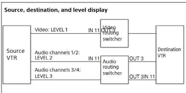
When the breakaway function is not used
The following is displayed when a single source is selected for all levels.
| Level Source Destination |
| LEVEL 1 IN 11 OUT 3 |
| LEVEL 2 IN 11 OUT 3 |
| LEVEL 3 IN 11 OUT 3 |
flowchart
graph LR
    A["Source VTR"] --> B["Video: LEVEL 1 IN 11"]
    A --> C["Audio channels 1/2: LEVEL 2 IN 11"]
    A --> D["Audio channels 3/4: LEVEL 3 IN 11"]
    B --> E["Video routing switcher"]
    C --> F["Audio routing switcher"]
    D --> G["OUT 3 OUT 3IN 11"]
    E --> H["Destination VTR"]
    F --> H
When the breakaway function is used
The following is displayed when different sources are selected for each level.
| Level Source Destination |
| LEVEL 1 IN 11 OUT 3 |
Level Source Destination
LEVEL 2 IN 14 OUT 3
LEVEL 3 IN 16 OUT 3
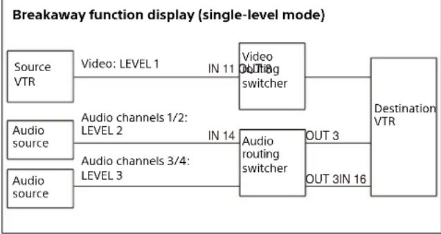
flowchart
graph LR
    A["Source VTR"] -->|Video: LEVEL 1 IN 11| B["Video Outting switcher"]
    C["Audio source"] -->|Audio channels 1/2: LEVEL 2 IN 14| D["Audio routing switcher"]
    E["Audio source"] -->|Audio channels 3/4: LEVEL 3 IN 14| D
    B --> F["Destination VTR"]
    D --> G["OUT 3 OUT 3IN 16"]
Selection button display when the breakaway function is used (BPS selection method)
When a single level is selected, the breakaway function is not used, and the sources with the selected level light up brightly in the color configured using [Display Settings] > [Color Settings] in the web menu. When LEVEL1 is selected, the IN11 display is lit brightly. When LEVEL3 is selected, IN16 is lit brightly.
When multiple levels are selected, the display changes according to the [Display Settings] > [Breakaway] setting in the web menu.
When LEVEL1, LEVEL2, and LEVEL3 are selected and [Breakaway] is set to [Top Level], the LEVEL1 (top level among the selected levels) source IN11 display is lit brightly in the color specified using [Breakaway Color]. When set to [All Level], the LEVEL1 (top level among the selected levels) source IN11 display is lit brightly in the color specified using [Color Settings], and the other sources IN14 and IN16 are lit brightly in the color specified using [Breakaway Color].
Switching the source for each level
Note
A SRC,DEST/LEVEL button and SHIFT button are required.
1 Press the SHIFT button.
2 Press the SRC,DEST/LEVEL button to set level selection mode.
The SRC,DEST/LEVEL button lights up red.
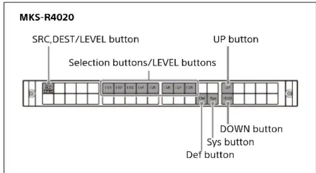
text_image
MKS-R4020 SRC,DEST/LEVEL button UP button Selection buttons/LEVEL buttons DOWN button Sys button Def buttonIn level selection mode, the selection button assignments are changed.
The DEST button is assigned to selection button 1, levels are assigned to selection buttons 6 to 13, and the active level selection button lights up.
The Def button is assigned to selection button 34, the Sys button is assigned to selection button 35, and the UP and DOWN buttons are assigned to selection buttons 16 and 36.
Def button: Enable the levels defined on the [Default Control] page in the web menu.
Sys button: Enable the levels that are enabled on the system controller.
UP/DOWN buttons: Display the previous/next level.
3 Press a selection button to select the level.
There are two selection methods: single mode and multi mode.
In single mode, only one level is selected. Press a selection button to enable that level. All other levels become disabled.
In multi mode, multiple levels can be selected. Press multiple selection buttons. The selected levels are all enabled. Pressing the selection button of an enabled level will disable that level.
You can change the selection method on the [Default Control] page in the web menu.
4 Press the SRC,DEST/LEVEL button to exit level selection mode.
5 Select a source.
6 Repeat from step 1 for other levels.
About levels
In a routing switcher system, multiple signals for one destination can be switched at the same time using the level function. Different kinds of signals, such as 4K video, HD video, audio, etc. are assigned to different levels, and the type of signal to switch is controlled using levels.
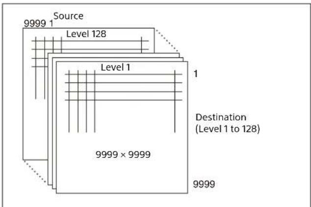
flowchart
graph TD
    A["9999"] --> B["Source"]
    B --> C["Level 128"]
    C --> D["Level 1"]
    D --> E["Destination (Level 1 to 128)"]
    E --> F["9999 × 9999"]
    style A fill:#f9f,stroke:#333
    style B fill:#ccf,stroke:#333
    style C fill:#cfc,stroke:#333
    style D fill:#fcc,stroke:#333
    style E fill:#cff,stroke:#333
    style F fill:#ffc,stroke:#333
Switching Multiple Crosspoints Simultaneously (Salvo)
You can switch multiple crosspoints by pressing a single selection button configured beforehand in the web menu. This is called the salvo function.
The unit supports local salvo and snapshot salvo.
Local salvo
This salvo is managed by the remote control panel. It supports crosspoint switching that is unrelated to the control destination and switching using a destination
offset local salvo. Up to 64 crosspoints can be set for a button.
Snapshot salvo
This salvo is managed by a system controller. It is used to perform salvo switching common to two or more remote panels.
Destination offset local salvo
A destination offset local salvo switches a destination calculated by adding an offset value to the control destination. For example, if the control destination is 0015 and the offset value is 2, the crosspoint for destination 0017 is switched.
The following usage is supported by a destination offset local salvo.
Example 1
To assign a source (audio source 0007, for example) of a level to multiple sources of another level (video sources 0001 and 0005, for example)
| Source for each level Destination offset salvo setting | |||
| Salvo ID | Level 1 Level 2 | Salvo name | Offset Source Level |
| 0001 | 0001 | 0001 | 00007 01000000 |
| 0005 | 0005 | 0005 | 00007 01000000 |
Example 2
To set a pair of crosspoints (multiple audio channels, video key signal, for example)
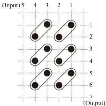
text_image
(Input) 5 4 3 2 1 1 2 3 4 5 6 7 (Output)| Destination offset salvo setting | |||
| Salvo name | Offset | Source | Level |
| IN001 | 0 | 0001 | 10000000 |
| 1 | 0002 | 10000000 | |
| IN003 | 0 | 0003 | 10000000 |
| 1 | 0004 | 10000000 | |
Executing a salvo
1 Set the control destination as the base destination as described in "Switching the control destination" (page 8).
This is not required if the salvo does not include a destination offset local salvo.
2 Assign a salvo to a source in the web menu as described in "Salvo Table Page" (page 16).
3 Assign the source from step 2 to a selection button.
When you press the selection button assigned with the salvo function, all the crosspoints configured in the salvo are switched.
Take Mode
The method for issuing a Take to switch crosspoints can be set to "Immediate," "Preset," or "Preset2" on the [Operation Setting page] (page 18) of the web menu. To set for each page group, configure settings as described in "Page Group Settings Page" (page 21) in the web menu section.
Immediate: Immediate Take mode
In BPS mode, the Take function is executed at the moment the source selection button is pressed. In MD selection mode, the Take function is executed at the moment when the button with the assigned source is pressed.
Preset: Preset Take mode
After a source selection button (BPS selection mode) or button with assigned source (MD selection mode) is pressed, the selected source is stored as the preset source and the button becomes a TAKE button for a few seconds. The Take function is executed when the TAKE button is pressed with the source stored as the preset source.
Preset 2: Preset 2 Take mode
In Preset 2 Take mode, the button does not become a TAKE button. All other actions are the same as for Preset Take mode.
- In Preset Take mode or Preset Take 2 mode, the bottom of the display window of the source selection button with the preset source is displayed highlighted.
- The TAKE button can be assigned to a button as described in "Panel Table Page" (page 15) in the web menu section.
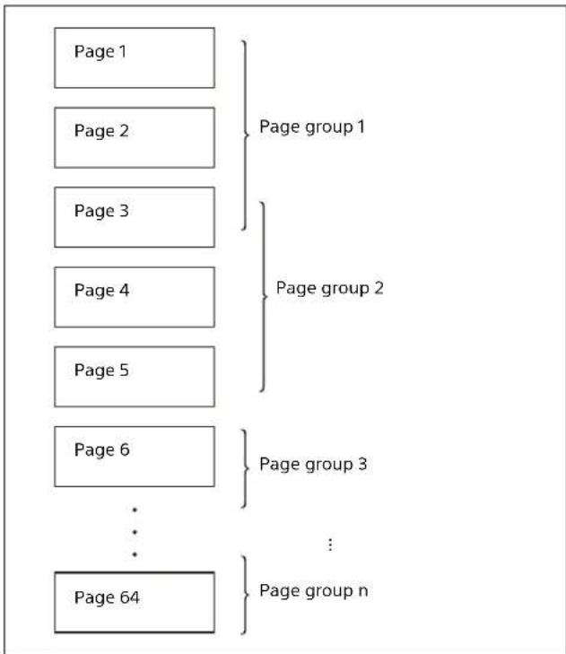
Pages and Page Groups
In the BPS selection method and MD selection method, you can assign multiple functions to selection buttons using the web menu. The unit controls crosspoint switching according to these settings. One set of settings is made per setting page using the web menu, and up to 64 sets (64 pages) of settings can be configured. A page name is assigned to each page.
Consecutive pages can be grouped, and a group name can be assigned to each group. Up to 64 groups can be configured. A single page can also be registered in multiple groups.
The page to be displayed when the unit is turned on can be set using the web menu.
flowchart
graph TD
    A["Page 1"] --> B["Page group 1"]
    C["Page 2"] --> D["Page group 2"]
    E["Page 3"] --> F["Page group 3"]
    G["Page 4"] --> H["..."]
    I["Page 5"] --> J["Page group n"]
    K["Page 6"] --> L["..."]
    M["Page 64"] --> N["..."]
Switching a page or page group
To switch the page, press the PG UP/GP UP or PG DN/GP DN button.
To switch the page group, press the SHIFT button and then press the PG UP/GP UP or PG DN/GP DN button.
Switching the page group can also be performed by pressing the GP UP, GP DN, or GP JUMP button.
The button to use must be assigned beforehand using the web menu.
Switching pages
To display the next page, press the PG UP/GP UP button. To display the previous page, press the PG DN/GP DN button.
The pressed button momentarily lights up bright green, and the page is switched.
Switching page groups
To display the next page group, press the GP UP button, or press the SHIFT button and then the PG UP/GP UP button. To display the previous page group, press the GP DN button, or press the SHIFT button and then the PG DN/GP DN button.
To display a specific page group, press the GP JUMP button configured for that page group.
Switching and Monitoring Two Sources (Chop)
Two sources can be switched alternately at a specified interval automatically. The chop function can also be used when using the salvo function. The source switching interval can be adjusted with the PG UP/GP UP button and PG DN/GP DN button.
Note
The LOCK (CHOP) button is required.
Switching sources
1 Set the control destination as a destination for switching a crosspoint as described in "Switching the control destination" (page 8).
2 Set source selection mode as described in "Switching between source selection mode and destination selection mode" (page 8).
3 Press a selection button to select source 1.
4 Press and hold the LOCK (CHOP) button for three seconds or longer.
The button lights up bright green.
5 Press a selection button to select source 2.
Source 1 and 2 are switched alternately.
The method for selecting a destination or source varies depending on the selection method.
If a selection button for which a salvo has been set is pressed, a salvo chop is executed.
Terminating chop
Press the LOCK (CHOP) button.
Adjusting the chop interval
Press the PG UP/GP UP button to make the switch interval longer, and press the PG DN/GP DN button to make it shorter.
Note
The PG UP/GP UP button and PG DN/GP DN button are required.
Preventing Source Switching for Destinations (Protect)
When protection is set, switching of the source for the protected destination is disabled.
Note
The PROT button is required.
Setting protection
1 Select a destination to be protected.
2 Press the PROT button.
The PROT button lights up green, and protection mode is activated. Switching of the crosspoint for the destination specified in step 1 is disabled.
Releasing protection
Protection can be released only on the unit which the protection was set. Normally, the protection on other units cannot be released.
1 Select a destination whose protection is to be released.
2 Press the PROT button.
The PROT button lamp turns off, and the protection is released.
Protection set on another remote control panel
If you select a destination for which protection has been set on another remote control panel, the pressed button and the PROT button light up red.
Note
When [Protect Mode] is set to [Occupy] in the web menu, switching is possible without releasing the protection, if protection is set, on the currently operating remote control panel (switching is not possible on other remote control panels when protected). Set [Protect Mode] to [Protect] for normal operation.
Preventing Accidental Operation (Lock)
When the panel is locked, accidental switching of crosspoints is avoided.
If you press the STATUS button when a panel is locked, "Locked" and the IP addresses of LAN1 and LAN2 appear alternately on the STATUS button.
Note
The LOCK (CHOP) button is required. The STATUS button is required in order to check the button display.
Locking the panel
1 Press the LOCK (CHOP) button.
The LOCK (CHOP) button lights up red (lock mode). All buttons other than the LOCK (CHOP) button are disabled.
Releasing the lock
1 Press the LOCK (CHOP) button.
The LOCK(CHOP) button lamp turns off, and lock mode is released.
Monitoring Destinations
When you specify a destination to be monitored using IP Live System Manager or the web menu, the control destination automatically selects the same source as the destination you wish to monitor when the MONI button is pressed.
1 Set the destination you want to monitor in [Destination Monitoring] in IP Live System Manager.
2 Set the MONI button configured for the destination you want to monitor in the web menu.
3 Press the MONI button.
The source for the pressed control destination is linked to the source of the destination you want to monitor.
Level Control
You can assign levels to selection buttons, and use them as LEVEL selection buttons.
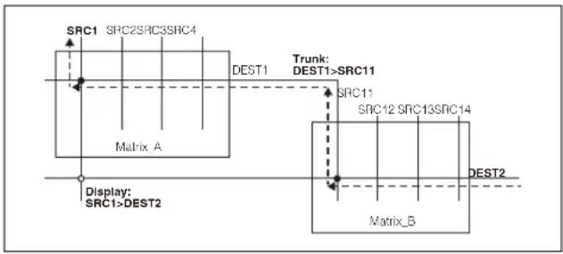
Retrace Function
This function displays the source name of a source by virtually connecting (trunk) crosspoint matrix spaces and retracing the crosspoint status.
- The settings are configured using [Retrace Settings] in the web menu.
- Up to 512 retrace trunks can be configured.
- A retrace can comprise up to five steps.
- When [Display Mode] is set to [Prompt], the retrace function is not available.
- You can check the retrace status by selecting [Available Src/Dest] > [Destination] in the web menu.
flowchart
graph TD
    A["Matrix_A"] --> B["SRCSRC1"]
    A --> C["SRCSRC2"]
    A --> D["SRCSRC3"]
    A --> E["SRCSRC4"]
    F["Matrix_B"] --> G["TRUNK: DEST1 > SRC11"]
    F --> H["TRUNK: DEST1 > SRC11"]
    F --> I["TRUNK: DEST1 > SRC11"]
    J["Display: SRC1 > DEST2"] --> K["Matrix_A"]
    L["DEST2"] --> M["Matrix_B"]
Linkage Function
This function links multiple remote control panels so that they operate as a single control panel.
You can combine remote control panels in a group and link them by setting one panel as the parent panel and the others as child panels.
- On devices that operate together as parent/child, the control destination, control panel, lock state, and preset sources are shared.
- The settings are configured using [Linkage Settings] in the web menu.
- Up to 10 child devices can be configure for a single parent device.
- Linked operation using a mix of MKS-R3210/R1620/R1630/R4020 is supported.
Configuring a child device
1 On the device to set as a child, select the [Child] radio button under [Linkage Settings] in the web menu, and set the IP address of the parent. In systems with network redundancy, set Parent IP Address 1 and 2. On systems without network redundancy, set Parent IP Address 1.
When a child of the parent is authorized, a green "O" mark and "Authorized" are displayed. If not authorized, a gray "O" mark and "Not authorized" are displayed.
If information sharing with the parent is enabled, a green "O" mark and "Shared" are displayed. If information sharing is disabled, a gray "O" mark and "Not shared" are displayed.
Configuring a parent device
1 On the device to set as a parent, select the [Parent] radio button under [Linkage Settings] in the web menu.
2 Information for devices configured as child devices (Name, IP Address1, IP Address2, Authorization, Share, User, Model, Description) is displayed in the list under [Linkage Settings] in the web menu. Check the displayed contents, select the child devices and click the [Authorized] button to authorize the device.
Note
Regardless of the authorization status of the child device, control from the parent device to the child device is possible, but control from an unauthorized child device is not possible.
3 Set [Salvo Table], [Available Src/Dest], [Control Area], and [Default Controls] > [Level Settings] (excluding [Level Mode]) on the parent device in the web menu. Copy the settings to the child devices using the [Copy Config] button under [Linkage Settings] in the web menu.
4 To link pages between parent and child, set [Default Controls] > [Startup Page] and [Destination Settings], [Operation Settings] > [BPS/MD Take Mode], [Preset Mode], [Panel Layout], [Enable Src/ Dest Page Interlock], and [Page Group Settings] on the parent device in the web menu, and set [Linkage Settings] > [Copy Cfg+Page] button on the child device, and enable [Enable Page Link].
Notes
- If there is a mismatch in the above settings on parent and child devices, the intended operations may not be possible.
- If an MKS-R3210 is a parent device, the page link cannot be enabled. If an MKS-R3210 is a child device, the page link function can be enabled but the MKS-R3210 cannot be linked.
Web Menu
Various settings of the unit are configured using the web menu.
Note
Among the menu categories on the MKS-E1620, there are configurable items on the [Display Settings] page (Brightness Level only), [Network Settings] page, [Remote Maintenance] page, [Time Settings] page, and [System] page.
Displaying the Web Menu
Enter the IP address of the unit in a web browser on a computer to display the web menu. https://(IP address of unit)/
The default user name and password are given below.
- User name: admin
- Password: MKSRadmin1 (default password)
You can change the password on the [System] page in the web menu.
The recommended web browser is Google Chrome (for Windows).
When logging in for the first time, the password setup dialog appears. Set a password.
You can check the default IP address by simultaneously pressing buttons 1 and 2, then turning the power on. In NS-BUS operation, you can view the used IP address in the locked state. For details, see "Preventing Accidental Operation (Lock)" (page 13). In LEO operation, it is displayed at startup and when LEO is disconnected.
Screen Configuration
The following buttons are displayed at the top of the web menu screen.
Menu: Displays a list of menu categories.
Info: Displays the system version.
Error: Displays the details for an error when an error occurs.
Search: Searches the list of configuration items and displays the corresponding configuration page.
Reboot: Reboots the unit. Not displayed by default. To display the button, click the [Tools] button and select [Enable power button].
Tools: Contains the following items.
- Refresh: Updates the web menu display with the latest status information.
- Enable power button: Displays the [Reboot] button in the web menu, used for rebooting the unit.
- Switch to LEO Mode: Click to restart in LEO connection mode. Disabled when started in LEO connection mode (MKS-R4020 only).
- Switch to NS-BUS Mode: Click to restart in NS-BUS connection mode. Disabled when started in NS-BUS connection mode (MKS-R4020 only).
- Switch to Hybrid Mode: Click to restart in Hybrid connection mode. Disabled when started in Hybrid connection mode (MKS-R4020 only).
- Download logs: Downloads the logs from the unit.
Note
If you enter the following address in a web browser, maintenance mode enable/disable menu items are added to the Tools menu. https://(IP address of unit)/ns-panel/?maintenance=show
- Enable maintenance mode: Enables maintenance mode for accessing the status of the unit.
- Disable maintenance mode: Switches the unit from maintenance mode back to normal operation mode. Help: Contains the following items.
- Update System: Uploads an updater and updates the system.
- User Manual: Displays the Operating Instructions (PDF).
- About Remote Control Panel Web Menu: Displays information relating to the web menu.
Note
When communication between the browser and remote control panel is disconnected, an error dialog appears. Also, communication between the browser and remote control panel is disconnected when it is displayed at the top right of the web menu screen. Reconnect from the browser.
Panel Table Page
(Not supported on the MKS-E1620.)
Use to assign functions to function buttons and assign connectors to selection buttons.
Setting the layout
1 Select the [Layout] radio button.
2 Double-click the button you want to change in the panel diagram. Alternatively, double-click a row in the list, or select the row and click the [Edit] button. A selection button changes to a pinned button, and a pinned button changes to a selection button.
3 Click the [Save] button.
Setting function buttons
1 Select the [Pinned Button] radio button.
2 Double-click the function button you want to set in the panel diagram. Alternatively, double-click a row in the list, or select the row and click the [Edit] button.
3 Select the function to assign to the button in the dialog.
No Assign: Select to assign no function to the function button.
Monitor: Set the Monitor function.
Status: Set the Status function.
Protect: Set the Protect function.
Lock(Chop): Set the Lock(Chop) function.
Assign: Set the Assign function.
Source, Destination/Level: Set the Source, Destination/Level function.
Entry: Set the Entry function.
Take: Set the Take function.
Page Up/Group Up: Set the Page Up/Group Up function.
Page Down/Group Down: Set the Page Down/Group Down function.
Group Up: Set the Group Up function.
Group Down: Set the Group Down function.
Group Jump: Set the Group Jump function. Set the name to display on the GP JUMP button and page group number of the connection destination.
Shift: Set the Shift function.
Home: Set the Home function.
Back: Set the Back function.
For details about each function, see "Function buttons" (page 7) in "NS-BUS Operation" in the "Operation" section.
4 Click the [Apply] button.
5 Repeat steps 2 to 4 until finished the configuration.
6 Click the [Save] button.
Setting selection buttons
1 Select the [Select Button] radio button.
2 Select the page number you want to set, and specify a page name as required.
3 Double-click the selection button you want to set in the panel diagram. Alternatively, double-click a row in the list, or select the row and click the [Edit] button.
4 Set the function to assign to the button in the dialog.
No Assign: Select to assign no function to the button.
Xpt: Set the source number to assign to a source and the destination number to assign to a destination. You can set either or both. When [Color Settings] is set to [Button] on the [Display Settings] page, you can set separate colors for sources and destinations.
Monitor: Set the destination monitor function for the selection button. Specify the destination number to monitor in the dialog. Setting the destination monitor function monitors the selection information for that destination and automatically selects the same source as that destination.
Level: Assign a level to a selection button to use as a LEVEL selection button. Enter a level name, and place a check mark beside the level to assign to the selection button.
Group Jump: Set the Group Jump function. Set the name to display on the GP JUMP button and page group number of the connection destination.
Protect: Set the Protect function.
Lock (Chop): Set the Lock (Chop) function.
Source, Destination/Level: Set the Source, Destination/Level function.
Entry: Set the Entry function.
Take: Set the Take function.
Page Up/Group Up: Set the Page Up/Group Up function.
Page Down/Group Down: Set the Page Down/Group Down function.
Group Up: Set the Group Up function.
Group Down: Set the Group Down function.
Shift: Set the Shift function.
Home: Set the Home function.
Back: Set the Back function.
5 Click the [Apply] button.
6 Repeat steps 3 to 5 until finished the configuration.
7 Click the [Save] button.
Source Reentry Lists Page
(Not supported on the MKS-E1620.)
Use to associate the monitor target destination of the destination monitor function with a source in the reentry table. Configuring a reentry table allows you to execute the destination monitor function when a source selection button is pressed. You can specify up to 128 reentry tables.
Note
This setting is not required when [Destination Monitoring] is configured in IP Live System Manager v2.3.0 and later.
1 Double-click an ID to set, or select the ID and click the [Edit] button.
2 Enter a source number and destination number in the dialog.
Source Port Number: Enter a source number to associate with the monitor target destination. Monitor Target Number: Enter the monitor target destination number of the destination monitor.
3 Click the [Apply] button.
Salvo Table Page
(Not supported on the MKS-E1620.)
Use to configure a salvo for switching multiple crosspoints at the same time.
A salvo can be a snapshot salvo in which switching crosspoint settings are registered in a system controller, or a local salvo where settings are registered in the remote control panel.
Setting a snapshot salvo
1 Double-click an ID to set in [Salvo Table], or select the ID and click the [Edit] button.
2 Set [Mode] to [Snapshot] in the dialog.
3 Enter [Snapshot ID] and [Assigned Source] settings.
4 Click the [Apply] button.
Setting a local salvo
1 Double-click an ID to set in [Salvo Table], or select the ID and click the [Edit] button.
2 Set [Mode] to [Local] in the dialog.
3 Enter [Name] and [Assigned Source] settings.
4 Click the [Apply] button.
Add the crosspoints to be switched to a local salvo.
1 Click the [+] button in [Xpt Table].
2 To directly specify a destination to switch, select [Destination] in the [Mode] dialog and set a destination. To specify the destination to switch using a control destination offset, select [Offset] and specify an offset value.
3 Set the source to switch.
4 Set the level for issuing the switch command.
5 Set [Delay Cnt].
[Delay Cnt] is the execution delay time in 10 msec units. When a value of 1 or higher is set, the specified crosspoint switch command is issued after the specified time has elapsed when a button is pressed.
6 Click the [Apply] button.
Available Src/Dest Page
(Not supported on the MKS-E1620.)
Use to set the range of sources/destinations available for selection on the unit.
Adding a selectable source/destination
1 Click the [+] button for [Available Source] or [Available Destination].
2 Specify the range of sources or destinations to enable in the dialog.
To specify a single source/destination, enter a value in either [From] or [To].
3 Click the [Apply] button.
The specified source/destination is added to the list in [Available Source] or [Available Destination].
The sources/destinations displayed in these lists are available for selection from the unit.
4 Repeat steps 1 to 3 until finished the configuration.
5 Click the [Save] button.
Deleting a source/destination
1 Select a row to delete in [Available Source] or [Available Destination].
2 Click the [-] button.
3 Repeat steps 1 and 2 until finished the configuration.
4 Click the [Save] button.
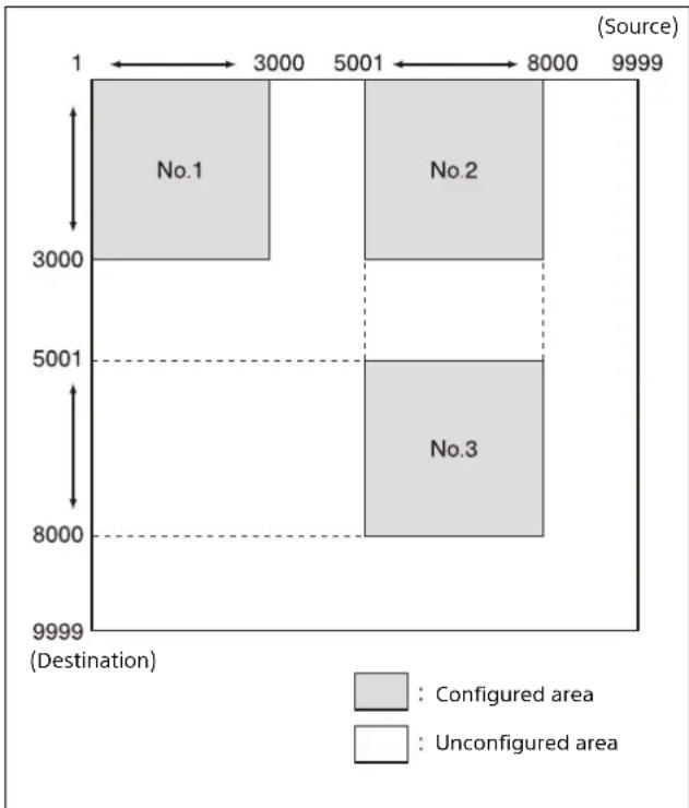
Control Area Page
(Not supported on the MKS-E1620.)
Use to set the range of sources available for selection for the specified destination.
Example settings
| No. Source range Destination range | |
| 1 0001 to 3000 0001 to 3000 | |
| 2 5001 to 8000 0001 to 3000 | |
| 3 5001 to 8000 5001 to 8000 | |
The selectable range for the above settings is shown below.
bar_stacked
| Location | Configured area | Unconfigured area | | -------- | --------------- | ----------------- | | No.1 | 3000 | 0 | | No.2 | 3000 | 0 | | No.3 | 8000 | 0 |When a destination outside the range limit is selected, sources 1 to 9999 are available for selection. In this example, sources 0001 to 9999 are available for selection for destination 3001.
The sources in the range containing the selected destination are all enabled. In this example, sources 0001 to 3000 and 5001 to 8000 are available for selection for destination 0001.
Adding a range
1 Click the [+] button.
2 Enter a source range and destination range in the dialog.
3 Click the [Apply] button.
The specified settings are displayed in the list. Selecting a row in the list displays a blue rectangle covering the range available for selection.
Alias Name Lists Page
(Not supported on the MKS-E1620.)
Displays alias names sent from the system controller.
Select [Source] or [Destination] to display the list of alias names for sources or destinations, respectively.
Default Controls Page
(Not supported on the MKS-E1620.)
Use to set the operation levels and default destination of the unit.
Default Page
Startup Page
Set the page to display after power is turned on.
Note
Set the pages to included in the page group to use on the [Page Group Settings] page.
Destination Settings
Control Destination
Specify the default control destination at startup.
Enable set control destination by page
If you configure a destination for each page and then switch pages, this enables the function to change the control destination to the configured destination for that page.
Level Settings
Level Mode
Select level selection mode.
Single: Only one level can be selected. When a selection button is pressed, only that level is enabled, and other selected levels are deselected.
Multi: Multiple levels can be selected. The levels for a pressed selection button are all selected. When a selected button is pressed, the levels of that button are deselected.
Use Level Type
Select the levels to use in the unit.
System: Use the levels specified by the system controller.
Local: Place a check mark in levels to set the levels used by [Control Level].
Operation Settings Page
(Not supported on the MKS-E1620.)
Use to configure settings relating to the operation of the remote control panel.
Mode Settings
Protect Mode
Set the operation mode when protection is applied. The PROT lamp action is the same when either mode is selected.
Protect: Crosspoint switching is disabled when protection is applied.
Occupy: Crosspoint switching of protected remote control panels only is enabled when protection is applied.
Salvo Protect
This selects the operation if salvo switching is executed while destinations are protected.
Partial Protect: Switch only unprotected destinations.
Full Protect: Do not perform salvo switching if any one of the destinations is protected. Select this mode if a problem would occur if any one location does not switch.
Button Link: Do not perform salvo switching if the PROT lamp on the panel is lit.
Note
When [Protect Mode] is set to [Occupy] in the web menu to enable local protection, salvo switching is not restricted by the [Salvo Protect] setting.
BPS/MD Take Mode
Select the Take operation for the BPS selection method and MD selection method.
Immediate: Use Immediate Take mode
Preset: Use Preset Take mode
Preset 2: Use Preset 2 Take mode
Preset Mode
After executing a crosspoint switch operation (Take function) using normal button operation, set the source to be set as the preset source.
Status: Set the source to switch.
Previous: Set the source that was selected by the control destination immediately before execution.
Enable Chop
Enable the chop function.
Enable Source Assignment
Enable assignment of sources to selection buttons on the panel using the [Assign] button.
Enable Destination Assignment
Enable assignment of destinations to selection buttons on the panel using the [Assign] button.
Enable No Assignment
Clear the assignment of all selection buttons on the panel using the [Assign] button.
Enable Mode
Select the source/destination selection method.
BPS Only: Use the BPS (Button Per Source) selection method only.
MD Only: Use the MD (Multi Destination) selection method only
BPS/MD: Use both the BPS selection method and MD selection method.
Default Panel Layout
Select the selection method to use after power is turned on when [Enable Mode] is set to [BPS/MD].
BPS: Use the BPS selection method.
MD: Use the MD selection method.
Enable Circular (Start ↔ End) Page Select
Enable looping between the start page and end page when switching selection button pages using the PG UP button or PG DN button, and between top level and bottom level when switching levels using the Up/Down buttons in level selection mode.
Enable Circular (Start ↔ End) Page Group Select
Enable looping between the start page group and end page group when switching selection button page groups using the GP UP button or GP DN button.
Enable Rotary Push Switch
Not supported on the MKS-R4020.
Enable Circular (Start ↔ End) Src/Dest Port Select
Enable looping between the start selection option and end selection option when selecting a source/destination using the [Assign] button.
Enable Src/Dest Page Interlock
When enabled, the selection button display page is common to both source selection mode and destination selection mode. When disabled, the display pages are separate in source selection mode and destination selection mode.
Skip Empty Page When Page Up/Down
This setting is enabled when [Enable Src/Dest Page Interlock] is disabled.
When switching pages, skip a page in source selection mode if there it has no button assigned with a source, and skip a page in destination selection mode if it has no button assigned with a destination.
Display Settings Page
(On the MKS-E1620, only Brightness Level is available.) Use to configure settings relating to the display of the remote control panel.
Display Settings
Display Mode
Select the operation mode of the selection buttons when they are lit.
STATUS: Status display mode. Turn on the button for the currently selected source based on the latest crosspoint information. This mode is useful for reflecting the latest status in the button lamps when switching from another panel.
PROMPT: Immediate lighting mode. Pressed buttons light up immediately independently of the crosspoint information.
PROMPT & STATUS: Pressed buttons light up immediately independently of the crosspoint information. Five seconds after the last button operation, the button for the currently selected source lights up based on the latest crosspoint information.
Color Settings
Set the color of selection buttons.
Button: Use color specified for the remote control panel. For details about the color setting, see "Panel Table Page" (page 15) in the web menu section.
Local: Use the standard colors of the remote control panel (source: green, destination: amber).
System: Use the colors specified by the system controller.
Sub LCD Color
Not supported on the MKS-R4020.
Font Size
Set the font size.
Auto: Set to [L Size] to display up to 8 normal-width characters, or to [M Size] to display more characters. Fixed: Displays text in M Size (fixed).
Short Format
Use to set the method for omitting characters when the name of a button is truncated.
From First: Truncate trailing characters that cannot be displayed, displaying the start of the character string.
First+Last: Truncate mid characters, displaying the start and end of the character string.
Brightness Level
Set the brightness of the operation buttons using 3 gradations: 1 (dark) to 3 (bright). Select the brightness according to the operating environment.
Brightness Level (Status Display)
Not supported on the MKS-R4020.
Destination Key Display Mode
Changes the display of operation buttons for which only a destination is configured.
Destination Name: Displays the name of the destination, regardless of the current source/destination selection mode state.
XPT Source Name: Display the crosspoint status (source name) in source selection mode, and displays the destination name in destination selection mode.
- “...” is displayed when a crosspoint is not connected.
- Displays the topmost level in level breakaway state.
- Displays the source with the lowest number if multiple sources exist.
Both(2-Line Display): In source selection mode, display the source name/destination name on two lines. In destination selection mode, display the destination name. The source/destination display position is determined by the [Destination Position in Status Display] setting. The inverted display position is determined by the [Invert Display Position] setting.
Invert Display Position
When [Both(2-Line Display)] is selected in [Destination Key Display Mode] to display the source name and destination name on two lines on a selection button, this sets which line is displayed in inverted color.
Top: Invert the top line.
Bottom: Invert the bottom line.
Dest Position (Status & Dest Key)
When [Both(2-Line Display)] is selected in [Destination Key Display Mode] to display the source name and destination name on two lines on a selection button, this sets which line displays the destination.
Also, when displaying the source name and destination name on two lines, this sets which line displays the destination.
Top: Display the destination on the top line.
Bottom: Display the destination on the bottom line.
Breakaway
Breakaway Display Mode
Top Level: Display the crosspoints of the top level only. All Level: Display the crosspoints of all levels.
Breakaway Color
Set the color of buttons when a different source is selected for each level.
Same as Color Settings: Display the color configured using [Color Settings] in [Display Settings].
1: Displays white.
2: Displays amber.
3: Displays yellow.
4: Displays green.
5: Displays purple.
6: Displays light blue.
7: Displays dark blue.
8: Displays pink.
Alias Priority
Main LCD
Display Priority #1 to #8
Not supported on the MKS-R4020.
Sub LCD
Display Priority
Select the base name or alias name for the connector names to display on the STATUS button.
BASE: Display the base name.
1 to 8: Display the Alias1 to Alias8 name.
2-Line Display
Display Priority
Select the base name or alias name for the connector names to display on the selection button for 2-line display. BASE: Display the base name.
1 to 8: Display the Alias1 to Alias8 name.
Retrace Settings Page
(Not supported on the MKS-E1620.)
Use to configure the function for retracing the crosspoint status display and to display the source names of sources.
1 Enter data in the [Retrace Settings] table.
2 Press the [+] icon in [Retrace Settings] to open the [Retrace] dialog.
3 Enter the destination and source combination and levels to retrace.
4 Press [Apply] to save the settings. To cancel the registration, press [Cancel].
Linkage Settings Page
(Not supported on the MKS-E1620.)
Use to configure the panel link function to link multiple remote control panels.
You can combine remote control panels in a group and link them by setting one panel as the parent panel and the others as child panels.
Stand Alone
Select to use a remote control panel in standalone mode.
Child
Select to use a remote control panel as a child panel using the panel link function.
Authorized: Displays the authorization state from the parent. "O" is displayed in green when authorized ("Not authorized" is displayed when not authorized).
Shared: Displays the status of data sharing with the parent. Displayed in green when data is shared successfully ("Not shared" is displayed when data is not shared).
- Parent IP Address 1: Set the IP ad dress of the LAN1 side on the parent device. "O" is displayed in green on the right when communication is established with the parent on LAN1.
- Parent IP Address 2: Set the IP address of the LAN2 side on the parent device. "O" is displayed in green on the right when communication is established with the parent on LAN2.
Note
Parent IP Address 1 and 2 are settings for a redundancy configuration. Specify different IP addresses for the same parent device.
Parent
Select the remote control panel to use as the parent when using the panel link function. The name, IP address, and other information of the remote control panels that can be configured as the parent device are displayed in a list.
Enable Page Link
Enable page link to always show the same page between parent and child.
Copy Config button
Copy the settings required by the panel link function to a child selected in the list.
The Salvo Table, Available Src/Dest, and Control Area items must be copied. Copy these settings to each child device after configuring them on the parent device.
Copy Cfg+Page button
Copy the settings required for page link by the panel link function to a child device selected in the list. The items that are copied comprise [Default Controls], [Operation Settings] > [BPS/MD Take Mode], [Preset Mode], [Panel Layout], [Enable Src/Dest Page Interlock], and [Page Group Settings] in the web menu. Copy these settings to each child device after configuring them on the parent device.
Verify Config button
Verify that the settings required by the panel link function were copied to a child device selected in the list. The results are displayed in [Config] and [Page].
Authorized button
Authorize the device selected in the list as a child device. Authorize a child device to enable the panel link function.
Note
Regardless of the authorization status of the child device, control from the parent device to the child device is possible, but control from an unauthorized child device is not possible.
Deauthorized button
Deauthorize the child device selected in the list.
Page Group Settings Page
(Not supported on the MKS-E1620.)
Use to register consecutive pages on the [Panel Table] page as a page group.
Setting a page group
1 Double-click a group number to set, or select a row and click the [Edit] button.
2 Specify the group name in the dialog. Place a check mark in [Enable Group] for the page group to use.
3 Specify the pages to include in the page group in [Use Pages].
4 Specify the first page within the page group to display after switching to the page group in [Top Page]. To display the same page when returning to a page group as the page displayed when leaving the page group, set [First Page] to [HOLD].
5 Specify the destination to use in the page group to set in [Control Dest]. To switch the control destination to a specified destination after switching to the page group, enable [Set control destination by group]. To switch the source of the specified destination to the same source when returning to a page group as the source connected when leaving the page group, enable [Back XPT of control destination by group].
6 To execute [Salvo] automatically when switching to the page group to set, enable [Execute Salvo] and set the salvo ID you want to execute.
7 Specify the Take mode in the page group to set. [Local] uses the [Operation Settings] settings. Otherwise, the specified mode is used. For details, see "Take Mode" (page 12).
8 Specify [BPS/MD] in the page group to set. [Local] uses the [Operation Settings] settings. Otherwise, the specified mode is used. For details, see "Switching between BPS (button per source) selection method and MD (multi destination) selection method" (page 8).
9 To change the initial value of LEVEL after switching to the page group to set, enable [Set group level to current level] and specify [Level].
10 Specify the color of the GP JUMP button in [Button Color], and specify the lighting method of the GP JUMP button in [Button Tally].
STATUS: Lit brightly while switching to the specified page group, and lit dimly when not switching.
HIGH: Always lit brightly
LOW: Always lit dimly.
Note
Not lit when [Enable Group] is disabled.
11 Click the [Apply] button.
Network Settings Page
Use to configure settings related to the network.
LAN Settings
Enable Redundancy
Select to enable redundancy using LAN1 and LAN2. If a redundancy configuration is not used, use the LAN1 connector.
Automatic IP address assignment (DHCP) - Using both LAN1 and LAN2
Automatically obtain IP addresses of the remote control panel, system controller, and NTP server. When a check mark is placed in [Enable Redundancy], redundancy dual LAN connection is used.
Note
Cannot be selected in LEO connection mode or Hybrid connection mode.
Manual IP address assignment (Static IP) - Using both LAN1 and LAN2
Set the IP address manually.
When a check mark is placed in [Enable Redundancy], set [LAN1] and [LAN2]. The connection becomes a redundancy dual LAN connection.
When there is no check mark, set [LAN1]. The connection becomes a single system connection.
Manual IP address assignment (Static IP) - Using only LAN1
Set the IP address manually.
When a check mark is placed in [Enable Redundancy], set [LAN1] and the IP address of the redundancy connection destination. The connection becomes a redundancy single LAN connection.
When there is no check mark, set [LAN1]. The connection becomes a single system connection.
LAN1, LAN2
Configure network settings for LAN1 and LAN2.
IP address: IP address
Subnet mask: Subnet mask
Default gateway: Default gateway
System Controller: IP address of system controller (not available on the MKS-E1620)
Ntp Server: IP address of NTP server
LEO: IP address of LEO
System Controller Protocol
Select to use the TCP protocol or TLS protocol for communication with the system controller.
LEO Protocol
Select to use the TCP protocol or TLS protocol for communication with LEO.
Note
The [LAN Settings] configuration is applied when the [Apply] button is clicked.
Remote Maintenance Page
Use to configure settings related to SNMP.
SNMP Settings
Enable SNMPv1
Place a check mark in the checkbox to use SNMP v1.
Enable SNMPv2c
Place a check mark in the checkbox to use SNMP v2c.
Common
Contact Information: Enter contact information for the administrator.
System Name: Enter the name for management.
System Location: Enter location information for management.
SNMPv1/SNMPv2c
Community Name (Read Only): Set the community name for retrieving read-only information.
Allowed Host: Configure settings for hosts with permission to connect.
- NONE: Block access from all IP addresses.
- Specified: Allow access from specific IP addresses.
- ANY: Allow access from all IP addresses.
Allowed Host1: Set the IP address with permission to connect when [Allowed Host] is set to [Specific].
LAN1, LAN2: Select the LAN to use by the host specified in [Allowed Host1].
Allowed Host2: Set the IP address with permission to connect when [Allowed Host] is set to [Specific].
LAN1, LAN2: Select the LAN to use by the host specified in [Allowed Host2].
TRAP
Enable Trap: Place a check mark in the checkbox to enable sending of traps.
Community Name (trap): Set the community name used when sending traps.
Send Authentication trap: Place a check mark in the checkbox to send authentication traps.
SNMP Trap: Specify the destination host for sending traps.
SNMP Version: Select [v1] or [v2c] as the SNMP trap version.
NIC: Select [LAN1] or [LAN2] for the LAN on which to send traps.
Target IP Address: Specify the IP address of the host to which to send traps.
Syslog Settings
Enable SYSLOG
Place a check mark in the checkbox to use Syslog.
LAN1 IP Address
Specify the IP address of the Syslog server connection from LAN1.
LAN2 IP Address
Specify the IP address of the Syslog server connection from LAN2.
Note
If a check mark is not placed in [Enable Redundancy] on the [Network Settings] page, logs are not sent from LAN2.
Severity
Specify the Syslog severity level.
Note
Logs with the specified severity level and higher importance levels will be sent.
Time Settings Page
Use to configure settings related to the date and time.
Time Zone Settings
Time Zone
Set the time zone.
Date and Time Settings
Set time automatically
Automatically set the time using an NTP server. Configure the NTP server settings on the [Network Settings] page. After communication with the NTP server is terminated, the communication result with the server is displayed. If successful, [x] is displayed. If unsuccessful, [-] is displayed.
Time setting
Use to set the date and time manually.
Note
- The [Date and Time Settings] con figuration is applied when the [Apply] button is clicked.
- If the time is not set correctly on the unit, the communication with the system controller or a web browser may not be performed correctly.
System Page
Use to configure settings related to the system.
Error Settings
Enable DC In Error
Enable output of DC IN power supply errors.
System Settings
Name: Enter the name of the remote control panel.
User: Enter the user name of the remote control panel.
Description: Enter a description of the remote control panel.
Password Settings
Use to change the password for the admin user for accessing the web menu.
Old Password: Enter the old password.
New Password: Enter the new password.
Verify: Enter the new password again.
Click the [Change] button to update the password.
Notes
- The password "MKSRadmin1" is configured by factory default.
- The user name (admin) cannot be changed.
- The password is reset to the factory default when the software is reset using [Reset all settings].
- The [Name], [User], and [Description] settings are applied when changes are confirmed.
Save the user settings status.
Save: Save the current settings status to the backup region with a new name.
Restore: Restore the specified settings status saved in the backup region.
Export/Import settings
Export: Download the current settings status as a binary file.
Import: Upload a configuration file from a web browser.
Reset all settings
Restore all menu settings to their default state.
Notes
- Changed passwords are restored to the default state, and the password setup dialog will be displayed the next time you log in.
- The network settings of the remote control panel are also reset.
CSV
Importing and exporting of the following CSV files is supported in [Panel Table], [Salvo Table], [Page Group Settings], [Retrace Settings], and [Source Reentry Lists]. The supported character code set is UTF-8.
The delimiter character is a comma (,).
If data includes a comma, the data must be enclosed by double quotation characters (").
Example: abc,d → "abc,d"
If data includes a double quotation character ("), the data must be enclosed by double quotation characters (") and the characters escaped with another double quotation character (").
Example: a"b"c → "a""b""c"
Source Reentry List CSV format
Syntax
Description
ID: 1 to 128
SrcNum: 1 to 9999 (source number)
TargetDest: 1 to 9999 (target destination to monitor)
Retrace Settings CSV format
Syntax
Description
No: 1 to 512
SrcNum: 1 to 9999 (source number)
DestNum: 1 to 9999 (destination number)
LevelList: 'SYSTEM' or level list (such as "1 2 3 4")
PageGroup CSV format
Syntax
Description
ID: Number
EnableGp: 'ENABLE' or empty (")
GpName: Page group name
UsePages: Page list (such as "1 2 3 4")
TopPage: Page included in the page list
FirstPage: 'HOLD' or 'TOP'
DestNum: 1 to 9999 (destination number)
SetDestByGp: 'SET' or empty (")
BackXPT: 'BACK' or empty (")
Salvo: Salvo ID of 1 to 512 to execute a salvo, or empty (") to not execute a salvo.
Take: 'LOCAL', 'IMMEDIATE', 'PRESET', 'PRESET2'
Layout: 'LOCAL', 'BPS', 'MD'
Tally: 'STATUS', 'HIGH', 'LOW'
Color: 1 to 9 (color number)
LevelList: Level list (such as "1 2 3 4") to change level, or empty (") to not change level
Salvo XPT CSV format
Syntax (DEST)
DEST,
Syntax (OFFSET)
OFFSET,
Description
DestNum: 1 to 9999 (destination number)
OffsetNum: 1 to 9999 (offset value)
SrcNum: 1 to 9999 (source number)
LevelList: 'SYSTEM', empty ("), or level list (such as "1 2 3 4")
DelayCount: 0 to 200 (Delay value)
SalvoTable CSV format
Syntax (Snapshot SALVO)
SALVO,
Syntax (Local SALVO)
SALVO,
Syntax (DEST using salvo XPT of Local SALVO)
XPT,
Syntax (OFFSET using salvo XPT of Local SALVO)
XPT,
Description
SalvoNum: 1 to 512 (Salvo ID)
SalvoName: [Salvo] name (Local Salvo only)
SnapShotId: 1 to 4096 (system controller snapshot ID)
SrcNum: 1 to 9999 (source number)
DestNum: 1 to 9999 (destination number)
OffsetNum: 1 to 9999 (offset value)
SrcNum: 1 to 9999 (source number)
LevelList: 'SYSTEM', empty (''), or level list (such as "1 2 3 4")
DelayCount: 0 to 200 (Delay value)
Panel Table CSV format
Syntax (page name)
NAME,
Syntax (button layout, MKS-R4020 only)
LAYOUT,
Syntax (pinned button assignment)
PINNED,
PINNED,
Syntax (selection button assignment)
Syntax (FUNC-FORMAT)
MONI,
LEVEL_SEL,
GPJUMP,
Description
PageNum: 1 to 64 (page number)
KeyNum: 1 to 40 (button number, maximum value varies depending on the model)
ButtonType: 'PINNED' or empty (")
SrcNum: 1 to 9999 (source number)
DestNum: 1 to 9999 (destination number)
SrcColorNum: 1 to 9 (color number)
DestColorNum: 1 to 9 (color number)
FuncName: 'STAT', 'PROT', 'LOCK_CHOP', 'ASSGN', 'SRC_DEST_LV', 'PGUP_GPUP', 'PGDN_GPDN', 'GPDN', 'GPUP', 'GPDN'
ButtonName: Button name
GroupName: Page group name
LevelList: 'SYSTEM', empty (''), or level list (such as "1 2 3 4")
Usage Precautions
On condensation
If the unit is suddenly taken from a cold to a warm location, or if ambient temperature suddenly rises, moisture may form on the outer surface of the unit and/or inside of the unit. This is known as condensation. If condensation occurs, turn off the unit and wait until the condensation clears before operating the unit. Operating the unit while condensation is present may damage the unit.
About the LCD panels
The LCD panel fitted to this unit is manufactured with high precision technology, giving a functioning pixel ratio of at least 99.99%. Thus a very small proportion of pixels may be "stuck", either always off (black), always on (red, green, or blue), or flashing. In addition, over a long period of use, because of the physical characteristics of the liquid crystal display, such "stuck" pixels may appear spontaneously. These problems are not a malfunction.
About the life expectancy of parts
The life expectancy of the AC adapter and the electrolytic capacitor is about 5 years under normal operating temperatures and normal usage (8 hours per day; 25 days per month).
If usage exceeds the above normal usage frequency, the life expectancy may be reduced correspondingly.
About network security
SONY WILL NOT BE LIABLE FOR DAMAGES OF ANY KIND RESULTING FROM A FAILURE TO IMPLEMENT PROPER SECURITY MEASURES ON TRANSMISSION DEVICES, UNAVOIDABLE DATA LEAKS RESULTING FROM TRANSMISSION SPECIFICATIONS, OR SECURITY PROBLEMS OF ANY KIND.
Depending on the operating environment, unauthorized third parties on the network may be able to access the unit. When connecting the unit to the network, be sure to confirm that the network is protected securely.
From a safety standpoint, when using the unit connected with the network, it is strongly recommended to access the Control window via a Web browser and change the access limitation settings from the factory preset values (page 23).
It is recommended that you set a password with a sufficiently long character string that is hard to guess by others, and that you store it safely.
Do not browse any other website in the Web browser while making settings or after making settings. Since the login status remains in the Web browser, close the Web browser when you complete the settings to prevent unauthorized third parties from using the unit or harmful programs from running.
Error/Warning Messages
If trouble occurs on the unit, the status lamp lights in red and an error/warning message is displayed on the STATUS button.
Warning messages disappear after being displayed for about 2 seconds.
Error messages
| Message Description Solution | ||
| PIF FPGA Err | The PIF FPGA is not operating. | Check the hardware. |
| PIF DDR Err | The PIF DDR SDRAM is not operating. | Check the hardware. |
| KY FPGA Err The KY FPGA | s not operating. Check the hardware. | |
| PIF Recovery | The PIF FPGA started in recovery mode. | Check the hardware. |
| High Temper | The temperature exceeds the rated range. | Check the installation environment. |
| KY Recovery | The KY FPGA started in recovery mode. | Check the hardware. |
| KY Unknown | The KY board model name is unknown. | Check the hardware. |
| SW Recovery | The software started in recovery mode. | Check the hardware. |
| Network Linkdown | Non-redundancy mode: The LAN1 link is down.Redundancy mode: The LAN1/LAN2 links are down. | Check the network settings and connections. |
| DHCP Srv Lost | Non-redundancy mode: The lease file of LAN1 does not exist.Redundancy mode: The lease files of both LAN1/LAN2 do not exist. | Check the network settings and connections. |
| Sys Comm Err | Non-redundancy mode: Connection with the system controller was lost in a Primary connection.Redundancy mode: Connection with both system controllers was lost in a Primary/Secondary connection. | Check the network settings and connections. Also, check that the date and time are set correctly. |
| PanelCnf Err | A configuration error occurred. | Reset the settings or load a user settings status file. |
| DHCPConf Err | Non-redundancy mode: The required information from the lease file of LAN1 could not be loaded.Redundancy mode: The required information from the lease files of both LAN1/LAN2 could not be loaded. | Check the network settings and connections. |
Warning messages
| Message Description Solution | ||
| Loading. Display does not | change: The required information from the system controller cannot be loaded | Check the network settings and connections. |
| DC in Lost A power supply | is not connected to the DC IN connector. | Check the AC adapter. |
| TimeSync Err | A time synchronization error occurred. | Check the network settings and connections. |
| LAN1 Linkdown The LAN1 link is down. Check the network settings and connections. | ||
| LAN1DHCP Srv Lost | The lease file of LAN1 does not exist. | Check the network settings and connections. |
| LAN1 Sys Comm Err The system controller is in Disconnected or Connecting state in a Primary connection. | Check the network settings and connections. | |
| LAN1Pant Lost Could not connect to the LAN1 parent device when panel link is set. | Check the network and device connections and settings. | |
| LAN2 Linkdown Non-redundancy mode: This error does not occur. Redundancy mode: The LAN2 link is down. | Check the network settings and connections. | |
| LAN2DHCP Srv Lost Non-redundancy mode: This error does not occur. Redundancy mode: The LAN2 lease file does not exist. | Check the network settings and connections. | |
| LAN2 Sys Comm Err Non-redundancy mode: This error does not occur. Redundancy mode: The system controller is in Disconnected or Connecting state in a Secondary connection. | Check the network settings and connections. | |
| LAN2 Pant Lost Non-redundancy mode: This error does not occur. Redundancy mode: Could not connect to the LAN2 parent device when panel link is set. | Check the network and device connections and settings. | |
| LEO Comm Err | Non-redundancy mode: Connection with LEO was lost in a Primary connection. Redundancy mode: Connection with LEO was lost in both a Primary/Secondary connection. | Check the network and device connections and settings. |
| LAN1 LEO Comm Err | Connection failure with LEO occurred in a Primary connection. | Check the network and device connections and settings. |
If an error persists after taking the appropriate actions above, contact your Sony service or sales representative.
Specifications
General
| Power requirements 37 V to 57 V (PoE), 12 V DC | |
| Current consumption 0.3 A to 0.2 A (PoE), 0.7 A DC | |
| Operating temperature | 5 °C to 40 °C (41 °F to 104 °F) |
| Recommended temperature for performance | 10 °C to 35 °C (50 °F to 95 °F) |
| Storage temperature -20 °C to +60 °C (-4 °F to +140 °F) | |
| Storage humidity 5% to 80% (relative humidity) | |
| Dimensions (width / height / depth, excluding protrusions) | 440 × 43.6 × 90 mm(17 ^3/_8 × 1 ^3/_4 × 3 ^5/_8 inches) |
| Mass MKS-R4020: Approx. 1.4 kg (3 lb 1.4 oz)MKS-E1620: Approx. 1.5 kg (3 lb 4.9 oz) | |
Control connectors
| LAN1 connector IEEE802.3at Type 1, RJ-45, 1000BASE-T compliant |
| LAN2 connector RJ-45, 1000BASE-T compliant |
Supplied accessories
| AC adapter (1) |
| Before Using This Unit (1) |
Optional accessories
| Power cord for AC adapter |
| For customers in the U.S.A.: Part No. 1-846-101-22 (125 V, 7 A, 2.0 m) |
| For customers in Europe: Part No. 1-846-102-81 (250 V 2.5A, 2.0 m) |
Design and specifications are subject to change without notice.
Notes
• Always verify that the unit is operating properly before use. SONY WILL NOT BE LIABLE FOR DAMAGES OF ANY KIND INCLUDING, BUT NOT LIMITED TO, COMPENSATION OR REIMBURSEMENT ON ACCOUNT OF THE LOSS OF PRESENT OR PROSPECTIVE PROFITS DUE TO FAILURE OF THIS UNIT, EITHER DURING THE WARRANTY PERIOD OR AFTER EXPIRATION OF THE WARRANTY, OR FOR ANY OTHER REASON WHATSOEVER.
- SONY WILL NOT BE LIABLE FOR CLAIMS OF ANY KIND MADE BY USERS OF THIS UNIT OR MADE BY THIRD PARTIES.
- SONY WILL NOT BE LIABLE FOR THE TERMINATION OR DISCONTINUATION OF ANY SERVICES RELATED TO THIS UNIT THAT MAY RESULT DUE TO CIRCUMSTANCES OF ANY KIND.