
AS400CABLEKIT2 - Computer Cables Tripp Lite - Free user manual and instructions
Find the device manual for free AS400CABLEKIT2 Tripp Lite in PDF.


| Product Type | UPS Communication Interface Cable Kit |
| Model | AS400CABLEKIT2 |
| Dimensions (H x W) | 60 x 130 mm |
| Weight | 200 g |
| Power Input | 8–20 V DC |
| Power Consumption | 1.2 W |
| Output Contact Rating (Max) | 24 V DC, 1 A |
| Input Rating (Max) | 24 V DC, 10 mA |
| Number of Relay Outputs | 6 programmable |
| Relay Contact Configuration | Normal Open or Normal Close, configurable per contact |
| Programmable Features | UPS shutdown delay (up to 9999 seconds), input signal for remote shutdown or battery test |
| Compatible UPS Systems | Tripp Lite SmartOnline™ and select SmartPro™ UPS with protocol 3008 or higher |
| Communication Interface | RS-232 DB9 (Tx, Rx, GND-C) |
| Package Contents | RELAYIOCARD, configuration cable, faceplates, owner's manual |
| Operating Temperature | 0 to 40 °C |
| Operating Humidity | 10 to 80 % |
| Warranty | 2 years limited |
| Safety | Not for life support or flammable environments |
| Maintenance | No user-serviceable parts; refer to manual for configuration |
Frequently Asked Questions - AS400CABLEKIT2 Tripp Lite
User questions about AS400CABLEKIT2 Tripp Lite
0 question about this device. Answer the ones you know or ask your own.
Ask a new question about this device
Download the instructions for your Computer Cables in PDF format for free! Find your manual AS400CABLEKIT2 - Tripp Lite and take your electronic device back in hand. On this page are published all the documents necessary for the use of your device. AS400CABLEKIT2 by Tripp Lite.
USER MANUAL AS400CABLEKIT2 Tripp Lite
Programmable Relay I/O Card Model: RELAYIOCARD

1 Introduction 2
1.1 Product Features 2
1.2 Package Contents 2
2 Installation and Setup 2
2.1 System Requirements 2
2.2 Communications Setup 2
2.3 Configuration 3
2.4 AS400 Configuration 4
3 Specifications 5
4 Warranty & Warranty Registration 5
Español 6
Français 11
Use of this equipment in life support applications where failure of this equipment can reasonably be expected to cause the failure of the life support equipment or to significantly affect its safety or effectiveness is not recommended. Do not use this equipment in the presence of a flammable anesthetic mixture with air, oxygen or nitrous oxide.

1111 W. 35th Street, Chicago, IL 60609 USA www.tripplite.com
Copyright © 2010 Tripp Lite. All rights reserved. All trademarks are the property of their respective owners.
1. Introduction
1.1 Product Features
The RELAYIOCARD is a programmable UPS management device featuring:
- 6 programmable relay output contacts
- Configurable normal open or normal close for each relay contact
- Configurable UPS shutdown delay time
- Configurable input signal to shutdown UPS or test battery
The RELAYIOCARD allows you to:
• Monitor UPS status and events
• Perform remote system shutdowns and battery tests
1.2 Package Contents
This Package Contains:
- RELAYIOCARD
- Configuration Cable
- Faceplates
- Owner's Manual
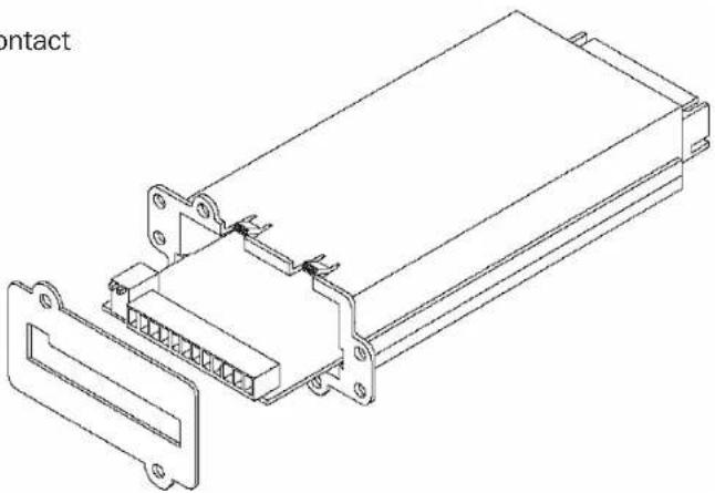
natural_image
Technical line drawing of an electronic component housing with mounting brackets and a separate panel (no text or symbols)2. Installation and Setup
2.1 System Requirements
The RELAYIOCARD supports all Tripp Lite SmartOnline™ UPS Systems and select SmartPro™ UPS Systems, including SMART1050SLT, SMART1500SLT, SMART2200RMXL2U, SMX1050SLT, SMX1500SLT, SMART3000SLT, SMART2200SLT, SM2200RMNAFTA, SMART2600RM2U, SMART3000RM2U, SMART1500CRMXL, SMART1500SLTXL, SMART750XLa, SMX3000XLRT2U and SMX2200XLRT2U. Supported systems must run a UPS protocol of 3008 or above.
To determine your UPS protocol:
- Open Tripp Lite PowerAlert software.
- Click on the "Misc" button on the main screen of the PowerAlert console.
- View the protocol variable.
2.2 Communications Setup
- Connect Tx to pin 2, Rx to pin 3 and GND-C to pin 5 of RS-232 DB9 port.
- In the Windows environment, launch the Hyper Terminal program, then open the specified COM port.
- Set the following properties – Baud rate: 2400, Data Bits: 8, Parity: None, Stop Bit: 1, Flow Control: None.
2. Installation and Setup (continued)
2.3 Configuration
- Press Enter to open the main menu of the RELAYIOCARD. Press 1 to configure the alarm event for R1\~R6.
![UPS Relay Card Firmware Version: Relay Card V1.4 [1].Customize Output Relay [2].Configure Input Signal [3] Customize Normal Open or Normal Close [0].Quit Please Enter Your Choice =>](/content/2026/05/1126707/images/6aeab0bbd0cfbfc47e6cb3f2a37b08d2b49747b57ffd315bdac8b11ab3943a9f.jpg)
- Note: Contacts R1\~R6 can be configured for different power events.
![+----+ | Customize Output Relay | +----+ Relay Selected Event [1].Relay1: Summary Alarm [2].Relay2: Power Fail [3].Relay3: Battery Low [4].Relay4: On Bypass [5].Relay5: Overload [6].Relay6: Over Temperature [0].Back To Previous Menu Please Enter Your Choice =>](/content/2026/05/1126707/images/2432a6aa916013c2b7a0d0e89c152e50f699b4c5e7b8aa96899f35cc2369b68d.jpg)
- Press 2 to configure the input signal.
In this menu, the input signal can be redefined as a shutdown UPS signal or battery test signal. The UPS shutdown delay time can be adjusted to a maximum of 9999 seconds.
![Configure Input Signal [1].Act as Shutdown or Test: Shutdown [2].Input Signal Confirm: 3 Seconds [3].Delay Before Shutdown: 30 Seconds [0].Back To Previous Menu Please Enter Your Choice =>](/content/2026/05/1126707/images/84b2e6a73f6e84c4f0c635a0ce4fbc89f67ef84dec69af11ec22198583271d4d.jpg)
- Press 3 to configure the normal open or normal close for each relay.
Once the configuration is complete, SW2 must be switched ON to apply the new settings. To automatically reset to default settings, switch SW2 to the OFF position.
![Customize Output Relay Relay Selected Event [1].Relay1: Normal Close [2].Relay2: Normal Open [3].Relay3: Normal Close [4].Relay4: Normal Open [5].Relay5: Normal Close [6].Relay6: Normal Open [0].Back To Previous Menu Please Enter Your Choice =>](/content/2026/05/1126707/images/eb350c71a4f27e1aa0a0ca3053abc6abd195b7385bb791d3629d3619aef03813.jpg)
- Press 0 to quit the configuration session. When the system prompts you to save your settings, press Y to save or N to ignore.
Application Example
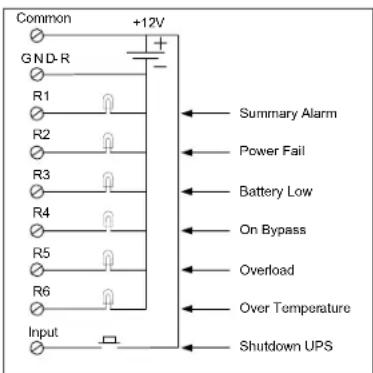
Using the default settings, set SW1 and SW2 to OFF. Apply 12V DC to Common contact and connect the lamps to R1\~R6 terminals. Install a push button from the Common contact to the input terminal. Press the button for at least 3 seconds to shut down the UPS remotely.
2. Installation and Setup (continued)
2.4 AS400 Configuration
- Press Enter to open the main menu of the RELAYIOCARD.
Press 1 to configure the alarm event for R1\~R6.
![UPS Relay Card Firmware Version: Relay Card V1.9 [1]. Customize Output Relay [2]. Configure Input Signal [3] Customize Normal Open or Normal Close [4] Reset to Default [0]. Quit Please Enter Your Choice =>](/content/2026/05/1126707/images/25c3adf1251dede0a83f9acd131deea6296e8d6896fcbb04366213fec77499b8.jpg)
- Select the On Bypass, Low Battery, On Standby and Power Fail for R1\~R4.
![Customize Output Relay Relay Selected Event [1]. Relay1: On Bypass [2]. Relay2: Low Battery [3]. Relay3: On Standby [4]. Relay4: Power Fail [5]. Relay5: Overload [6]. Relay6: UPS Disconnect [0]. Back To Previous Menu Please Enter Your Choice =>](/content/2026/05/1126707/images/1e49617fb1eafa33689518f6c5518a141bafba5d3c3233f9f1da4706080c1ec7.jpg)
- Press 0 to return to the main menu.
Then press 3 to configure the normally open or normally closed.
Select 3 to switch from Normal Open to Normal Closed for Relay 3 (On Standby Event).
![Customize Output Relay Relay Selected Event [1].Relay1: Normal Open [2].Relay2: Normal Open [3].Relay3: Normal Close [4].Relay4: Normal Open [5].Relay5: Normal Open [6].Relay6: Normal Open [0].Back To Previous Menu Please Enter Your Choice =>](/content/2026/05/1126707/images/a734e62786c3b8d36fc914a097f726092e42ec65a9d5bea68b8ce059ee89bf4e.jpg)
- Press 0 to return to the main menu.
Press 0 to quit the configuration.
When the "Save Before Exit?" prompt appears, select Y to save the configuration.
![UPS Relay Card Firmware Version: Relay Card V1.9 [1]. Customize Output Relay [2]. Configure Input Signal [3] Customize Normal Open or Normal Close [4] Reset to Default [0]. Quit Please Enter Your Choice => 0 Save Before Exit? [Y]es. [N]o : Y Data Saved.](/content/2026/05/1126707/images/081de52cf0611f80ba98e6dd0eee81d5ba21af239e2932256dbe42cec81be4f1.jpg)
-
Set the dip switch SW2 to the ON position for the RELAYIOCARD to begin using the custom settings for the AS400 connection.
-
Connect the RELAYIOCARD terminals to the AS400 DB9 connector as follows:
| Relay Card Pin | AS400 DB9 Pin | ||||
| Signal | Signal | Definition | |||
| GND-R | Ground for relay | 1 | |||
| Common | 12~24VDC | 2 | |||
| R1 | On Bypass | 3 | |||
| R2 | Low Battery | 4 | |||
| R3 | On Standby | 5 | Ground | ||
| R4 | Power Fail | 6 | On Bypass | Normal open | |
| R5 | Overload | 7 | Battery Low | Normal open | |
| R6 | Over Temperature | 8 | UPS On | Normal open | |
| Input | Remote Shutdown | 9 | Utility Line Fail | Normal open | |
3. Specifications
Technical Specifications
| Size 130 x 60 mm | |
| Weight 200g | |
| Operating Temperature 0 ~ 40°C | |
| Operating Humidity 10 ~ 80% | |
| Power Input 8~20V DC | |
| Power Consumption 1.2 Watts | |
Output Contact Rating
| Maximum | ||
| DC Voltage DC | Current | |
| Input 24V 1A | ||
Input Rating
| Maximum | ||
| DC Voltage DC | Current | |
| Input 24V 10mA | ||
Internal Circuit

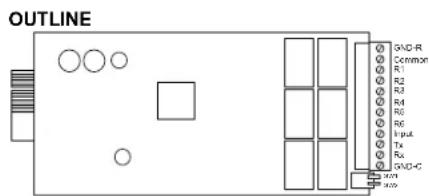
Outline
I/O Pinout
| GND-R: Ground for relays | ||
| Common: 12~24V DC | ||
| Default Alarm Event | ||
| R1 | Summary Alarm | |
| R2 | Power Fail | |
| R3 | Battery Low | |
| R4 | On Bypass | |
| R5 | Overload | |
| R6 | Over Temperature | |
| Input: Remote shutdown or battery test | ||
| Tx: Transmit to PC, connect to DB9-pin2 | ||
| Rx: Receive from PC, connect to DB9-pin3 | ||
| GND-C: Ground for configuration Tx and Rx pins | ||
| OFF (default) ON | ||
| SW1 | Normal open for default settings | Normal close for default settings |
| SW2 | Default settings | Customized settings |
4. Warranty & Warranty Registration
LIMITED WARRANTY
Seller warrants this product, if used in accordance with all applicable instructions, to be free from original defects in materials and workmanship for a period of 2 years (except internal UPS system batteries outside USA and Canada, 1 year) from the date of initial purchase. If the product should prove defective in material or workmanship within that period, Seller will repair or replace the product, in its sole discretion. Service under this Warranty can only be obtained by your delivering or shipping the product (with all shipping or delivery charges prepaid) to: Tripp Lite, 1111 W. 35th Street, Chicago, IL 60609, USA. Seller will pay return shipping charges. Call Tripp Lite Customer Service at (773) 869-1234 before sending any equipment back for repair.
THIS WARRANTY DOES NOT APPLY TO NORMAL WEAR OR TO DAMAGE RESULTING FROM ACCIDENT, MISUSE, ABUSE OR NEGLECT. SELLER MAKES NO EXPRESS WARRANTIES OTHER THAN THE WARRANTY EXPRESSLY SET FORTH HEREIN. EXCEPT TO THE EXTENT PROHIBITED BY APPLICABLE LAW, ALL IMPLIED WARRANTIES, INCLUDING ALL WARRANTIES OF MERCHANTABILITY OR FITNESS, ARE LIMITED IN DURATION TO THE WARRANTY PERIOD SET FORTH ABOVE; AND THIS WARRANTY EXPRESSLY EXCLUDES ALL INCIDENTAL AND CONSEQUENTIAL DAMAGES. (Some states do not allow limitations on how long an implied warranty lasts, and some states do not allow the exclusion or limitation of incidental or consequential damages, so the above limitations or exclusions may not apply to you. This Warranty gives you specific legal rights, and you may have other rights which vary from jurisdiction to jurisdiction.)
WARNING: The individual user should take care to determine prior to use whether this device is suitable, adequate or safe for the use intended. Since individual applications are subject to great variation, the manufacturer makes not representation or warranty as to the suitability or fitness of these devices for any specific application.
Not compatible with PoE (Power over Ethernet) applications.
WARRANTY REGISTRATION
Visit www.triplite.com/warranty today to register the warranty for your new Tripp Lite product. You'll be automatically entered into a drawing for a chance to win a FREE Tripp Lite product!*
* No purchase necessary. Void where prohibited. Some restrictions apply. See website for details.
Regulatory Compliance Identification Numbers
For the purpose of regulatory compliance certifications and identification, your Tripp Lite product has been assigned a unique series number. The series number can be found on the product nameplate label, along with all required approval markings and information. When requesting compliance information for this product, always refer to the series number. The series number should not be confused with the marking name or model number of the product.
Tripp Lite has a policy of continuous improvement. Product specifications are subject to change without notice.
201011142·932815-EN
| Relay Card Pin | AS400 DB9 Pin | ||||
| Signal | Signal | Definition | |||
| GND-R | Ground for relay | 1 | |||
| Common | 12~24VDC | 2 | |||
| R1 | On Bypass | 3 | |||
| R2 | Low Battery | 4 | |||
| R3 | On Standby | 5 | Ground | ||
| R4 | Power Fail | 6 | On Bypass | Normal open | |
| R5 | Overload | 7 | Battery Low | Normal open | |
| R6 | Over Temperature | 8 | UPS On | Normal open | |
| Input | Remote Shutdown | 9 | Utility Line Fail | Normal open | |
3. Especificaciones
2. Installation et configuration (suite)
2.4 Configuration des AS400
| Relay Card Pin | AS400 DB9 Pin | ||||
| Signal | Signal | Definition | |||
| GND-R | Ground for relay | 1 | |||
| Common | 12~24VDC | 2 | |||
| R1 | On Bypass | 3 | |||
| R2 | Low Battery | 4 | |||
| R3 | On Standby | 5 | Ground | ||
| R4 | Power Fail | 6 | On Bypass | Normal open | |
| R5 | Overload | 7 | Battery Low | Normal open | |
| R6 | Over Temperature | 8 | UPS On | Normal open | |
| Input | Remote Shutdown | 9 | Utility Line Fail | Normal open | |
3. Spécifications
1111 W. 35th Street, Chicago, IL 60609 USA +1.773.869.1234 • www.triplite.com
- Programmable Relay I/O Card Model: RELAYIOCARD
- Introduction 2
- Installation and Setup 2
- Specifications 5
- Warranty & Warranty Registration 5
- Introduction
- Product Features
- Package Contents
- This Package Contains:
- Installation and Setup
- System Requirements
- Communications Setup
- Installation and Setup (continued)
- Configuration
- Application Example
- AS400 Configuration
- Specifications
- Internal Circuit
- Warranty & Warranty Registration
- LIMITED WARRANTY
- WARRANTY REGISTRATION
- Regulatory Compliance Identification Numbers
- Especificaciones
- Installation et configuration (suite)
- Configuration des AS400
- Spécifications
Brand : Tripp Lite
Model : AS400CABLEKIT2
Category : Computer Cables