
ARMDUOSS - Flat screen mount StarTech.com - Free user manual and instructions
Find the device manual for free ARMDUOSS StarTech.com in PDF.


| Product Type | Dual Monitor Desk Mount |
| Brand | StarTech.com |
| Model | ARMDUOSS |
| VESA Compatibility | 75x75mm, 100x100mm |
| Weight Capacity per Screen | 8 kg (17.6 lbs) |
| Number of Screens Supported | 2 |
| Mounting Type | Desk clamp or grommet mount |
| Tilt Range | -5° to +15° |
| Swivel Range | ±90° per arm |
| Rotation | 360° |
| Arm Length | 500 mm (19.7 in) |
| Height Adjustment Range | 380 mm (15 in) |
| Cable Management | Integrated cable clips |
| Material | Steel, aluminum alloy, ABS plastic |
| Color | Matte black |
| Overall Dimensions (WxDxH) | 680 x 480 x 250 mm (26.8 x 18.9 x 9.8 in) |
| Net Weight | 5.2 kg (11.5 lbs) |
| Warranty | 3 years limited warranty |
| Included Items | Mount arms, clamp and grommet hardware, mounting screws, cable clips, user manual |
| Certifications | TUV, UL listed |
| Spare Parts Availability | Replacement arms, hardware, and gas springs available from StarTech.com |
Frequently Asked Questions - ARMDUOSS StarTech.com
User questions about ARMDUOSS StarTech.com
0 question about this device. Answer the ones you know or ask your own.
Ask a new question about this device
Download the instructions for your Flat screen mount in PDF format for free! Find your manual ARMDUOSS - StarTech.com and take your electronic device back in hand. On this page are published all the documents necessary for the use of your device. ARMDUOSS by StarTech.com.
USER MANUAL ARMDUOSS StarTech.com
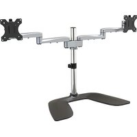
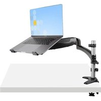
Articulating Dual-Monitor Stand - Aluminum

natural_image
Modern dual-axis airship mounted on a vertical pole with three propellers, no visible text or symbols*actual product may vary from photos
User Manual
SKU#: ARMDUALSS
Manual Revision: 04/29/2019
Compliance Statements
Use of Trademarks, Registered Trademarks, and other Protected Names and Symbols
This manual may make reference to trademarks, registered trademarks, and other protected names and/or symbols of third-party companies not related in any way to StarTech.com. Where they occur these references are for illustrative purposes only and do not represent an endorsement of a product or service by StarTech.com, or an endorsement of the product(s) to which this manual applies by the third-party company in question. Regardless of any direct acknowledgement elsewhere in the body of this document, StarTech.com hereby acknowledges that all trademarks, registered trademarks, service marks, and other protected names and/or symbols contained in this manual and related documents are the property of their respective holders.
PHILLIPS® is a registered trademark of Phillips Screw Company in the United States or other countries.
Safety Statements
- Product installation and/or mounting should be completed by a certified professional as per the local safety and building code guidelines.
- Cables (including power and charging cables) should be placed and routed to avoid creating electric, tripping or safety hazards.
Mesures de Sécurité
To view manuals, videos, drivers, downloads, technical drawings, and more visit www.startech.com/support
Warning Statements
• Make sure to assemble this product according to the instructions. Failure to do so might result in personal injury or property damage.
- Make sure that the weight of the monitors doesn't exceed the weight capacity of this product. If you exceed the weight capacity, you might experience personal injury or damage to the equipment. This product can support the following weight: 17.6 lb. (8 kg) per monitor mount.
- Never operate this product if parts are missing or damaged.
Varningsmeddelanden
To view manuals, videos, drivers, downloads, technical drawings, and more visit www.startech.com/support
To view manuals, videos, drivers, downloads, technical drawings, and more visit www.startech.com/support
注意
Safety Statements......ii
Warning Statements......iii
Product Information ....1
Package Contents .... 1
Product Diagram....2
Dimensions....2
Front View 3
Rear View....4
Side View 5
Technical Specifications....6
Requirements ....7
Assembly 8
Assemble the Base....8
Adjust the Collar 9
Attach the Shoulder 10
Attach the Swivel Arms....11
Attach the VESA Mounts to the Monitors....13
Attach the VESA Mounts to the Swivel Arms 15
Adjusting the Monitors 16
Tilt Adjustment 16
Swivel Adjustment....17
Micro Height Adjustment....17
Cable Management....18
Product Information
Package Contents
 |  |  |  |
| Swivel ArmsQty: Two | PoleQty: One | BaseQty: One | ShoulderQty: One |
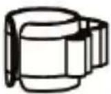 |  | 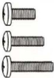 |  |
| Cable-Management ClipsQty: One | VESA MountsQty: Two | Screws:M4x12 mmM4x16 mmM4x20 mmQty: Eight of each | Screws:M5x12 mmM5x16 mmM5x20 mmQty: Eight of each |
 |  | 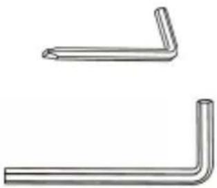 |  |
| WashersQty: Eight | SpacersQty: Sixteen | 3 mm Hex Key6 mm Hex KeyQty: One of each | User ManualQty: One |
Product Diagram
Dimensions

To view manuals, videos, drivers, downloads, technical drawings, and more visit www.startech.com/support
Front View

| 1 | VESA Mounts |
| 2 | Swivel Arms |
| 3 | Pole |
| 4 | Base |
To view manuals, videos, drivers, downloads, technical drawings, and more visit www.startech.com/support
Rear View
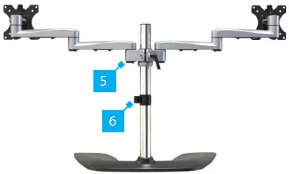
| 5 | Shoulder |
| 6 | Cable-Management Clip |
To view manuals, videos, drivers, downloads, technical drawings, and more visit www.startech.com/support
Side View

natural_image
Mechanical device with articulated arms and a curved base, labeled with number 7 (no text or symbols on the device itself)7
Height-Adjustment Lever
To view manuals, videos, drivers, downloads, technical drawings, and more visit www.startech.com/support
Technical Specifications
Type of Measurement Measurement
| VESA Mounting Hole Pattern | |
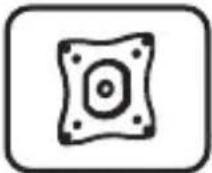 | 75x75100x100 |
| Weight Capacity | |
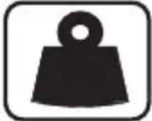 | Up to 17.6 lb. (8 kg)Per Monitor |
| Tilt | |
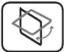 | +90° to -40° |
| Maximum Screen Size | |
 | 32" (813 mm) |
| Rotate | |
 | +180° to -180° |
| Swivel | |
 | +90° to -90° |
To view manuals, videos, drivers, downloads, technical drawings, and more visit www.startech.com/support
Requirements
For the latest requirements, please visit www.StarTech.com/ARMDUALSS.
- Two Monitors
Note: Both Monitors must conform to the size, weight, and VESA pattern requirements (see Technical Specifications).
• Phillips Head Screwdriver
• (Optional) Two People for Installation
Assembly
Warning! Make sure that all of the hardware is assembled securely and checked for stability before you load the Monitors.
Warning! Make sure that the weight of the Monitors does not exceed the weight capacity of this product. If you exceed the weight capacity, you might experience personal injury or damage to the product.
Assemble the Base
- Loosen the Hex Screws that are located on the Base using the 3 mm Hex Key.
- Slide the Cable-Management Clip onto the Pole.
- Screw the Pole into the Base.
- Tighten the Hex Screws that are located on the Base using the 3 mm Hex Key. (Figure 1)

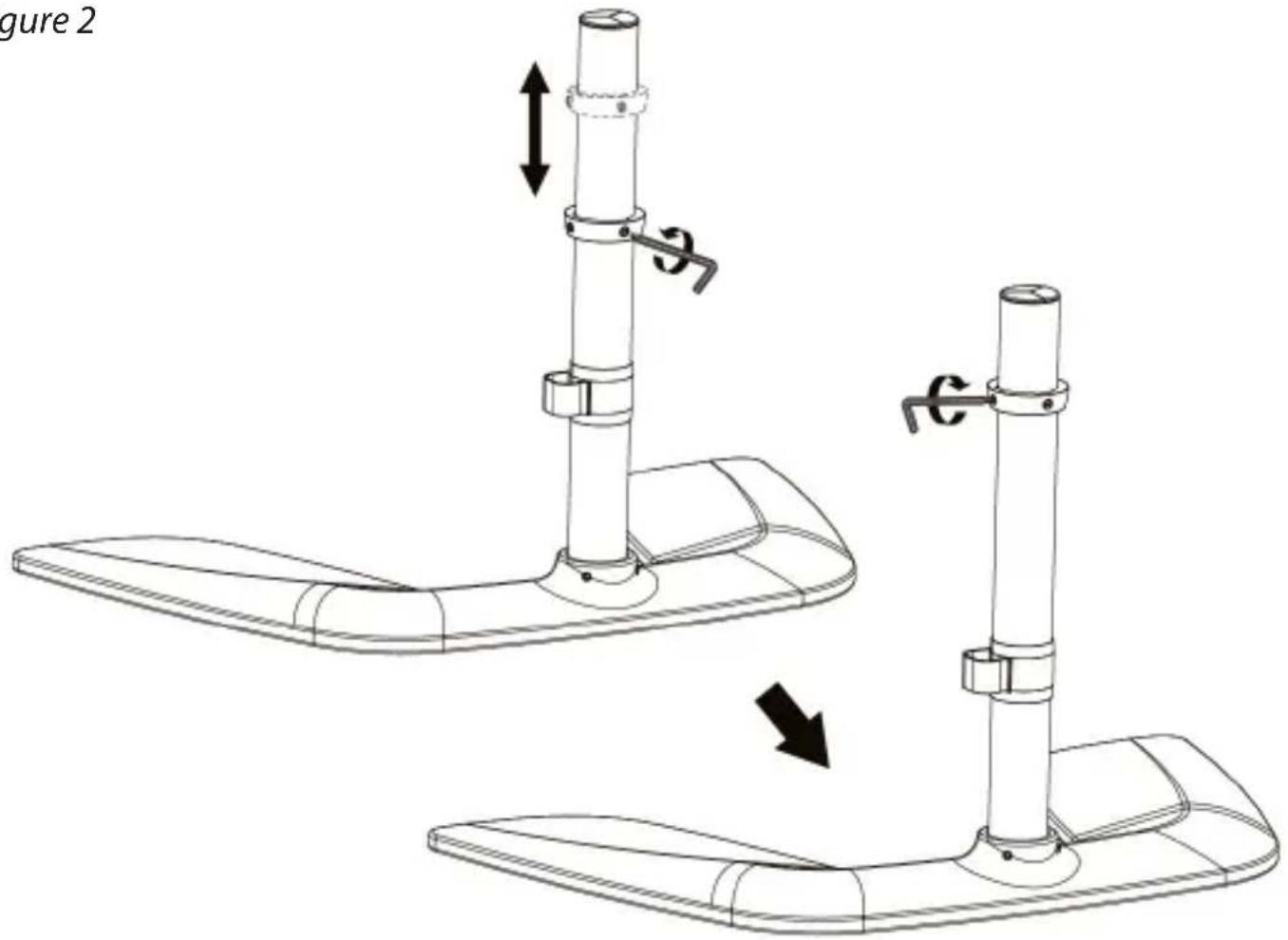
Adjust the Collar
-
Loosen the Flat-Head Screws on the Collar, using the 3 mm Hex Key with Screwdriver Tip.
-
Slide the Collar up or down the Pole so that it sits at the desired height for your Monitors.
-
Tighten the two Flat-Head Screws that are located on the Collar, using the 3 mm Hex Key with Screwdriver Tip. (Figure 2)
To view manuals, videos, drivers, downloads, technical drawings, and more visit www.startech.com/support
Figure 2
Attach the Shoulder
- Rotate the Lever on the Shoulder counterclockwise to loosen the Shoulder.
Note: The Lever has a ratchet feature. Freely rotate the Lever by pulling it away from the Shoulder and rotating it to the desired position.
-
Slide the Shoulder over and down the Pole, until it makes contact with the Collar.
-
Rotate the Lever on the Shoulder clockwise to tighten the Shoulder. (Figure 3)
To view manuals, videos, drivers, downloads, technical drawings, and more visit www.startech.com/support
Figure 3

Attach the Swivel Arms
- Insert the Swivel Arms into the Sockets of the Shoulder until each Swivel Arm clicks into place. (Figure 4)
To remove the Swivel Arms: Release the Clip that is located on the bottom of the Swivel Arms, where the Swivel Arms connect to the Shoulder, and pull upwards.
To view manuals, videos, drivers, downloads, technical drawings, and more visit www.startech.com/support
Figure 4

To view manuals, videos, drivers, downloads, technical drawings, and more visit www.startech.com/support
Attach the VESA Mounts to the Monitors
ARMDUALSS is designed to be used with Monitors that are the same size and weight. If you attach Monitors that are different sizes and weights to ARMDUALSS, you do so at your own risk.
To accommodate different Monitor designs, ARMDUALSS comes with six sets of Screws that are different lengths and diameters.
To select the appropriate Screws for the type of Monitors that you are using, complete the following:
- Determine whether the Monitor's VESA Mounting Hole Patterns are flush or inset. Inset mounts may require the use of the Spacers.
- Determine the depth of the Mounting Holes on the Monitors.
-
Determine the diameter of the Mounting Holes on the Monitors.
-
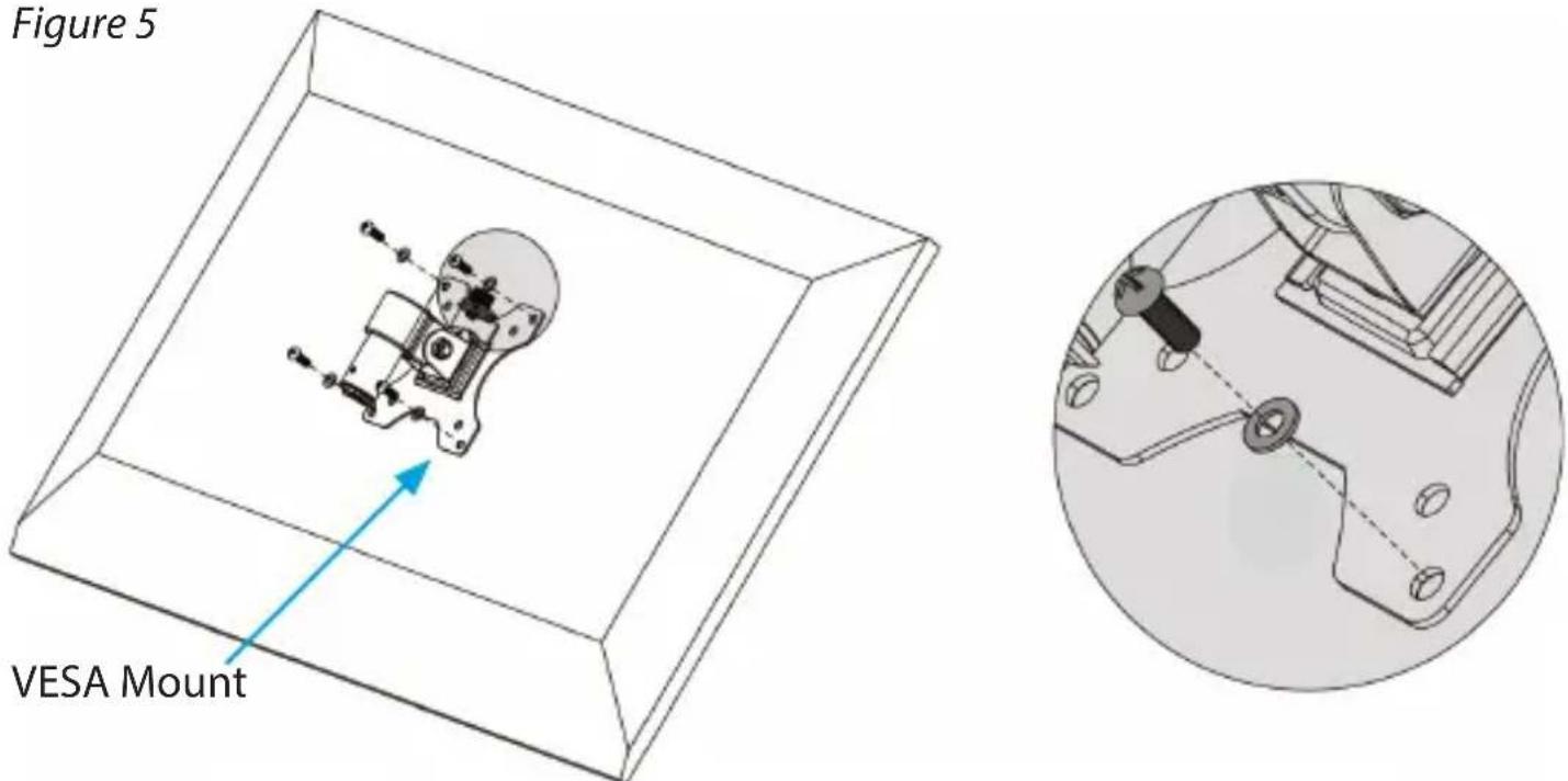
Position one of the VESA Mounts over the Mounting Holes on the back of one of the Monitors.
Note: Make sure that you position the VESA Adapter so that the Height-Adjustment Lever on the VESA Mount is facing towards the top of the Monitor.
-
Position four of the Washers over the holes on the VESA Mount.
-
Insert four of the appropriately sized Screws through the Washers, the VESA Mount, and into the Monitor. (Figure 5)
To view manuals, videos, drivers, downloads, technical drawings, and more visit www.startech.com/support
- (Optional) Place one or more Spacers between the Holes in the Monitor and the VESA Mount, to ensure it is flat against the Monitor. (Figure 6)

- Use a Phillips Head Screwdriver to tighten the Screws.
To view manuals, videos, drivers, downloads, technical drawings, and more visit www.startech.com/support
Warning! Do not over-tighten the Screws. If you encounter resistance while you're tightening the Screws, stop tightening. Failure to do so could result in damage to the Monitor.
- Complete steps 1 to 4 to add a VESA Mount to a second Monitor.
Attach the VESA Mounts to the Swivel Arms
Note: A second person may be required to complete the following steps.
- Lift the Monitor that will be positioned on the left-hand side and position it over the Swivel Arm Receptacle.
- Insert the cylindrical portion of the VESA Mount into the Swivel Arm Receptacle on the left-hand side until you hear the VESA Mount click into place. (Figure 7)
- Repeat steps 1-2 for the Monitor on the right-hand side.
Figure 7

natural_image
Technical line drawing of a mechanical assembly with two views and a magnified inset showing internal components (no text or symbols)Adjusting the Monitors
Warning! The most stable configuration of ARMDUALSS is the "flat" position, with both of the Swivel Arms positioned in a straight line. ARMDUALSS can become unstable depending on how you position the Monitors. If you adjust the position of the Monitors, you should exercise caution and test the stability of ARMDUALSS before you use it in the adjusted configuration.
Tilt Adjustment
The Monitors can be tilted to accommodate different viewing angles (40 degrees downward or 90 degrees upward).
- Loosen the Hex Screw on the side of each VESA Mount by inserting the 6 mm Hex Key and turning it counterclockwise until the Monitor can easily be reoriented.
Note: It is not necessary to fully loosen the Hex Screws to adjust the tilt of the Monitors.
- Place both of your hands on either side of the Monitor and apply light pressure either forwards or backwards.
- When the Monitor is in the desired position, tighten the Hex Screw on each VESA Mount by inserting the 6 mm Hex Key and turning it clockwise until the Hex Screw is hand tight. (Figure 8)
Note: A second person may be required to hold the Monitors as you tighten the Hex Screws.
To view manuals, videos, drivers, downloads, technical drawings, and more visit www.startech.com/support
Figure 8

Swivel Adjustment
The Monitors can be adjusted on a 90-degree swivel.
- Place both of your hands on either side of the Monitor and apply light pressure either left or right.
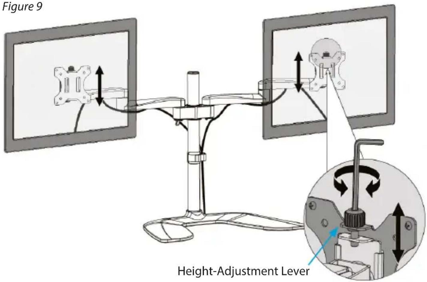
Micro Height Adjustment
- Insert the 6 mm Hex Key into the Height-Adjustment Lever that is located on the top of the VESA Mounts.
- Turn the 6 mm Hex Key, or the Height-Adjustment Lever, clockwise to raise the Monitors or counterclockwise to lower the Monitors. (Figure 9)
To view manuals, videos, drivers, downloads, technical drawings, and more visit www.startech.com/support
Cable Management
The Power and Video Cables from your Monitors can be organized and contained within the Swivel Arms and alongside the Pole. To manage the Cables running to your Monitors, complete the following steps:
-
Connect the Power and Video Cables to each Monitor.
-
Route the Cables for the Monitor along the bottom of the Swivel Arm on the left-hand side.
-
Locate the integrated Cable-Management Channels within the Swivel Arm and gently press the Cables into the Channels.
To view manuals, videos, drivers, downloads, technical drawings, and more visit www.startech.com/support
Note: If the Cables do not readily snap into the Cable- Management Channels, gently pull back one side of the Cable-Management Channel and feed the Cables into the Channel.
Figure 10

- Route the Cables along the Pole, through the Cable-Management Clip, and towards the Video Source and Power Source.
To view manuals, videos, drivers, downloads, technical drawings, and more visit www.startech.com/support
Warranty Information
This product is backed by a five-year warranty.
For further information on product warranty terms and conditions, please refer to www.startech.com/warranty.
Limitation of Liability
In no event shall the liability of StarTech.com Ltd. and StarTech.com USA LLP (or their officers, directors, employees or agents) for any damages (whether direct or indirect, special, punitive, incidental, consequential, or otherwise), loss of profits, loss of business, or any pecuniary loss, arising out of or related to the use of the product exceed the actual price paid for the product.
Some states do not allow the exclusion or limitation of incidental or consequential damages. If such laws apply, the limitations or exclusions contained in this statement may not apply to you.
Hard-to-find made easy. At StarTech.com, that isn't a slogan. It's a promise.
StarTech.com is your one-stop source for every connectivity part you need. From the latest technology to legacy products — and all the parts that bridge the old and new — we can help you find the parts that connect your solutions.
We make it easy to locate the parts, and we quickly deliver them wherever they need to go. Just talk to one of our tech advisors or visit our website. You'll be connected to the products you need in no time.
Visit www.startech.com for complete information on all StarTech.com products and to access exclusive resources and time-saving tools.
StarTech.com is an ISO 9001 Registered manufacturer of connectivity and technology parts. StarTech.com was founded in 1985 and has operations in the United States, Canada, the United Kingdom and Taiwan servicing a worldwide market.
Reviews
Share your experiences using StarTech.com products, including product applications and setup, what you love about the products, and areas for improvement.
StarTech.com Ltd.
45 Artisans Cres.
London, Ontario
N5V 5E9
Canada
StarTech.com LLP
2500 Creekside Pkwy.
Lockbourne, Ohio
43137
U.S.A.
StarTech.com Ltd.
Unit B, Pinnacle
15 Gowerton Rd., Brackmills
Northampton
NN4 7BW
United Kingdom
FR: fr.startech.com
DE: de.startech.com
ES: es.startech.com
NL: nl.startech.com
IT: it.startech.com
JP: jp.startech.com
- Articulating Dual-Monitor Stand - Aluminum
- User Manual
- Compliance Statements
- Use of Trademarks, Registered Trademarks, and other Protected Names and Symbols
- Safety Statements
- Mesures de Sécurité
- Warning Statements
- Varningsmeddelanden
- 注意
- Product Information
- Package Contents
- Product Diagram
- Dimensions
- Front View
- Rear View
- Side View
- Technical Specifications
- Requirements
- Assembly
- Assemble the Base
- Adjust the Collar
- Attach the Shoulder
- Attach the Swivel Arms
- Attach the VESA Mounts to the Monitors
- Attach the VESA Mounts to the Swivel Arms
- Adjusting the Monitors
- Tilt Adjustment
- Swivel Adjustment
- Micro Height Adjustment
- Cable Management
- Warranty Information
- Limitation of Liability
- Hard-to-find made easy. At StarTech.com, that isn't a slogan. It's a promise.
- Reviews
Brand : StarTech.com
Model : ARMDUOSS
Category : Flat screen mount