
DVI-PROWALL-12X - Uncategorized Avenview - Free user manual and instructions
Find the device manual for free DVI-PROWALL-12X Avenview in PDF.


| Product Type | 12-Display Videowall Processor |
| Model | DVI-PROWALL-12X |
| Input Ports | 2x DVI/HDMI, 1x VGA, 1x Component |
| Output Ports | 12x DVI-D/HDMI |
| Control Interface | RS-232, Ethernet (RJ-45) |
| Supported Input Resolutions | Up to 1080p (HDMI), WUXGA 1920x1200 (VGA/Component) |
| Supported Output Resolutions | 800x600 to 1920x1200 @60Hz |
| Video Bandwidth | DVI: 4.95Gbps, HDMI: 2.25-6.75Gbps, Component: 30MHz |
| Video Wall Modes | PIP, PAP, Full Screen, Custom layout with adjustable size and position |
| Rotation | Input rotation supported (full screen mode only) |
| HDCP Compliance | Yes |
| Power Supply | AC 100-240V, 60W max |
| Dimensions (L x W x H) | 438mm x 438mm x 89mm (17.25" x 17.25" x 3.5") |
| Weight (unit) | 13.6 kg (30 lbs) |
| Enclosure | Metal, 2.5 RU, rack-mountable with ears, wall-mountable |
| Operating Temperature | 0°C to 40°C (32°F to 104°F) |
| Storage Temperature | -20°C to 60°C (-4°F to 140°F) |
| Safety Precautions | Do not dismantle; keep away from liquids; use only provided power cord; refer servicing to qualified personnel |
| Cleaning | Unplug before cleaning; use a dry cloth; do not use liquid or aerosol cleaners |
| Package Contents | Main unit, installation software CD, 2x DVI-to-HDMI adapters, 1x VGA-to-Component breakout cable, AC power cord, rack ear set, user manual |
| Warranty | 3 years parts and labor (with registration) |
| Firmware Update | Via USB and software (input and output cards separate) |
| EDID Learning | Supported via software; default EDIDs available |
Frequently Asked Questions - DVI-PROWALL-12X Avenview
User questions about DVI-PROWALL-12X Avenview
0 question about this device. Answer the ones you know or ask your own.
Ask a new question about this device
Download the instructions for your Uncategorized in PDF format for free! Find your manual DVI-PROWALL-12X - Avenview and take your electronic device back in hand. On this page are published all the documents necessary for the use of your device. DVI-PROWALL-12X by Avenview.
USER MANUAL DVI-PROWALL-12X Avenview
12 Display Videowall Processor with Rotation





Model #: DVI-PROWALL-12X
Product Application & Market Sectors

Corporate

House Of Worship

Military Resident


Education Indust


Medical Aviation

TABLE OF CONTENTS
I.1 IMPORTANT SAFEGUARDS....3
1.2 SAFETY INSTRUCTIONS....3
1.3 REGULATORY NOTICES FEDERAL COMMUNICATIONS COMMISSION (FCC)......4
- INTRODUCTION AND FEATURES....5
2.1 PACKAGE CONTENTS....6
2.2 BEFORE INSTALLATION....7
2.2.1 CABLE SPECIFICATIONS....7
- INSTALLATION (DVI-PROWALL-I2X)
3.1 APPLICATION DIAGRAM....9
3.2. PANEL DESCRIPTION....10
3.2.1 FRONT PANEL (DVI-PROWALL-12X) 10
3.2.2 REAR PANEL (DVI-PROWALL-12X) 10
-
SUPPORTED RESOLUTION......11
-
SOFTWARE OPERATION (DVI-PROWALL-12X)....12
-
EDID LEARNING......22
SECTION 7: SPECIFICATIONS....23
I.1 IMPORTANT SAFEGUARDS
Please read all instructions carefully before you use the device. Save this manual for future reference.
What the warranty does not cover
• Any product, on which the serial number has been defaced, modified or removed.
• Damage, deterioration or malfunction resulting from:
- Accident, misuse, neglect, fire, water, lightning, or other acts of nature, unauthorized product modification, or failure to follow instructions supplied with the product.
• Repair or attempted repair by anyone not authorized by us.
• Any damage of the product due to shipment.
• Removal or installation of the product.
• Causes external to the product, such as electric power fluctuation or failure.
• Use of supplies or parts not meeting our specifications.
• Normal wear and tear.
• Any other causes which does not relate to a product defect.
• Removal, installation, and set-up service charges.
1.2 SAFETY INSTRUCTIONS
The DVI-PROWALL-12X Display Videowall Processor has been tested for conformance to safety regulations and requirements, and has been certified for international use. However; like all electronic equipments, the DVI-PROWALL-12X should be used with care and precaution. Read the following safety instructions to protect yourself from possible injury and to minimize the risk of damage to the unit.
Do not dismantle the housing or modify the module.
Dismantling the housing or modifying the module may result in electrical shock or burn.
⚠️ Refer all servicing to qualified service personnel.
Do not attempt to service this product yourself as opening or removing housing may expose you to dangerous voltage or other hazards.
Keep the module away from liquids.
Spillage into the housing may result in fire, electrical shock, or equipment damage. Should an object or liquid falls or spills on to the housing, unplug the module immediately.
Have the module checked by a qualified service engineer before using it again.
Do not use liquid or aerosol cleaners to clean this unit. Always unplug the power to the device before cleaning.
1.3 REGULATORY NOTICES FEDERAL COMMUNICATIONS COMMISSION (FCC)
This equipment has been tested and found to comply with Part 15 of the FCC rules. These limits are designed to provide reasonable protection against harmful interference in a residential installation. Any changes or modifications made to this equipment may void the users authority to operate this equipment.
Warning Symbols

Description
ONLY USE THE PROVIDED POWER CABLE OR POWER ADAPTER SUPPLIED. DO NOT TAMPER WITH THE ELECTRICAL PARTS. THIS MAY RESULT IN ELECTRICAL SHOCK OR BURN.

DO NOT TAMPER WITH THE UNIT. DOING SO WILL VOID THE WARRANTY AND CONTINUED USE OF THE PRODUCT.


BEWARE this unit contains static sensitive devices
THE VIDEO BOARDS ARE VERY SENSITIVE TO STATIC. PLEASE ENSURE IF RACK MOUNTED OR INSTALLED ON A SURFACE, IT SHOULD BE IN A GROUNDED ENVIRONMENT.

natural_image
Blue circular icon with a white human figure holding an open book (no text or symbols)WARNING
Read & understand user guide before using this device.
Failure to follow the proper installation instructions could result in damage to the product and preventing expected results.
2. INTRODUCTION
The DVI-PROWALL-12x 12-Displays Video Wall Processor was developed to meet and accommodate the video resolution of up to 1080p.
This unit can support up to 12 DVI/HDMI outputs to expand the spectrum of video wall applications, because of its modular add-on card design concept, users can therefore modify the number of output ports based on different scenarios. The bandwidth of the video can be controlled by any PC/laptop either via Ethernet or RS232 control.
These control modules and control software has been revised for quick and easy setup within any environment. The DVI-PROWALL-12X allows you to input 2 DVI/HDMI – supporting up to 1080p and the VGA/Component port supports up to WUXGA (1920x1200).
FEATURES
- Up to 12 DVI outputs from 640x480 to 1920x1080, 1920x1200;
- Supports HDMI input resolution up to 1080p/WUXGA;
- Supports VGA and Component input format from 640x480 to 1920x1200, interfaced or progressive;
- PIP, side-by-side (PAP), full screen modes and adjustable size and position through software;
- Resize, position, flip, zoom output video;
- Each DVI output has and independent controllable display area;
- User-selectable output settings, up to Full HD 1080p, 1920x1200;
- Software control through RS-232 and Ethernet;
- PCIE-interface add-on card design;
- Perfectly as a video screen splitter, a video converter and a video switcher;
- HDCP compliant;
- Supports input rotation;
- 2.5 RU size.
2.1 PACKAGE CONTENTS
Before you start the installation of the converter, please check the package contents.
| 1 | I x DVI-PROWALL-I2X |  |
| 2 | Installation Software |  |
| 3 | 2 x DVI to HDMI AdapterI x VGA to Component Breakout Cable | 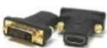  |
| 4 | AV Power Cord |  |
| 5 | I x Right and Left Ear Rack Sets |  |
| 6 | User's Manual |  |
2.2 BEFORE INSTALLATION
- Put the product in an even and stable location. If the product falls down or drops, it may cause an injury or malfunction.
- Do not place the product in high temperature (over 50°C), low temperature (under 0°C) or high humidity.
- Use the DC power adapter with correct specifications supplied with the unit. If improper power supply is used the unit may malfunction and cause a fire.
- Do not twist or pull by force ends of the video cable. It can cause malfunction.
2.2.1 CABLE SPECIFICATIONS

natural_image
Close-up of two black HDMI cables with gold connectors, no visible text or symbols on the cables themselves.
HIGH DEFINITION MULTIMEDIA INTERFACE
To achieve best results with our DVI-PROWALL-12X we highly recommend a premium quality 26 or 24 AWG HDMI cable with the below specifications to maintain signal integrity and distances.
FEATURES:
• Length: 5m (16ft) to 15m (50ft)
• Bandwidth: 10.2 Gbps data transfer rate
• Conductor gauge: 26 / 24 AWG
- Deep Color
• 3D Capable
• CEC
- Ethernet Channel
• Audio Return Channel
• Connector I: HDMI (Type A) Male
• Connector 2: HDMI (Type A) Male
• Supports Resolution: Up to 3840x2160 @ 24Hz and 4096x2160 @ 24Hz, 1080p @ 24Hz / 50/60Hz/3D
3.
INSTALLATION (DVI-PROWALL-12X)
I. Connect your source device such as digital signage player to DVI/HDMI Inputs on the DVI-PROWALL-12X.
2. Connect all displays/screens to DVI/HDMI Outputs on the DVI-PROWALL-12X.
3. Power up the DVI-PROWALL-12X.
4. Switch on all devices connected and then control the display output through RS-232, Ethernet and software.
GENERAL INSTRUCTIONS
- Before you begin the software installation from the CD provided or latest CS from the website, please ensure the DVI-PROWALL-12X is connected to AC power and your PC via USB or connected to the same network as the DVI-PROWALL-12X
- PC Requirements-Windows® XP/Windows Vista®/Windows® 7
- Ensure your laptop or desktop is plugged into AC power during the update process. It is not recommended to use only battery power during the installation. Do not remove power at any time during the process as this could lead to incomplete results. See Section 5 Operation Method B Software Control for more information.

flowchart
graph TD
    A["HDMI SOURCE 1 1080p@60"] --> B["AVENVIEW"]
    C["HDMI SOURCE 2 3840 x 2160"] --> B
    D["VGA /COMPONENT SOURCE 1 1920X1200"] --> B
    E["PC Control Software USB to RS-232"] --> F["DVI-PROWALL-12X"]
    B --> G["RS-232"]
    B --> H["ID"]
    B --> I["RS-485"]
    B --> J["ON/OFF"]
    B --> K["DVI OUTPUT 1"]
    B --> L["DVI OUTPUT 4"]
    B --> M["DVI OUTPUT 7"]
    B --> N["DVI OUTPUT 10"]
    B --> O["DVI OUTPUT 2"]
    B --> P["DVI OUTPUT 5"]
    B --> Q["DVI OUTPUT 8"]
    B --> R["DVI OUTPUT 11"]
    B --> S["DVI OUTPUT 3"]
    B --> T["DVI OUTPUT 6"]
    B --> U["DVI OUTPUT 9"]
    B --> V["DVI OUTPUT 12"]
    style A fill:#f9f,stroke:#333
    style C fill:#f9f,stroke:#333
    style D fill:#f9f,stroke:#333
    style E fill:#ccf,stroke:#333
    style F fill:#ccf,stroke:#333
    style G fill:#dfd,stroke:#333
    style H fill:#dfd,stroke:#333
    style I fill:#dfd,stroke:#333
    style J fill:#dfd,stroke:#333
    style K fill:#dfd,stroke:#333
    style L fill:#dfd,stroke:#333
    style M fill:#dfd,stroke:#333
    style N fill:#dfd,stroke:#333
    style O fill:#dfd,stroke:#333
    style P fill:#dfd,stroke:#333
    style Q fill:#dfd,stroke:#333
    style R fill:#dfd,stroke:#333
    style S fill:#dfd,stroke:#333
    style T fill:#dfd,stroke:#333
DVI-PROWALL-12X
LAYOUT 1- DUAL INPUT VIDEOWALL PICTURE IN PICTURE
CABLE INDEX
Output
Input / Source
RS-232
CAT-5 / CAT-6
4X3 VIDEOWALL

natural_image
Scenic waterfall surrounded by lush green forest, with a Windows Live desktop window displaying 'Windows Live' and app icons (no text on the waterfall itself)
flowchart
graph TD
    A["HDMI SOURCE 1 1080p@60"] --> B["AVerview"]
    C["HDMI SOURCE 2 3840 x 2160"] --> B
    D["VGA / COMPONENT SOURCE 1 1920X 1200"] --> B
    E["PC Control Software USB to RS-232"] --> F["DVI-PROWALL-12X"]
    B --> G["RS-232"]
    B --> H["ID"]
    B --> I["RS-485"]
    B --> J["ON/OFF"]
    B --> K["DV OUTPUT 1"]
    B --> L["DV OUTPUT 4"]
    B --> M["DV OUTPUT 7"]
    B --> N["DV OUTPUT 10"]
    B --> O["DV OUTPUT 2"]
    B --> P["DV OUTPUT 5"]
    B --> Q["DV OUTPUT 8"]
    B --> R["DV OUTPUT 11"]
    B --> S["DV OUTPUT 3"]
    B --> T["DV OUTPUT 6"]
    B --> U["DV OUTPUT 9"]
    B --> V["DV OUTPUT 12"]
3.2. PANEL DESCRIPTION
3.2.1 FRONT PANEL (DVI-PROWALL-I2X)

3.2.2 REAR PANEL (DVI-PROWALL-12X)

| 1. POWER SUPPLY: Power Cord supplied with unit | 2. INPUT PORT: DVI/HDMI Input |
| 3. INPUT PORT: DVI/HDMI input, supports input resolution up to 1080p | 4. INPUT PORT: VGA/Component input |
| 5. RS232 CONTROL: RS232 control port | 6. POWER SWITCH: Power ON/OFF switch |
| 7. ETHERNET CONTROL: Ethernet control port | 8. OUTPUT PORT I-9: DVI/HDMI outputs |
4. SUPPORTED RESOLUTION
| Input Resolution Supported | ||
| HDMI | VGA | Component (YPbPr) |
| 640x480 | 800x600 @60Hz | EIA 720x480p @59.95(60)Hz |
| 720x480 | 1024x768 @60Hz | EIA 720x576p @50Hz |
| 720x576 | 1280x720 @60Hz | EIA 1280x720p @59.94 (60)Hz |
| 800x600 | 1280x768 @60Hz | EIA 1920x1080i @59.94(60)Hz |
| 1024x768 | 1280x960 @60Hz | EIA 1920x1080p @59.94(60)Hz |
| 1152x864 | 1280x1024 @60Hz | |
| 1280x720 | 1360x768 @60Hz | |
| 1280x768 | 1400x1080 @60Hz | |
| 1280x800 | 1600x1200 @60Hz | |
| 1280x960 | 1920x1080 @60Hz | |
| 1280x1024 | ||
| 1360x768 | ||
| 1366x768 | ||
| 1400x1050 | ||
| 1440x240 | ||
| 1440x288(576i) | ||
| 1440x900 | ||
| 1600x900 | ||
| 1600x1200 | ||
| 1680x1050 | ||
| 1920x540(1080i) | ||
| 1920x1080 | ||
| 1920x1200 | ||
| Output Resolution Supported |
| 800x600@60 |
| 1024x768@60 |
| 1280x720@60 |
| 1280x1024@60 |
| 1366x768@60 |
| 1440x900@60 |
| 1440x1050@60 |
| 1600x1200@60 |
| 1920x1080@60 |
| 1920x1200@60 |
5. SOFTWARE OPERATION
System Requirement and Precautions
- Whenever powering off the DVI-PROWALL-12X, please stay unpowered for at least 5 to 10 seconds to allow power capacitors to discharge.
- The DVI-PROWALL-12X provides software control program which runs under Microsoft Windows 98, 2000, XP, 7 through the interface of RS-232 serial control.
- Before you click on the icon of the software, make sure you have secured the connection between your computer COM port and the DVI-PROWALL-I2X.
Start the software control program
When clicking on the executable file, the following dialog will pop-up. It has two ways to control the DVI-PROWALL-12X device (under Microsoft Windows 7, please run as administrator). RS-232 serial Mode: Use RS-232 to connect the port on device and computer. Select correct COM port
and click the √ button.
Ethernet Mode: Enter the device IP address and click the button.

After the software control setting is accomplished, it will enter directly to control interface.
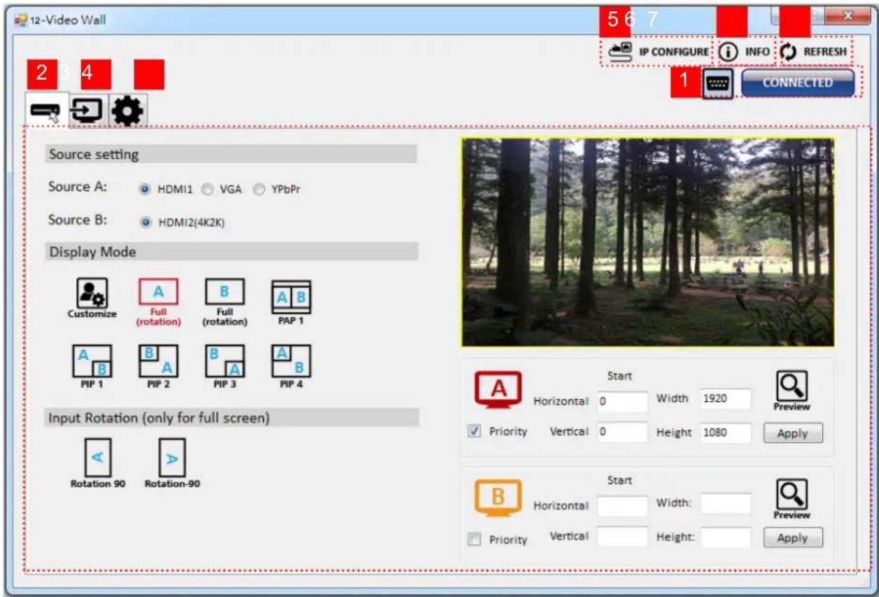
Control Interface
- Connection Status:
Show the connect information and status. If you use RS-232 serial control Mode to connect device the graph is 📄. In contrast, the graph of Ethernet is 📄.
- Input Control:
In this part, you can set up the input source, source display mode and screen rotation.
(I) Source setting
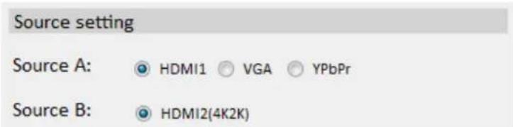
Set the Input source. You can select at most two input source.
(2) Display mode
Display Mode




In here, we provide 7 default mode and one customize mode for you to select.
natural_image
Forest scene with tall trees and a person walking, enclosed in a red bounding box (no visible text or symbols)
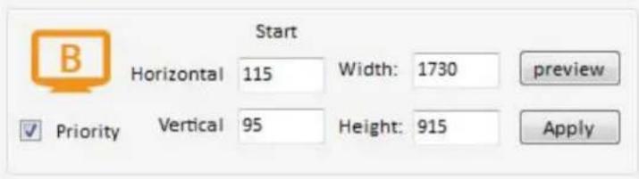
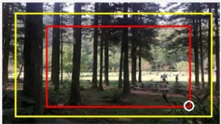
In the right part of control interface, it supply user to customize the display mode.
The different color of frame represents the different input source. The information of coordinate shows the position of input source screen. In a different color frame, it will show a white circle in the right corner. User can slide the white circle to resize the input source screen or adjust the position by setting coordinates, use can also can click the ☑ Priority button to make the window precedence.
(3) Input Rotation
Please take a closer look at this function. This function for full screen mode use only.
When full screen mode is selected, the following window will pop-up. Two directions to rotate the input screen is available.

3. Output Control
In this part, user can set up the output resolution, display setting and the output's brightness and contrast.
(I) Output Resolution
Set the output resolution. User can choose the desired display icon to select the output port and setup resolution. When setting the different resolution, the coordinate of output will also be changed.

(2) Display setting
It has two modes can set up the display.
Customize
In Custom define mode, user can slide the white circle to adjust the size of the output screen or input the number to adjust the coordinate. In addition, if user want to understand or estimate which part you may select, it also can select the button to show grid on the graph. After the setting, please click Grid

natural_image
Forest scene with tall trees and a person walking, no visible text or symbolsSelected Output: Output 1

Grid

None
Coordination in input
Horizontal start: 0
Width: 1530
Apply
Vertical start: 0
Height: 900
Quick Select
Display Setting

Customize

Quick Select
Horizontal cut: 1
Vertical cut: 1
Number: 1

In Quick Select mode, user can define how to cut in both directions and the image you want to display.
TV. (3) Contrast/Brightness
In here, user can adjust the brightness and contrast of output.
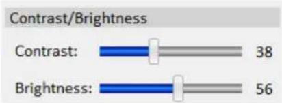
bar
Contrast/Brightness | Category | Value | |---|---| | Contrast: | 38 | | Brightness: | 56 |4. Advancing setting

(I) File Options

User can click the button to save all configuration for future use.
The button is for loading and to read configuration settings from existing files.
(2) Learn EDID
Select Default EDID (1-4 default EDID).

(The default EDID of 4K2K only suit for HDMI 2)
Select Input.
Click the Learn button to learn default EDID.
(3) View EDID content
Select the EDID input source (HDMI 1, HDMI 2).
Click View button to read the EDID description and analysis.
(4) Input Card firmware update

Make sure your USB is connecting and the connecting status is
Click the Input Card button to enter the interface.
Click Load File button to select the firmware file which you want to update.
Click Start button and the firmware will start to update.
(5) Output Card firmware update

Make sure your USB is connecting and the connecting status is
CONNECTED
Click the Output Card button to enter the interface.
Click Load File button to select the firmware file which you want to update.
Click Start button and the firmware will start to update.
After firmware update, it will display the status of each output card.

(6) Factory Reset
Click button to do factory default reset.
This default reset process will take approximately 10 seconds.

After a dialog complete box pops up, please restart the machine.
- IP Configure
You also can use the Ethernet to control software program. First, click the IP CONFIGURE button to setup network. Next, you can read the Ethernet setting from device or manually set to device. After the step of IP configuration, please restart the machine.

6. Info
Read the software and firmware version.

7. Refresh
This function not only can refresh the information of setting but can also reconnect the device. You can click the ⬆ REFRESH button to update the control connection. After selecting this button, a pop-up “ReConnect” window will allow you to select the type of connection required for this device.

6. EDID LEARNING
The EDID learning function is only necessary when you encounter any display on the HDMI output port that cannot play audio and video properly. Because the HDMI sources and displays may have various level of capability in playing audio and video, the general principle is that the source will output the lowest standards in terms of audio format and video resolutions to be commonly acceptable among all HDMI displays. In this case, a 720p stereo HDMI signal output would probably be the safest choice. Nevertheless, the user can force the matrix to learn the EDID of the lowest capable HDMI display among others to make sure all displays are capable to play the HDMI signals normally.
There is a method to do EDID Learning as below Software Control: Please refer to the Operation Approach/Software Control through RS232 port (Page 12\~13.)
There are four embedded default EDIDs as below:
I. Full-HD(1080p@60)-24bit 2D | 2ch
2. Full-HD(1080i@60)(720p@60)-24bit 2D & 2ch
3. Full-HD(1080p@60)-30bit 2D | 2ch
SECTION 7: SPECIFICATIONS
| Model Name | DVI-PROWALL-9X | |
| Technical | ||
| Role of usage | Video Wall Processor | |
| HDCP compliance | Yes | |
| Output Displays | Up to 12 | |
| Video bandwidth | DVI [Single-link 4.95Gbps], HDMI [2.25G to 6.75Gbps], Component [30MHz], VGA | |
| Video support | Up to 1920x1200@60 | |
| Video loop-out Optional | ||
| Audio support | No | |
| Input Format Support | HDMI/DVI / VGA / Component | |
| ESD protection | Human body model — ±19kV [air-gap discharge] & ±12kV [contact discharge] | |
| Input | 2x DVI/HDMI + 1x VGA + 1x Component + 1x RS-232 + 1x RJ-45 | |
| Output | 12x DVI-D/HDMI | |
| Control | RS-232 / Ethernet | |
| Input TMDS signal | 1.2 Volts [peak-to-peak] | |
| DVI connector DVI-D | [29-pin female, digital only] | |
| RS-232 Connector DE-9 [9-pin D-sub female] | ||
| RJ-45 connector | WE/SS 8P8C | |
| Enclosure | Metal case | |
| Dimensions (L x W x H) | Modelel | 438mm x 438mm x 89mm [17.25" x 17.25" x 3.5"] |
| Package | 494 x 494 x 100mm [19.4" x 19.4" x 3.9"] | |
| Carton | 510 x 510 x 252mm [20" x 20" x 10"] | |
| Weight | Model | 13.6kg [ 30lbs] |
| Package | 14.5kg [ 32lbs] | |
| Fixedness | IU rack-mount with ears and Wall hanging holes | |
| Power supply | AC Power 100-240V | |
| Power Consumption | 60 W (max) | |
| Operation temperature | 0~40°C [32~104°F] | |
| Storage temperature | -20~60°C [-4~140°F] | |
| Relative humidity | 20~90% RH [no condensation] | |

NOTE: Incorrect placement of IR Blaster and IR Extender into the extender may result in the failure of the IR extenders.
Please check carefully before plugging in the IR extender to the respective IR sockets. It is marked clearly with IR 1: IR EXTENDER /IR 2: IR BLASTER
WARRANTY WILL NOT COVER THE DAMAGE
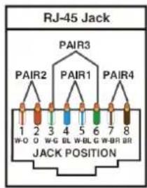
| Data Link TIA/EIA-568-B | ||
| PIN | Color | Function |
| 1 | TX0- | |
| 2 | TX0+ | |
| 3 | TX1- | |
| 4 | TX2- | |
| 5 | TX2+ | |
| 6 | TX1+ | |
| 7 | TXC- | |
| 8 | TXC+ | |
NOTE
The QUALITY and TRANSMISSION of the video signals depends on the characteristics and quality of the UTP cables. Higher resolutions and longer transmission distances require low skew cables (<25ns/up to 300m) for best performance.
Unshielded CAT6 with metal RJ-45 connectors is recommended.

NOTICE
- All HDMI over UTP transmission distances are measured using Belden CAT6A (625MHz), 4-Pair, U/UTP-Unshielded, Riser-CMR, Premise Horizontal Cable, 23 AWG Solid Bare Copper Conductors, Polyolefin Insulation, Patented Double-H spline, Ripcord, PVC Jacket using Quantum980 signal HDMI Video Generator Module Video Pattern Testing.
- The transmission length is largely affected by the type of category cables, also the type of HDMI sources, and the type of HDMI display. The testing result shows solid UTP cables (usually in the form of 300m or 1000ft bulk cable) can transmit a lot longer signals than stranded UTP cables (usually in the form of patch cords). Shielded STP connectors are better suit than unshielded UTP connectors. A solid UTP CAT5e cable shows longer transmission length than stranded STP CAT6 cable. For long extension users, solid cables are your only choice.
- EIA/TIA-568-B termination (T568B) for category cables is recommended for better performance.
- To reduce the interference among the unshielded twisted pairs of wires in category cable, you can use shielded STP cables with shielded connector to improve EMI problems, which occurs in long transmission.
- Because the quality of the category cables has the major effects in how long transmission distance will be made and how good is the received display, the actual transmission length is subject to your category cables. For resolution greater than 1080i or 1280x1024, a solid CAT6 cable is the only viable choice.
PERFORMANCE GUIDE FOR HDMI OVER CATEGORY CABLE TRANSMISSION
| PERFORMANCE RATING | TYPE OF CATEGORY CABLE | |||
| WIRING | SHIELDING | CAT5e | CAT6 | CAT6A/7 |
| SOLID | UNSHIELDED (UTP) | ★★★★ | ★★★★★ | ★★★★★ |
| SHIELDED (STP) | ★★★ | ★★★★ | ★★★★ | |
| STRANDED | UNSHIELDED (UTP) | ★ | ★★ | ★★ |
| SHIELDED (STP) | ★★ | ★ | ★★ | |
| TERMINATION | PLEASE USE EIA/TIA-568-B TERMINATION (T568B) AT ANY TIME | |||
Avenview Warranty Certificate
AVENVIEW CORP. ("Avenview") warrants Avenview-branded product(s) contained in the original packaging against defects in materials and workmanship when used normally in accordance with Avenview's enclosed manual guidelines for a period of THREE (3) YEARS from the date of original retail purchase - Warranty Period. Avenview's published guidelines include but are not limited to information contained in technical specifications, user manuals and service communications.
LABOR: During the Warranty Period of THREE (3) YEARS, Avenview will repair or replace the product(s) at no cost using new or used parts equivalent to novel performance and reliability if the product(s) is determined to have abide by Avenview's published guidelines. Cost of Labor applicable to product(s) after Warranty Period. For labor costs, please contact support@avenview.com.
PARTS: During the Warranty Period of of THREE (3) YEARS, Avenview will supply new or rebuilt replacements in exchange for defective parts of the product(s) at no cost if the product(s) is determined to have abide by Avenview's published guidelines. Cost of Parts applicable to product(s) after Warranty Period. For part(s) costs, please contact support@avenview.com.
To obtain Warranty: (a) proof of purchase in the form of a bill of sale or receipted invoice reflecting that the registered product(s) is within warranty period must be presented to obtain warranty service; (b) product(s) must be registered at time of purchase. Failure to do so will result in applicable parts and labor charges. Returning product(s) must be shipped in Avenview's original packaging or in packaging pertaining equal degree of protection to Avenview's. Both Avenview and purchaser are responsible for freight charges and brokerages when shipping the product(s) to the receiver.
NOT COVERED BY THIS WARRANTY
This warranty does not apply to any non-Avenview branded product(s); non-registered Avenview product(s). This warranty does not apply: (a) to cosmetic damage, including but not limited to scratches, dents and broken cords; (b) to damage caused by use with another product; (c) to damage caused by accident, abuse, misuse, liquid contact, fire, earthquake or other external cause; (d) to damage caused by operating the Avenview product(s) outside Avenview's manuals or guidelines; (e) to damage caused by service performed by anyone who is not a representative of Avenview or an Avenview authorized personnel; (f) to defects caused by normal wear and tear or otherwise due to the normal aging of the Avenview product(s), or (g) if any serial number has been removed or defaced from the Avenview product(s).
AVENVIEW IS NOT LIABLE FOR DIRECT, SPECIAL, INCIDENTAL OR CONSEQUENTIAL DAMAGES RESULTING FROM ANY BREACH OF WARRANTY OR CONDITION, OR UNDER ANY OTHER LEGAL THEORY, INCLUDING BUT NOT LIMITED TO LOSS OF USE; LOSS OF REVENUE; LOSS OF ACTUAL OR ANTICIPATED PROFITS (INCLUDING LOSS OF PROFITS ON CONTRACTS); LOSS OF THE USE OF MONEY; LOSS OF ANTICIPATED SAVINGS; LOSS OF BUSINESS; LOSS OF OPPORTUNITY; LOSS OF GOODWILL; LOSS OF REPUTATION; LOSS OF, DAMAGE TO, COMPROMISE OR CORRUPTION OF DATA; OR ANY INDIRECT OR CONSEQUENTIAL LOSS OR DAMAGE REPAIR OR REPLACEMENT AS PROVIDED UNDER THIS WARRANTY IS THE EXCLUSIVE REMEDY OF THE CONSUMER.
Some states do not allow the inclusion or limitation of incidental or consequential damages, or allow limitations on duration implements of the Warranty Period; therefore the above limitations or exclusions may not be applicable to you. This warranty gives you specific legal rights, and you may have other rights which vary from state to state.
275 Woodward Avenue, Kenmore, NY 14217 1.866.508.0269

TECHNICAL SUPPORT
CONTACT US

Phone: I (866) 508 0269

Email: support@avenview.com

natural_image
Illustration of a globe with a headset, symbolizing global communication or internet (no text or symbols present)USA Head Office Avenview Corp. 275 Woodward Avenue Kenmore, NY 14217
USA Head Office
Office Avenview Corp.
275 Woodward Avenue
Kenmore, NY14217
Phone: +1.716.218.4100
Fax: +1.866.387-8764
Email: info@avenview.com
Canada Sales
Avenview
151 Esna Park Drive, Units 11 & 12
Markham, Ontario, L3R3BI
Phone: 1.905.907.0525
Fax: 1.866.387.8764
Email: info@avenview.com
Avenview Europe
Avenview Europe
Demkaweg 11
3555 HW Utrecht
Netherlands
Phone: +31(0)85 2100 613
Unit 8, 6/f., Kwai Cheong Centre,
50 Kwai Cheong Road,
Kwai Chung, N.T.
Hong kong
Phone: 852.3575.9585
Email: wenxi@avenview.com
Disclaimer
While every precaution has been taken in the preparation of this document, Avenview Inc. assumes no liability with respect to the operation or use of Avenview hardware, software or other products and documentation described herein, for any act or omission of Avenview concerning such products or this documentation, for any interruption of service, loss or interruption of business, loss of anticipatory profits, or for punitive, incidental or consequential damages in connection with the furnishing, performance, or use of the Avenview hardware, software, or other products and documentation provided herein.
Avenview Inc. reserves the right to make changes without further notice to a product or system described herein to improve reliability, function or design. With respect to Avenview products which this document relates, Avenview disclaims all express or implied warranties regarding such products, including but not limited to, the implied warranties of merchantability, fitness for a particular purpose, and non-infringement.


- Display Videowall Processor with Rotation
- Product Application & Market Sectors
- TABLE OF CONTENTS
- I.1 IMPORTANT SAFEGUARDS
- What the warranty does not cover
- SAFETY INSTRUCTIONS
- REGULATORY NOTICES FEDERAL COMMUNICATIONS COMMISSION (FCC)
- Warning Symbols
- Description
- WARNING
- INTRODUCTION
- FEATURES
- PACKAGE CONTENTS
- BEFORE INSTALLATION
- CABLE SPECIFICATIONS
- FEATURES:
- INSTALLATION (DVI-PROWALL-12X)
- GENERAL INSTRUCTIONS
- DVI-PROWALL-12X
- PANEL DESCRIPTION
- FRONT PANEL (DVI-PROWALL-I2X)
- REAR PANEL (DVI-PROWALL-12X)
- SUPPORTED RESOLUTION
- SOFTWARE OPERATION
- System Requirement and Precautions
- Start the software control program
- Control Interface
- Display mode
- Input Rotation
- Output Control
- Output Resolution
- Display setting
- Customize
- Quick Select
- (3) Contrast/Brightness
- Advancing setting
- File Options
- Learn EDID
- Info
- Refresh
- EDID LEARNING
- WARRANTY WILL NOT COVER THE DAMAGE
- NOTE
- NOTICE
- Avenview Warranty Certificate
- NOT COVERED BY THIS WARRANTY
- TECHNICAL SUPPORT
- CONTACT US
- USA Head Office
- Canada Sales
- Avenview Europe
- Disclaimer
Brand : Avenview
Model : DVI-PROWALL-12X
Category : Uncategorized