
H262-Z6B - Uncategorized GIGABYTE - Free user manual and instructions
Find the device manual for free H262-Z6B GIGABYTE in PDF.


| Product Type | Server Motherboard |
| Form Factor | E-ATX |
| CPU Socket | Dual LGA 4094 (SP3) |
| Supported CPUs | AMD EPYC 7002/7003 Series |
| Memory | 32 DIMM Slots, DDR4 ECC Registered |
| Max Memory Capacity | 2 TB (with 64GB DIMMs) |
| Expansion Slots | 7x PCIe 4.0 x16 Slots |
| Storage Interfaces | 2x M.2 (NVMe/SATA), 8x SATA3 |
| Network | Dual 10GBase-T LAN (Intel X710) |
| Management | BMC with IPMI 2.0 |
| USB Ports | 2x USB 3.2 Gen1 (Rear), 2x USB 2.0 (Header) |
| Power Connectors | 24-pin ATX, 2x 8-pin EPS |
| Dimensions | 12" x 13" (304.8 x 330.2 mm) |
| Weight | 1.7 kg (3.75 lbs) |
| Operating Temperature | 0°C to 40°C (32°F to 104°F) |
| Certifications | CE, FCC, RoHS |
Frequently Asked Questions - H262-Z6B GIGABYTE
User questions about H262-Z6B GIGABYTE
0 question about this device. Answer the ones you know or ask your own.
Ask a new question about this device
Download the instructions for your Uncategorized in PDF format for free! Find your manual H262-Z6B - GIGABYTE and take your electronic device back in hand. On this page are published all the documents necessary for the use of your device. H262-Z6B by GIGABYTE.
USER MANUAL H262-Z6B GIGABYTE
© 2021 GIGA-BYTE TECHNOLOGY CO., LTD. All rights reserved.
The trademarks mentioned in this manual are legally registered to their respective owners.
Disclaimer
Information in this manual is protected by copyright laws and is the property of GIGABYTE.
Changes to the specifications and features in this manual may be made by GIGABYTE without prior notice. No part of this manual may be reproduced, copied, translated, transmitted, or published in any form or by any means without GIGABYTE's prior written permission.
Documentation Classifications
In order to assist in the use of this product, GIGABYTE provides the following types of documentation:
■ User Manual: detailed information & steps about the installation, configuration and use this product (motherboard), covering hardware & BIOS
■ Service Guide: detailed information & steps about the installation, configuration and use of this product (server barebones), covering hardware & BIOS
■ User Guide: information about a particular firmware or software package that can be used with this product (such as BMC firmware)
■ Quick Installation Guide: a short guide with visual diagrams that you can reference easily for installation purposes
Please see the support section of the online product page to check the current availability of these documents
For More Information
For related product specifications, the latest firmware and software, and related information, please visit our website at:
http://www.gigabyte.com
For GIGABYTE distributors and resellers, additional sales & marketing materials are available from our re-seller portal:
http://reseller.b2b.gigabyte.com
Conventions
The following conventions are used in this user's guide:
 | NOTE!Pieces of additionalinformation related to the current topic. |
 | CAUTION!Precautionary measures toavoid possible hardware or software problems. |
 | WARNING!Alerts to any damage that mightresult from doing or not doing specific actions. |
Server Warnings and Cautions
Before installing a server, be sure that you understand the following warnings and cautions.

WARNING!
To reduce the risk of electric shock or damage to the equipment:
- Do not disable the power cord grounding plug. The grounding plug is an important safety feature.
- Plug the power cord into a grounded (earthed) electrical outlet that is easily accessible at all times.
- Unplug all the power cords from the power supplies to disconnect power to the equipment.


- Shock Hazard! Disconnect all power supply cords before servicing.
- Do not route the power cord where it can be walked on or pinched by items placed against it. Pay particular attention to the plug, electrical outlet, and the point where the cord extends from the server.

WARNING!
To reduce the risk of personal injury from hot surfaces, allow the drives and the internal system components to cool before touching them.

WARNING!
This server is equipped with high speed fans. Keep away from hazardous moving fan blades during servicing.

WARNING!
This equipment is not suitable for use in locations where children are likely to be present.

WARNING!
This equipment is intended to be used in Restrict Access Location. The access can only be gained by Skilled person.
Only authorized by well trained professional person can access the restrict access location.

CAUTION!
- Do not operate the server for long periods with the access panel open or removed.
Operating the server in this manner results in improper airflow and improper cooling that can lead to thermal damage. - Danger of explosion if battery is incorrectly replaced.
- Replace only with the same or equivalent type recommended by the manufacturer.
- Dispose of used batteries according to the manufacturer's instructions.
Electrostatic Discharge (ESD)

CAUTION!
ESD CAN DAMAGE DRIVES, BOARDS, AND OTHER PARTS. WE RECOMMEND THAT YOU PERFORM ALL PROCEDURES AT AN ESD WORKSTATION. IF ONE IS NOT AVAILABLE, PROVIDE SOME ESD PROTECTION BY WEARING AN ANTI-STATIC WRIST STRAP ATTACHED TO CHASSIS GROUND -- ANY UNPAINTED METAL SURFACE -- ON YOUR SERVER WHEN HANDLING PARTS.
Always handle boards carefully, they can be extremely sensitive to ESD. Hold boards only by their edges without touching any components or connectors. After removing a board from its protective ESD bag or from the system, place the board component side up on a grounded, static free surface. Use a conductive foam pad if available but not the ESD bag. Do not slide the board over any surface.
System power on/off: To service components within the server, please ensure the power has been disconnected.
e.g. Remove the node from the server chassis (to disconnect power) or disconnect the power from the server chassis.
Make sure the system is removed from the rack before opening the chassis, adding, or removing any non hot-plug components.
Hazardous conditions, devices and cables: Hazardous electrical conditions may be present on power, telephone, and communication cables. Turn off the system chassis and disconnect the cables attached to the system before servicing the chassis. Otherwise, personal injury or equipment damage can result.
Electrostatic discharge (ESD) and ESD protection: ESD can damage drives, boards, and other parts. We recommend that you perform all procedures in this chapter only at an ESD workstation. If one is not available, provide some ESD protection by wearing an antistatic wrist strap attached to chassis ground (any unpainted metal surface on the server) when handling parts.
ESD and handling boards: Always handle boards carefully. They can be extremely sensitive to electrostatic discharge (ESD). Hold boards only by their edges. After removing a board from its protective wrapper or from the system, place the board component side up on a grounded, static free surface. Use a conductive foam pad if available but not the board wrapper. Do not slide board over any surface.
Installing or removing jumpers: A jumper is a small plastic encased conductor that slips over two jumper pins. Some jumpers have a small tab on top that can be gripped with fin-gertips or with a pair of fine needle nosed pliers. If the jumpers do not have such a tab, take care when using needle nosed pliers to remove or install a jumper; grip the narrow sides of the jumper with the pliers, never the wide sides. Gripping the wide sides can dam-age the contacts inside the jumper, causing intermittent problems with the function con-trolled by that jumper. Take care to grip with, but not squeeze, the pliers or other tool used to remove a jumper, or the pins on the board may bend or break.
Table of Contents
Chapter 1 Hardware Installation ...... 11
1-1 Installation Precautions.... 11
1-2 Product Specifications.... 12
1-3 System Block Diagram.... 18
Chapter 2 System Appearance....17
2-1 Front View....17
2-2 Rear View....18
2-3 Front Panel LED and Buttons 19
2-4 RoT LEDs....20
2-5 Rear System LAN LEDs....22
2-6 Power Supply Unit LED....23
2-7 Hard Disk Drive LEDs 24
Chapter 3 System Hardware Installation ....25
3-1 Installing the Hard Disk Drive....26
3-2 Removing the Node 27
3-3 Removing Chassis Cover....28
3-4 Removing and Installing the Fan Duct 29
3-5 Removing and Installing the Heatsink.... 30
3-6 Installing the CPU 32
3-7 Installing Memory 33
3-7-1 Eight Channel Memory Configuration....33
3-7-2 Installing the Memory 34
3-7-3 Processor and Memory Module Matrix Table 34
3-7-4 Memory Population Table 35
3-8 Installing the PCI Expansion Card 36
3-9 Installing the Mezzanine Card.... 38
3-9-1 Installing the OCP 3.0 Mezzanine Card ....38
3-10 Replacing the Fan Assembly.... 39
3-11 Replacing the Power Supply 40
3-12 Replacing Power Distribution Board Cage 41
3-13 Cable Routing 42
3-13-1 H262-Z6A 42
3-13-2 H262-Z6B 51
Chapter 4 Motherboard Components ....57
4-1 Motherboard Components 57
4-2 Jumper Setting 58
Chapter 5 BIOS Setup ....59
5-1 The Main Menu 61
5-2 Advanced Menu 63
5-2-1 Trusted Computing 65
5-2-2 PSP Firmware Versions....66
5-2-3 Legacy Video Select....67
5-2-4 AST2500 Super IO Configuration....68
5-2-5 S5 RTC Wake Settings....71
5-2-6 Serial Port Console Redirection 72
5-2-7 CPU Configuration....76
5-2-8 PCI Subsystem Settings....77
5-2-9 USB Configuration....79
5-2-10 Network Stack Configuration....81
5-2-11 NVMe Configuration 82
5-2-12 SATA Configuration....83
5-2-13 UEFI POST LOGO Configuration....84
5-2-14 AMD Mem Configuration Status....85
5-2-15 Tls Auth Configuration 86
5-2-16 Intel(R) Ethernet Controller I350....87
5-2-17 VLAN Configuration....89
5-2-18 MAC IPv4 Network Configuration....90
5-2-19 MAC IPv6 Network Configuration....91
5-3 AMD CBS Menu....92
5-3-1 CPU Common Options....93
5-3-2 DF Common Options....98
5-3-3 UMC Common Options 103
5-3-4 NBIO Common Options....117
5-3-5 FCH Common Options 123
5-3-6 NTB Common Options 127
5-3-7 SOC Miscellaneous Control 128
5-3-8 Workload Tuning....129
5-4 AMD PBS Menu 130
5-4-1 RAS....131
5-5 Chipset Setup Menu....133
5-5-1 North Bridge 134
5-5-2 Fabric Resource 135
5-6 Server Management Menu....136
5-6-1 System Event Log 138
5-6-2 View FRU Information 139
5-6-3 BMC Network Configuration....140
5-6-4 IPv6 BMC Network Configuration....141
5-7 Security Menu 142
5-7-1 Secure Boot 143
5-8 Boot Menu....145
5-8-1 UEFI NETWORK Drive BBS Priorities 147
5-8-2 UEFI Application Boot Priorities 148
5-9 Save & Exit Menu.... 149
5-10 BIOS POST Beep code (AMI standard).... 150
5-10-1 PEI Beep Codes....150
5-10-2 DXE Beep Codes ....150
This page intentionally left blank
Chapter 1 Hardware Installation
1-1 Installation Precautions
The motherboard/system contain numerous delicate electronic circuits and components which can become damaged as a result of electrostatic discharge (ESD). Prior to installation, carefully read the user manual and follow these procedures:
- Prior to installation, do not remove or break motherboard S/N (Serial Number) sticker or warranty sticker provided by your dealer. These stickers are required for warranty validation.
- Always remove the AC power by unplugging the power cord from the power outlet before installing or removing the motherboard or other hardware components.
- When connecting hardware components to the internal connectors on the motherboard, make sure they are connected tightly and securely.
- When handling the motherboard, avoid touching any metal leads or connectors.
- It is best to wear an electrostatic discharge (ESD) wrist strap when handling electronic components such as a motherboard, CPU or memory. If you do not have an ESD wrist strap, keep your hands dry and first touch a metal object to eliminate static electricity.
- Prior to installing the motherboard, please have it on top of an antistatic pad or within an electrostatic shielding container.
- Before unplugging the power supply cable from the motherboard, make sure the power supply has been turned off.
- Before turning on the power, make sure the power supply voltage has been set according to the local voltage standard.
- Before using the product, please verify that all cables and power connectors of your hardware components are connected.
- To prevent damage to the motherboard, do not allow screws to come in contact with the motherboard circuit or its components.
- Make sure there are no leftover screws or metal components placed on the motherboard or within the computer casing.
- Do not place the computer system on an uneven surface
- Do not place the computer system in a high-temperature environment.
- Turning on the computer power during the installation process can lead to damage to system components as well as physical harm to the user.
- If you are uncertain about any installation steps or have a problem related to the use of the product, please consult a certified computer technician.
1-2 Product Specifications

NOTE:
We reserve the right to make any changes to the product specifications and product-related information without prior notice.

CPU (H262-Z6A)
AMD EPYC™ 7003 series processor family
Dual processors, 7nm technology
◆ Up to 64-core, 128 threads per processor
◆ TDP up to 200W
NOTE:
- If only 1 CPU is installed, some PCIe or memory functions might be unavailable
- Contact GIGABYTE sales rep or technical support for more details about supporting cTDP 240W CPU
Compatible with AMD EPYC™ 7002 series processor family
(H262-Z6B)
AMD EPYC™ 7003 series processor family
◆ Dual processors, 7nm technology
◆ Up to 64-core, 128 threads per processor
◆ TDP up to 225W, cTDP up to 240W
Conditional support 280W
NOTE:
- If only 1 CPU is installed, some PCIe or memory functions might be unavailable
- Contact GIGABYTE sales rep or technical support for more details about supporting 240W - 280W CPU
Compatible with AMD EPYC™ 7002 series processor family

Socket Per Node:
2 x LGA 4094
Total:
8 x LGA 4094
- Socket SP3

Chipset ♦ System on Chip (SoC)

Hardware-Level
Root of Trust Support
- Supported
NOTE! The system will take extra time to boot as it goes through RoT authentication.

Memory Per Node:
◆ 16 x DIMM slots
Total:
◆ 64 x DIMM slots
DDR4 memory supported only
◆ 8-Channel memory per processor architecture
◆ RDIMM modules up to 128GB supported
♦ LRDIMM modules up to 128GB supported
◆ Memory speed: Up to 3200 MHz

LAN Per Node:
◆ 2 x 1GbE LAN ports (1 x Intel® I350-AM2)
◆ 1 x Dedicated management port
Per Node:
◆ 8 x 1GbE LAN ports (1 x Intel® I350-AM2)
◆ 4 x Dedicated management ports
◆ 1 x 10/100/1000 *CMC global management port
*CMC: Chassis Management Controller, to monitor all status of computing nodes

Video ♦ Integrated in Aspeed® AST2500
◆ 2D Video Graphic Adapter with PCIe bus interface
◆ 1920x1200@60Hz 32bpp, DDR4 SDRAM
Management chip on CMC board:
♦ Integrated in Aspeed® AST2520A2-GP

Storage (H262-Z6A)
Per node:
◆ 6 x 2.5" Gen4 U.2 hot-swappable SSD bays
1 x M.2 slot from CPU_0:
M-key
PCIe Gen4 x4
◆ Supports NGFF-2280/22110 cards
Total:
◆ 24 x 2.5" Gen4 U.2 hot-swappable SSD bays
All storage bays are compatible with SATA devices
4 x M.2 slots from CPU_0:
M-key
PCIe Gen4 x4
◆ Supports NGFF-2280/22110 cards
(H262-Z6B) Per node:
◆ 2 x 2.5" Gen4 U.2 hot-swappable SSD bays
1 x M.2 slot from CPU_0:
M-key
PCIe Gen4 x4
◆ Supports NGFF-2280/22110 cards
Total:
◆ 8 x 2.5" Gen4 U.2 hot-swappable SSD bays
All storage bays are compatible with SATA devices
4 x M.2 slots from CPU_0:
M-key
PCIe Gen4 x4
◆ Supports NGFF-2280/22110 cards

Expansion Slots Per node:
◆ 2 x Low profile half-length slots with PCIe x16 (Gen4 x16 bus) from CPU_0
◆ 1 x OCP 3.0 mezzanine slot with PCIe Gen4 x16 bandwidth
Total:
8 x Low profile half-length slots with PCIe x16 (Gen4 x16 bus) from CPU_0
◆ 4 x OCP 3.0 mezzanine slot with PCIe Gen4 x16 bandwidth

Internal I/O Per Node:
◆ 1 x M.2 slot
◆ 1 x COM header
◆ 1 x TPM header
◆ 1 x BMC SGPIO header
◆ 1 x JTAG BMC header
◆ 1 x PLD header
◆ 1 x Clear CMOS jumper
◆ 1 x IPMB connector

Front I/O Per node:
◆ 1 x Power button with LED
◆ 1 x ID button with LED
◆ 1 x Status LED
◆ 1 x System reset button
Total:
◆ 4 x Power button with LED
◆ 4 x ID button with LED
◆ 4 x Status LED
◆ 4 x System reset button
*1 x CMC status LED
*1 x CMC reset button
*Only one CMC status LED per system

Rear I/O Per node:
◆ 2 x USB 3.0
◆ 1 x Mini-DP
◆ 2 x RJ45
◆ 1 x RJ45 MLAN
◆ 1 x ID LED
Total:
8 x USB 3.0
4 x Mini-DP
8 x RJ45
◆ 4 x RJ45 MLAN
◆ 4 x ID LED
*1 x CMC global management port
*Only one CMC status LED per system

Backplane I/O (H262-Z6A)
24 x ports
Speed and bandwidth: SATA 6Gb/s or SAS 12Gb/s or PCIe Gen4 x4 per port
(H262-Z6B)
8 x ports
Speed and bandwidth: SATA 6Gb/s or SAS 12Gb/s or PCIe Gen4 x4 per port
| TPM ◆ 1 x TPM header with SPI interface◆ Optional TPM2.0 kit: CTM010 | |
| System Management | ◆ Aspeed® AST2500 management controller◆ GIGABYTE Management Console (AMI MegaRAC SP-X) web interface◆ Dashboard◆ JAVA Based Serial Over LAN◆ HTML5 KVM◆ Sensor Monitor (Voltage, RPM, Temperature, CPU Status ...etc.)◆ Sensor Reading History Data◆ FRU Information◆ SEL Log in Linear Storage / Circular Storage Policy◆ Hardware Inventory◆ Fan Profile◆ System Firewall◆ Power Consumption◆ Power Control◆ LDAP / AD / RADIUS Support◆ Backup & Restore Configuration◆ Remote BIOS/BMC/CPLD Update◆ Event Log Filter◆ User Management◆ Media Redirection Settings◆ PAM Order Settings◆ SSL Settings◆ SMTP Settings |
| Power Supply ◆ 21 x 2200W redundant PSUs◆ 80 PLUS Platinum◆ AC Input:- 100-127V~/ 14A, 47-63Hz- 200-240V~/ 12.6A, 47-63Hz◆ DC Output:- Max 1200W/ 100-127V~+12.12V/ 95.6A+12Vsb/ 3.5A- Max 2200W/ 200-240V+12.12V/ 178.1A+12Vsb/ 3.5A | |

Ambient
Temperature
♦ Operating temperature: 10°C to 35°C
◆ Operating humidity: 8-80% (non-condensing)
Relative
Humidity
Non-operating temperature: -40°C to 60°C
Non-operating humidity: 20%-95% (non-condensing)

System
Dimension
◆ 2U 4 Nodes - Rear access
◆ 440 (W) x 87 (H)x 840 (D) mm
1-3 System Block Diagram
H262-Z6A

flowchart
graph TD
    subgraph_CPU_0["CPU_0"]
        A["AMD EPYC"] -->|SATAIIE x6| B["5x SATA BTB Conn."]
        B --> C["OCP 3.0 Mezzanine"]
        C --> D["PCIe3.0 x2"]
        D --> E["Intel i350"]
        E --> F["NOSI"]
        F --> G["Switch"]
        G --> H["PCIe4.0 x16"]
        H --> I["PCIe4.0 x16"]
        I --> J["PCIe4.0 x16"]
        J --> K["PCIe4.0 x16"]
        K --> L["PCIe4.0 x16"]
        L --> M["PCIe4.0 x16"]
        M --> N["PCIe4.0 x16"]
        N --> O["PCIe4.0 x16"]
    end

    subgraph_CPU_1["CPU_1"]
        P["AMD EPYC"] --> Q["Up to 3200 MHz"]
        P --> R["8-Channel DDR4 1DPC"]
        P --> S["8-Channel DDR4 1DPC"]
        T["PCIe4.0 x8"] --> U["PCIe4.0 x8"]
        U --> V["PCIe4.0 x16"]
        W["PCIe4.0 x16"] --> X["PCIe4.0 x16"]
        X --> Y["PCIe4.0 x16"]
        Y --> Z["PCIe4.0 x16"]
        Z --> AA["PCIe4.0 x16"]
        AA --> AB["PCIe4.0 x16"]
        AB --> AC["PCIe4.0 x16"]
        AC --> AD["PCIe4.0 x16"]
        AD --> AE["PCIe4.0 x16"]
        AE --> AF["PCIe4.0 x16"]
        AF --> AG["PCIe4.0 x16"]
        AG --> AH["PCIe4.0 x16"]
        AH --> AI["PCIe4.0 x16"]
        AI --> AJ["PCIe4.0 x16"]
        AJ --> AK["PCIe4.0 x16"]
        AK --> AL["PCIe4.0 x16"]
        AL --> AM["PCIe4.0 x16"]
        AM --> AN["PCIe4.0 x16"]
        AN --> AO["PCIe4.0 x16"]
        AO --> AP["PCIe4.0 x16"]
        AP --> AQ["PCIe4.0 x16"]
        AQ --> AR["PCIe4.0 x16"]
        AR --> AS["PCIe4.0 x16"]
        AS --> AT["PCIe4.0 x16"]
        AT --> AU["PCIe4.0 x16"]
        AU --> AV["PCIe4.0 x16"]
        AV --> AW["PCIe4.0 x16"]
        AW --> AX["PCIe4.0 x16"]
        AX --> AY["PCIe4.0 x16"]
        AY --> AZ["PCIe4.0 x16"]
        AZ --> BA["PCIe4.0 x16"]
        BA --> BB["PCIe4.0 x16"]
        BB --> BC["PCIe4.0 x16"]
        BC --> BD["PCIe4.0 x16"]
        BD --> BE["PCIe4.0 x16"]
        BE --> BF["PCIe4.0 x16"]
        BF --> BG["PCIe4.0 x16"]
        BG --> BH["PCIe4.0 x16"]
        BH --> BI["PCIe4.0 x16"]
        BI --> BJ["PCIe4.0 x16"]
        BJ --> BK["PCIe4.0 x16"]
        BK --> BL["PCIe4.0 x16"]
        BL --> BM["PCIe4.0 x16"]
        BM --> BN["PCIe4.0 x16"]
        BN --> BO["PCIe4.0 x16"]
        BO --> BP["PCIe4.0 x16"]
        BP --> BQ["PCIe4.0 x16"]
        BQ --> BR["PCIe4.0 x16"]
        BR --> BS["PCIe4.0 x16"]
        BS --> BT["PCIe4.0 x16"]
        BT --> BU["PCIe4.0 x16"]
        BU --> BV["PCIe4.0 x16"]
        BV --> BW["PCIe4.0 x16"]
        BW --> BX["PCIe4.0 x16"]
        BX --> BY["PCIe4.0 x16"]
        BY --> BZ["PCIe4.0 x16"]
        BZ --> CA["PCIe4.0 x16"]
        CA --> CB["PCIe4.0 x16"]
        CB --> CC["PCIe4.0 x16"]
        CC --> CD["PCIe4.0 x16"]
        CD --> CE["PCIe4.0 x16"]
        CE --> CF["PCIe4.0 x16"]
    end

    subgraph CPU_2
        GPT["PLOT"] --> GPTA["TOPM"]
    end

    subgraph CPU_3
        GPTA --> GPTB["TOPM"]
    end

    subgraph CPU_4
        GPTB --> GPTC["TOPM"]
    end

    subgraph CPU_5
        GPTC --> GPTD["TOPM"]
    end

    subgraph CPU_6
        GPTD --> GPTE["TOPM"]
    end

    subgraph CPU_7
        GPTE --> GPTF["TOPM"]
    end

    subgraph CPU_8
        GPTF --> GPTG["TOPM"]
    end

    subgraph CPU_9
        GPTG --> GPTH["TOPM"]
    end

    subgraph CPU_10
        GPTH --> GPTI["TOPM"]
    end

    subgraph CPU_11
        GPTI --> GPTJ["TOPM"]
    end

    subgraph CPU_12
        GPTJ --> GPTK["TOPM"]
    end

    subgraph CPU_13
        GPTK --> GPTL["TOPM"]
    end

    subgraph CPU_14
        GPTL --> GPTM["TOPM"]
    end

    subgraph CPU_15
        GPTM --> GPTN["TOPM"]
    end

    subgraph CPU_16
        GPTN --> GPTO["TOPM"]
    end

    subgraph CPU_17
        GPTO --> GPTP["TOPM"]
    end

    subgraph CPU_18
        GPTP --> GPTQ["TOPM"]
    end

    subgraph CPU_19
        GPTQ --> GPTR["TOPM"]
    end

    subgraph CPU_20
        GPTR --> GPTS["TOPM"]
    end

    subgraph CPU_21
        GPTS --> GPTU["TOPM"]
    end

    subgraph CPU_22
        GPTU --> GPTV["TOPM"]
    end

    subgraph CPU_23
        GPTV --> GPTW["TOPM"]
    end

    subgraph CPU_24
        GPTW --> GPTX["TOPM"]
    end

    subgraph CPU_25
        GPTX --> GPTY["TOPM"]
    end

    subgraph CPU_26
        GPTY --> GPTZ["TOPM"]
    end

    subgraph CPU_27
        GPTZ --> GPTA["TOPM"]
    end

    subgraph CPU_28
        GPTA --> GPTU["TOPM"]
    end

    subgraph CPU_29
        GPTU --> GPTV["TOPM"]
    end

    subgraph CPU_30
        GPTV --> GPTU["TOPM"]
    end

    subgraph CPU_31
        GPTU --> GPTV["TOPM"]
    end

    subgraph CPU_32
        GPTU --> GPTV["TOPM"]

    note left of A: AMD MILAN "Zen3" Core Sockets SP3
    note right of B: AMD MILAN "Zen3" Core Sockets SP3
H262-Z6B

flowchart
graph TD
    subgraph_CPU_0["CPU_0"]
        A["AMD EPYC AMD MILAN "Zen3" Core Sockets SP3"] -->|SATAIIF x6| B["SlimLine"]
        B --> C["6 x SATA BTB Conn."]
        C --> D["OCP 3.0 Mezzanine"]
    end

    subgraph_CPU_1["CPU_1"]
        E["AMD EPYC AMD MILAN "Zen3" Core Sockets SP3"] --> F["SLOT_R: GEN-Z 4C_R"]
        F --> G["SLOT_L: GEN-Z 2C_L"]
        G --> H["2 x U2 BTB Conn."]
        H --> I["COM"]
        H --> J["Mini-DP"]
        H --> K["MLAN"]
        H --> L["To CMC"]
    end

    A -->|PCIe4.0 x16| M["PCIe3.0 x2"]
    A -->|PCIe4.0 x16| N["PCIe3.0 x2"]
    A -->|PCIe4.0 x16| O["PCIe3.0 x2"]
    A -->|PCIe4.0 x16| P["PCIe3.0 x2"]
    A -->|PCIe4.0 x16| Q["PCIe3.0 x2"]
    A -->|PCIe4.0 x16| R["PCIe3.0 x2"]
    A -->|PCIe4.0 x16| S["PCIe3.0 x2"]
    A -->|PCIe4.0 x16| T["PCIe3.0 x2"]
    A -->|PCIe4.0 x16| U["PCIe3.0 x2"]
    A -->|PCIe4.0 x16| V["PCIe3.0 x2"]
    A -->|PCIe4.0 x16| W["PCIe3.0 x2"]
    A -->|PCIe4.0 x16| X["PCIe3.0 x2"]
    A -->|PCIe4.0 x16| Y["PCIe3.0 x2"]
    A -->|PCIe4.0 x16| Z["PCIe3.0 x2"]
    A -->|PCIe4.0 x16| AA["PCIe3.0 x2"]
    A -->|PCIe4.0 x16| AB["PCIe3.0 x2"]
    A -->|PCIe4.0 x16| AC["PCIe3.0 x2"]
    A -->|PCIe4.0 x16| AD["PCIe3.0 x2"]
    A -->|PCIe4.0 x16| AE["PCIe3.0 x2"]
    A -->|PCIe4.0 x16| AF["PCIe3.0 x2"]
    A -->|PCIe4.0 x16| AG["PCIe3.0 x2"]
    A -->|PCIe4.0 x16| AH["PCIe3.0 x2"]
    A -->|PCIe4.0 x16| AI["PCIe3.0 x2"]
    A -->|PCIe4.0 x16| AJ["PCIe3.0 x2"]
    A -->|PCIe4.0 x16| AK["PCIe3.0 x2"]
    A -->|PCIe4.0 x16| AL["PCIe3.0 x2"]
    A -->|PCIe4.0 x16| AM["PCIe3.0 x2"]
    A -->|PCIe4.0 x16| AN["PCIe3.0 x2"]
    A -->|PCIe4.0 x16| AO["PCIe3.0 x2"]
    A -->|PCIe4.0 x16| AP["PCIe3.0 x2"]
    A -->|PCIe4.0 x16| AQ["PCIe3.0 x2"]
    A -->|PCIe4.0 x16| AR["PCIe3.0 x2"]
    A -->|PCIe4.0 x16| AS["PCIe3.0 x2"]
    A -->|PCIe4.0 x16| AT["PCIe3.0 x2"]
    A -->|PCIe4.0 x16| AU["PCIe3.0 x2"]
    A -->|PCIe4.0 x16| AV["PCIe3.0 x2"]
    A -->|PCIe4.0 x16| AW["PCIe3.0 x2"]
    A -->|PCIe4.0 x16| AX["PCIe3.0 x2"]
    A -->|PCIe4.0 x16| AY["PCIe3.0 x2"]
    A -->|PCIe4.0 x16| AZ["PCIe3.0 x2"]
    A -->|PCIe4.0 x16| BA["PCIe3.0 x2"]
    A -->|PCIe4.0 x16| BB["PCIe3.0 x2"]
    A -->|PCIe4.0 x16| BC["PCIe3.0 x2"]
    A -->|PCIe4.0 x16| BD["PCIe3.0 x2"]
    A -->|PCIe4.0 x16| BE["PCIe3.0 x2"]
    A -->|PCIe4.0 x16| BF["PCIe3.0 x2"]
    A -->|PCIe4.0 x16| BG["PCIe3.0 x2"]
    A -->|PCIe4.0 x16| BH["PCIe3.0 x2"]
    A -->|PCIe4.0 x16| BI["PCIe3.0 x2"]
    A -->|PCIe4.0 x16| BJ["PCIe3.0 x2"]
    A -->|PCIe4.0 x16| BK["PCIe3.0 x2"]
    A -->|PCIe4.0 x16| BL["PCIe3.0 x2"]
    A -->|PCIe4.0 x16| BM["PCIe3.0 x2"]
    A -->|PCIe4.0 x16| BN["PCIe3.0 x2"]
    A -->|PCIe4.0 x16| BO["PCIe3.0 x2"]
    A -->|PCIe4.0 x16| BP["PCIe3.0 x2"]
    A -->|PCIe4.0 x16| BQ["PCIe3.0 x2"]
    A -->|PCIe4.0 x16| BR["PCIe3.0 x2"]
    A -->|PCIe4.0 x16| BS["PCIe3.0 x2"]
    A -->|PCIe4.0 x16| BT["PCIe3.0 x2"]
    A -->|PCIe4.0 x16| BU["PCIe3.0 x2"]
    A -->|PCIe4.0 x16| BV["PCIe3.0 x2"]
    A -->|PCIe4.0 x16| BW["PCIe3.0 x2"]

- Please Go to Chapter 4 Motherboard Components for Riser Slot information.
Chapter 2 System Appearance
2-1 Front View
H262-Z6A
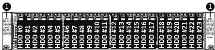
H262-Z6B

No. Decription
- Front Panel LEDs and buttons
NOTE! The Green HDD Latch Supports NVMe

- Please Go to Chapter 2-3 Front Panel LED and Buttons for detail description of function LEDs.
2-2 Rear View

No. Decription
- PCIe Card Slot #1
- PCIe Card Slot #2
- CMC LAN Port
- Mezzanine Card Slot (Option/OCP V3.0 Card)
- 10/100/1000 Server Management LAN Port
- GbE LAN Port x 2
- USB 3.0 Port x 2
- Mini DP Port
2-3 Front Panel LED and Buttons

| No. | Name | Color | Status | Description |
| 1. | System Status LED | This LED represents the RoT function LED behavior. Please see the following section for detail LED behavior. | ||
| 2. | Reset Button -- -- Press this button to reset the system. | |||
| 3. | Power button with LED | Green On System is powered on | ||
| Green Blink System is in ACPI S1 state (sleep mode) | ||||
| N/A Off | • System is not powered on or in ACPI S5 state (power off) • System is in ACPI S4 state (hibernate mode) | |||
| 4. | ID Button with LED | This LED represents the RoT function LED behavior. Please see the following section for detail LED behavior. | ||
| 5. | Enclosure | Green On System is operating normally. | ||
| Amber | On | Critical condition, may indicates: Power module failure System fan failure Power supply voltage issue System temperature | ||
| Blink | Non-critical condition, may indicates: Redundant power module failure Temperature and voltage issue | |||
| 6. | CMC Reset Button | -- -- Press this button to reset the CMC. | ||
2-4 RoT LEDs


| LED on Front panel (Note5) | ||
| ID LED Status LED | ||
| EC Firmware (FW) Authentication fail or not exit | ||
| EC FW is broken or not exit (Note1) | OFF OFF | |
| Authenticating/Recovering BMC/BIOS Images | ||
| Authenticating Images | OFF OFF | |
| Recovering BMC Active Flash | Blinks Blue 4 times per second | Blinks Green 4 times per second |
| Recovering BIOS Active Flash | Blinks Blue 4 times per second | Blinks Amber 4 times per second |
| Authentication (AUTH) Pass | ||
| Recovering BIOS Active Flash | OFF OFF | |
| BMC : AUTH pass after doing recovery BIOS : AUTH pass after doing recovery | OFF OFF | |
| BMC : AUTH pass after doing recovery BIOS : AUTH pass | OFF OFF | |
| BMC : AUTH pass BIOS : AUTH pass after doing recovery | OFF OFF | |
| Active Flash Authentication (AUTH) Fail | ||
| BMC : AUTH Fail (Note2) | Blinks Blue 1 time per second | Blinks Green 1 time per second |
| BIOS : AUTH fail (Note2) | Blinks Blue 1 time per second | Blinks Amber 1 time per second |
| BMC : AUTH fail after doing recovery (Note3) | Blinks Blue | Blinks Green |
| 2 times per second | 2 times per second | |
| [ON OFF OFF] | [ON OFF OFF] | |
| BIOS : AUTH fail after doing recovery (Note3) | Blinks Blue | Blinks Amber |
| 2 times per second | 2 times per second | |
| [ON OFF OFF] | [ON OFF OFF] | |
| Backup Flash Authentication Fail (Note4) | ||
| BMC : AUTH fail | Blinks Blue | Blinks Green |
| 2 times per second | 2 times per second | |
| [ON OFF ON OFF] | [ON OFF ON OFF] | |
| BIOS : AUTH fail | Blinks Blue | Blinks Amber |
| 2 times per second | 2 times per second | |
| [ON OFF ON OFF] | [ON OFF ON OFF] | |
NOTE!
- EC FW is broken or not exited result in Microchip CEC1702 cannot load EC FW for authentication.
2 (1) Authentication fail include below scenarios
Configuration table is missing or modified
Public key is missing or modified
Protected area or signature is modified
Flash empty
- if active flash is still authentication failed after recovery sequence, Microchip CEC1702 stop the process and showing LED behavior.
- If backup flash authentication is failed cause by configuration table, public key or protected area is broken. Microchip CEC1702 stop the process and showing LED behavior.
- Front panel LED is controlled by BMC or Microchip CEC1702. Once Microchip CEC1702 is working(Auth or recovery), the front panel LED is controlled by Microchip CEC1702 and vice versa.
2-5 Rear System LAN LEDs
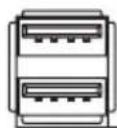


| No. | Name | Color | Status | Description |
| 1. | 1GbESpeed LED | Yellow On 1Gbps data rate | ||
| Green On 100 Mbps data rate | ||||
| N/A Off 10 Mbps data rate | ||||
| 2. | 1GbELink/Activity LED | Green | On Link between system and network or no access | |
| Blink Data transmission or receiving is occurring | ||||
| N/A Off No data transmission or receiving is occurring | ||||
2-6 Power Supply Unit LED

| State | Description |
| OFF No AC power to all power supplies | |
| 0.5Hz Green Blinking AC present / only standby on / Cold redundant mode | |
| 2Hz Green Blinking Power supply firmware updateing mode | |
| Amber | AC cord unplugged or AC power lost; with a second power supply in parallel still with AC input power |
| Power supply critical event causing shut down: failure, OCP, OVP, fan failure and UVP | |
| 0.5Hz Amber Blinking | Power supply warning events where the power supply continues to operate: high temp, high power, high current and slow fan |
2-7 Hard Disk Drive LEDs

| RAID SKU | LED1 | Locate | HDD Fault | Rebuilding | HDD Access | HDD Present (No Access) | |
| No RAID configuration (via HBA) | Disk LED (LED on Back Panel) | Green ON(*1) | OFF | BLINK (*2) | OFF | ||
| Amber OFF | OFF | OFF | OFF | ||||
| Removed HDD Slot (LED on Back Panel) | ON(*1)Green OFF | -- | -- | ||||
| OFFAmber OFF | -- | -- | |||||
| RAID configuration (via HW RAID Card or SW RAID Card) | Disk LED | Green | ON | OFF | BLINK (*2) | OFF | |
| Amber | OFF | ON | (Low Speed: 2 Hz) | OFF | OFF | ||
| Removed HDD Slot | Green | ON(*1) | OFF | (*3) | -- | -- | |
| Amber | OFF | ON | (*3) | -- | -- | ||
| LED 2 | HDD Present No | HDD |
| Green | ON | OFF |
NOTE:
*1: Depends on HBA/Utility Spec.
*2: Blink cycle depends on HDD's activity signal.
*3: If HDD is pulled out during rebuilding, the disk status of this HDD is regarded as faulty.
Chapter 3 System Hardware Installation

Pre-installation Instructions
Computer components and electronic circuit boards can be damaged electrostatic discharge. Working on computers that are still connected to a power supply can be extremely dangerous. Follow the simple guidelines below to avoid damage to your computer or injury to yourself.
- Always disconnect the computer from the power outlet whenever you are working inside the computer case.
- If possible, wear a grounded wrist strap when you are working inside the computer case. Alternatively, discharge any static electricity by touching the bare metal system of the computer case, or the bare metal body of any other grounded appliance.
- Hold electronic circuit boards by the edges only. Do not touch the components on the board unless it is necessary to do so. Do not flex or stress the circuit board.
- Leave all components inside the static-proof packaging until you are ready to use the component for the installation.
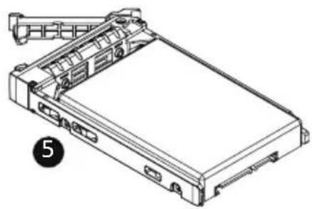
3-1 Installing the Hard Disk Drive

Read the following guidelines before you begin to install the Hard disk drive:
• Take note of the drive tray orientation before sliding it out.
- The tray will not fit back into the bay if inserted incorrectly.
- Make sure that the HDD is connected to the HDD connector on the backplane.
Follow these instructions to install the Hard disk drive:
- Press the release button.
- Extend the locking lever.
- Pull the locking lever to remove the HDD tray.
- Align the hard disk drive with the positioning stud on the HDD tray.
- Slide hard disk drive into the blank HDD tray.
- Reinsert the HDD tray into the slot and close the locking lever.


natural_image
Technical line drawing of a rectangular electronic device with mounting bracket and internal components (no text or symbols)3-2 Removing the Node
Follow these instructions to remove a node:
- Press the release latch while simultaneously pushing down the tray handle for the node.
- Pull the node out of the system.
- To install the node, push the node back into the system.

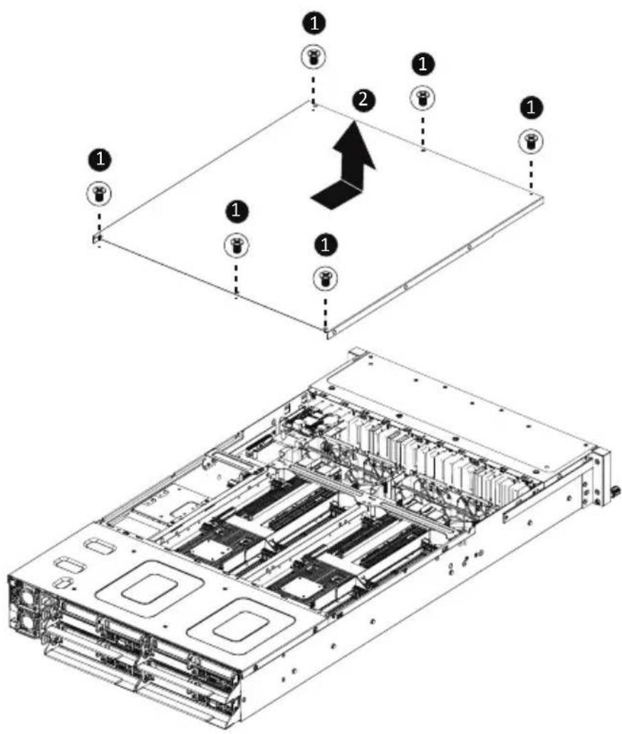
3-3 Removing Chassis Cover

Before you remove or install the system cover
- Make sure the system is not turned on or connected to AC power.
Follow these instructions to remove the system cover:
- Loosen and remove the six screws securing the back cover.
- Slide the cover to the rear of the system and remove the cover in the direction of the arrow.
3-4 Removing and Installing the Fan Duct
Follow these instructions to remove/install the fan duct:
- Remove the two screws securing the fan ducts.
- Lift up to remove the fan ducts
- To install the fan duct, align the fan duct with the guiding groove. Push down the fan duct into chassis until its firmly seats, then install the four screws to secure the fan ducts in place.
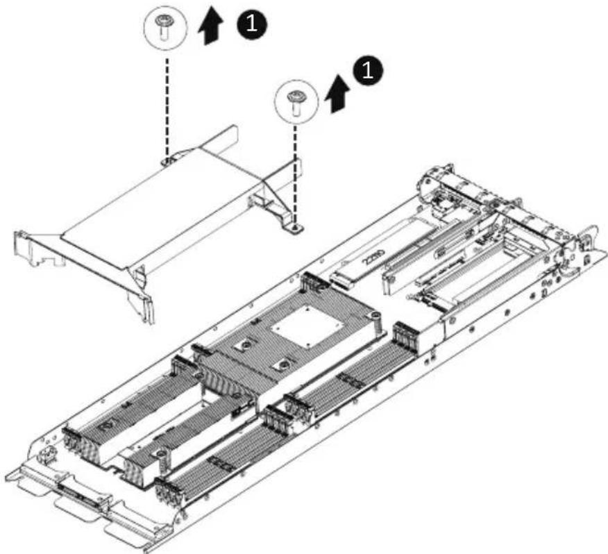
3-5 Removing and Installing the Heatsink
Read the following guidelines before you begin to install the heatsink:
- Always turn off the computer and unplug the power cord from the power outlet before installing the heatsink to prevent hardware damage.
- Unplug all cables from the power outlets.
- Disconnect all telecommunication cables from their ports.
- Place the system unit on a flat and stable surface.
- Open the system according to the instructions.
WARNING!
Failure to properly turn off the server before you start installing components may cause serious damage. Do not attempt the procedures described in the following sections unless you are a qualified service technician.
Follow these instructions to remove the heatsink:
- Loosen the four captive screws securing the heatsink to the system.
- Lift and remove the heatsink.

WARNING!
CPU0 and CPU1 use different CPU heatsinks. See the following images for using the correct heatsink.
Failure to observe the warning could result in damage to the equipment.

- When installing the heatsink to CPU, use PHILLIPS #2-Lobe driver to tighten 4 captive nuts in sequence as 1-4.
• The screw tightening torque: 0 ± 0.5 kgf-cm ( 22.0 ± 1.0 lbf-in).
CPU0 Heatsink

CPU1 Heatsink:
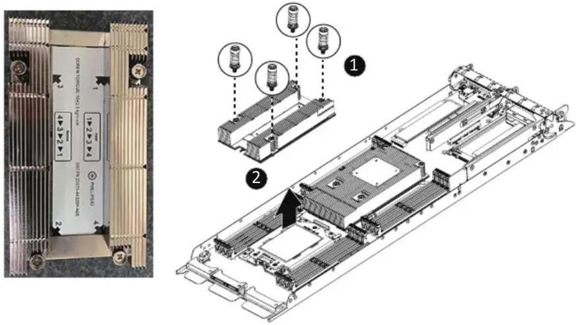
To install the heatsink, reverse the steps above while ensuring that you tighten the captive screws in sequential order (1→2→3→4) as seen in the image below.
CPU0 Heatsink CPU1 Heatsink:

3-6 Installing the CPU

Read the following guidelines before you begin to install the CPU:
• Make sure that the motherboard supports the CPU.
• Always turn off the computer and unplug the power cord from the power outlet before installing the CPU to prevent hardware damage.
- Unplug all cables from the power outlets.
- Disconnect all telecommunication cables from their ports.
- Place the system unit on a flat and stable surface.
- Open the system according to the instructions.
WARNING!
Failure to properly turn off the server before you start installing components may cause serious damage. Do not attempt the procedures described in the following sections unless you are a qualified service technician.
Follow these instructions to install the CPU:
- Loosen the three captive screws in sequential order (1 →2→3) securing the CPU cover.
- Flip open the CPU cover.
- Remove the CPU cap with CPU from the CPU frame using the handle on the CPU cap.
- Using the handle on the CPU cap insert the new CPU cap with CPU installed into the CPU frame.
NOTE: Ensure the CPU is installed in the CPU cap in the correct orientation, with the gold triangle on the CPU aligned to the top left corner of the CPU cap. - Flip the CPU frame with CPU installed into place in the CPU socket.
- Flip the CPU cover into place over the CPU socket.
- Tighten the CPU cover screws in sequential order (1 →2→3) to secure the CPU cover in place.

flowchart
graph TD
    A["1: External cap"] --> B["2: Internal component"]
    B --> C["3: External component"]
    C --> D["4: External component"]
    D --> E["5: Internal component"]
    E --> F["6: Internal component"]
    F --> G["7: Internal component"]
    G --> H["8: Internal component"]

- When installing the heat sink over the CPU, use T30-Lobe driver to tighten the 4 captive nuts in sequential order (1→2→3→4).
• The screw tightening torque: 8 ± 0.5kgf-cm (17.0± 1.0 lbf-in)
3-7 Installing Memory

Read the following guidelines before you begin to install the memory:
- Make sure that the motherboard supports the memory. It is recommended that memory of the same capacity, brand, speed, and chips be used.
- Always turn off the computer and unplug the power cord from the power outlet before installing the memory to prevent hardware damage.
- Memory modules have a foolproof design. A memory module can be installed in only one direction. If you are unable to insert the memory, switch the direction.
3-7-1 Eight Channel Memory Configuration
This motherboard provides 16 DDR4 memory sockets and supports Eight Channel Technology. After the memory is installed, the BIOS will automatically detect the specifications and capacity of the memory. Enabling eight Channel memory mode will be eight times of the original memory bandwidth.

3-7-2 Installing the Memory

Before installing a memory module, make sure to turn off the computer and unplug the power cord from the power outlet to prevent damage to the memory module.
Be sure to install DDR4 DIMMs on this motherboard.
Follow these instructions to install the Memory:
- Insert the DIMM memory module vertically into the DIMM slot, and push it down.
- Close the plastic clip at both edges of the DIMM slots to lock the DIMM module.
- Reverse the installation steps when you want to remove the DIMM module.
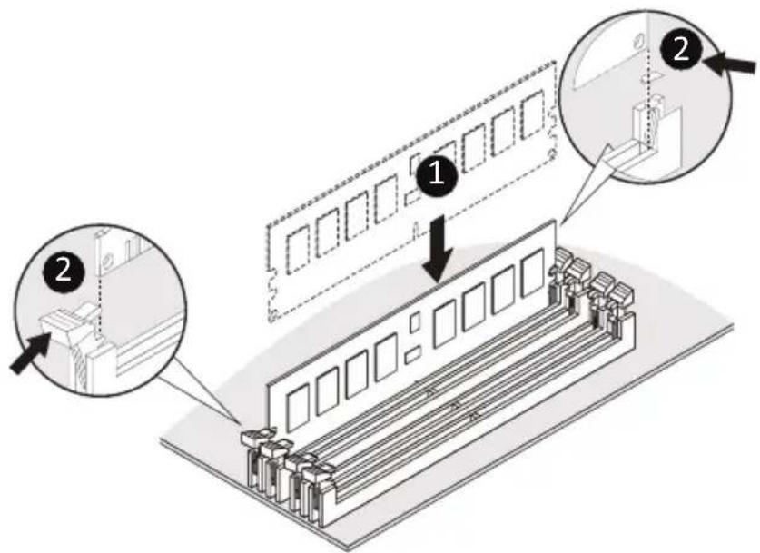
3-7-3 Processor and Memory Module Matrix Table
| Processor and Memory Module Matrix Table | ||||||||||||||||
| CPU# | Channel A/I | Channel B/J | Channel C/K | Channel D/L | Channel E/M | Channel F/N | Channel G/O | Channel H/P | ||||||||
| 8 DIMMs | ||||||||||||||||
| CPU0 | A1 B1 | C1 D1 | E1 F1 | G1 H1 | ||||||||||||
| 16 DIMMs | ||||||||||||||||
| CPU0 | A0 | A1 | B0 | B1 | C0 | C1 | D0 | D1 | E0 | E1 | F0 | F1 | G0 | G1 | H0 | H1 |
| 16 DIMMs | ||||||||||||||||
| CPU0 | A1 B1 | C1 D1 | E1 F1 | G1 H1 | ||||||||||||
| CPU1 | I1 | J1 | K1 | L1 | M1 | N1 | O1 | P1 | ||||||||
| 32 DIMMs | ||||||||||||||||
| CPU0 | A0 | A1 | B0 | B1 | C0 | C1 | D0 | D1 | E0 | E1 | F0 | F1 | G0 | G1 | H0 | H1 |
| CPU1 | I0 | I1 | J0 | J1 | K0 | K1 | L0 | L1 | M0 | M1 | N0 | N1 | O0 | O1 | P0 | P1 |
3-7-4 Memory Population Table

- When only one DIMM is used, it must be populated in memory slot DIMM1.
EPYC Memory Speed based on DIMM Population (One DIMM per Channel)
| DIMM Type | DIMM Population | Max EPYC 7003 DDR Frequency (MHz) |
| DIMM 0 | ||
| RDIMM | 1R (1 Rank) 3200 | |
| 2R or 2DR (2 Ranks) 3200 | ||
| LRDIMM | 4DR (4 Ranks) 3200 | |
| 2S2R (4 Ranks) 3200 | ||
| 2S4R (8 Ranks) 3200 |
EPYC Memory Speed based on DIMM Population (Two DIMM per Channel)
| DIMM Type | DIMM Population | Max EPYC 7003 DDR Frequency (MHz) | |
| DIMM 0 DIMM 1 | |||
| RDIMM | --1R 3200 | ||
| 1R1R | 2933 | ||
| -- | 2R or 2DR | 3200 | |
| 1R | 2R or 2DR | 2933 | |
| 2R or 2DR | 2R or 2DR 2933 | ||
| LRDIMM | -- | 4DR3200 | |
| 4DR | 4DR2933 | ||
| -- | 2S2R (4 Ranks) | 3200 | |
| -- | 2S4R (8 Ranks) | 3200 | |
| 2S2R (4 Ranks) | 2S2R (4 Ranks) | 2933 | |
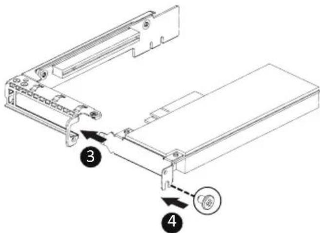
3-8 Installing the PCI Expansion Card

- The PCI riser assembly does not include a riser card or any cabling as standard. To install a PCI card, a riser card must be installed.
Follow these instructions to install the right PCI Expansion card:
- Remove the two screws securing the riser bracket to the system.
- Lift up the riser bracket out of system.
- Align the PCI-E card to the riser guide slot and push in the direction of the arrow until the PCI-E card sits in the PCI card connector.
- Secure the PCI-E card with a screw.
- Reverse steps 1 - 3 to install the riser bracket back into the system.


Follow these instructions to install the left PCI Expansion card:
- Remove the three screws on the riser bracket to the system.
- Lift up the riser bracket out of system.
- Remove the screw securing the side bracket to the riser bracket.
- Remove the side bracket
- Align the PCI-E card to the riser guide slot and push in the direction of the arrow until the PCI-E card sits in the PCI card connector.
- Secure the PCI-E card with a screw.
- Install the side bracket to the riser bracket.
- Secure the side bracket to the riser bracket with a screw.
- Reverse steps 1 - 2 to install the riser bracket back into the system.
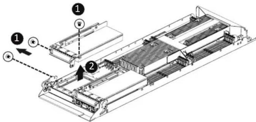
3-9 Installing the Mezzanine Card
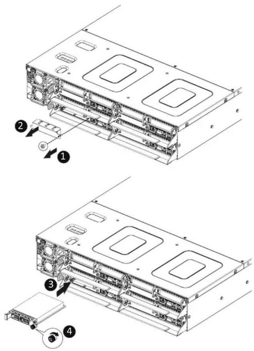
3-9-1 Installing the OCP 3.0 Mezzanine Card

Use of the following type of OCP 3.0 NIC is recommended:
- OCP 3.0 SFF with pull tab
• OCP 3.0 SFF with ejector latch
Follow these instructions to install an OCP 3.0 Mezzanine card:
- Remove the one screw securing the OCP 3.0 card slot cover.
- Remove the slot cover from the system.
- Insert the OCP 3.0 card into the card slot ensuring that the card is firmly connected to the connector on the motherboard.
- Tighten the thumbnail screw to secure the OCP 3.0 card in place.
- Reverse steps 3-4 to replace the OCP 3.0 card.
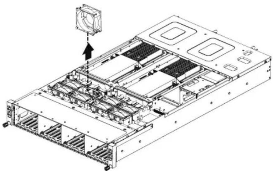
3-10 Replacing the Fan Assembly

- Voltages can be present within the server whenever an AC power source is connected. This voltage is present even when the main power switch is in the off position. Ensure that the system is powered-down and all power sources have been disconnected from the server prior to replacing a system fan.
Failure to observe these warnings could result in personal injury or damage to equipment.
Follow these instructions to replace the fan assembly:
- Lift up the fan assembly from the chassis.
- Reverse the previous steps to install the replacement fan assembly.
natural_image
Technical line drawing of a server rack with internal components and a fan component (no text or symbols)3-11 Replacing the Power Supply
Follow these instructions to replace the power supply:
- Pull up the power supply handle and press the retaining clip on the right side of the power supply along the direction of the arrow. At the same time, pull out the power supply by using its handle.
- Insert the replacement power supply firmly into the chassis. Connect the AC power cord to the replacement power supply.

3-12 Replacing Power Distribution Board Cage

Before you remove or install the power distribution board cage: • Make sure the system is not turned on or connected to AC power.
Follow these instructions to remove the power distribution board cage:
- Loosen and remove the four screws securing the cage.
- While holding the cage, slide the cage to the front of the system and remove the cage in the direction of the arrow.

3-13 Cable Routing
3-13-1 H262-Z6A
Front Switch Cable/Front LED Cable

natural_image
Technical line drawing of a server rack with multiple drive bays and internal compartments (no text or labels)PMBus Cable

natural_image
Technical line drawing of an internal server rack with multiple drive bays and ventilation slots (no text or labels)Power Distribution Board to Middle Board Cable (Top)
natural_image
Technical schematic of a server rack with multiple drive bays and internal compartments (no text or labels visible)Power Distribution Board to Middle Board Cable (Bottom)

natural_image
Technical schematic of a server rack with multiple drive bays and internal compartments (no text or labels visible)Top Middle Board to HDD Back Plane Board Cable (SATA1)

natural_image
Technical schematic of a server rack with multiple drive bays and internal components (no text or labels visible)Bottom Middle Board to HDD Back Plane Board Cable (SATA2)
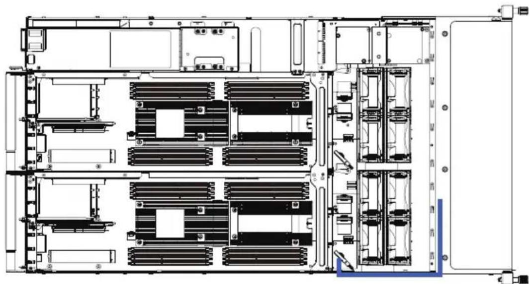
natural_image
Technical schematic of a server rack with multiple drive bays and internal compartments (no text or labels visible)Top Middle Board to HDD Back Plane Board Cable (SATA3)

natural_image
Technical line drawing of a server rack with multiple drive bays and internal compartments (no text or labels)Bottom Middle Board to HDD Back Plane Board Cable (SATA4)

natural_image
Technical schematic of a server rack with multiple drive bays and internal components (no text or labels visible)Top Middle Board to HDD Back Plane Board Cable (NVMe/Node1)
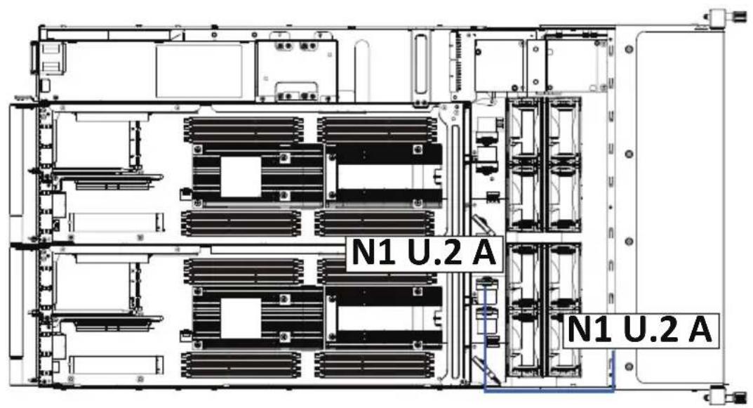
Top Middle Board to HDD Back Plane Board Cable (NVMe/Node1)

Top Middle Board to HDD Back Plane Board Cable (NVMe/Node3)
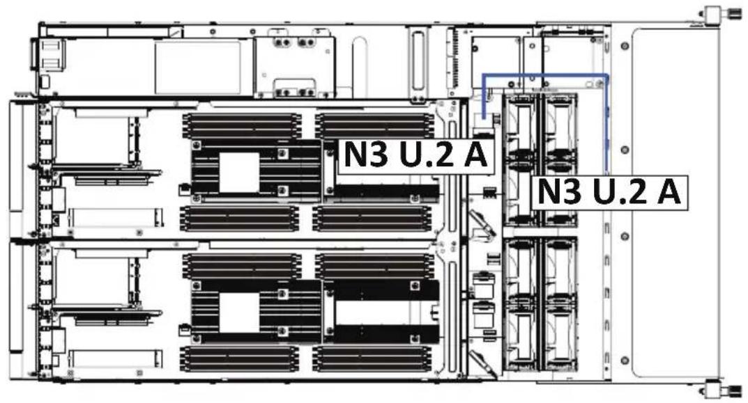
Top Middle Board to HDD Back Plane Board Cable (NVMe/Node3)


Bottom Middle Board to HDD Back Plane Board Cable (NVMe/Node2)
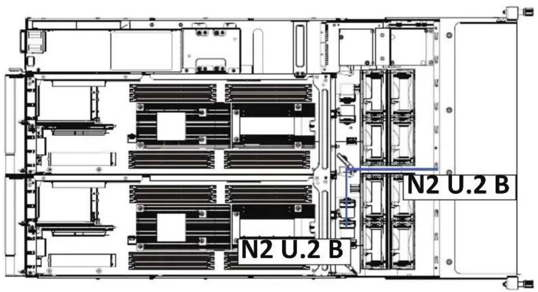
Bottom Middle Board to HDD Back Plane Board Cable (NVMe/Node4)
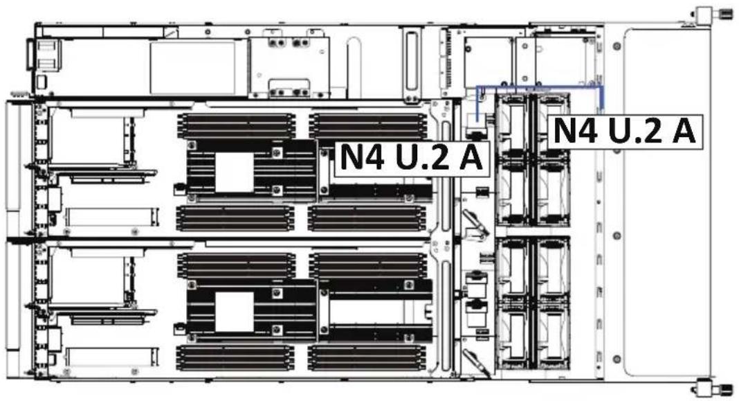
Bottom Middle Board to HDD Back Plane Board Cable (NVMe/Node4)

LAN Bridge Cable

natural_image
Technical schematic of a server rack with multiple drive bays and internal compartments (no text or labels visible)On-Board SATA to HDD Back Plane Board Cable

natural_image
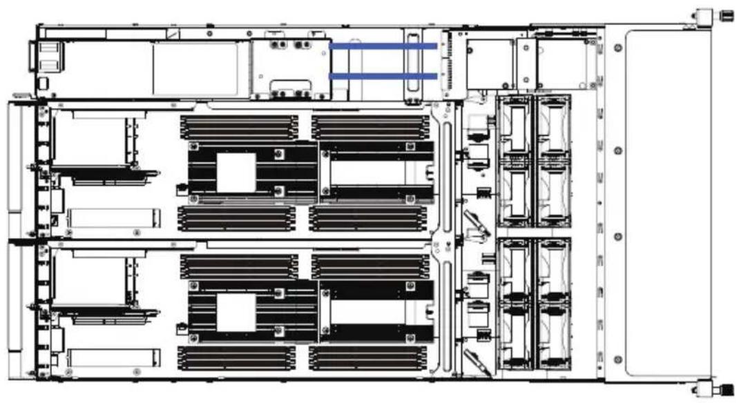
Technical schematic of a server rack with multiple drive bays and internal compartments (no text or labels visible)3-13-2 H262-Z6B
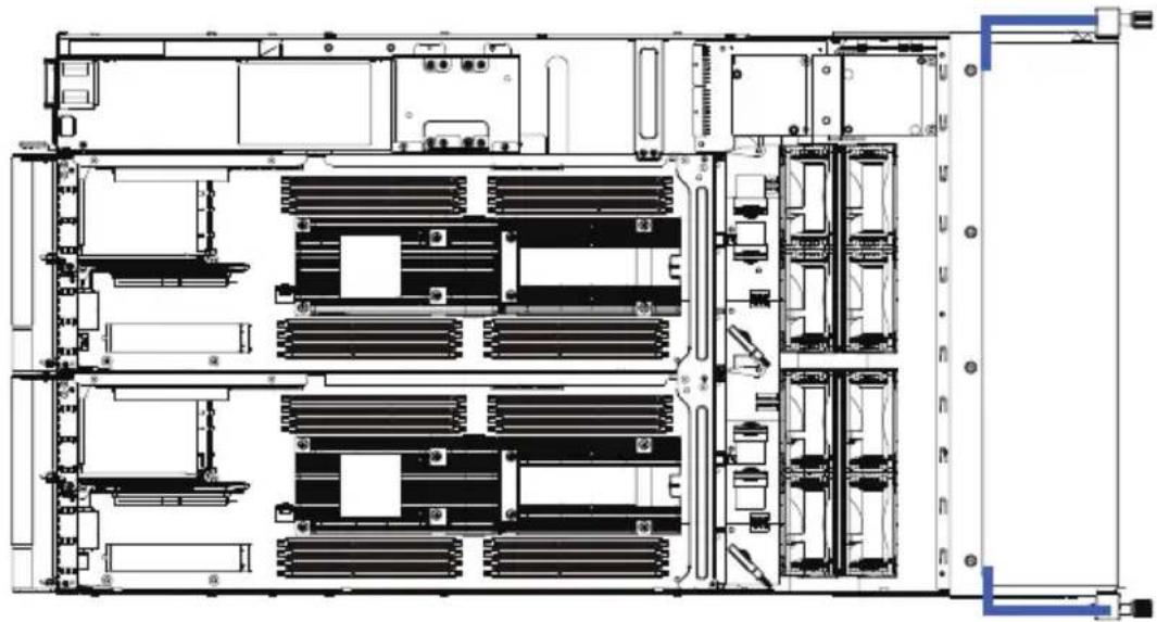
Front Switch Cable/Front LED Cable
natural_image
Architectural floor plan of a server room showing internal components and ventilation ducts (no text or labels)PMBus Cable

natural_image
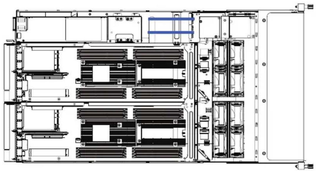
Technical schematic of a server rack with multiple drive bays and internal components (no text or labels visible)Power Distribution Board to Middle Board Cable (Top)
natural_image
Technical line drawing of a server rack with multiple drive bays and internal compartments (no text or labels)Power Distribution Board to Middle Board Cable (Bottom)

natural_image
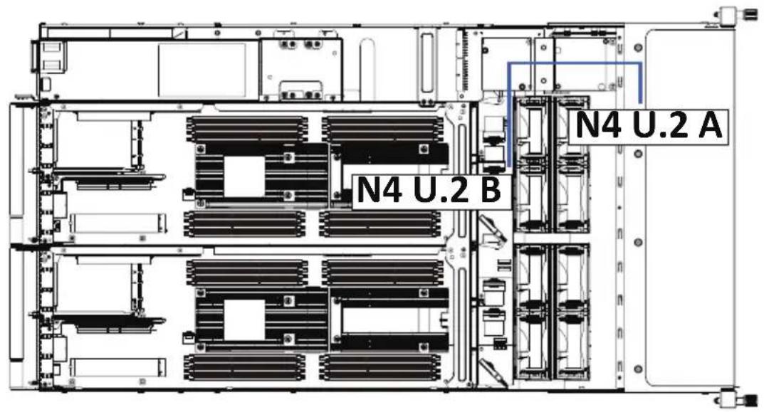
Technical schematic of a server rack with multiple drive units and internal compartments (no text or labels visible)Top Middle Board to HDD Back Plane Board Cable (NVMe/Node1)

Bottom Middle Board to HDD Back Plane Board Cable (NVMe/Node2)

Top Middle Board to HDD Back Plane Board Cable (NVMe/Node3)
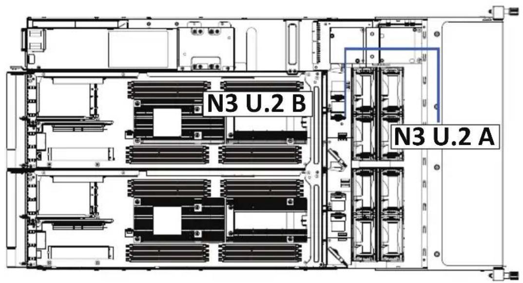
Bottom Middle Board to HDD Back Plane Board Cable (NVMe/Node4)

natural_image
Technical schematic of a server rack with multiple drive bays and internal compartments (no text or labels visible)On-Board SATA to HDD Back Plane Board Cable

natural_image
Technical schematic of a server rack with multiple drive bays and internal compartments (no text or labels visible)This page intentionally left blank
Chapter 4 Motherboard Components
4-1 Motherboard Components

Item Description
1 OCP Mezzanine 3.0 Connector
2 Proprietary PCIe Slot #2 (Gen 4/x16 slot/GENZ_2)
3 NCSI Switch
4 Server Management LAN Port
5 GbE LAN Port #2
6 GbE LAN Port #1
7 USB 3.0 Port x 2
8 Mini DP Port
9 Serial Port Cable Connector
10 M.2 Connector (PCIe x4, Supports NGFF-22110)
11 IPMB Connector
12 Proprietary PCIe Slot #L (Gen 4/x8 slot/GENZ_L)
13 SlimLine SAS Connector (SL4_SATA0/PCIe/SATA)
14 Power & PCIe/SATA Connector
15 Power & PCIe/SATA Connector
16 Power & PCIe/SATA Connector
17 SGPIO Connector #B
18 SGPIO Connector #A
19 Proprietary PCIe Slot #R (Gen 4/x16 slot/GENZ_R)
20 Proprietary PCIe Slot #1 (Gen 4/x16 slot/GENZ_1)
21 System Battery Socket
22 TPM Connector
23 Function Jumper Switch
24 SlimLine SAS Connector (SATA0)
4-2 Jumper Setting
![J1 ON DIP 1 2 3 4 J1 ON OFF HOST_SMBUS_SEL BIOS Defined 1 2 NA NA 3 BIOS_PWD Clear supervisor password Normal [Default] 4 BIOS_RCVR BIOS recovery mode Normal [Default] NCSI Switch ON OFF Onboard LAN ON OCP 3.0 Mezzanine Clear CMOS CLR_CMOS EnableDefault](/content/2026/05/1109911/images/9840b3a9bf49ed4566f6a6f1df9cca02b9e13cfd3254b4df5f9dd0f9bc8df453.jpg)
Chapter 5 BIOS Setup
BIOS (Basic Input and Output System) records hardware parameters of the system in the EFI on the motherboard. Its major functions include conducting the Power-On Self-Test (POST) during system startup, saving system parameters, loading the operating system etc. The BIOS includes a BIOS Setup program that allows the user to modify basic system configuration settings or to activate certain system features. When the power is turned off, the battery on the motherboard supplies the necessary power to the CMOS to keep the configuration values in the CMOS.
To access the BIOS Setup program, press the key during the POST when the power is turned on.

- BIOS flashing is potentially risky, if you do not encounter any problems when using the current BIOS version, it is recommended that you don't flash the BIOS. To flash the BIOS, do it with caution. Inadequate BIOS flashing may result in system malfunction.
- It is recommended that you not alter the default settings (unless you need to) to prevent system instability or other unexpected results. Inadequately altering the settings may result in system's failure to boot. If this occurs, try to clear the CMOS values and reset the board to default values. (Refer to the Exit section in this chapter or introductions of the battery/clearing CMOS jumper in Chapter 4 for how to clear the CMOS values.)
BIOS Setup Program Function Keys
| <←><→> | Move the selection bar to select the screen |
| <↑><↓> | Move the selection bar to select an item |
| <+> | Increase the numeric value or make changes |
| <-> | Decrease the numeric value or make changes |
| Execute command or enter the submenu | |
| Main Menu: Exit the BIOS Setup programSubmenus: Exit current submenu | |
| Show descriptions of general help | |
| Restore the previous BIOS settings for the current submenus | |
| Load the Optimized BIOS default settings for the current submenus | |
| Save all the changes and exit the BIOS Setup program |
Main
This setup page includes all the items of the standard compatible BIOS.
■ Advanced
This setup page includes all the items of AMI BIOS special enhanced features.
(ex: Auto detect fan and temperature status, automatically configure hard disk parameters.)
AMD CBS
This setup page includes the common items for configuration of AMD motherboard-related information.
AMD PBS Option
This setup page includes the common items for configuration of AMD CPM RAS related settings.
Chipset
This setup page includes all the submenu options for configuring the functions of the North Bridge.
■ Server Management
Server additional features enabled/disabled setup menus.
■ Security
Change, set, or disable supervisor and user password. Configuration supervisor password allows you to restrict access to the system and BIOS Setup.
A supervisor password allows you to make changes in BIOS Setup.
A user password only allows you to view the BIOS settings but not to make changes.
Boot
This setup page provides items for configuration of the boot sequence.
■ Save & Exit
Save all the changes made in the BIOS Setup program to the CMOS and exit BIOS Setup. (Pressing
Abandon all changes and the previous settings remain in effect. Pressing
5-1 The Main Menu
Once you enter the BIOS Setup program, the Main Menu (as shown below) appears on the screen. Use arrow keys to move among the items and press
Main Menu Help
The on-screen description of a highlighted setup option is displayed on the bottom line of the Main Menu.
Submenu Help
While in a submenu, press

- When the system is not stable as usual, select the Restore Defaults item to set your system to its defaults.
- The BIOS Setup menus described in this chapter are for reference only and may differ by BIOS version.

![Aptio Setup - AMI Main Advanced AND OBS AND PBS Option Offset Server Mont Security Boot Save & Exit Processor Information CPU 0 Brand String CPU 1 Brand String CPU Speed Processor Core Microcode Patch Total Memory Memory Speed VR Information Version ROESA PI Version PI Version Onboard LAN Information LAN1 MAC Address LAN2 MAC Address System Date System Time AND EPYC 7313 16-Core Processor AND EPYC 7313 16-Core Processor 3000 MHz 16 A001119 32768 MB 2667 MT/s 8434 1.0.0.1 84-2E-99-78-50-A0 84-2E-99-78-50-A1 (Fri 01/08/2021) [21:26:08] Set the Time, Use Tab to switch between Time elements. ++: Select Screen N: Select Item Enter: Select +/- Change Opt. F1: General Help F3: Previous Values F9: Optimized Defaults F10: Save & Exit ESC: Exit](/content/2026/05/1109911/images/b5470e9aba7df559a4970ef0b7a6a5d6118b4ef3221603db262d6fa9a9a8fe08.jpg)
| Parameter | Description |
| BIOS Information | |
| Project Name | Displays the project name information. |
| Project Version | Displays version number of the BIOS setup utility. |
| Build Date and Time | Displays the date and time when the BIOS setup utility was created. |
| BMC Information | |
| BMC Firmware Version | Displays BMC firmware version information. |
| CPU Brand String / CPU Speed / Processor Core / Microcode Patch | Displays the technical information for the installed processor(s). |
| Total Memory (Note3) | Displays the total memory size of the installed memory. |
| Memory Frequency (Note3) | Displays the frequency information of the installed memory. |
| VR Information Version Displays VR version information. | |
| AGESA PI Version PI Version Displays AGESA PI version information. | |
| Onboard LAN Information | |
| LAN1 MAC Address (Note1) | Displays LAN MAC address information. |
| LAN2 MAC Address (Note2) | Displays LAN MAC address information. |
| System Date | Sets the date following the weekday-month-day-year format. |
| System Time | Sets the system time following the hour-minute-second format. |
(Note1) The number of LAN ports listed will depend on the motherboard / system model.
(Note2) This section will display capacity and frequency information of the memory that the customer has installed.
5-2 Advanced Menu
The Advanced Menu displays submenu options for configuring the function of various hardware components. Select a submenu item, then press
When Boot Mode Select is set to UEFI (Default)

When "Boot Mode Select" is set to Legacy in the Boot > Boot Mode Select section

5-2-1 Trusted Computing
![Optio Setup - AKI Advanced Configuration Security Device Support [Enable] SPI TPM Support [Enabled] NO Security Device Found Enables or Disables BIOS support for security device. O.S. will not show Security Device. TCG EFI protocol and INTIA Interface will not be available. +: Select Screen +/-: Select Item Enter: Select +/-: Change Opt. F1: General Help F3: Previous Values F9: Optimized Defaults F10: Save & Exit ESC: Exit](/content/2026/05/1109911/images/7096e66d57c763068dd37c36e7e7dfa2620b2d8ff3985fce4e8a1a8ad7f3e35a.jpg)
| Parameter | Description |
| Configuration | |
| Security Device Support | Enable/Disable BIOS support for security device. OS will not show security device. TCG EFI protocol and INT1A interface will not be available.Options available: Enable/Disable. Default setting is Enable. |
| SPI TPM Support | Select Enable to activate TPM support feature.Options available: Enabled/Disabled. Default setting is Disabled |
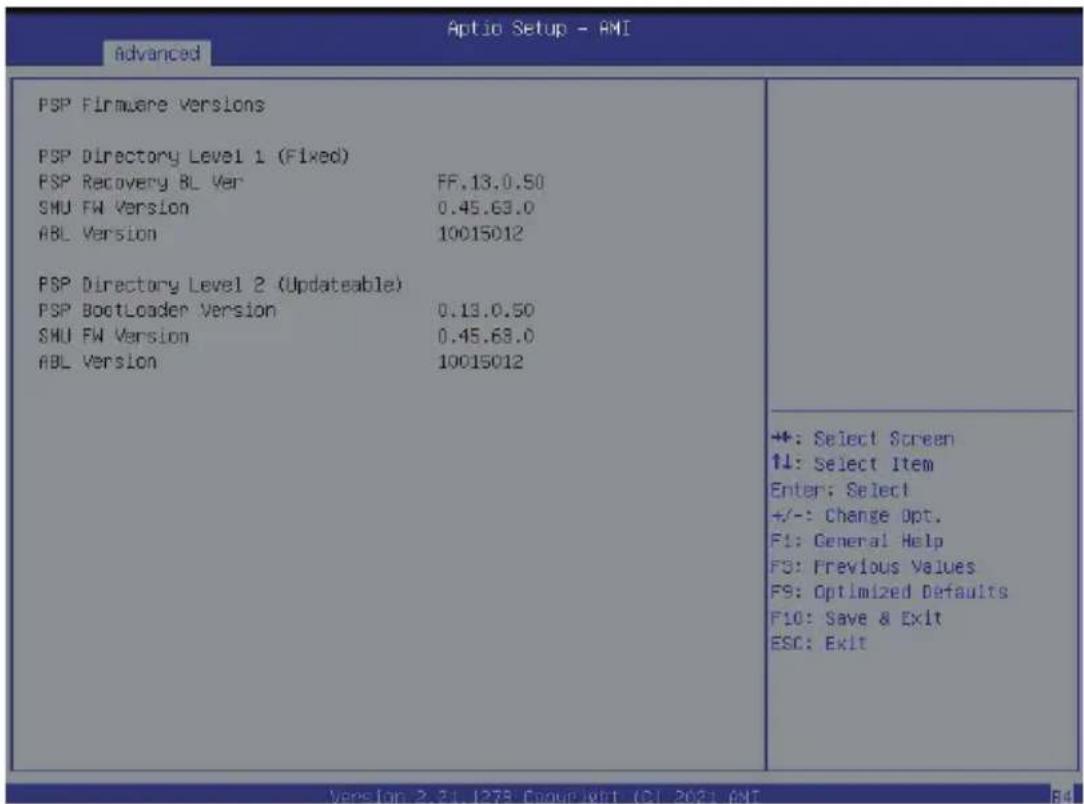
5-2-2 PSP Firmware Versions
The PSP Firmware Versions page displays the basic PSP firmware version information. Items on this window are non-configurable.
5-2-3 Legacy Video Select
![Optio Setup - AMI Advanced OnBrd/Ext VGA Select [Onboard] Select between onboard or external VGA support. +: Select Screen T4: Select Item Enter: Select +/-: Change Opt. F1: General Help F3: Previous Values F9: Optimized Defaults F10: Save & Exit ESC: Exit Version 2.21.1279 Copyright (C) 2021 AMI](/content/2026/05/1109911/images/d9f12f4f466421e4a6cd415160eaf6d9d1b43474a76b9c0f7c184ac3b6d12ae9.jpg)
| Parameter | Description |
| OnBrd/Ext VGA Select (Note) | Selects between onboard or external VGA support.Options available: Auto, Onboard, External. Default setting is Onboard. |
(Note) This configurable option will be displayed when "Boot Mode Select" is set to Legacy in the Boot > Boot Mode Select section.
5-2-4 AST2500 Super IO Configuration

| Parameter | Description |
| AST2500 Super IO Configuration | |
| Super IO Chip Displays the super IO chip information | |
| Serial Port 1 Configuration | Press [Enter] for configuration of advanced items. |
5-2-4-1 Serial Port 1 Configuration
![Aptio Setup Utility - Copyright (C) 2020 American Megatrends, Inc. Advanced Serial Port 1 Configuration Serial Port [Enabled] Device Settings IO=3F6h; IRQ=4; Change Settings [Auto] Enable or Disable Serial Port (COM) +: Select Screen 11: Select Item Enter: Select +/-: Change Opt. F1: General Help F3: Previous Values F9: Optimized Defaults F10: Save & Exit ESC: Exit version 8.20.1275. Copyright (C) 2020 American Megatrends, Inc. B4](/content/2026/05/1109911/images/33dc7cef21cace2c97b9aa89e3cb0e2296e858f403b8b48b9d90b7f8fe978bcd.jpg)
| Parameter | Description |
| Serial Port 1 Configuration | |
| Serial Port(Note1) | Enable/Disable the Serial Port (COM). When set to Enabled allows you to configure the Serial port 1/2 settings. When set to Disabled, displays no configuration for the serial port.Options available: Enabled/Disabled. Default setting is Enabled. |
| Devices Settings(Note2) | Displays the Serial Port 1/2 device settings. |
| Change Settings(Note2) | Select an optimal settings for Super IO Device.Options available for Serial Port 1:AutoIO=3F8h; IRQ=4;IO=3F8h; IRQ=3, 4, 5, 6, 7, 9, 10, 11, 12;IO=2F8h; IRQ=3, 4, 5, 6, 7, 9, 10, 11, 12;IO=3E8h; IRQ=3, 4, 5, 6, 7, 9, 10, 11, 12;IO=2E8h; IRQ=3, 4, 5, 6, 7, 9, 10, 11, 12;Default setting is Auto.Options available for Serial Port 2:AutoIO=2F8h; IRQ=3;IO=3F8h; IRQ=3, 4, 5, 6, 7, 9, 10, 11, 12;IO=2F8h; IRQ=3, 4, 5, 6, 7, 9, 10, 11, 12;IO=3E8h; IRQ=3, 4, 5, 6, 7. 9, 10, 11, 12;IO=2E8h; IRQ=3, 4, 5, 6, 7, 9, 10, 11, 12;Default setting is Auto.Please note that this item is configurable when Serial Port is set to Enabled. |
(Note1) Advanced items prompt when this item is defined.
(Note2) This item appears when Serial Port is set to Enabled.
5-2-5 S5 RTC Wake Settings
| Optio Setup - AMI | |
| Advanced | |
| Wake system from 85 [Disabled] | Enable or disable System wake on alarm event. Select FixedTime, system will wake on the hr::min::sec specified. Select DynamicTime, System will wake on the current time + Increase minute(s) |
| +: Select Screen T1: Select Item Enter: Select +/-: Change Opt. F1: General Help F3: Previous Values F9: Optimized Defaults F10: Save & Exit ESC: Exit | |
| Version: 2.21.1275 Copyright (C) 2021 AMI | |
| Parameter | Description |
| Wake System from S5(Note1) | Enable/Disable system wake on alarm event. |
| Options available: Disabled/Fixed Time. When Fixed Time enabled, system will wake on the hr::min::sec specified. | |
| Default setting is Disabled. |
(Note1) Advanced items prompt when this item is defined.
5-2-6 Serial Port Console Redirection
![Optio Setup - AMI Advanced COM1/SOL Console Redirection [Disabled] ► Console Redirection Settings Legacy Console Redirection ► Legacy Console Redirection Settings Serial Port for Out-of-Band Management/ Windows Emergency Management Services (EMS) Console Redirection EMS [Disabled] ► Console Redirection Settings Console Redirection Enable or Disable. +: Select Screen ↑↓: Select Item Enter: Select +/-: Change Opt. F1: General Help F3: Previous Values F9: Optimized Defaults F10: Save & Exit ESC: Exit ++: Select Screen ↑↓: Select Item Enter: Select +/-: Change Opt. F1: General Help F3: Previous Values F9: Optimized Defaults F10: Save & Exit ESC: Exit](/content/2026/05/1109911/images/05e7837493d7b725ed307ed4a75e84f552f82e9c234e380a704b2d6b2dfb62d5.jpg)
| Parameter | Description |
| COM1 Serial Over LAN (Note) | Select whether to enable console redirection for specified device. Console redirection enables the users to manage the system from a remote location.Options available: Enabled/Disabled. Default setting is Disabled. |
| COM1 Serial Over LANConsole Redirection Settings | Press [Enter] to configure advanced items.Please note that this item is configurable when COM1/Serial Over LAN & COM2 Console Redirection is set to Enabled.Terminal Type- Selects a terminal type to be used for console redirection.- Options available: VT100, VT100+, ANSI, VT-UTF8. Default setting is ANSI.Bits per second- Selects the transfer rate for console redirection.- Options available: 9600, 19200, 38400, 57600, 115200. Default setting is 115200.Data Bits- Selects the number of data bits used for console redirection.- Options available: 7/8. Default setting is 8. |
(Note) Advanced items prompt when this item is defined.
| Parameter | Description |
| COM1/Serial Over LAN Console Redirection Settings (continued) | Parity– A parity bit can be sent with the data bits to detect some transmission errors.– Even: parity bit is 0 if the num of 1's in the data bits is even.– Odd: parity bit is 0 if num of 1's in the data bits is odd.– Mark: parity bit is always 1. Space: Parity bit is always 0.– Mark and Space Parity do not allow for error detection.– Options available: None, Even, Odd, Mark, Space. Default setting is None.Stop Bits– Stop bits indicate the end of a serial data packet. (A start bit indicates the beginning). The standard setting is 1 stop bit.Communication with slow devices may require more than 1 stop bit.– Options available: 1/2. Default setting is 1.Flow Control– Flow control can prevent data loss from buffer overflow. When sending data, if the receiving buffers are full, a 'stop' signal can be sent to stop the data flow. Once the buffers are empty, a 'start' signal can be sent to re-start the flow. Hardware flow control uses two wires to send start/stop signals.– Options available: None, Hardware RTS/CTS. Default setting is None.VT-UTF8 Combo Key Support– Enable/Disable the VT-UTF8 Combo Key Support.– Options available: Enabled/Disabled. Default setting is Enabled.Recorder Mode (Note) – When this mode enabled, only texts will be send. This is to capture Terminal data.– Options available: Enabled/Disabled. Default setting is Disabled.Resolution 100x31 (Note) – Enable/Disable extended terminal resolution.– Options available: Enabled/Disabled. Default setting is Enabled.Putty KeyPad (Note) – Selects FunctionKey and LeyPad on Putty.– Options available: VT100, LINUX, XTERMR6, SC0, ESCN, VT400. Default setting is VT100. |
(Note) Advanced items prompt when this item is defined.
| Parameter | Description |
| Legacy Console Redirection | |
| Legacy Console Redirection Settings | Press [Enter] to configure advanced items.◆Redirection COM Port-Selects a COM port for Legacy serial redirection.-Options available: COM1/Serial Over LAN, COM2. Default setting is COM1/Serial Over LAN.◆Resolution-Selects the number of rows and columns used in Console Redirection for legacy OS support.-Options available: 80x24, 80x25. Default setting is 80x24.◆Redirect After POST-When Bootloader is selected, then Legacy Console Redirection is disabled before booting to legacy OS. When Always Enable is selected, then Legacy Console Redirection is enabled for legacy OS.-Options available: Always Enable, BootLoader. Default setting is Always Enable. |
| Serial Port for Out-of-Band Management / Windows Emergency Management Services (EMS) Console Redirection (Note) | EMS console redirection allows the user to configure Console Redirection Settings to support Out-of-Band Serial Port management.Options available: Enabled/Disabled. Default setting is Disabled. |
| Serial Port for Out-of-Band EMS Console Redirection Settings | Press [Enter] to configure advanced items.Please note that this item is configurable when Serial Port for Out-of-Band Management EMS Console Redirection is set to Enabled.◆Out-of-Band Mgmt Port-Microsoft Windows Emergency Management Service (EMS) allows for remote management of a Windows Server OS through a serial port.-Options available: COM1/Serial Over LAN, COM2. Default setting is COM1/Serial Over LAN.◆Terminal Type-Selects a terminal type to be used for console redirection.-Options available: VT100, VT100+, ANSI, VT-UTF8. Default setting is ANSI.◆Bits per second-Selects the transfer rate for console redirection.-Options available: 9600, 19200, 38400, 57600, 115200. Default setting is 115200. |
| Serial Port for Out-of-Band EMS Console Redirection Settings(continued) | Flow Control– Flow control can prevent data loss from buffer overflow. When sending data, if the receiving buffers are full, a 'stop' signal can be sent to stop the data flow. Once the buffers are empty, a 'start' signal can be sent to re-start the flow. Hardware flow control uses two wires to send start/stop signals.– Options available: None, Hardware RTS/CTS, Software Xon/Xoff. Default setting is None. |
5-2-7 CPU Configuration
![Advanced Aptio Setup - AMI CPU Configuration SVM Mode [Enabled] ► CPU 0 Information ► CPU 1 Information Enable/disable CPU Virtualization +: Select Screen ↑1: Select Item Enter: Select +/-: Change Opt. F1: General Help F3: Previous Values F5: Optimized Defaults F10: Save & Exit ESC: Exit](/content/2026/05/1109911/images/654371917c3229d175e65776a0facee31a4934fb5475382b21155fbfbd55b6c8.jpg)
| Parameter | Description |
| SVM Mode | Enable/Disable the CPU Virtualization.Options available: Enabled/Disabled. Default setting is Enabled. |
| SMEE | Controls the Secure Memory Encryption Enable (SMEE) function.Options available: Enabled/Disabled. Default setting is Enabled. |
| CPU 0/1 Information | Press [Enter] to view more information related to CPU0/1. |
5-2-8 PCI Subsystem Settings
![PCI Bus Driver Version GENZ_1 GENZ_1 I/O ROM GENZ_1 Max Link Speed GENZ_2 GENZ_2 ROM GENZ_2 Max Link Speed OCP OCP I/O ROM OCP Max Link Speed GENZ_R GENZ_R I/O ROM GENZ_R Max Link Speed GENZ_L GENZ_L I/O ROM GENZ_L Max Link Speed Onboard LAN Controller Onboard LAN1 I/O ROM Onboard LAN2 I/O ROM R5.01.24 [Auto] [Enabled] [Auto] [Auto] [Enabled] [Auto] [Auto] [Enabled] [Auto] +#: Select Screen ↑↓: Select Item Enter: Select +/-: Change Opt. F1: General Help F3: Previous Values F9: Optimized Defaults F10: Save & Exit ESC: Exit Change CENZ_1 PCIe lanes. Version 2-31,1278 Copyright (CI 2031,ANI)](/content/2026/05/1109911/images/dd6073d2d73015fbcc0ea2ad335815d64a79d85ca5336e6fc40fbe70834fc891.jpg)
![Optio Setup - AMI Advanced GENZ_1 Max Link Speed [Auto] GENZ_2 [Auto] GENZ_2 ROM [Enabled] GENZ_2 Max Link Speed [Auto] DCP [Auto] DCP I/O ROM [Enabled] DCP Max Link Speed [Auto] GENZ_R [Auto] GENZ_R I/O ROM [Enabled] GENZ_R Max Link Speed [Auto] GENZ_L [Auto] GENZ_L I/O ROM [Enabled] GENZ_L Max Link Speed [Auto] Onboard LAN Controller [Enabled] Onboard LAN1 I/O ROM [Enabled] Onboard LAN2 I/O ROM [Enabled] PCI Devices Common Settings: Above 4G Decoding [Enabled] SR-10V Support [Enabled] If system has SR-10V Capable PCIe Devices, this option Enables or Disables Single Root IO virtualization support. ++: Select Screen ↑↓: Select Item Enter: Select +/-: Change Opt. F1: General Help F3: Previous Values F9: Optimized Defaults F10: Save & Exit ESC: Exit](/content/2026/05/1109911/images/24598fd8bbe4cd3af58d8571b7fb8a380f229395cfe5ad0599b7d508716382cf.jpg)
| Parameter | Description |
| PCI Bus Driver Version | Displays the PCI Bus Driver version information. |
| GENZ# (Note1) Lanes ConfigurationOCP Lanes Configuration | Change the PCIe lanes.Options available: Disabled, Auto, x16, x8x8, x8x4x4, x4x4x8,x4x4x4x4. Default setting isAuto. |
| GEN_# I/O ROM (Note1) OCP I/O ROM (Note1) | When enabled, this setting will initialize the device expansion ROM for the related PCI-E slot.Options available: Enabled/Disabled. Default setting isEnabled. |
| PCIE_# Link Speed (Note1) OCP Link Speed (Note1) | Configure mezzanine PCIe max link speed.Options available: Auto/Maximum/Gen1/Gen2/Gen3.Default setting isAuto. |
| Onboard LAN Controller (Note2) | Enable/Disable the onboard LAN devices.Options available: Enabled/Disabled. Default setting isEnabled. |
| Onboard LAN I/O ROM (Note2) | Enable/Disable the onboard LAN devices, and initializes device expansion ROM.Options available: Enabled/Disabled. Default setting isEnabled. |
| PCI Devices Common Settings | |
| Above 4G Decoding | Enable/Disable memory mapped I/O to 4GB or greater address space (Above 4G Decoding).Options available: Enabled/Disabled. Default setting isEnabled. |
| SR-IOV Support | If the system has SR-IOV capable PCIe devices, this item Enable/Disable Single Root IO Virtualization Support.Options available: Enabled/Disabled. Default setting isEnabled. |
(Note1) This section is dependent on the available PCIe Slot. (Note2) This section is dependent on the available LAN controller
5-2-9 USB Configuration
| Advanced Aptio Setup - AMI | |
| USB Configuration USB Module version 27 USB Controllers: 2 XHDIs USB Devices: 2 Drives, 1 Keyboard, 1 Mouse, 4 Hubs Legacy USB Support [Enabled] XHCI Hand-off [Enabled] USB Mass Storage Driver Support [Enabled] | |
| USB hardware delays and time-outs: USB transfer time-out [20 sec] Device reset time-out [20 sec] Device power-up delay [Auto] | |
| Mass Storage Devices: AMI Virtual CROMO 1.00 [Auto] AMI Virtual HDiskO 1.00 [Auto] | |
| Enables Legacy USB support. AUTO option disables legacy support if no USB devices are connected. DISABLE option will keep USB devices available only for EFI applications. | |
| ++: Select Screen ↑↓: Select Item Enter: Select +/-: Change Opt. F1: General Help F3: Previous Values F9: Optimized Defaults F10: Save & Exit ESC: Exit | |
| Parameter Description | |
| USB Configuration | |
| USB Module Version Displays the USB version. | |
| USB Controllers Displays the supported USB controllers. | |
| USB Devices Displays the USB devices connected to the system. | |
| Legacy USB Support | Enable/disable the Legacy USB support fuction. AUTO option disables legacy support if no USB devices are connected. DISABLE option will keep USB devices available only for EFI applications.Options available: Auto/Enabled/Disabled. Default setting is Enabled. |
| XHCI Hand-off | Enable/Disable the XHCI (USB 3.0) Hand-off support.Options available: Enabled/Disabled. Default setting is Enabled. |
| USB Mass Storage Driver Support (Note) | Enable/Disable the USB Mass Storage Driver Support.Options available: Enabled/Disabled. Default setting is Enabled. |
| USB hardware delays and time-outs | |
| USB transfer time-out | The time-out value for Control, Bulk, and Interrupt transfers.Options available: 1 sec/5 sec/10 sec/20 sec. Default setting is 20 sec. |
| USB resetr time-out Options available: 1 sec/5 sec/10 sec/20 sec. Default setting is 20 sec. | |
(Note) This item is present only if you attach USB devices.
| Parameter Description | |
| Device reset time-out | USB mass storage device Start Unit command time-out.Options available: 10 sec/20 sec/30 sec/40 sec. Default setting is 20 sec. |
| Device power-up delay | Maximum time the device will take before it properly reports itself to the Host Controller. "Auto" uses default value: for a Root port it is 100 ms, for a Hub port the delay is taken from Hub descriptor.Options available: Auto/Manual. Default setting is Auto. |
| Mass Storage Devices | |
| AMI Virtual CDROM0 1.00 / AMI HDisk0 1.00 / Generic Flash Disk 8.07 / ADATA USB Flash Drive 1100 | Mass storage device emulation type. AUTO enumerates devices according to their media format. Optical drives are emulated as CDROM, drives with no media will be emulated according to a drive type.Options available: Auto/Floppy/Forced FDD/Hard Disk/CD-ROM. Default setting is Auto. |
5-2-10 Network Stack Configuration
| Advanced | Optio Setup - AMI | |
| Network Stack | [Enabled] | |
| IPv4 PXE Support | [Enabled] | |
| IPv4 HTTP Support | [Disabled] | |
| IPv6 PXE Support | [Enabled] | |
| IPv6 HTTP Support | [Disabled] | |
| PXE boot wait time | 1 | |
| Media detect count | 1 | |
| +:-: Select Screen ↑↓: Select Item Enter: Select +/-: Change Opt. F1: General Help F3: Previous Values F9: Optimized Defaults F10: Save & Exit ESC: Exit | ||
| Parameter | Description |
| Network Stack | Enable/Disable the UEFI network stack.Options available: Enabled/Disabled. Default setting is Enabled. |
| Ipv4 PXE Support | Enable/Disable the lpv4 PXE feature.Options available: Enabled/Disabled. Default setting is Enabled. |
| Ipv4 HTTP Support | Enable/Disable the lpv4 HTTP feature.Options available: Enabled/Disabled. Default setting is Disabled. |
| Ipv6 PXE Support | Enable/Disable the lpv6 PXE feature.Options available: Enabled/Disabled. Default setting is Enabled. |
| Ipv6 HTTP Support | Enable/Disable the lpv6 HTTP feature.Options available: Enabled/Disabled. Default setting is Disabled. |
| PXE boot wait time | Wait time in seconds to press ESC key to abort the PXE boot.Press the <+> / <-> keys to increase or decrease the desired values. |
| Media detect count | Number of times the presence of media will be checked.Press the <+> / <-> keys to increase or decrease the desired values. |
5-2-11 NVMe Configuration

| Parameter | Description |
| NVMe Configuration | Displays the NVMe devices connected to the system |
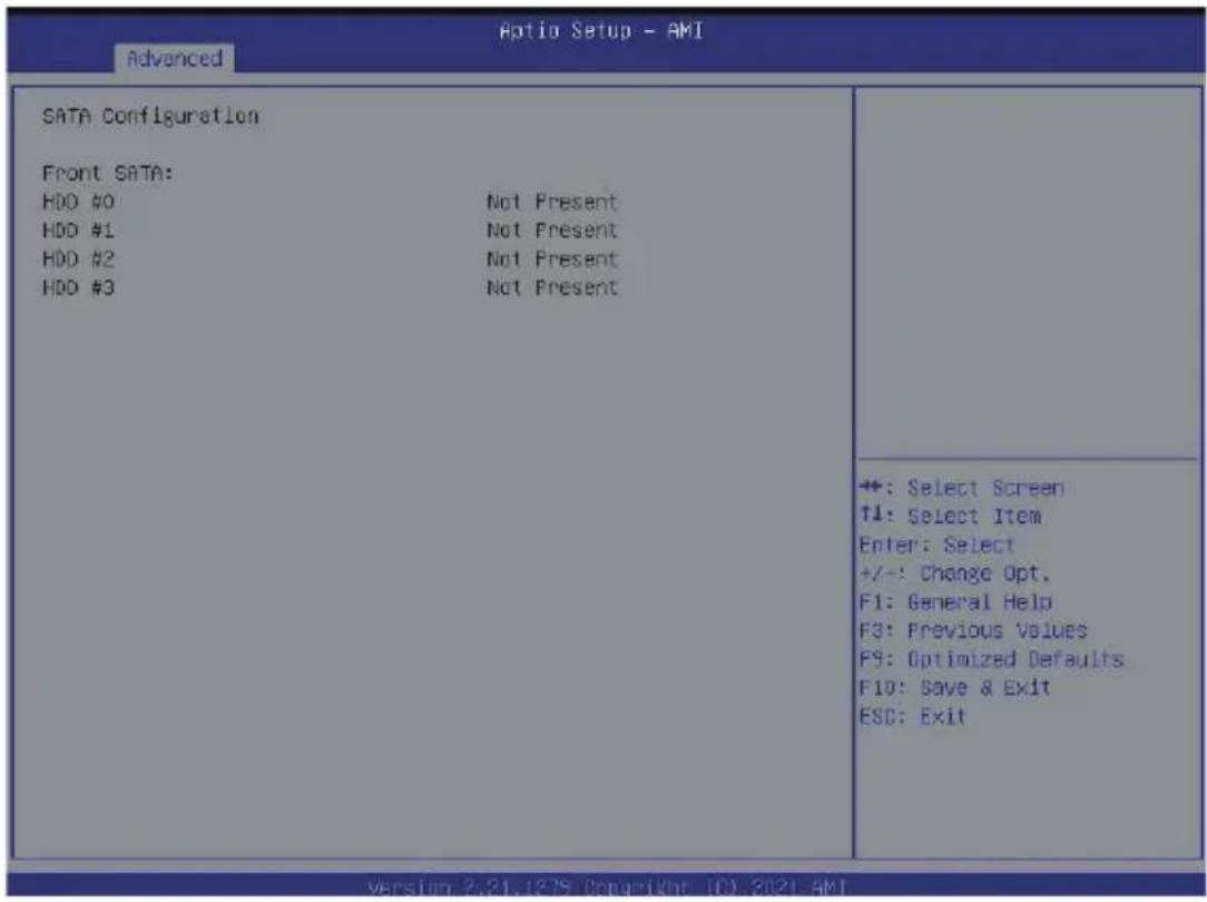
5-2-12 SATA Configuration
| Parameter | Description |
| SATA Configuration | Displays the installed HDD devices information. System will automatically detect HDD type. |
5-2-13 UEFI POST LOGO Configuration
| Optio Setup - AMI | |
| Advanced | |
| UEFI POST LOGO Configuration Output Device Type [Onboard Device] | Select Output Device Type |
| ++: Select Screen T4: Select Item Enter: Select +/-: Change Opt. F1: General Help F3: Previous Values F9: Optimized Defaults F10: Save & Exit ESC: Exit | |
| Parameter | Description |
| UEFI Configuration | |
| Output Device Type | Select output device. Options available: First loaded Device,Onboard Device,External Device, Specific Device. Default setting is Onboard Deviceevice. |
5-2-14 AMD Mem Configuration Status
| CPU 0 Mhist Test Enable Disabled, 0xC000 Mhist Aggressor Enable Disabled, 0xC000 Mhist Per Bit Slave Die Report 0x0000, 0xC000 Dram Tempo Controlled Refresh Disabled, 0xC000 Enable User Timing Mode Disabled, 0xC018 User Timing Value Disabled, 0xC018 Mem Bus Freq Limit Disabled, 0xC018 Enable Power Down Disabled, 0xC000 Dram Double Refresh Rate Disabled, 0xC000 Fmu Train Mode 0x0003, 0xC000 Eco Symbol Size 0x0002, 0xC000 Uncorrectable Ecc Retry Enabled, 0xC000 Ignore Spd Checksum Enabled, 0xC000 Enable Bank Group Swap Alt Enabled, 0xC000 Enable Bank Group Swap Disabled, 0xC01A Odr Route Balanced Tee Disabled, 0xC000 Nvdimn Power Source 0x0001, 0xC000 Odts Cmd Throt Enable Disabled, 0xC004 Odts Cmd Throt Cycle Disabled, 0xC004 | Socket-specific memory configuration status |
| **: Select Screen ↑↓: Select Item Enter: Select +/-: Change Opt. F1: General Help F3: Previous Values F9: Optimized Defaults F10: Save & Exit ESC: Exit |
| Parameter | Description |
| CPU0 | Press [Enter] to view the memory configuration status related to CPU 0. |
5-2-15 TIs Auth Configuration

Parameter Description
| Server CA Configuration | Press [Enter] for configuration of advanced items.◆ Enroll Cert- Press [Enter] to enroll a certificate• Enroll Cert Using File• Cert GUIDInput digit character in 1111111-2222-3333-4444-1234567890ab format.- Commit Changes and Exit- Discard Changes and Exit◆ Delete Cert |
| Client Cert Configuration | Press [Enter] for configuration of advanced items. |
5-2-16 Intel(R) Ethernet Controller I350
| Aptio Setup - AMI | |
| Advanced | |
| NIC Configuration | Click to configure the network device port. |
| Blink LEDs 0 | |
| UEFI Driver Intel(R) PRO/1000 6.5.21 PCI-E | |
| Adapter PDA 140422-008 | |
| Device Name Intel(R) I350 Gigabit | |
| Chip Type Network Connection | |
| PCI Device ID Intel I350 | |
| PCI Address 1521 | |
| Link Status C1:00:00 | |
| Link Status [Disconnected] | +: Select Screen T↓: Select Item Enter: Select +/-: Change Opt. F1: General Help F3: Previous Values F9: Optimized Defaults F10: Save & Exit ESC: Exit |
| MAC Address 84:2E:99:3E:7E:04 | |
| Virtual MAC Address 00:00:00:00:00 | |
| Version 2.81.1278 Copyright (C) 2021 AMI | |
| Aptio Setup - AMI | |
| Link Speed [Auto Negotiated] Make On LAN [Enabled] | Specifies the port speed used for the selected boot protocol. |
| +: Select Screen ↑↓: Select Item Enter: Select +/-: Change Opt. F1: General Help F3: Previous Values F9: Optimized Defaults F10: Save & Exit ESC: Exit | |
| Parameter | Description |
| Firmware Image Properties | Press [Enter] to configure advanced items. |
| NIC Configuration | Press [Enter] to configure advanced items.◆ Link Speed- Allows for automatic link speed adjustment.- Options available: Auto Negotiated, 10 Mbps Half, 10 Mbps Full, 100 Mbps Half, 100 Mbps Full. Default setting is Auto Negotiated.◆ Wake On LAN- Enables power on of the system via LAN. Note that configuring Wake on LAN in the operating system does not change the value of this setting, but does override the behavior of Wake on LAN in OS controlled power states.- Options available: Enabled/Disabled. Default setting is Enabled. |
| Blink LEDs | Identifies the physical network port by blinking the associated LED. Press the numeric keys to adjust desired values. |
| UEFI Driver | Displays the technical specifications for the Network Interface Controller. |
| Adapter PBA | Displays the technical specifications for the Network Interface Controller. |
| Device Name | Displays the technical specifications for the Network Interface Controller. |
| Chip Type | Displays the technical specifications for the Network Interface Controller. |
| PCI Device ID | Displays the technical specifications for the Network Interface Controller. |
| PCI Address | Displays the technical specifications for the Network Interface Controller. |
| Link Status | Displays the technical specifications for the Network Interface Controller. |
| MAC Address | Displays the technical specifications for the Network Interface Controller. |
| Virtual MAC Address | Displays the technical specifications for the Network Interface Controller. |
5-2-17 VLAN Configuration
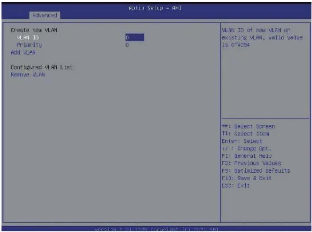
| Parameter | Description |
| Enter Configuration Menu | Press [Enter] to configure advanced items.◆ Create new VLAN◆ VLAN ID- Sets VLAN ID for a new VLAN or an existing VLAN.- Press the <+> / <-> keys to increase or decrease the desired values.- The valid range is from 0 to 4094.◆ Priority- Sets 802.1Q Priority for a new VLAN or an existing VLAN.- Press the <+> / <-> keys to increase or decrease the desired values.- The valid range is from 0 to 7.◆ Add VLAN- Press [Enter] to create a new VLAN or update an existing VLAN.◆ Configured VLAN List◆ Remove VLAN- Press [Enter] to remove an existing VLAN. |
5-2-18 MAC IPv4 Network Configuration
![Optio Setup - AKI Advanced Configured [Disabled] Save Changes and Exit Indicate whether network address configured successfully or not. +: Select Screen ↑↓: Select Item Enter: Select +/-: Change Opt. F1: General Help F3: Previous Values F9: Optimized Defaults F10: Save & Exit ESC: Exit](/content/2026/05/1109911/images/2f4e9703e28bcd31dbb4f9b3314c248fc5880c8baa893a465205ee0a6ab22afc.jpg)
| Parameter Description | |
| Configured | Indicates whether network address is configured successfully or not. Options available: Enabled/Disabled. Default setting is Disabled. |
| Enable DHCP (Note) | Options available: Enabled/Disabled. Default setting is Enabled. |
| Local IP Address (Note) | Press [Enter] to configure local IP address. |
| Local NetMask (Note) | Press [Enter] to configure local NetMask. |
| Local Gateway (Note) | Press [Enter] to configure local Gateway |
| Local DNS Servers (Note) | Press [Enter] to configure local DNS servers |
| Save Changes and Exit Press [Enter] to save all configurations. | |
(Note) This item appears when Configured is set to Enabled.
5-2-19 MAC IPv6 Network Configuration

| Parameter | Description |
| Enter Configuration Menu | Press [Enter] to configure advanced items.◆ Displays the MAC Address information.◆ Interface ID- The 64 bit alternative interface ID for the device. The string is colon separated. e.g. ff:dd:88:66:cc:1:2:3.◆ DAD Transmit Count- The number of consective Neighbor solicitation messages sent while performing Duplicate Address Detection on a tentative address.A value of zero indicates that Duplicate Address Detection is not performed.◆ Policy- Options available: automatic/manual. Default setting is automatic.◆ Save Changes and Exit- Press [Enter] to save all configurations. |
5-3 AMD CBS Menu
AMD CBS menu displays submenu options for configuring the CPU-related information that the BIOS automatically sets. Select a submenu item, then press [Enter] to access the related submenu screen.
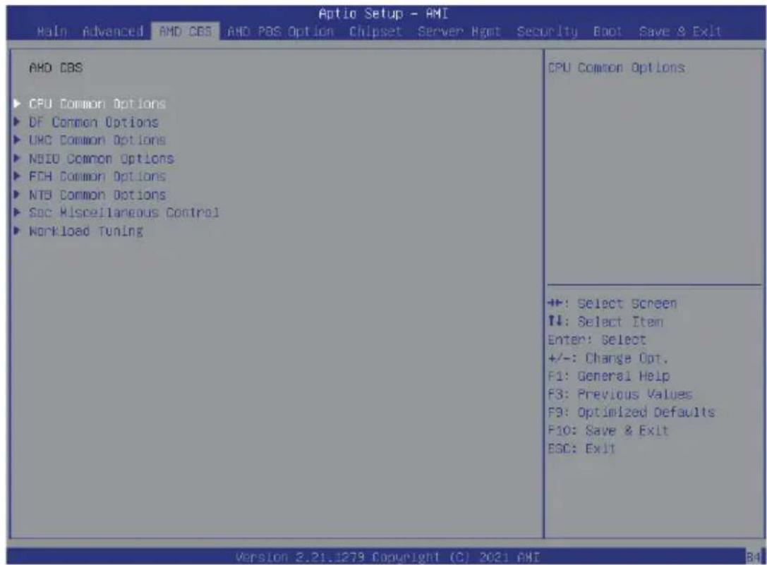
5-3-1 CPU Common Options
![CPU Common Options ► Performance ► Prefetcher settings ► Core Watchdog RedirectForReturnDis [Auto] Platform First Error Handling [Auto] Core Performance Boost [Auto] Global C-state Control [Auto] Power Supply Idle Control [Auto] SEV ASID Count [Auto] SEV-ES ASID Space Limit Control [Auto] Streaming Stores Control [Auto] Local APIC Mode [Auto] ACPI _OST CI Declaration [Auto] MCA error thresh enable [Auto] SMU and PSP Debug Mode [Auto] King7 Workaround [Auto] PPIN Opt-in [Auto] SNP Memory (RHP Table) Coverage [Auto] SMEE [Auto] Action on BIST Failure [Auto] Fast Short REP MOVSB [Enabled] Enhanced REP MOVSB/STOSB [Enabled] Performance +: Select Screen T4: Select Item Enter: Select +/-: Change Opt. F1: General Help F3: Previous Values F9: Optimized Defaults F10: Save & Exit ESD: Exit Version 2.21.1279 Copyright (C) 2021 AMI](/content/2026/05/1109911/images/a7e42be3c7aa03d1e40d326edd2172b74c84bb411010a9692da44e74ee7de621.jpg)
Parameter Description
| CPU Common Options | |
| Performance Press [Enter] for configuration of advanced items. | |
| Prefetcher settings Press [Enter] for configuration of advanced items. | |
| Core Watchdog Press [Enter] for configuration of advanced items. | |
| RedirectForReturnDis | From a workaround for GCC/C000005 issue for XV Core on CZ A0, setting MSRC001_1029 Decode Configuration (DE_CFG) bit 14 [DecfgNoRdrctForReturns] to 1. Options available: Auto, 1, 0. Default setting is Auto. |
| Platform First Error Handling | Enable/Disable PFEH, cloak individual banks, and mask deferred error interrupts from each bank. Options available: Auto, Enabled, Disabled. Default setting is Auto. |
| Core Performance Boost | Enable/Disable the Core Performance Boost function. Options available: Auto/Disabled. Default setting is Auto. |
| Global C-State Control | Controls the IO based C-state generation and DF C-states. Options available: Auto, Enabled, Disabled. Default setting is Auto. |
| Power Supply Idle Control | Configures the Power Supply Idle Control. Options available: Auto, Low Current Idle, Typical Current Idle. Default setting is Auto. |
| SEV ASID Count | Specifies the maximum valid ASID, which affects the maximum system physical address space. Options available: Auto, 253 ASIDs, 509 ASIDs. Default setting is Auto. |
| Parameter Description | |
| SEV-ES ASID Space Limit Control | Space limit control for SEV-ES ASIDs.Options available: Auto/Manual. Default setting isAuto. |
| Streaming Stores Control | Enable/Disable the Streaming Stores functionality.Options available: Auto, Enabled, Disabled. Default setting isAuto. |
| Local APIC Mode | Sets the Local APIC Mode.Options available: Auto, xAPIC, x2APIC. Default setting isAuto. |
| ACPI_CST C1 Decaration | Determines whether or not to declare the C1 state to the OS..Options available: Auto, Enabled, Disabled. Default setting isAuto. |
| MCA error thresh enable | Enable MCA error thresholding.Options available: Auto, False, True. Default setting isAuto. |
| SMU and PSP Debug Mode | When this option is enabled, specific uncorrected errors detected by the PSP FW or SMU FW will hand and not reset the system.Options available: Auto, Enabled, Disabled. Default setting isAuto. |
| Xtrig7 Workaround | Options available: Auto, No Workaround, Bronze Workaround, Sliver Workaround. Default setting isAuto. |
| PPIN Opt-in | Enable/Disable the PPIN feature.Options available: Auto, Enabled, Disabled. Default setting isAuto. |
| SNP Memory (RMP Table) Coverage | Enabled: Enter system memory is covered.Options available: Auto, Enabled, Disabled, Custom.Default setting isAuto. |
| SMEE | Control secure memory encryption enable.Options available: Auto, Enabled, Disabled.Default setting isAuto. |
| Action on BIST Failure | Action to take when a CCD BIST failure is detected.Options available: Auto, Do nothing, Down-CCD.Default setting isAuto. |
| Fast Short REP MOVSB | Default is 1, cab be set to zero for analysis purpose as long as OS supports it.Options available: Enabled, Disabled.Default setting isEnabled. |
| Enhanced REP MOVSB/ STOSB | Default is 1, cab be set to zero for analysis purpose as long as OS supports it.Options available: Enabled, Disabled.Default setting isEnabled. |
| REP-MOV/STOS Steaming | Allows REP-MOV/STOS to use non-caching streaming stores for large sizes.Options available: Enabled, Disabled.Default setting isEnabled. |
| X3D | Override of X3D technology.Options available: Auto, Disable, 1 stack, 2 stack, 4 stack.Default setting isAuto. |
| IBS hardware work around | Set if using IBS execution sampling without software workaround for erratum 1,285. May impac performance..Options available: Enabled, Auto.Default setting isEnabled. |
5-3-1-1 Performance
![Aptio Setup - AMI AMD CBS Performance OC Mode ► Custom Core Pstates ► OCD/Core/Thread Enablement SMT Control [Normal Operation] [Disable] No help string +: Select Screen TI: Select Ttem Enter: Select +/-: Change Opt. F1: General Help F3: Previous Values F9: Optimized Defaults F10: Save & Exit ESG: Exit version 2.21.1279 Copyright (C) 2021 AMI](/content/2026/05/1109911/images/55fa47a8d29b00eabfe4228c6c61f4a2047e866277d1ed3ea7094b9825ff87d9.jpg)
Parameter Description
| Performance | |
| OC Mode (Note1) | Option Available: Normal Operation, CustomizedDefault setting is Normal Operation. |
| Custom Core Pstates | Allows you to accept or decline enabling Custom Core Pstates. When accepted, you can disable or customize core pstates. |
| CCD/Core/Thread Enablement | Allows you to accept or decline enabling CCDs, processor cores and threads. When accepted, you can control the number of CCDs to be used, the number of cores to be used, and whether to enable or disable Simultaneous Multithreading Technology (SMT) support. |
| SMT Control | Can be used to disable symmetric multithreading. To re-enable SMT, a Power CYCLE is needed after select the 'Enable' option. Select 'Auto' base on BIOS PCD. (PcdAmdSmtMode) default setting.Option Available: Enable, Disable.Default setting is Disable. |
(Note1) Advanced items are configurable when this item is defined.
5-3-1-2 Prefetcher Settings
![Aptio Setup - AMI AMO CBS Prefetcher settings L1 Stream HW Prefetcher [Enable] L1 Stride Prefetcher [Auto] L1 Region Prefetcher [Auto] L2 Stream HW Prefetcher [Enable] L2 Up/Down Prefetcher [Auto] Option to Enable | Disable L1 Stream HW Prefetcher +: Select Screen T↓: Select Item Enter: Select +/-: Change Opt. F1: General Help F9: Previous Values F9: Optimized Defaults F10: Save & Exit ESC: Exit Version 2.21.1275 Copyright (C) 2021 AMI](/content/2026/05/1109911/images/807587fa09c9b59dbb1a786f16414e5728dd7239d596311658ec88f71649da72.jpg)
| Parameter Description | |
| Prefetcher settings | |
| L1 Stream HW Prefetcher | Enable/Disable L1 Stream HW Prefetcher.Options available: Auto, Enable, Disabled. Default setting is Enable. |
| L1 Stride Prefetcher | Use memory access history of individual instruction to fetch additional linesEnable/Disable L1 Stream HW Prefetcher.Options available: Auto, Enable, Disable. Default setting is Auto. |
| L1 Region Prefetcher | Use memory access history to fetch additional lines when the data access for a given instruction tends to be followed by other data accesses.Options available: Auto, Enable, Disable. Default setting is Enable. |
| L2 Stream HW Prefetcher | Enable/Disable L2 Stream HW Prefetcher.Options available: Auto, Enable, Disabled. Default setting is Enable. |
| L2 Up/Down Prefetcher | Use memory access history to determine whether to fetch the next or previous line for all memory accesses. .Options available: Auto, Enable, Disable. Default setting is Auto. |
5-3-1-3 Core Watchdog
![Optio Setup - AMI AMD COS Core Watchdog Core Watchdog Timer Enable [Auto] Enable or disable CPU Watchdog Timer +: Select Screen F1: Select Item Enter: Select +/-: Change Opt. F1: General Help F3: Previous Values F9: Optimized Defaults F10: Save & Exit ESC: Exit version 2.21.1279 Copyright (C) 2021 AMI](/content/2026/05/1109911/images/a799bae032d0c51813af3a1e0a78b7894135f0257616e2e96c7a091751ef4a4c.jpg)
Parameter Description
| Core Watchdog | |
| Core Watchdog Timer Enable | Enable/Disable CPU Watchdog Timer. |
| Options available: Auto, Enabled, Disabled. Default setting is Auto. | |
5-3-2 DF Common Options
![Aptio Setup - AMI AMD CBS DF Common Options ► Scrubber ► Memory Addressing ► ACPI ► Link Disable DF to external IP [Auto] SyncFloodPropagation Disable DF sync flood propagation [Auto] Freeze DF module queues on error [Auto] CCB memory region encryption [Auto] System probe filter [Auto] Memory Clear [Auto] PSP error injection support [False] Scrubber ++: Select Screen T↓: Select Item Enter: Select +/-: Change Opt. F1: General Help F3: Previous Values F9: Optimized Defaults F10: Save & Exit ESC: Exit Version 2.21.1279 Copyright (C) 2021 AMI 84](/content/2026/05/1109911/images/57ae8e51dd52e9f1ef6eb8ce0096f16dd981ab3779965b428e7f60c1ccf94ab6.jpg)
Parameter Description
| DF Common Options | |
| Scrubber Press [Enter] for configuration of advanced items. | |
| Memory Addressing Press [Enter] for configuration of advanced items. | |
| ACPI Press [Enter] for configuration of advanced items. | |
| Link Press [Enter] for configuration of advanced items. | |
| Disable DF to external IP sync flood propagation | Enable/Disable SyncFlood to UMC & downstream slaves. Options available: Auto, Sync flood disabled, Sync flood enabled. Default setting is Auto. |
| Disable DF sync flood propagation | Enable/Disable DF Sync Flood propagation. Options available: Auto, Sync flood disabled, Sync flood enabled. Default setting is Auto. |
| Frezze DF module queues on error | Options available: Auto, Enabled, Disabled. Default setting is Auto. |
| CC6 memory region encryption | Controls whether or not the CC6 save/restor memory is encrypted. Options available: Auto, Enabled, Disabled. Default setting is Auto. |
| System probe filter | Enable/Disable Systme probe filter. Options available: Auto, Enabled, Disabled. Default setting is Auto. |
| Memory Clear | Enable/Disable the Memory Clear feature. Options available: Auto, Enabled, Disabled. Default setting is Auto. |
| PSP error injection support | Enable/Disable PSP error injection support. Options available: False/True. Default setting is False. |
5-3-2-1 Scrubber
![Optio Setup - AMI AMD CBS Scrubber DRAM scrub time [Auto] Poison scrubber control [Auto] Redirect scrubber control [Auto] Redirect scrubber limit [Auto] Provide a value that is the number of hours to scrub memory. ++: Select Screen ↑↓: Select Item Enter: Select +/-: Change Opt. F1: General Help F3: Previous Values F9: Optimized Defaults F10: Save & Exit ESC: Exit Version 2.21.1279 Copyright (C) 2021 AMI](/content/2026/05/1109911/images/46a53e96579e2ed77358a8c5042832f34a53346fdf2f5f1f61e7150b87a09bb1.jpg)
Parameter Description
| Scrubber | |
| DRAM scrub time | Provide a value that is the number of hours to scrub memory. Options available: Auto, Disabled, 1 hour, 4 hours, 8 hours, 16 hours, 24 hours, 48 hours. Default setting isAuto. |
| Poison scrubber control | Enable/Disable the Poison scrubber control feature. Options available: Auto, Enabled, Disabled. Default setting isAuto. |
| Redirect scrubber control | Enable/Disable the Redirect scrubber control feature. Options available: Auto, Enabled, Disabled. Default setting isAuto. |
| Redirect scrubber limit | Sets the redirect scrubber limit. Options available: Auto, 2, 4, 8, Infinite. Default setting isAuto. |
5-3-2-2 Memory Addressing
![Memory Addressing NUMA nodes per socket [Auto] Memory interleaving [Auto] Memory interleaving size [Auto] 1TB remop [Auto] DRAM map inversion [Auto] Location of private memory regions [Auto] Specifies the number of desired NUMA nodes per socket. Zero will attempt to interleave the two sockets together. ++: Select Screen +/-: Select Item Enter: Select +/-: Change Opt. F1: General Help F3: Previous Values F9: Optimized Defaults F10: Save & Exit ESO: Exit version 2.21.1879 Copyright (C) 2021 AMI](/content/2026/05/1109911/images/948229a2dbbb1fe89e13c92804403ccf55fe3df1e3c135a4c6a2910f2378dd64.jpg)
| Parameter Description | |
| Memory Addressing | |
| NUMA nodes per socket | Specifies the number of desired NUMA nodes per socket.Options available: Auto, NPS0, NPS1, NPS2, NPS4. Default setting is NPS4. |
| Memory inerleaving | Enable/Disable the Memory interleaving feature.Options available: Auto/Disabled. Default setting is Auto. |
| Memory interleaving size | Controls the memory interleaving size. This determines the starting address of the interleave (bit 8, 9, 10 or 11).Options available: Auto, 256Bytes, 512Bytes, 1KB, 2KB. Default setting is Auto. |
| 1TB remap | Enable/Disable to remap DRAM out of the space just below the 1TB boundary.The ability to remap depends on DRAM configuration, NPS, and interleaving selection, and may not always be possible.Options available: Auto, Do not remap, Attempt to remap.Default setting is Auto. |
| DRAM map inversion | Enable/Disable the DRAM map inversion function.Options available: Auto, Enabled, Disabled. Default setting is Auto. |
| Location of private memory regions | Control whether or not the rpivate memory regions (PSP, SMU, and CC6) are at the top of DRAM or distributed. Note that distributed requires memory on all dies. Note that it will always be at the top of DRAM if some dies don't have memory regardless of this.Options available: Auto, Distributed, Consolidated. Default setting is Auto. |
5-3-2-3 ACPI
![Aptio Setup - AMI AMD CDS ACPI ACPI SRAT L9 Cache As NUMA Domain [Auto] ACPI SLIT Distance Control [Auto] ACPI SLIT remote relative distance [Auto] Enabled: Each CCX in the system will be declared as a separate NUMA domain. Disabled: Memory Addressing \ NUMA nodes per socket will be declared. ++: Select Screen ↑↓: Select Item Enter: Select +/-: Change Opt. F1: General Help F3: Previous Values F9: Optimized Defaults F10: Save & Exit ESC: Exit Version 2.21.1279 Copyright (C) 2021 AMI](/content/2026/05/1109911/images/f89c2105ec2a860831952b8b0701be319a8fe95eb656c4977a8bb5c300370a3e.jpg)
| Parameter Description | |
| ACPI | |
| ACPI SRAT L3 Cache As NUMA Domain | Enable/Disable the ACPI SRAT L3 Cache As NUMA Domain function.Options available: Auto, Enabled, Disabled. Default setting isAuto. |
| ACPI SLIT Distance Control | Determines how the SLIT distances are declared.Options available: Auto/Manual. Default setting isAuto. |
| ACPI SLIT remote relative distance | Sets the remote socket distance for 2P systems as near (2.8) or far (3.2).Options available: Auto, Near, Far. Default setting isAuto. |
5-3-2-4 Link
![Optio Setup - AMI AMD CBS Link GMI encryption control [Auto] xGMI encryption control [Auto] CAKE CRC perf bounds Control [Auto] xGMI Link Configuration [Auto] 4-1link xGMI max speed [Auto] 3-1link xGMI max speed [Auto] xCMI TXEQ Mode [Auto] xCMI 10GACOFC [Auto] Control GMI link encryption ++: Select Screen ↑↓: Select Item Enter: Select +/-: Change Opt. F1: General Help F3: Previous Values F9: Optimized Defaults F10: Save & Exit ESC: Exit Version 2.21.1279 Copyright (C) 2021 AMI](/content/2026/05/1109911/images/ff5320e99a0dae762c00665e99ed3bfe6eb2324e01b74e97d2eb3ba2111c21d6.jpg)
| Parameter Description | |
| Link | |
| GMI encryption control | Enable/Disable GMI link encryption. Options available: Auto, Enabled, Disabled. Default setting isAuto. |
| xGMI encryption control | Enable/Disable xGMI link encryption. Options available: Auto, Enabled, Disabled. Default setting isAuto. |
| CAKE CRC perf bounds Control | Options available: Auto/Manual. Default setting isAuto. |
| 4-link xGMI max speed | Specifies the max speed of 4-link xGMI. Options available: Auto, 10.667Gbps, 13Gbps, 16Gbps, 18Gbps. Default setting is10.667Gbps. |
| 3-link xGMI max speed | Specifies the max speed of 3-link xGMI. Options available: Auto, 10.667Gbps, 13Gbps, 16Gbps, 18Gbps. Default setting is10.667Gbps. |
| xGMI TXEQ Mode | Configures xGMI TXEQ/RX vetting Mode. Options available: Auto, TXEQ_Disabled, TXEQ_Lane, TXEQ_Link, TXEQ_RX_Vet. Default setting is10.667Gbps. |
| xGMI 18GACOFC | Configures xGMI 18GACOFC. Options available: Auto, Enable, Disable. Default setting isAuto. |
5-3-3 UMC Common Options
| Optio Setup - AMI AMD CBS | |
| UMC Common Options ► DDR4 Common Options ► DRAM Memory Mapping ► NVDIMM ► Memory MOIST | DDR4 Common Options |
| +/-: Select Screen 11: Select Item Enter: Select +/-: Change Opt. F1: General Help F3: Previous Values F3: Optimized Defaults F10: Save & Exit ESC: Exit | |
| Version 2.21.1279 Copyright (C) 2021 AMI | |
Parameter Description
UMC Common Options
DDR4 Common Options Press [Enter] for configuration of advanced items.
DRAM Memory Mapping Press [Enter] for configuration of advanced items.
NVDIMM Press [Enter] for configuration of advanced items.
Memory MBIST Press [Enter] for configuration of advanced items.
5-3-3-1 DDR4 Common Options

Parameter Description
DDR4 Common Options
| Enforce POR | Press [Enter] to configure the Plan of Record (POR) to enable / disable restrictions for DDR4 frequency and voltage programming. Memory speeds will be capped at AMD guidelines.Note: To enable 2 DIMMs per Channel at 3200MHz function, select [Accept] at warning message, change Overclock from [Auto] to [Enabled], and then set memory speed to 3200MHz. |
DRAM Controller Configuration Press [Enter] to configure DRAM Controller Configuration.
CAD Bus Configuration Press [Enter] to configure CAD Bus Configuration.
Data Bus Configuration Press [Enter] to configure Data Bus Configuration.
Common RAS Press [Enter] to configure Common RAS.
Security Press [Enter] to configure Security.
Phy Configuration Press [Enter] to configure Security.
5-3-3-1-1 DRAM Controller Configuration
![Aptio Setup - AMI AMD CES DRAM Controller Configuration ▶ DRAM Power Options Cmd2T [Auto] Gear Down Mode [Auto] DRAM Power Options +: Select Screen T1: Select Item Enter: Select +/-: Change Dot. F1: General Help F3: Previous Values F9: Optimized Defaults F10: Save & Exit ESC: Exit Version 2.21.1279 Copyright (C) 2021 AMI](/content/2026/05/1109911/images/fcd96197dd3e365bceb5f2fefebca286a6f0a78f09c30951757a3be912caeee8.jpg)
Parameter Description
DRAM Controller Configuration
| DRAM Power Options | Press [Enter] to configure DRAM Power OptionsMa.◆ Power Down Enable- Enable/Disable DDR power down mode.- Options available: Auto, Enabled, Disabled. Default setting isAuto.◆ Power Down Entry Delay◆ SubUrgRefLowerBound◆ UrgRefLimit◆ DRAM Maximum Activate Count- Options available: Auto, Unlimited MC, 200K,300K, 400K, 500K,600K, 700K. Default setting isAuto.◆ DRAM Refresh Rate- Options available: 7.8 usec, 3.9 usec. Default setting is7.8 usec.◆ Self-Refresh Exit Staggering- Options available:Disabled, Trfc/3, Trfc/4. Default setting isDisabled. |
| Cmd2T | Selects the Cmd2T mode on ADDR/CMD.Options available: Auto, 1T, 2T. Default setting isAuto. |
| Gear Down Mode | Enable/Disable the Gear Down Mode function.Options available: Auto, Enabled, Disabled. Default setting isAuto. |
5-3-3-1-2 CAD Bus Configuration
![ADN CBS Aptio Setup - AMI CAD Bus Configuration CAD Bus Timing User Controls [Auto] CAD Bus Drive Strength User [Auto] Controls Setup time on DAD bus signals to Auto or Manual +#: Select Screen +#: Select Item Enter: Select +/-: Change Opt. F1: General Help F3: Previous Values F9: Optimized Defaults F10: Save & Exit ESC: Exit Version 2.21.1279 Copyright (C) 2021 AMI](/content/2026/05/1109911/images/2a42a23cda0f13a3cffd5329376875eaab7fdf0ee091b2bad39b32dea38d3179.jpg)
Parameter Description
| CAD Bus Configuration | |
| CAD Bus Timing User Controls | Setup time on CAD bus signals to Auto or Manual. Options available: Auto/Manual. Default setting isAuto. |
| CAD Bus Drive Strength User Controls | Drive Strength on CAD bus signals to Auto or Manual. Options available: Auto/Manual. Default setting isAuto. |
5-3-3-1-3 Data Bus Configuration
![Aptio Setup - AMI AMD: CBS Data Bus Configuration Data Bus Configuration User [Auto] Controls Specify the mode for drive strength to Auto or Manual +: Select Screen ↑↓: Select Item Enter: Select +/-: Change Opt. F1: General Help F3: Previous Values F9: Optimized Defaults F10: Save & Exit ESC: Exit Version 2.21.1279 Copyright (C) 2021 AMI](/content/2026/05/1109911/images/8e6d848465c53656faba5dc73641ede8c7b90a74467bdc48a1507d580726753d.jpg)
Parameter Description
| Data Bus Configuration | |
| Data Bus Configuration User Controls | Specifies the mode for drive strength to Auto or Manual. Options available: Auto/Manual. Default setting isAuto. |
5-3-3-1-4 Common RAS
![Aptio Setup - AMI AMD: CES Common RAS Data Poisoning [Auto] DRAM Post Package Repair [Disable] BCD Parity [Auto] DRAM Address Command Parity Retry [Auto] Max Parity Error Replay 8 Write CRC Enable [Auto] DRAM Write CRC Enable and Retry [Auto] Limit Max Write CRC Error Replay 8 Disable Memory Error Injection [True] ▶ ECO Configuration Enable/disable data poisoning: UMC_CH::EccCtrl1[UcFatalEn] UMC_CH::EccCtrl1[MrEccEn] Should be enabled/disabled together. **: Select Screen T4: Select Item Enter: Select +/-: Change Opt. F1: General Help F3: Previous Values F9: Optimized Defaults F10: Save & Exit ESC: Exit version 2.21.1279 Copyright (C) 2021 AMI](/content/2026/05/1109911/images/faaed3fddba6ef720fc8bf7f23e4b0bbf9c296a20fffce5b9807eedc1a7acfb0.jpg)
| Parameter Description | |
| Common RAS | |
| Data Poisoning | Enable/Disable the Data Poisoning function.Options available: Auto, Enabled, Disabled. Default setting isAuto. |
| DRAM Post Package Repair | Enable/Disable the DRAM Post Package Repair function.Options available: Enabled/Disabled. Default setting isAuto. |
| RCD Parity | Enable/Disable the RCD Parity function.Options available: Auto, Enabled, Disabled. Default setting isAuto. |
| DRAM Address Command Parity Retry | Enable/Disable the DRAM Address Command Parity Retry function.Options available: Auto, Enabled, Disabled. Default setting isAuto. |
| Max Parity Error Replay | Configures the Max Parity Error Replay. (0~0x3f)Default setting is8.Please note that this item is configurable when DRAM Address Command Parity Retry is set to Enabled. |
| Write CRC Enable | Enable/Disable the Write CRC function.Options available: Auto, Enabled, Disabled. Default setting isAuto. |
| DRAM Write CRC Enable and Retry Limit | Enable/Disable DRAM Write CRC Enable and Retry Limit.Options available: Auto, Enabled, Disabled. Default setting isAuto. |
| Max Write CRC Error Replay | Configures the Max Write CRC Error Replay. (0~0x3f)Default setting is8.Please note that this item is configurable when DRAM Write CRC Enable and Retry Limit is set to Enabled. |
| Disable Memory Error Injection | Options available: False/True. Default setting is True. |
| ECC Configuration | Press [Enter] to configure advanced items.♦ DRAM ECC Symbol Size– Configures the DRAM ECC Symbol Size.– Options available: Auto, x4, x8, x16. Default setting is Auto.♦ DRAM ECC Enable– Enable/Disable DRAM ECC. When set to Auto, it will set ECC to enable.– Options available: Auto, Enabled, Disabled. Default setting is Auto.♦ DRAM UECC Retry– Enable/Disable DRAM UECC Retry.– Options available: Auto, Enabled, Disabled. Default setting is Auto. |
5-3-3-1-5 Security
![AHD CBS Security TSME [Auto] Data Scramble [Auto] Transparent SRE: AddrTweakEn = 1; ForceEncrEn =1; DataEncrEn = 0 ++: Select Screen ↑↓: Select Item Enter: Select +/-: Change Opt. F1: General Help F3: Previous Values F9: Optimized Defaults F10: Save & Exit ESC: Exit Version 2.21.1279 Copyright (C) 2021 AHI](/content/2026/05/1109911/images/bca5205f711f8667ddc434411e501840aece7b23d3f621afad5d00ae39f4d539.jpg)
Parameter Description
| Security | |
| TSME | Enable/Disable Transparent SME. Options available: Auto, Enabled, Disabled. Default setting is Auto. |
| Data Scramble | Enable/Disable Data Scrambling. Options available: Auto, Enabled, Disabled. Default setting is Auto. |
5-3-3-1-6 Phy Configuration
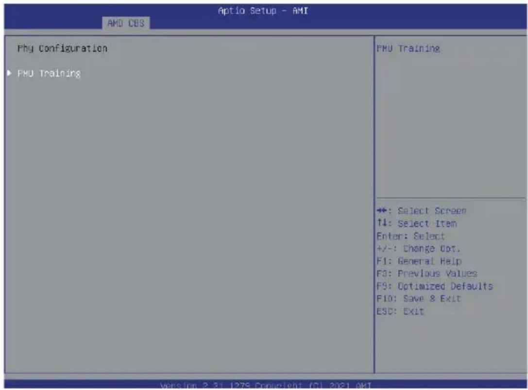
Parameter Description
Phy Configuration
| PMU Training | Press [Enter] to configure PMU Training.♦ DFE Traing- Enable/Disable DDR power down mode.- Options available: Auto, Enabled, Disabled. Default setting isAuto.♦ FFE Write Training-Auto, Enabled, Disabled. Default setting isAuto.♦ PMU Pattern Bits Controls-Auto, Manual. Default setting isAuto. |
5-3-3-2 DRAM Memory Mapping
![AOTIO Setup - AMI AND CBS DRAM Memory Mapping Chipselect Interleaving [Auto] BankGroupSwap [Auto] BankGroupSwapAlt [Auto] Address Hash Bank [Auto] Address Hash CS [Auto] Address Hash Rx [Auto] SPD Read Optimization [Auto] Interleave memory blocks across the DRAM chip selects for node 0. ++: Select Screen ↑↓: Select Item Enter: Select +/-: Change Opt. F1: General Help F3: Previous Values F9: Optimized Defaults F10: Save & Exit ESC: Exit Version 2.21.1279 Copyright (C) 2021 AMI](/content/2026/05/1109911/images/6ad2bf745095e60f14d1d1a68a0777153a218bb4430f6896cabe40b0a975552f.jpg)
| Parameter Description | |
| DRAM Memory Mapping | |
| Chipselect Interleaving | Interleave memory blocks across the DRAM chip selects for CPU 0. Options available: Auto/Disabled. Default setting is Auto. |
| BankGroupSwap | Configures the BankGroupSwap. BankGroupSwap (BGS) is a new memory mapping option in AGESA that alters how applications get assigned to physical locations within the memory modules. When this option sets to Auto, it is null: No help string. Options available: Auto, Enabled, Disabled. Default setting is Auto. |
| BankGroupSwapAlt | Configures the BankGroupSwapAlt. Options available: Auto, Enabled, Disabled. Default setting is Auto. |
| Address Hash Bank | Enable/Disable bank address hashing. Options available: Auto, Enabled, Disabled. Default setting is Auto. |
| Address Hash CS | Enable/Disable CS address hashing. Options available: Auto, Enabled, Disabled. Default setting is Auto |
| Address Hash Rm | Enable/Disable RM address hashing. Options available: Auto, Enabled, Disabled. Default setting is Auto |
| SPD Read Optimization | Enable/Disable SPD Read Optimization. Options available: Auto, Enabled, Disabled. Default setting is Auto |
5-3-3-3 NVDIMM
![Aptio Setup - AMI AMD: CBS NVDIMM Disable NVDIMH-N Feature [No] Disable NVDIMH-N feature for memory margin tool +: Select Screen ↑↓: Select Item Enter: Select +/-: Change Opt. F1: General Help F3: Previous Values F9: Optimized Defaults F10: Save & Exit ESC: Exit Version 2.31.1279 Copyright (C) 2021 AMI](/content/2026/05/1109911/images/77f3c1a1511e0d6bbb1fecb2a46e34e59a706bcfb9dd5e49f88a213536037095.jpg)
| Parameter | Description |
| NVDIMM | Disable NVDIMM-N feature for memory margin tool. Options available: No, Yes. Default setting is No. |
5-3-3-4 Memory MBIST
![AHD CBS Memory MBIST MBIST Enable [Disabled] MBIST Test Mode [Auto] MBIST Aggressors [Auto] MBIST Per Bit Slave Die Reporting [Auto] Data Eye Memory Healing BIST [Disabled] Hem BIST Test Select [Vendor Tests Enabled] Hem BIST Post Package Repair Type [Soft Repair] Enable or disable Memory MBIST +: Select Screen T1: Select Item Enter: Select +/-: Change Opt. F1: General Help F3: Previous Values F9: Optimized Defaults F10: Save & Exit ESC: Exit Version 2.21.1279 Copyright (C) 2021 AMI](/content/2026/05/1109911/images/5d3c6cfe5426d30d84cab9c0f7fe0c64b232e13c572aee099db83679ebe7e7f1.jpg)
| Parameter | Description |
| Memory MBIST | |
| MBIST Enable | Enable/Disable the Memory MBIST function.Options available: Enabled/Disabled. Default setting is Disabled. |
| MBIST\ Test\ Mode(Note) | Selects MBIST Test Mode.Interface Mode: Tests Single and Multiple CS transactions and Basic Connectivity.Data Eye Mode: Measures Voltage vs. Timing.Options available: Auto, Both, Interface Mode, Data Eye Mode. Default setting is Auto. |
| MBIST\ Aggressors(Note) | Enable/Disable MBIST Aggressor test.Options available: Auto, Enabled, Disabled. Default setting is Auto. |
| MBIST Per Bit Slave Die Reporting (Note) | Enable/Disable to report 2D data eye results in ABL log for each DQ, Chipselect, and Channel.Options available: Auto, Enabled, Disabled. Default setting is Auto. |
| Data Eye | Press [Enter] to configure advanced items. |
| Memory Healing BIST | Enable/Disable memory healing BIST.Options available: Auto, Enabled, Disabled. Default setting is Disabled. |
(Note) This item appears when MBIST Enable is set to Enabled.
5-3-3-4-1 Data Eye
| Data Eye | No help string | |
| Pattern Select Pattern Length Aggressor Channel Aggressor Static Lane Control Aggressor Static Lane Select Upper 32 bits Aggressor Static Lane Select Lower 32 Bits Aggressor Static Lane Select ECC Aggressor Static Lane Value Target Static Lane Control Target Static Lane Select Upper 32 bit Target Static Lane Select Lower 32 Bits Target Static Lane Select ECC Target Static Lane Value Worst Case Margin Granularity Read Voltage Sweep Step Size Read Timing Sweep Step Size Write Voltage Sweep Step Size Write Timing Sweep Step Size | [PRBS] 3 [1 Aggressor Channel] [Disabled] 0 0 0 [Disabled] 0 0 0 [Per Chip Select] [1] [1] [1] | |
| +: Select Screen T↓: Select Item Enter: Select +/-: Change Opt. F1: General Help F3: Previous Values F8: Optimized Defaults F10: Save & Exit ESC: Exit |
| Parameter | Description |
| Data Eye | |
| Pattern Select | Options available: PRBS, SSO, Both. Default setting is PRBS. |
| Pattern Length | Determines the pattern length. The possible options are N=3....12. |
| Aggressor Channel | This item helps read the aggressors channels. Options available: Disabled, 1 Aggressor Channel, 3 Aggressor Channels, 7 Aggressor Channels. Default setting is 1 Aggressor Channel. |
| Aggressor Static Lane Control | Enable/Disable the Aggressor Static Lane Control function. Options available: Enabled/Disabled. Default setting is Disabled. |
| Aggressor Static Lane Select Upper 32 bits | This item is configurable when Aggressor Static Lane Control is set to Enabled. |
| Aggressor Static Lane Select Lower 32 bits | This item is configurable when Aggressor Static Lane Control is set to Enabled. |
| Aggressor Static Lane Select ECC | This item is configurable when Aggressor Static Lane Control is set to Enabled. |
| Aggressor Static Lane Value | This item is configurable when Aggressor Static Lane Control is set to Enabled. |
| Target Static Lane Control | Enable/Disable the Target Static Lane Control function. Options available: Enabled/Disabled. Default setting is Disabled. |
| Target Static Lane Select Upper 32 bits | This item is configurable when Target Static Lane Control is set to Enabled. |
| Target Static Lane Select Lower 32 bits | This item is configurable when Target Static Lane Control is set to Enabled. |
| Target Static Lane Select ECC | This item is configurable when Target Static Lane Control is set to Enabled. |
| Target Static Lane Value | This item is configurable when Target Static Lane Control is set to Enabled. |
| Data Eye Type | This item determines which results are expected to be captured for Data Eye. Options available: 1D Voltage Sweep, 1D Timing Sweep, 2D Full Data Eye, Worst Case Margin Only. Default setting is Worst Case Margin Only. |
| Worst Case Margin Granularity | Configures Worst Case Margin Granularity. Options available: Per Chip Select, Per Nibble. Default setting is Worst Case Margin Only. |
| Read Voltage Sweep Step Size | Configures the step size for read Data Eye voltage sweep. Options available: 1, 2, 4. Default setting is 2. |
| Read Timing Sweep Step Size | Configures the step size for read Data Eye timing sweep. Options available: 1, 2, 4. Default setting is 1. |
| Write Voltage Sweep Step | Configures the step size for write Data Eye voltage sweep. Options available: 1, 2, 4. Default setting is 2. |
| Write Timing Sweep Step Size | Configures the step size for write Data Eye timing sweep. Options available: 1, 2, 4. Default setting is 1. |
5-3-4 NBIO Common Options
![Ampio Setup - AMI AMD CBS SMU Common Options Power Policy Quick Setting [Best Performance] Determinism Control [Manual] Determinism Slider [Power] CTDP Control [Manual] CTDP 290 EfficiencyModeEn [Auto] Package Power Limit Control [Manual] Package Power Limit 280 XGMI Link Width Control [Auto] APBDTS [Auto] DF Cstates [Auto] OPPC [Auto] HSMP Support [Auto] DLAM Support [Auto] BoostFmaxEn [Auto] EDC Current Tracking [Disable] LCLK Frequency Control DF FState Mode Select [Auto] EDC Control [Auto] Power Policy Quick Setting ++: Select Screen ↑↓: Select Item Enter: Select +/-: Change Opt. F1: General Help FS: Previous Values FS: Optimized Defaults F10: Save & Exit ESC: Exit Version 2.31.1278 Copyright 1 (CI) 2023 AMI](/content/2026/05/1109911/images/e2e47e756e06d5cd6aa5d397355bbb6a798b7b04b2d4b98c1d715c4b03e327d6.jpg)
| Parameter | Description |
| NBIO Common Options | |
| IOMMU | Enable/Disable the IOMMU function.Options available: Enabled/Disabled. Default setting is Disabled. |
| DMAr Support | Enable DMAr system protection during POST.Options available: Auto,Enabled/Disabled. Default setting is Auto. |
| PCIe ARI Support | Enable/Disable Alternative Routng-ID Interpretation.Options available: Auto, Enabled, Disabled. Default setting is Auto. |
| PCIe ARI Enumeration | ARI Forwarding Enable for each downstream port.Options available: Auto, Enabled, Disabled. Default setting is Auto. |
| PCIe Ten Bit Tag Support | Enable/Disable PCIe ten bit tags for supported devices. (Auto=Disabled)Options available: Auto, Enabled, Disabled. Default setting is Auto. |
| SMU Common Options Press [Enter] for configuration of advanced items. | |
| NBIO RAS Common Options | Press [Enter] for configuration of advanced items. |
| Enable AER Cap | Enable/Disable Advanced Error Reporting Capability.Options available: Auto, Enabled, Disabled. Default setting is Auto. |
| Early Link Speed | Configures Early Link Speed.Options available: Auto, Gen1, Gen2. Default setting is Auto. |
| Hot Plug Handling mode | Controls the Hot Plug Handling mode.Options available: Auto, A0 Mode, OS First (No Error Handling),OS First (Error Handling-Not Implemented), Firmware First (Not Implemented).Default setting isAuto. |
| Presence Detect Select mode | Controls the Presence Detect Select mode.Options available: Auto, OR, AND. Default setting isAuto. |
| Preferred IO Device | Configures Preferred IO Device.Options available: Auto, Manual. Default setting isAuto. |
| Loopback Mode | Enabled/Disabled PCIe Loopback mode.Options available: Auto, Enabled, Disabled. Default setting isAuto. |
| CV test | Set this to Enabled to support running PCIECV tool.Auto: preserve hardware defaults.Options available: Auto, Enabled, Disabled. Default setting isAuto. |
| CAC Weight Adjustment | EDC Mode select.Options available: Auto, Enabled, Disabled. Default setting isAuto. |
| SEV-SNP Support Options available: Enable, Disable. Default setting isEnable. | |
| SRIS Options available: Auto, Enable, Disable. Default setting isAuto. | |
| EDC Control Options available: Auto, Enable, Disable. Default setting isAuto. | |
5-3-4-1 SMU Common Options
![OPTIO Setup - AMI AND CBS SMU Common Options Power Policy Quick Setting [Best Performance] Determinism Control [Manual] Determinism Slider [Power] CTDP Control [Manual] CTDP 280 EfficiencyModeEn [Auto] Package Power Limit Control [Manual] Package Power Limit 280 xGHT Link Width Control [Auto] APBDIS [Auto] DF Cstates [Auto] CPPG [Auto] HSHP Support [Auto] DLHM Support [Auto] BoostFmaxEn [Auto] EOC Current Tracking [Disable] LCLK Frequency Control DF PState Mode Select [Auto] Power Policy Quick Setting +: Select Screen T↓: Select Item Enter: Select +/-: Change Opt. F1: General Help F3: Previous Values F9: Optimized Defaults F10: Save & Exit ESC: Exit Version 2.21.1279 Copyright (C) 2021 AMI](/content/2026/05/1109911/images/b4c58b7ea6011879b581be60c7d70a70039b48a7ccb4bbd710825ecc3128bc1b.jpg)
| Parameter | Description |
| SMU Common Options | |
| Power Policy Quick Setting | Options available: Standard, Best Performance, Energy Efficient.Default setting isStandard. |
| Determinism Control | Selects use the fused Determinism or set customized Determinism.Options available: Auto/Manual. Default setting isAuto. |
| Determine Slider | Options available: Auto/Power, Performance. Default setting isPower. |
| cTDP Control | Selects use the fused TDP or set customized TDP. **TDP is used to define the RC thermal model only**Options available: Auto/Manual. Default setting isAuto. |
| cTDP Display cTDP information. | |
| EfficiencyModeEn | Options available: Auto/Enabled. Default setting isAuto. |
| Package Power Limit Control | Selects use the fused PPT or set customized PPT. **PPT will be used as the ASIC power limit**Options available: Auto/Manual. Default setting isAuto. |
| Package Power Limit Display Package Power Limit information | |
| xGMI Link Width Control Options available: Auto/Enabled. Default setting isAuto. | |
| APBDIS Options available: Auto, 0, 1. Default setting isAuto. | |
| DF Cstates | Enable/Disable DF C-states.Options available: Auto, Enabled, Disabled. Default setting isAuto. |
| CPPC | Enable/Disable the CPPC feature.Options available: Auto, Enabled, Disabled. Default setting isAuto. |
| HSMP Support | Select HSMP support enable or disable.Options available: Auto, Enabled, Disabled. Default setting isAuto. |
| DLMM Support | Select DLMM support enable or disable.Options available: Auto, Enabled, Disabled. Default setting isAuto. |
| BoostFmaxEn Options available: Auto/Enabled. Default setting isAuto. | |
| EDC Current Options available: Enable, Disable. Default setting isDisable. | |
| LCLK Frequency Control Press [Enter] for advanced configuration. | |
| DF PSTATE Mode Select | Option available: Normal, limit Highest, Limit All, Auto.Default setting isAuto. |
5-3-4-2 NBIO RAS Common Options
| Aptio Setup - AMI | |
| NBIO RAS Common Options NBIO RAS Control [Auto] Egress Poison Severity High 30011 Egress Poison Severity Low 4 NBIO SyncFlood Generation [Auto] NBIO SyncFlood Reporting [Auto] Egress Poison Mask High FFFFDFFFF Egress Poison Mask Low FFFFFFFB Uncorrected Converted to Poison 30000 Enable Mask High Uncorrected Converted to Poison 4 Enable Mask Low | |
| System Hub Watchdog Timer A26 SLINK Read Response OK [Disabled] SLINK Read Response Error Handling [Log Errors in MCA] Log Poison Data from SLINK [Disabled] PCIe Aer Reporting Mechanism [Auto] Edpc Control [Auto] NBIO Polson Consumption [Auto] Sync Flood on PCIe Fatal Error [Auto] | +: Select Screen T↓: Select Item Enter: Select +/-: Change Opt. F1: General Help F8: Previous Values F9: Optimized Defaults F10: Save & Exit ESC: Exit |
| Parameter | Description |
| NBIO RAS Common Options | |
| NBIO RAS Control Options available: Disabled, MCA, Legacy. Default setting is MCA. | |
| Egress Poison Serverity High | Configures the Egress Poison High Serverity. Each bit set to 1 enables High serverity on the associated IOHC egress port. A bit of 0 indicates LOW serverity. |
| Egress Poison Serverity Low | Configures the Egress Poison Low Serverity. Each bit set to 1 enables High serverity on the associated IOHC egress port. A bit of 0 indicates LOW serverity. |
| NBIO SyncFlood Generation | The value may be used to mask SyncFlood caused by NBIO RAS options. Options available: Auto, Enabled, Disabled. Default setting is Auto. |
| NBIO SyncFlood Reporting | The value may be used to enable SyncFlood reporting to APML. Options available: Enabled/Disabled. Default setting is Disabled. |
| Egress Poison Mask High | Enables mask for masking of errors logged in EGRESS_POISON_STATUS. For each bit set to 1, errors are masked. For each bit set to 0, errors trigger response actions. |
| Egress Poison Mask Low | Enables mask for masking of errors logged in EGRESS_POISON_STATUS. For each bit set to 1, errors are masked. For each bit set to 0, errors trigger response actions. |
| Uncorrected Converted to Poison Enabke Mask High | Enables mask for masking of uncorrectable parity errors on internal arrays. |
| Uncorrected Converted to Poison Enabke Mask Low | Enables mask for masking of uncorrectable parity errors on internal arrays. |
| System Hub Watchdog Timer | Specifies the timer interval of the SYSHUB Watchdog timer in milliseconds. |
| SLINK Read Response OK | This item specifies whether SLINK read response errors are converted to an Okay response.Options available: Enabled/Disabled. Default setting is Disabled. |
| SLINK Read Response Error Handling | Options available: Enabled, Trigger MCOMMIT Error, Log Errors in MCA. Default setting is Log Errors in MCA. |
| Log Poison Data from SLINK | Enable/Disable the Log Poison Data from SLINK feature.Options available: Enabled/Disabled. Default setting is Disabled. |
| PCIe Aer Reporting Mechanism | Selects the method of reporting AER errors from PCI Express.Options available: Auto, Firmware First, OS First, MCA.Default setting is Auto. |
| Edpc Control Options available: Auto, Enabled, Disabled. Default setting is Disabled. | |
| NBIO Poison Consumption Options available: Auto, Enabled, Disabled. Default setting is Auto. | |
| Sync Flood on PCIe Fatal Error | Options available: Auto, True, False. Default setting is Auto. |
5-3-5 FCH Common Options

Parameter Description
FCH Common Options
AC Power Loss Options Press [Enter] for configuration of advanced items.
FCH RAS Options Press [Enter] for configuration of advanced items.
Miscellaneous Options Press [Enter] for configuration of advanced items.
5-3-5-1 AC Power Loss Options
![Aptio Setup - AMI AMD CBS Ac Power Loss Options Ac Loss Control [Power Off] Select Ac Loss Control Method ++: Select Screen ↑↓: Select Item Enter: Select +/-: Change Opt. F1: General Help F3: Previous Values F9: Optimized Defaults F10: Save & Exit ESC: Exit Version 2.21.1279 Copyright (C) 2021 AMI](/content/2026/05/1109911/images/85a625e146018b31aa9153214c39ccad91a305cbe5f4d4ed605e7b56d076192e.jpg)
| Parameter | Description |
| AC Power Loss Options | |
| AC Loss Control | Selects the AC Loss Control Method. Options available: Power Off, Power On, Last State. Default setting isPower off. |
5-3-5-2 FCH RAS Options
![Aptio Setup - AMI AMD CBS FCH RAS Options ALINK RAS Support [Auto] Reset after sync flood [Auto] No help string +: Select Screen T↓: Select Item Enter: Select +/-: Change Opt. F1: General Help F3: Previous Values F9: Optimized Defaults F10: Save & Exit ESC: Exit Version 2.21.1275 Copyright (C) 2021 AMI](/content/2026/05/1109911/images/674a0cf016dfc9e0e9ca300598440343905d9701004d349bf4d968cae5523c46.jpg)
| Parameter | Description |
| FCH RAS Options | |
| ALink RAS Support | Enable/Disable the ALink RAS Support.Options available: Auto, Enabled, Disabled. Default setting isAuto. |
| Reset after sync flood | Enables AB to forward downstream sync-flood message to system controller.Options available: Auto, Enabled, Disabled. Default setting isAuto. |
5-3-5-3 Miscellaneous Options
![Optio Setup - AMI AMD CES Miscellaneous Options Boot Timer Enable [Auto] Boot Timer enable. Enable : force PMx44 bit 27 = 1 Disable : force PMx44 bit 27 = 0 Auto:PMx44 bit 27 = PcdBootTimerEnable ++: Select Screen T#: Select Item Enter: Select +/-: Change Opt. F1: General Help F3: Previous Values F9: Optimized Defaults F10: Save & Exit ESC: Exit Version 2.21.1273 Copyright (C) 2021 AHI](/content/2026/05/1109911/images/8ff56d43c195a3b737b92a093ac4b40c6176cac6d6163e0a67be92aba5d0d2f8.jpg)
| Parameter | Description |
| Miscellaneous Options | |
| Boot Time Enable | Options available: Auto, Enabled, Disabled. Default setting is Auto. |
5-3-6 NTB Common Options
![Optio Setup - AMI AMD CBS NTB Common Options Socket-0 F0 NTB Enable [Auto] Socket-0 F1 NTB Enable [Auto] Socket-0 F2 NTB Enable [Auto] Socket-0 F3 NTB Enable [Auto] Enable NTB on Socket-0 F0 Link +:-: Select Screen ↑↓: Select Item Enter: Select +/-: Change Opt. F1: General Help F3: Previous Values F9: Optimized Defaults F10: Save & Exit ESC: Exit Version 2.21.1275 Copyright (C) 2021 AMI](/content/2026/05/1109911/images/a54bd651947aec5b5475865c64b2a6cb5bc32880c2c74a72bcbef845a1594284.jpg)
| Parameter | Description |
| NTB Common Options | |
| Socket-0 P0 NTB Enable | Options available: Auto/Enable. Default setting is Auto. |
| Socket-0 P1 NTB Enable | Options available: Auto/Enable. Default setting is Auto. |
| Socket-0 P2 NTB Enable | Options available: Auto/Enable. Default setting is Auto. |
| Socket-0 P3 NTB Enable | Options available: Auto/Enable. Default setting is Auto. |
5-3-7 SOC Miscellaneous Control
![Aotio Setup - AMI AND CBS Soc Miscellaneous Control ABL Console Out Control [Auto] ABL Basic Console Out Control [Auto] ABL PMU message Control [Auto] Enable : Enable ConsoleOut Function for ABL Disable : Disable ConsoleOut Function for ABL Auto : Keep default behavior ++: Select Screen 11: Select Item Enter: Select +/-: Change Opt. F1: General Help F3: Previous Values F9: Optimized Defaults F10: Save & Exit ESC: Exit](/content/2026/05/1109911/images/ed94c2739577bdb3536dc7a705c49f7d2570329506b690e23f74a8ad3205b56a.jpg)
| Parameter | Description |
| SOC Miscellaneous Control | |
| ABL Console Out Control | Enable/Disable the ConsoleOut function for ABL. Options available: Auto, Enabled, Disabled. Default setting is Auto. |
| ABL PMU message Control (Note) | To Control the total number of PMU debug messages. Options available: Auto, Enabled, Disabled. Default setting is Auto. |
(Note) This item appears when ABL Console Out Control is set to Enabled.
5-3-8 Workload Tuning
![Aotio Setup - AMI AMD CBS Workload Tuning Description Descriptions Workload Profile Use BIOS default workload profile. Workload Profile [Auto] Performance Tracing [Auto] Select the profile for different workloads. +: Select Screen +: Select Item Enter: Select +/-: Change Opt. F1: General Help F3: Previous Values F9: Optimized Defaults F10: Save & Exit ESC: Exit Version 2.21.1279 Copyright [C] 2021 AMI](/content/2026/05/1109911/images/ab683602629cbbf9558ee117914d9ad9b66d8c9919fb21f68e707dd8c6228bda.jpg)
| Parameter | Description |
| Workload Tuning | |
| Workload Profile | Select the profile for different workloads.Default setting isAuto. |
| Performance Tracing | Enable to allow capturing performance traces.Options available: Auto, Enabled, Disabled. Default setting isAuto. |
5-4 AMD PBS Menu
AMD PBS Option menu displays submenu options for configuring the function of AMD PBS. Select a submenu item, then press [Enter] to access the related submenu screen.
![Aptio Setup - AMI Main Advanced AMD CBS AMD PBS Option Chipset Server Mgmt Security Boot Save & Exit AMD PBS ▶ RAS SPI Locking [Disabled] ILA TraceMemoryEn [Disabled] iLA TraceMemoryEn reserved MNID C SRIS mode debug [Auto] SRIS Autodetect [Auto] AMD CPM RAS related settings ++: Select Screen ↑↓: Select Item Enter: Select +/-: Change Opt. F1: General Help F3: Previous Values F9: Optimized Defaults F10: Save & Exit ESC: Exit Version 2.21.1279 Copyright (C) 2021 AMI](/content/2026/05/1109911/images/d6aad80112dc3296b6818adeb2f4e6f2fcce3845a2c782dbe5eb6d5bb9420d71.jpg)
Parameter Description
RAS Press [Enter] for configuration of advanced items.
| SPI Locking | Enable/Disable SPI Locking for protect ROM part. Options available: Enabled/Disabled. Default setting is Disabled. |
| iLA TraceMemoryEn | Reserved 1M bytes MMIO space on 1M boundary when iLA TraceMemoryEn disabled. Options available: Enabled/Disabled. Default setting is Disabled. |
| iLA TraceMemoryEn reserved MMIO Reserved function. | |
| SRIS mode debug | Control SRIS mode debug. Options available: Auto/Enabled/Disabled. Default setting is Auto. |
| SRIS Autodetect | Control SRIS Autodetect. Options available: Auto/Enabled/Disabled. Default setting is Auto. |
5-4-1 RAS

| Parameter | Description |
| RAS Periodic SMI Control | Enable/Disable the Periodic SMI for polling [MCA Threshold] error. Options available: Enabled/Disabled. Default setting is Enabled. |
| SMI Threshold Configures the SMI Threshold value. | |
| SMI Scale Configures the SMI Scale value. | |
| SMI Scale Unit | Defines the unit of time scale. Options available: millisecond, second, minute. Default setting is millsecond. |
| SMI Period Configures the SMI Period. | |
| GHES Notify Type | Selects the Notification type for deferred/ corrected errors. Options available: Polled/SCI. Default setting is Polled. |
| GHES UnCorr Notify Type | Selects the Notification type for uncorrected errors. Options available: Polled/NMI. Default setting is NMI. |
| PCIe GHES Notify Type | Selects the Notification type for PCIe corrected errors. Options available: Polled/SCI. Default setting is Polled. |
| PCIe UnCorr GHES Notify Type | Selects the Notification type for PCIe uncorrected errors. Options available: Polled/NMI. Default setting is NMI. |
| PCIe Root Port Corr Err Mask Reg | Initialize the PCIe AER Corrected Error Mask register of Root Port. |
| PCIe Root Port UnCorr Err Mask Reg | Initialize the PCIe AER Uncorrected Error Mask register of Root Port. |
| PCIe Root Port UnCorr Err Sev Reg | Initialize the PCIe AER Uncorrected Error Serverity register of Root Port. |
| PCIe Device Corr Err Mask Reg | Initialize the PCIe AER Corrected Error Mask register of PCIe device. |
| PCIe Device UnCorr Err Mask Reg | Initialize the PCIe AER Uncorrected Error Mask register of PCIe device. |
| PCIe Device UnCorr Err Sev Reg | Initialize the PCIe AER Uncorrected Error Serverity register of PCIe device. |
| CCIX GHES Deferred ERR Notify Type | Selects the Notification type for CCIX deferred error. Options available: Polled/SCI. Default setting is Polled. |
| CCIX GHES Corrected Err Notify Type | Selects the Notification type for CCIX corrected error. Options available: Polled/SCI. Default setting is Polled. |
| DDR4 DRAM Hard Post Package Repair | This feature allows spare DRAM rows to replace malfunctioning rows via an in-field repair mechanism. Options available: Enabled/Disabled. Default setting is Disabled. |
| HEST DMC Structure Support | HEST DMC (Deferred Machine Check) Structure Support. Options available: Enabled/Disabled. Default setting is Disabled. |
| RAS EINJ Mode | BIOS: Send APEI EINJ actions to PSP via CPM EINJSMI callback; PSP: Send APEI EINJ actions to RSP via PSP Mailbox. Option available: BIOS, PSP. Default setting is PSP. |
5-5 Chipset Setup Menu
Chipset Setup menu displays submenu options for configuring the function of the North Bridge. Select a submenu item, then press
![Aptic Setup - AMI Main Advanced AND CBS AND FBS Option Chipset Server Xgmt Security Boot Save & Exit PCIe Compliance Mode [Off] Program All VR [Enabled] ► North Bridge ► Fabric Resource PCIe Link Compliance Mode. +: Select Screen T↓: Select Item Enter: Select +/−: Change Opt. F1: General Help F3: Previous Values F9: Optimized Defaults F10: Save & Exit ESC: Exit Version 2.21.1279 Copyright (C) 2021 AMI](/content/2026/05/1109911/images/7ed5124b5054ada6e051a18b21b532124f2df4feecd92e9341a56ae989155079.jpg)
| Parameter | Description |
| PCIe Compliance Mode Options available: On/Off. Default setting is Off. | |
| Program All VR | Enable/Disable program all VR on MB.Options available: Enabled/Disabled. Default setting is Enabled. |
| North Bridge Press [Enter] for configuration of advanced items. | |
| Fabric Resource Press [Enter] for configuration of advanced items. | |
5-5-1 North Bridge

| Parameter | Description |
| North Bridge ConfigurationMemory Information | |
| Total Memory Displays the total memory information. | |
| CPU0 Information Press [Enter] to view information related to CPU 0. | |
| CPU1 Information Press [Enter] to view information related to CPU 1. | |
5-5-2 Fabric Resource

| Parameter | Description |
| Fabric Resource | |
| Socket 0/1 NBIO_# PCIe Bus Number | Change Socket 0/1 NBIO_# PCIe Bus Number. |
5-6 Server Management Menu
![Aptio Setup - AMI Main Advanced AMD DOS AMD POS Option Chipset Server Hgmt Security Boot Save & Exit FRB-2 Timer [Enabled] FRB-2 Timer timeout [6 minutes] FRB-2 Timer Policy [Do Nothing] OS Watchdog Timer [Disabled] OS Mtd Timer Timeout [10 minutes] OS Mtd Timer Policy [Reset] Wait BMC Ready [2 minutes] ► System Event Log ► View FRU information ► BMC network configuration ► IPv6 BMC Network Configuration Enter value Between 3 to 6 min for FRB-2 Timer Expiration value +: Select Screen ↑↓: Select Item Enter: Select +/-: Change Opt. F1: General Help F3: Previous Values F9: Optimized Defaults F10: Save & Exit ESC: Exit Version 2.21.1279 Copyright (C) 2021 AMI](/content/2026/05/1109911/images/918daf757660691d18847484941aa978cac541af3057510eca125ea2d67be72a.jpg)
| Parameter | Description |
| FRB-2 Timer | Display the FRB-2 Timer staus. This item is not configurable. |
| FRB-2 Timer timeout | Configures the FRB2 Timer timeout.Options available: 3 minutes, 4 minutes, 5 minutes, 6 minutes. Default setting is 6 minutes. |
| FRB-2 Timer Policy | Configures the FRB2 Timer policy.Options available: Do Nothing, Reset, Power Down, Power Cycle. Default setting is Do Nothing. |
| OS Watchdog Timer | Enable/Disable OS Watchdog Timer function.Options available: Enabled/Disabled. Default setting is Disabled. |
| OS Wtd Timer Timeout | Configures OS Watchdog Timer.Options available: 5 minutes, 10 minutes, 15 minutes, 20 minutes. Default setting is 10 minutes.Please note that this item is configurable when OS Watchdog Timer is set to Enabled. |
| OS Wtd Timer Policy | Configure OS Watchdog Timer Policy.Options available: Reset, Do Nothing, Power Down. Default setting is Reset.Please note that this item is configurable when OS Watchdog Timer is set to Enabled. |
| Wait BMC Ready | POST wait BMC ready and reboot system.Options available: Disabled/2 minutes/4 minutes/6 minutes.Default setting is 2 minutes. |
| System Event Log | Press [Enter] to configure advanced items. |
| View FRU Information | Press [Enter] to view the FRU information. |
| BMC network configuration | Press [Enter] to configure advanced items. |
| IPv6 BMC Network Configuration | Press [Enter] to configure advanced items. |
5-6-1 System Event Log
![Aptio Setup - AMI Server: Hgmt Enabling/Disabling Options SEL Components [Enabled] Erasing Settings Erase SEL [No] When SEL is FULL [Do Nothing] Custom EFI Logging Options Log EFI Status Codes [Error code] NOTE: All values changed here do not take effect until computer is restarted. Change this to enable or disable all features of System Event Logging during boot. ++: Select Screen ↑↓: Select Item Enter: Select +/-: Change Opt. F1: General Help F3: Previous Values F9: Optimized Defaults F10: Save & Exit ESC: Exit Version 2.21.1278 Copyright (C) 2021 AMI](/content/2026/05/1109911/images/202973e1251ec2070e72444153ce86732c1285606e92196a46d4a2ebff929266.jpg)
| Parameter | Description |
| Enabling / Disabling Options | |
| SEL Components | Change this item to enable or disable all features of System Event Logging during boot.Options available: Enabled/Disabled. Default setting is Enabled. |
| Erasing Settings | |
| Erase SEL | Choose options for erasing SEL.Options available: No/Yes, On next reset/Yes, On every reset. Default setting is No. |
| When SEL is Full | Choose options for reactions to a full SEL.Options available: Do Nothing/Erase Immediately. Default setting is Do Nothing. |
| Custom EFI Logging Options | |
| Log EFI Status Codes | Enable/Disable the logging of EFI Status Codes (if not already converted to legacy).Options available: Disabled, Both, Error code and Progress code. Default setting is Error code. |
5-6-2 View FRU Information
The FRU page is a simple display page for basic system ID information, as well as System product information. Items on this window are non-configurable.
![Aptio Setup - AMI Server Mgmt --BMC network configuration-- Lan channel 1 Configuration Address source [Unspecified] Station IP address 10.1.112.62 Subnet mask 255.255.255.0 Router IP address 10.1.112.253 Station MAC address 18-20-4d-05-2e-d7 VLAN Support [Disabled] Real-time synchronize BMC network parameter values Select to configure LAN channel parameters statically or dynamically(by) BIOS or BMC). Unspecified option will not modify any BMC network parameters during BIOS phase +: Select Screen ↑↓: Select Item Enter: Select +/-: Change Opt. F1: General Help F3: Previous Values F9: Optimized Defaults F10: Save & Exit ESC: Exit Version 2.21.1279 Copyright (C) 2021 AMI](/content/2026/05/1109911/images/1b4e9641cf4f6c7e64a811d8d1d3bebb09662212ac4bef52358723491639582e.jpg)
5-6-3 BMC Network Configuration
![Aotio Setup - AMI Server: Rgmt --BMC network configuration-- Lan channel 1 Configuration Address source [Unspecified] Station IP address 10.1.112.62 Subnet mask 255.255.255.0 Router IP address 10.1.112.259 Station MAC address 18-c0-4d-05-2e-d7 VLAN Support [Disabled] Real-time synchronize EMC network parameter values Select to configure LAN channel parameters statically or dynamically(by BIOS or BMC). Unspecified option will not modify any BHC network parameters during BIOS phase +#: Select Screen ↑↓: Select Item Enter: Select +/-: Change Opt. F1: General Help F3: Previous Values F9: Optimized Defaults F10: Save & Exit ESC: Exit Version 2:21.1279 Copyright (C) 2021 AMI](/content/2026/05/1109911/images/91f0fd01b54015f5554c0e1d8aec3641d48d682281ff9ea8f226fc3f0a204ed0.jpg)
| Parameter | Description |
| BMC network configuration | |
| Lan Channel 1 | |
| Configuration Address source | Selects to configure LAN channel parameters statically or dynamically (DHCP). Do nothing option will not modify any BMC network parameters during BIOS phase. Options available: Unspecified, Static, DynamicBmcDhcp. Default setting is DynamicBmcDhcp. |
| Station IP address | Displays IP Address information. |
| Subnet mask | Displays Subnet Mask information. Please note that the IP address must be in three digitals, for example, 192.168.000.001. |
| Router IP address | Displays the Router IP Address information. |
| Station MAC address | Displays the MAC Address information. |
| VLAN Support | Set to BMC enabled/disabled VLAN. Options available: Enabled, Disabled. Default setting is Disabled. |
| Real-time get BMC network address | Press [Enter] will set LAN mode and Address source and then get IP, Subnet, Gateway and MAC address. |
5-6-4 IPv6 BMC Network Configuration
![Aptio Setup - AMI Server Mgmt IPv6 BMC Network Configuration IPv6 BMC Lan Channel 1: IPv6 BMC Lan Option [Enable] IPv6 BMC Lan IP Address Source [Unspecified] IPv6 BMC Lan IP Address/Prefix 2001:D66:0:0:DEF4:ACAB:7090: Length 65D8/64 -> [2001:D66:0:0:DEF4:ACAB:7090:65D8/64] Enable/Disable IPv6 BMC LAN channel function. Disable option will not modify any BMC network during BIOS Phase +: Select Screen T↓: Select Item Enter: Select +/-: Change Opt. F1: General Help F3: Previous Values F5: Optimized Defaults F10: Save & Exit ESC: Exit Version 2.21.1279 Copyright (C) 2021 AMI](/content/2026/05/1109911/images/4b5c4cee1e290f1a4fade1e6f7f8f32100f12f005f3e966f382f35020cca4745.jpg)
| Parameter | Description |
| IPv6 BMC network configuration | |
| IPv6 BMC Lan Channel 1 | |
| IPv6 BMC Lan Option | Enable/Disable IPv6 BMC LAN channel function. When this item is disabled, the system will not modify any BMC network during BIOS phase.Options available: Unspecified, Disable, Enable. Default setting is Enable. |
| IPv6 BMC Lan IP Address Source | Selects to configure LAN channel parameters statically or dynamically (by BIOS or BMC).Options available: Unspecified, Static, Dynamic-Obtained by BMC running DHCP. Default setting is Enable Dynamic-Obtained by BMC running DHCP. |
| IPv6 BMC Lan IP Address/ Prefix Length | Check if the IPv6 BMC LAN IP address matches those displayed on the screen. |
5-7 Security Menu
The Security menu allows you to safeguard and protect the system from unauthorized use by setting up access passwords.
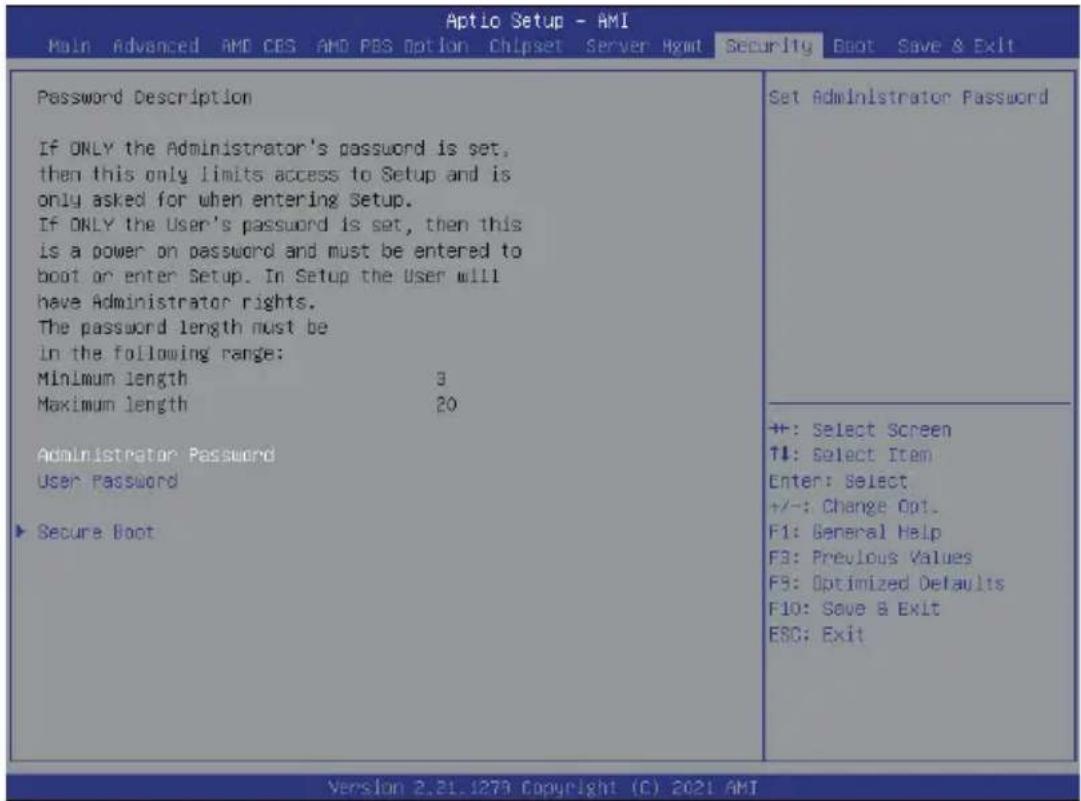
There are two types of passwords that you can set:
- Administrator Password Entering this password will allow the user to access and change all settings in the Setup Utility.
- User Password Entering this password will restrict a user's access to the Setup menus. To enable or disable this field, a Administrator Password must first be set. A user can only access and modify the System Time, System Date, and Set User Password fields.
| Parameter | Description |
| Administrator Password | Press [Enter] to configure the administrator password. |
| User Password | Press [Enter] to configure the user password. |
| Secure Boot | Press [Enter] to configure advanced items. |
5-7-1 Secure Boot
The Secure Boot submenu is applicable when your device is installed the Windows® 8 (or above) operating system.
| System Mode | Setup | Secure Boot feature is Active if Secure Boot is Enabled, Platform Key(PK) is enrolled and the System is in User mode. The mode change requires platform reset |
| Secure Boot | [Disabled] Not Active | |
| Secure Boot Mode | [Custom] | |
| Restore Factory Keys | ||
| Reset To Setup Mode | ||
| Enter Audit Mode | ||
| Key Management | ||
| +: Select Screen ↑↓: Select Item Enter: Select +/-: Change Opt. F1: General Help F3: Previous Values F9: Optimized Defaults F10: Save & Exit ESC: Exit |
| Parameter | Description |
| System Mode | Displays if the system is in User mode or Setup mode. |
| Secure Boot | Enable/ Disable the Secure Boot function.Options available:Enabled/Disabled. Default setting is Disabled. |
| Secure Boot Mode(Note) | Secure Boot requires all the applications that are running during the booting process to be pre-signed with valid digital certificates. This way, the system knows all files being loaded before Windows loads to the login screen have not been tampered with.When set to Standard, it will automatically load the Secure Boot keys form the BIOS databases.When set to Custom, you can customize the Secure Boot settings and manually load its keys from the BIOS database.Options available: Standard/Custom. Default setting is Standard. |
| Restore Factory Keys | Forces the system to user mode and installs factury default Secure Boot key database. |
| Reset to Mode(Note) | |
| Enter Audit Mode | Enter Audit Mode workflow. Transitions from User to Audit. Mode will result in erasing of PK variable. |
(Note) Advanced items prompt when this item is set to Custom.
| Parameter | Description |
| Key Management | Press [Enter] to configure advanced items.Please note that this item is configurable when Secure Boot Mode is set to Custom.◆ Factory Key Provision- Allows to provision factory default Secure Boot keys when system is in Setup Mode.- Options available: Enabled/Disabled. Default setting is Disabled.◆ Restore Factory Keys- Installs all factory default keys. It will force the system in User Mode.- Options available: Yes/No.◆ Enroll Efi Image- Press [Enter] to enroll SHA256 hash of the binary into Authorized Signature Database (db).◆ Restore DB defaults- Restore DB variable to factory defaults.◆ Secure Boot variable- Displays the current status of the variables used for secure boot.◆ Platform Key (PK)- Displays the current status of the Platform Key (PK).- Press [Enter] to configure a new PK.- Options available: Set New.◆ Key Exchange Keys (KEK)- Displays the current status of the Key Exchange Key Database (KEK).- Press [Enter] to configure a new KEK or load additional KEK from storage devices.- Options available: Set New/Append.◆ Authorized Signatures (DB)- Displays the current status of the Authorized Signature Database.- Press [Enter] to configure a new DB or load additional DB from storage devices.- Options available: Set New/Append.◆ Forbidden Signatures (DBX)- Displays the current status of the Forbidden Signature Database.- Press [Enter] to configure a new dbx or load additional dbx from storage devices.- Options available: Set New/Append.◆ Authorized TimeStamps (DBT)- Displays the current status of the Authorized TimeStamps Database.- Press [Enter] to configure a new DBT or load additional DBT from storage devices.- Options available: Set New/Append.◆ OsRecovery Signatures- Displays the current status of the OsRecovery Signature Database.- Press [Enter] to configure a new OsRecovery Signature or load additional OsRecovery Signature from storage devices.- Options available: Set New/Append. |
5-8 Boot Menu
The Boot menu allows you to set the drive priority during system boot-up. BIOS setup will display an error message if the legacy drive(s) specified is not bootable.
![Aptio Setup - AMI Main Advanced AMD CBS AMD PBS Option Chipset Server Hgmt Security Boot Save & Exit Boot Configuration Setup Prompt Timeout 2 Bootup NumLock State [On] Quiet Boot [Enabled] Boot mode select [UEFI] FIXED BOOT ORDER Priorities Boot Option #1 [Hard Disk] Boot Option #2 [CD/DVD] Boot Option #3 [USB Device] Boot Option #4 [Network:UEFI: PXE IFv4 Intel(R) Network 18:CO:4D:OS:3B:C7] Boot Option #5 [UEFI AP:UEFI: Built-in EFI Shell] ▶ UEFI NETWORK Drive DOS Priorities ▶ UEFI Application Boot Priorities Number of seconds to wait for setup activation key. 6S59S(0xFFFF) means indefinite waiting. +: Select Screen T4: Select Item Enter: Select +/-: Change Opt. F1: General Help F3: Previous Values F9: Optimized Defaults F10: Save & Exit ESC: Exit Version 2.21.1279 Copyright (C) 2021 AMI](/content/2026/05/1109911/images/5efc9601a7ac1dd18f4a8becfbf2b71be2fd21eead8ed34203b06e35a768520b.jpg)
| Parameter | Description |
| Boot Configuration | |
| Setup Prompt Timeout | Number of seconds to wait for setup activation key. 65535 (0xFFFF) means indefinite waiting.Press the numeric keys to input the desired values. |
| Bootup NumLock State | Enable/Disable the Bootup NumLock function.Options available: On/Off. Default setting is Off. |
| Quiet Boot | Enable/Disable showing the logo during POST.Options available: Enabled/Disabled. Default setting is Enabled. |
| Boot mode select | Selects the boot mode.Options available: LEGACY/UEFI. Default setting is UEFI. |
| FIXED BOOT ORDER Priorities | |
| Boot Option #1 / #2 / #3 / #4 / #5 | Press [Enter] to configure the boot priority.By default, the server searches for boot devices in the following sequence:1. Hard drive.2. CD-COM/DVD drive.3. USB device.4. Network.5. UEFI. |
| UEFI Network Drive BBS Priorities | Press [Enter] to configure the boot priority. |
| UEFI Application Boot Priorities | Press [Enter] to configure the boot priority. |
5-8-1 UEFI NETWORK Drive BBS Priorities
The UEFI network drive BBS priorities submenu allows you to specify the boot device priority from the available UEFI network drives during system boot-up. BIOS setup will display an error message if the legacy drive(s) specified is not bootable.
![Optio Setup Utility - Copyright (C) 2020 American Megatrends, Inc. Boot Boot Option #1 [UEFI: PXE IP4 Intel(R) I350 Gigabit Network Connection] Boot Option #2 [UEFI: PXE IP4 Intel(R) I350 Gigabit Network Connection] Boot Option #3 [UEFI: PXE IP6 Intel(R) I350 Gigabit Network Connection] Boot Option #4 [UEFI: PXE IP6 Intel(R) I350 Gigabit Network Connection] Sets the system boot order +: Select Screen ↑↓: Select Item Enter: Select +/-: Change Opt. F1: General Help F3: Previous Values F9: Optimized Defaults F10: Save & Exit ESC: Exit Version 2.20.1275. Copyright (C) 2020 American Megatrends, Inc.](/content/2026/05/1109911/images/9989cfcf7a40b1137eeae8e3bb86f558178cafcaab0545b54d9e41b3585c3ffc.jpg)
5-8-2 UEFI Application Boot Priorities
The UEFI application boot priorities submenu allows you to specify the boot device priority from the available UEFI applications during system boot-up. BIOS setup will display an error message if the legacy drive(s) specified is not bootable.
![Aptio Setup Utility - Copyright (C) 2020 American Megatrends, Inc. Boot Boot Option #1 [UEFI: Built-in EPI Shell] sets the system boot order +: Select Screen +: Select Item Enter: Select +/-: Change Opt. F1: General Help F3: Previous Values F9: Optimized Defaults F10: Save & Exit ESC: Exit Version 8.20.1275. Copyright (C) 2020 American Megatrends, Inc.](/content/2026/05/1109911/images/10022614ceb9382fe318b343013fbfb558caddb7a68606494997d368d32af266.jpg)
5-9 Save & Exit Menu
The Save & Exit menu displays the various options to quit from the BIOS setup. Highlight any of the exit options then press

| Parameter | Description |
| Save Options | |
| Save Changes and Exit | Saves changes made and closes the BIOS setup. Options available: Yes/No. |
| Discard Changes and Exit | Discards changes made and exits the BIOS setup. Options available: Yes/No. |
| Save Changes | Saves changes done so far to any of the setup options. Options available: Yes/No. |
| Default Options | |
| Restore Defaults | Loads the default settings for all BIOS setup parameters. Setup Defaults are quite demanding in terms of resources consumption. If you are using low-speed memory chips or other kinds of low-performance components and you choose to load these settings, the system might not function properly. Options available: Yes/No. |
| Boot Override | Press [Enter] to configure the device as the boot-up drive. |
| Launch EFI Shell from filesystem device | Attempts to Launch EFI Shell application (Shell.efi) from one of the available filesystem devices. |
5-10 BIOS POST Beep code (AMI standard)
5-10-1 PEI Beep Codes
| # of Beeps Description |
| 1 Memory not Installed. |
| 1 Memory was installed twice (InstallPeiMemory routine in PEI Core called twice) |
| 2 Recovery started |
| 3 DXEIPL was not found |
| 3 DXE Core Firmware Volume was not found |
| 4 Recovery failed |
| 4 S3 Resume failed |
| 7 Reset PPI is not available |
5-10-2 DXE Beep Codes
| # of Beeps Description | |
| 1 Invalid password | |
| 4 Some of the Architectural Protocols are not available | |
| 5 No Console Output Devices are found | |
| 5 No Console Input Devices are found | |
| 6 Flash update is failed | |
| 7 Reset protocol is not available | |
| 8 Platform PCI resource requirements cannot be met | |
This page intentionally left blank
- Disclaimer
- Documentation Classifications
- For More Information
- Conventions
- Server Warnings and Cautions
- WARNING!
- To reduce the risk of electric shock or damage to the equipment:
- CAUTION!
- Electrostatic Discharge (ESD)
- Table of Contents
- Chapter 1 Hardware Installation ...... 11
- Chapter 2 System Appearance....17
- Chapter 3 System Hardware Installation ....25
- Chapter 4 Motherboard Components ....57
- Chapter 5 BIOS Setup ....59
- 5-3 AMD CBS Menu....92
- 5-4 AMD PBS Menu 130
- 5-5 Chipset Setup Menu....133
- 5-6 Server Management Menu....136
- 5-7 Security Menu 142
- 5-8 Boot Menu....145
- 5-9 Save & Exit Menu.... 149
- 5-10 BIOS POST Beep code (AMI standard).... 150
- Chapter 1 Hardware Installation
- 1-1 Installation Precautions
- 1-2 Product Specifications
- NOTE:
- Socket Per Node:
- Total:
- Memory Per Node:
- LAN Per Node:
- Per Node:
- Internal I/O Per Node:
- Front I/O Per node:
- Rear I/O Per node:
- 1-3 System Block Diagram
- Chapter 2 System Appearance
- 2-1 Front View
- No. Decription
- 2-2 Rear View
- 2-3 Front Panel LED and Buttons
- 2-4 RoT LEDs
- NOTE!
- 2-5 Rear System LAN LEDs
- 2-6 Power Supply Unit LED
- 2-7 Hard Disk Drive LEDs
- Chapter 3 System Hardware Installation
- 3-1 Installing the Hard Disk Drive
- 3-2 Removing the Node
- 3-3 Removing Chassis Cover
- Follow these instructions to remove the system cover:
- 3-4 Removing and Installing the Fan Duct
- 3-5 Removing and Installing the Heatsink
- 3-6 Installing the CPU
- 3-7 Installing Memory
- 3-7-1 Eight Channel Memory Configuration
- 3-7-2 Installing the Memory
- Follow these instructions to install the Memory:
- 3-7-3 Processor and Memory Module Matrix Table
- 3-7-4 Memory Population Table
- 3-8 Installing the PCI Expansion Card
- Follow these instructions to install the right PCI Expansion card:
- Follow these instructions to install the left PCI Expansion card:
- 3-9 Installing the Mezzanine Card
- 3-9-1 Installing the OCP 3.0 Mezzanine Card
- Follow these instructions to install an OCP 3.0 Mezzanine card:
- 3-10 Replacing the Fan Assembly
- 3-11 Replacing the Power Supply
- 3-12 Replacing Power Distribution Board Cage
- 3-13 Cable Routing
- Power Distribution Board to Middle Board Cable (Top)
- Power Distribution Board to Middle Board Cable (Bottom)
- Top Middle Board to HDD Back Plane Board Cable (SATA1)
- Top Middle Board to HDD Back Plane Board Cable (SATA3)
- Bottom Middle Board to HDD Back Plane Board Cable (SATA4)
- Top Middle Board to HDD Back Plane Board Cable (NVMe/Node1)
- Top Middle Board to HDD Back Plane Board Cable (NVMe/Node3)
- Bottom Middle Board to HDD Back Plane Board Cable (NVMe/Node4)
- LAN Bridge Cable
- On-Board SATA to HDD Back Plane Board Cable
- 3-13-2 H262-Z6B
- Front Switch Cable/Front LED Cable
- Bottom Middle Board to HDD Back Plane Board Cable (NVMe/Node2)
- Chapter 4 Motherboard Components
- 4-1 Motherboard Components
- Item Description
- 4-2 Jumper Setting
- Chapter 5 BIOS Setup
- Main
- ■ Advanced
- AMD CBS
- AMD PBS Option
- Chipset
- ■ Server Management
- ■ Security
- Boot
- ■ Save & Exit
- 5-1 The Main Menu
- Main Menu Help
- Submenu Help
- 5-2 Advanced Menu
- When "Boot Mode Select" is set to Legacy in the Boot > Boot Mode Select section
- 5-2-1 Trusted Computing
- 5-2-2 PSP Firmware Versions
- 5-2-3 Legacy Video Select
- 5-2-4 AST2500 Super IO Configuration
- 5-2-4-1 Serial Port 1 Configuration
- 5-2-5 S5 RTC Wake Settings
- 5-2-6 Serial Port Console Redirection
- 5-2-7 CPU Configuration
- 5-2-8 PCI Subsystem Settings
- 5-2-9 USB Configuration
- 5-2-10 Network Stack Configuration
- 5-2-11 NVMe Configuration
- 5-2-12 SATA Configuration
- 5-2-14 AMD Mem Configuration Status
- 5-2-15 TIs Auth Configuration
- 5-2-16 Intel(R) Ethernet Controller I350
- 5-2-17 VLAN Configuration
- 5-2-19 MAC IPv6 Network Configuration
- 5-3 AMD CBS Menu
- 5-3-1 CPU Common Options
- 5-3-1-1 Performance
- 5-3-1-2 Prefetcher Settings
- 5-3-1-3 Core Watchdog
- 5-3-2 DF Common Options
- 5-3-2-1 Scrubber
- 5-3-2-2 Memory Addressing
- 5-3-2-3 ACPI
- 5-3-3 UMC Common Options
- Parameter Description
- 5-3-3-1 DDR4 Common Options
- 5-3-3-1-2 CAD Bus Configuration
- 5-3-3-1-3 Data Bus Configuration
- 5-3-3-1-4 Common RAS
- 5-3-3-2 DRAM Memory Mapping
- 5-3-3-4 Memory MBIST
- 5-3-3-4-1 Data Eye
- 5-3-4 NBIO Common Options
- 5-3-4-1 SMU Common Options
- 5-3-4-2 NBIO RAS Common Options
- 5-3-5 FCH Common Options
- 5-3-5-1 AC Power Loss Options
- 5-3-5-3 Miscellaneous Options
- 5-3-6 NTB Common Options
- 5-3-7 SOC Miscellaneous Control
- 5-3-8 Workload Tuning
- 5-4 AMD PBS Menu
- 5-5 Chipset Setup Menu
- 5-5-1 North Bridge
- 5-5-2 Fabric Resource
- 5-6 Server Management Menu
- 5-6-1 System Event Log
- 5-6-2 View FRU Information
- 5-6-3 BMC Network Configuration
- 5-6-4 IPv6 BMC Network Configuration
- 5-7 Security Menu
- 5-7-1 Secure Boot
- 5-8 Boot Menu
- 5-8-1 UEFI NETWORK Drive BBS Priorities
- 5-8-2 UEFI Application Boot Priorities
- 5-9 Save & Exit Menu
- 5-10 BIOS POST Beep code (AMI standard)
- 5-10-1 PEI Beep Codes
- 5-10-2 DXE Beep Codes
Brand : GIGABYTE
Model : H262-Z6B
Category : Uncategorized