
AT-HD4-V40SRS - AV Connector Atlona - Free user manual and instructions
Find the device manual for free AT-HD4-V40SRS Atlona in PDF.


| Product Type | HDMI Extender with Bi-Directional IR |
| Brand | Atlona |
| Model | AT-HD4-V40SRS |
| Transmission Technology | HDMI over CAT5/5e/6/7 |
| Maximum Transmission Distance (1080p) | 130 ft (40m) CAT5e, 165 ft (50m) CAT6 |
| Maximum Transmission Distance (1080i/720p) | 200 ft (60m) CAT6 |
| Video Support | 480i/p, 720p, 1080i, 1080p (30/50/60) |
| Audio Support | Surround sound up to 7.1ch, Dolby TrueHD, DTS-HD |
| 3D Support | Yes (all 7 formats) |
| HDCP Compliance | HDCP 2.0 |
| Deep Color | Yes |
| IR Pass-through | Bi-directional (20-60kHz) |
| Equalization | 8-step digital control on receiver |
| EDID Modes | 7 embedded + learning |
| Inputs (TX) | 1x HDMI, 1x 3.5mm IR receiver, 1x 3.5mm IR blaster, 1x RJ45 out |
| Outputs (RX) | 1x HDMI, 1x 3.5mm IR receiver, 1x 3.5mm IR blaster, 1x RJ45 in |
| Power Supply | 5V 2A DC (included, two units) |
| Power Consumption | 1.5W |
| Dimensions (each module) | 2.9 x 3.5 x 1 in (75 x 90 x 25 mm) |
| Weight (each module) | 1.1 lbs (480g) |
| Housing | Metal enclosure |
| Mounting | Wall-mountable with screws |
| Operating Temperature | 32~104°F (0~40°C) |
| Storage Temperature | -4~140°F (-20~60°C) |
| Relative Humidity | 20~90% RH (no condensation) |
| Warranty | 3 years limited |
| Maintenance | Clean with a damp cloth; avoid cleaning fluids or aerosols. |
| Safety | Operate only with included power supply; do not expose to rain or moisture. |
| Spare Parts/Accessories | IR blaster and receiver cables can be purchased separately (compatible with 3.5mm jack). |
Frequently Asked Questions - AT-HD4-V40SRS Atlona
User questions about AT-HD4-V40SRS Atlona
0 question about this device. Answer the ones you know or ask your own.
Ask a new question about this device
Download the instructions for your AV Connector in PDF format for free! Find your manual AT-HD4-V40SRS - Atlona and take your electronic device back in hand. On this page are published all the documents necessary for the use of your device. AT-HD4-V40SRS by Atlona.
USER MANUAL AT-HD4-V40SRS Atlona
TABLE OF CONTENTS
- Introduction 3
- Package Contents 3
- Features 3
- Specification 4
- Panel Descriptions 5
5.1. Transmitting Module 5
5.1.1. Front Panel 5
5.1.2. Rear Panel 5
5.2. Receiving Module 6
5.2.1. Front Panel 6
5.2.2. Rear Panel 6
6. IR Pass-through 7
6.1. IR Extenders 7
6.2. IR Sockets 7
6.3. Definition of IR Earphone Jack 7
6.4. Supported IR Data Format 8
7. Installation 8
8. EDID Learning 8
9. Pin Definition 9
9.1.HDMI TM 9
9.2. CAT5 [RJ45] 9
- Connection Diagram 10
- Performance Guide 10
- Notice 11
- Safety Information 12
- Warranty 13
- Atlona Product Registration 14
INTRODUCTION:
The Atlona AT-HD4-V40SRS is an HDMI with Bi-Directional IR Extension Kit. The extenders are designed to handle full 1080p up to 130ft and 1080i/720p up to 200ft. The HD4-V40SRS are capable of supporting very high bandwidth and there are able to handle all 7 x 3D formats.
The Atlona HD4-V40SRS are based on the latest HDMI technology and therefore are capable of fully supporting HDCP 2.0, Deep Color and DTS-HD or Dolby TrueHD audio. In addition, AT-HD4-V40SRS are also equipped with bi-directional IR pass-through, which allows users to control the sources from the remote location as well as sending IR signal from a control system to a remote location. Perfect for Control4, RTI, HAI or any other control system users or dealers.
The AT-HD4-V40SRS includes two modules: transmitting module and receiving module, where the transmitter module converts HDMI with IR to RJ45 and the receiver module converts it back to HDMI and IR. The receiver module is featured with 8-step equalization control, to allow users to adjust the equalization strength to the received HDMI signals accordingly, and therefore optimize the transmission distance between source and display.
PACKAGE CONTENTS:
• 1x AT-HD4-V40SRS (Transmitting and Receiving Modules)
- 1x IR blaster
- 1x IR receiver
- 2x 5V power supply unit
- 1x User's manual
FEATURES:
- Extends the transmission range up to 130ft (40m) at full 1080p or 1920x1200 or 200ft (60M) at 1080i/720p
• Supports all latest Audio formats such as Dolby True HD, DTS-master, etc... - 3D Compatible (all 7 formats), including the most popular e.g., Frame Packing, Side-by-Side, Top-to-Bottom, etc...
- 7 x Embedded EDID functions and Learning EDID function available. Learning function allows user to trick the source to think that it connected to the display rather than going though extenders. This advantage can fix a lot of EDID issues which may happen in a complicated installations with different components involved.
• Supports Bi-Directional IR pass-through up to 60Khz, allows users not only send IR signals from remote location but also to remote location from a control system. Great for Control4 or RTI installers.
• Supports VESA DDC and Hot-Plug Detect (HPD) - HDCP compatible
• DVI 1.0 compliant, user will need to use DVI/HDMI adapter
• Supports Deep Color - Allows cascading
• Wall mounting housing design for easy and robust installation - Locking Power connector
* The claimed transmission distance is subject to the grade of installed cable(s), source devices and displays.
* For Cat.X transmission, the cable(s) should be solid, not stranded. Any keystone jack along the transmission path will lower the transmission performance significantly!
SPECIFICATIONS:
| Technical Transmitter Receiver | |||
| Role of usage Transmitter [TX] Receiver [RX] | |||
| HDCP compliance Yes | |||
| Video bandwidth Single-link 6.75Gbps [225MHz] | |||
| Video support 480i/p / 720p (50/60) / 1080i (50/60) / 1080p (30/50/60) | |||
| HDMI over UTP transmission | Full HD (1080p)-130ft (40m) [CAT5e] / 165ft (50m) [CAT6] HD (720p/1080i)-165ft (50m) [CAT5e] / 200ft (60m) [CAT6] | ||
| Audio support Surround sound (up to 7.1ch) or stereo digital audio | |||
| Signal Equalization 8-level digital control at RX | |||
| Input TMDS signal 1.2 Volts [peak-to-peak] | |||
| Input DDC signal 5 Volts [peak-to-peak, TTL] | |||
| ESD protection | [1] Human body model — ±19kV [air-gap discharge] & ±12kV [contact discharge][2] Core chipset — ±8kV | ||
| PCB stack-up 4-layer board [impedance control — differential 100Ω; single 50Ω] | |||
| IR pass-thru Bi-directional | |||
| Input | 1x HDMI; 1x 3.5mm | 1x RJ45; 1x 3.5mm | |
| Output | 1x RJ45; 1x 3.5mm | 1x HDMITM; 1x 3.5mm | |
| HDMI TM source control | Controllable via IR pass-through from RX to TX with IR extenders | ||
| IR remote control | Electro-optical characteristics: τ = 25° / Carrier frequency: 20-60kHz | ||
| HDMI TM connector | Type A [19-pin female] | ||
| RJ45 connector | WE/SS 8P8C with 2 LED indicators | ||
| 3.5mm connector | IR receiver | IR blaster | |
| Rotary control switch | EDID Mode | Signal level | |
| Mechanical | |||
| Housing | Metal enclosure | ||
| Dimensions[L x W x H] | Model | 2.9" x 3.5" x 1" (75 x 90 x 25mm) | |
| Package 6.9" x 10.6" x 3.1" (175 x 270 x 80mm) | |||
| Carton | 1'3" x 1'6" x 1' (370 x 450 x 300mm) | ||
| Weight | Model | 1.1 lbs (480g) | |
| Package | 1.7 lbs (780g) | ||
| Fixedness | Wall-mounting case with screws | ||
| Power supply | 5V 2A DC | ||
| Power consumption | 1.5 W | ||
| Operation temperature | 32~104°F (0~40°C) | ||
| Storage temperature | -4~140°F (-20~60°C) | ||
| Relative humidity 20~90% RH (no condensation) | |||
PANEL DESCRIPTIONS:
5.1. Transmitting Module
5.1.1. Front Panel

- MODE: 0 - EDID Full-HD (up to 1080p@60) -24bit 2D video & 7.1ch audio – long distance
1 - EDID Full-HD (up to 1080p@60) – 24-bit 2D video & 2ch audio – long distance
2 - EDID Full-HD (1080p@60) - 36bit 2D video & 7.1ch audio
3 - EDID Full-HD (1080p@60) - 36bit 2D video & 2ch audio
4 - EDID Full-HD (1080p@60) - 36bit 3D video & 7.1ch audio
5 - EDID HD (1080p@30)(1080i@50/60)(720p@50/60) - 24bit 2D video & 2ch audio
6 - EDID Full-HD (1080p@60) - 36bit 3D video & 2ch audio
7 - EDID learning mode
2. HDMI IN: Connects to a HDMI source with a HDMI male-male cable
3. IR Receiver: Infrared 3.5mm socket for plugging in the extension cable of IR receiver
4. IR Blaster: Infrared 3.5mm socket for plugging in the extension cable of IR blaster
5.1.2. Rear Panel

- +5V DC: Connect to 5V DC power supply.
- CAT5/6/7 OUT: Plug in a Cat-5/5e/6/7 cable that needs to be linked to the Transmitting module.
5.2. Receiving Module
5.2.1. Front Panel

-
EQ: Adjust the 8-level equalization control to the received HDMI™ signals. The HDMI™ signal level varies from MAX (strongest) to MIN (weakest) for respective transmission length from longest possible range to short distance. Please adjust the signal level from MIN to MAX and stop turning the rotary switch whenever the audio/video is playing normally.
-
HDMI OUT: Connect to HDMI display with a HDMI male-male cable.
-
IR Receiver: Infrared 3.5mm socket for plugging in the extension cable of IR receiver
-
IR Blaster: Infrared 3.5mm socket for plugging in the extension cable of IR blaster
5.2.2. Rear Panel

- +5V DC: Connect to 5V DC power supply.
- CAT5/6/7 IN: Plug in a Cat-5/5e/6/7 cable that needs to be linked to the Receiving module.
IR PASS-THROUGH
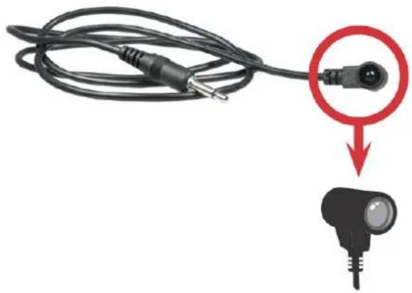
6.1. IR Extenders.
IR Blaster
natural_image
Close-up of a black cable with a red circle highlighting a connector, and a separate black connector with a light bulb below (no text or symbols)IR Receiver

natural_image
Close-up of a black cable with two connectors, one highlighted by a red circle (no text or symbols)6.2. IR Sockets.
IR BLASTER: plug in the IR blaster to emit all IR command signals received from the IR receiver from the other end to control the devices corresponding to the IR signals.
IR RECEIVER: plug in the IR receiver to receive all IR command signals from the IR remote controls of the corresponding devices.
Note: IR Blaster is designed to be attached to the Source device
Note: IR Receiver is designed to be placed somewhere in the remote location where an IR Remote could be pointed to it.
CAUTION!
Incorrect placement of IR Blaster and Receiver may result in the failure of the IR extenders. Please check carefully before plugging in the IR extender to the respective IR sockets. Warranty will not cover the damage.
6.3. Definition of IR Earphone Jack.
IR Blaster

* User can purchase any IR extension cables in the market that are compatible to the definition of the IR sockets. However, IR cables longer than 2m (6-ft) may not work.
6.4. Supported IR Data Format.
| Data Format Suitable Not Recommended | |
| NEC v | |
| RC5 v | |
| TOSHIBA MICOM CODE v | |
| GRUNDIG CODE v | |
| SONY 12 BIT CODE v | |
| SONY 15 BIT CODE v | |
| SONY 20 BIT CODE v | |
| RCA CODE v | |
| RCM CODE v | |
| MATSUSHITA CODE v | |
| MITSUBISHI CODE v | |
| ZENITH CODE v | |
| JVC CODE v | |
| M50560-001P v | |
| MN6125H | v |
| MN6125L | v |
| MN6014_C5D7 | v |
| MN6014_C6D6 | v |
| MC14457P | v |
| LC7464(AHEA) | v |
| GEMINI_CM | v |
INSTALLATION
-
Connect a HDMI or DVI source (such as a Blu-ray Disc player) to the transmitting module of AT-HD4-V40SRS.
-
Connect a HDMITM or DVI display (such as a LCD TV) to the receiving module of AT-HD4-V40SRS.
-
Connect IR Blaster/Receiver to both TX and RX modules.
-
Connect a Cat-5/5e/6/7 cable between the transmitting and receiving modules.
-
Make sure this Cat-5/5e/6/7 cable is tightly connected and not loose.
-
Plug in 5V DC power supply unit to the power jack of the receiving module of AT-HD4-V40SRS.
-
Plug in 5V DC power supply unit to the power jack of the transmitting module of AT-HD4-V40SRS.
-
If you see flickering or blinking image on the display, please adjust the rotary control switch to improve the cable skew. MAX stands for the strongest HDMITM signal level for longest possible transmission length while MIN stands for the weakest HDMITM signal level for short transmission length. Please adjust the signal level from MIN to MAX and stop turning the rotary switch whenever the audio/video is playing normally.
EDID LEARNING
-
Turn off TX module and disconnect the Cat.5/5e/6/7 cable between TX and RX modules.
-
Connect the HDMI display to "HDMI IN" on the TX module with a HDMITM cable.
-
Set "MODE" on the transmitting module of AT-HD4-V40SRS at 7.
-
Connect the TX module to the power supply.
-
The LED on the RJ45 of the transmitting module will dim and light again, which indicates the EDID learning procedure is complete.
-
Unplug the HDMI cable from the display and turn the "MODE" selection Clockwise to # 1 or # 0, depending on whether the Stereo or Multi-Channel Audio is being transmitted.
Important Note: If user wants to erase learned EDID and set the transmitter's EDID setting to default, please dial the "MODE" Clockwise or Counter-Clockwise and pass #5
PIN DEFINITION
9.1. HDMI TM

Type A (Receptacle) HDMI™
| Pin 1 TMDS Data2+ Pin 8 TMDS Data0 Shield Pin 15 SCL |
| Pin 2 TMDS Data2 Shield Pin 9 TMDS Data0- Pin 16 SDA |
| Pin 3 TMDS Data2- Pin 10 TMDS Clock+ Pin 17 DDC/CEC Ground |
| Pin 4 TMDS Data1+ Pin 11 TMDS Clock Shield Pin 18 +5 V Power |
| Pin 5 TMDS Data1 Shield Pin 12 TMDS Clock- Pin 19 Hot Plug Detect |
| Pin 6 TMDS Data1- Pin 13 CEC |
| Pin 7 TMDS Data0+ Pin 14 Reserved (N.C. on device) |
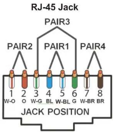
9.2. CAT5 [RJ45]
| Data Link TIA/EIA-568-B | |||
| PIN Color | Function | ||
| 1 |  | W-O | TX0- |
| 2 |  | O | TX0+ |
| 3 |  | G-O | TX1- |
| 4 |  | BL | TX2- |
| 5 |  | W-BL | TX2+ |
| 6 |  | G | TX1+ |
| 7 |  | W-BR | TXC- |
| 8 |  | BR | TXC+ |
CONNECTION DIAGRAM

PERFORMANCE GUIDE
| Performance rating Type of category cable | ||||
| Wiring Shielding CAT5 CAT5e CAT6 | ||||
| Solid Unshielded (UTP) *** **** ***** | ||||
| Shielded (STP) *** *** **** | ||||
| Stranded Unshielded (UTP) * | ** | ** | ||
| Shielded (STP) | ** | ** | ||
| Termination | Please use EIA/TIA-568-B termination (T568B) at any time | |||
NOTICE
- When adjusting the signal level on the receiver module, please dial the rotary control switch from MIN to MAX and stop turning the rotary switch whenever the audio/video is playing normally. Inappropriate signal level setting may cause overpowering issue that would shorten the product life significantly!
- Wrongly insert IR blaster and IR receiver to wrong 3.5mm infrared sockets may result in the failure of the IR extenders. Please check carefully before plugging in the IR extender to the respective IR sockets.
- If the DVI or HDMI TM device requires the EDID information, please use EDID Reader/Writer to retrieve and provide DVI or HDMI TM display EDID information.
- All HDMI ™ over CAT5 transmission distances are measured using Belden 1583A CAT5e 125MHz UTP cable and ASTRODESIGN Video Signal Generator VG-859C & VG-870B.
- The transmission length is largely affected by the type of Cat-5/5e/6 cables, the type of HDMI ™ sources, and the type of HDMI ™ display. The testing result shows solid UTP cables (usually in the form of 300m [1,000ft] bulk cables) can transmit a lot longer signals than stranded UTP cables (usually in the form of fixed length patch cords). Shielded STP cables are better suited than unshielded UTP cables. A solid UTP Cat-5e cable shows longer transmission range than stranded STP Cat-6 cable. For long extension applications, solid UTP/STP cables are the only viable choice.
- EIA/TIA-568-B termination (T568B) for Cat-5/5e/6 cables is recommended for better performance.
- To reduce the interference among the unshielded twisted pairs of wires in Cat-5/5e/6 cable, one can use shielded STP cables to improve EMI problems, which is worsen in long transmission.
- Because the quality of the CAT5/6 cables has the major effect on how long the transmission limit can achieve and how good is the received picture quality, the actual transmission range is subject to one's choice of Cat-5/5e/6 cables. For desired resolutions greater than 1080i or 1280x1024, a Cat-6 cable is recommended.
- If your HDMI™ display has multiple HDMI™ inputs, it is found that the first HDMI™ input [HDMI™ input #1] generally can produce better transmission performance among all HDMI™ inputs.
Possible Issues and Solutions:
- No Audio/video Signal on the Display or Signal is going in and Out:
a. Please test your RJ45 cables with a Fluke or similar tester to make sure that all the wires are connected and the distance is within the limits.
b. If you are using patch panel or and RJ45 wall plates, the distance will be reduced, please do a direct connecting bypassing all additional equipment.
c. Please try to re-terminate your CAT5/6/7 wire to 568B
d. Please try adjusting EQ gain on the receiver unit
e. Please try changing a mode on the transmitter to #0 or to #1 (depending on the audio format required f. Please go into the menu of the source device and select 720p/1080i or 1080p resolution instead of AUTO
q. If the sync device is a projector or AVR, please try learning EDID, instructions are on the previous page
- When connected between 3D player and 3D display, only able to see 2D image:
a. Please try changing "MODE" on the transmitter module to 4 or 6
b. Please go into the menu of the source device and enable 3D
- Signal is Going In and Out when going into the AVR: however works well connected directly to the TV
a. Please try Learning EDID of the AVR while the AVR HDMI out is connected to the display (both AVR and Display should be ON)
b. Select "MODE" on the transmitter to # 0, #2 or #4
SAFETY INFORMATION:
Safeguards
To reduce the risk of electric shock, do not expose this product to rain or moisture.
If the wall plug does not fit into your local power socket, hire an electrician to replace your obsolete socket.
Do not modify the wall plug. Doing so will void the warranty and safety features.
This equipment should be installed near the socket outlet and the device should be easily accessible in case it requires disconnection.
Precautions
FCC Regulations state that any unauthorized changes or modifications to this equipment not expressly approved by the manufacturer could void the user's authority to operate this equipment.
Operate this product using only the included external power supply. Use of other power supplies could impair performance, damage the product or cause fires.
In the event of an electrostatic discharge, this device may automatically turn off. If this occurs, unplug the device, and plug it back in.
Protect and route power cords so they will not be stepped on or pinched by anything placed on or against them. Be especially careful of plug-ins, or cord exit points from this product.
Avoid excessive humidity, sudden temperature changes or temperature extremes.
Keep this product away from wet locations such as bathtubs, sinks, laundries, wet basements and swimming pools.
Use only accessories recommended by ATLONA to avoid fire, shock or other hazards.
Unplug the product before cleaning. Use a damp cloth for cleaning. Do not use cleaning fluid or aerosols, which could enter the unit and cause damage, fire or electrical shock. Some substances may also mar the finish of the product.
Never open or remove unit panels or make any adjustments not described in this manual. Attempting to do so could expose you to dangerous electrical shock or other hazards. It may also cause damage to your AT-HD4-V40SRS. Opening the product will void the warranty.
Do not attempt to service the unit. Instead disconnect it and contact your Authorized ATLONA reseller or contact ATLONA directly.
WARRANTY
1. LIMITED WARRANTY
Atlona Technologies warrants that (a) its products (the "Product") will perform substantially in accordance with the accompanying written materials for a period of 3 YEARS from the date of receipt and (b) that the Product will be free from defects in materials and workmanship under normal use and service for a period of 3 years. In the event applicable law imposes any implied warranties, the implied warranty period is limited to 3 years from the date of receipt. Some jurisdictions do not allow such limitations on duration of an implied warranty, so the above limitation may not apply to Customer.
2. CUSTOMER REMEDIES
Atlona Technologies and its suppliers' entire liability and Customer's exclusive remedy shall be, at Atlona Technologies' option, either return of the price paid for the Product, or repair or replacement of the Product that does not meet this Limited Warranty and which is returned to Atlona Technologies with a copy of Customer's receipt. This Limited Warranty is void if failure of the Product has resulted from accident, abuse, or misapplication. Any replacement Product will be warranted for the remainder of the original warranty period or 3 year, whichever is longer.
3. NO OTHER WARRANTIES
TO THE MAXIMUM EXTENT PERMITTED BY APPLICABLE LAW, ATLONA TECHNOLOGIES AND ITS SUPPLIERS DISCLAIM ALL OTHER WARRANTIES, EITHER EXPRESS OR IMPLIED, INCLUDING, BUT NOT LIMITED TO IMPLIED WARRANTIES OF MERCHANTABILITY AND FITNESS FOR A PARTICULAR PURPOSE, WITH REGARD TO THE PRODUCT AND ANY RELATED WRITTEN MATERIALS. THIS LIMITED WARRANTY GIVES CUSTOMER SPECIFIC LEGAL RIGHTS. CUSTOMER MAY HAVE OTHER RIGHTS DEPENDING ON THE JURISDICTION.
4. NO LIABILITY FOR DAMAGES
TO THE MAXIMUM EXTENT PERMITTED BY APPLICABLE LAW, IN NO EVENT SHALL ATLONA TECHNOLOGIES OR ITS SUPPLIERS BE LIABLE FOR ANY DAMAGES WHATSOEVER (INCLUDING WITHOUT LIMITATION, SPECIAL, INCIDENTAL, CONSEQUENTIAL, OR INDIRECT DAMAGES FOR PERSONAL INJURY, LOSS OF BUSINESS PROFITS, BUSINESS INTERRUPTION, LOSS OF BUSINESS INFORMATION, OR ANY OTHER PECUNIARY LOSS) ARISING OUT OF THE USE OF OR INABILITY TO USE THIS PRODUCT, EVEN IF ATLONA TECHNOLOGIES HAS BEEN ADVISED OF THE POSSIBILITY OF SUCH DAMAGES. IN ANY CASE, ATLONA TECHNOLOGIES' AND ITS SUPPLIERS' ENTIRE LIABILITY UNDER ANY PROVISION OF THIS AGREEMENT SHALL BE LIMITED TO THE AMOUNT ACTUALLY PAID BY YOU FOR THE PRODUCT. BECAUSE SOME JURISDICTIONS DO NOT ALLOW THE EXCLUSION OR LIMITATION OF LIABILITY FOR CONSEQUENTIAL OR INCIDENTAL DAMAGES, THE ABOVE LIMITATION MAY NOT APPLY TO YOU.
ATLONA PRODUCT REGISTRATION
Thank you for purchasing this Atlona product — we hope you'll enjoy it.
We also hope that you'll take a few moments to register your new purchase. Registration creates an ownership record if your product is lost or stolen and helps ensure you'll receive notification of performance issues and firmware updates.
At Atlona, we respect and protect your privacy and assure you that your registration information is completely secure. Of course, Atlona product registration is totally voluntary and failure to register will not diminish your limited warranty rights.
To register go to www.atlona.com/registration
- TABLE OF CONTENTS
- INTRODUCTION:
- PACKAGE CONTENTS:
- FEATURES:
- SPECIFICATIONS:
- PANEL DESCRIPTIONS:
- Transmitting Module
- Front Panel
- Rear Panel
- Receiving Module
- Front Panel
- Rear Panel
- IR PASS-THROUGH
- IR Extenders.
- IR Sockets.
- CAUTION!
- Definition of IR Earphone Jack.
- Supported IR Data Format.
- INSTALLATION
- EDID LEARNING
- PIN DEFINITION
- CONNECTION DIAGRAM
- PERFORMANCE GUIDE
- NOTICE
- Possible Issues and Solutions:
- SAFETY INFORMATION:
- Safeguards
- Precautions
- WARRANTY
- LIMITED WARRANTY
- CUSTOMER REMEDIES
- NO OTHER WARRANTIES
- NO LIABILITY FOR DAMAGES
- ATLONA PRODUCT REGISTRATION
Brand : Atlona
Model : AT-HD4-V40SRS
Category : AV Connector