
CHCMS115 - Projector Accessory Chief - Free user manual and instructions
Find the device manual for free CHCMS115 Chief in PDF.


| Product Type | Projector Ceiling Mount Plate |
| Brand | Chief (Milestone AV Technologies) |
| Model | CHCMS115 |
| Material | Steel (plate), Aluminum (optional extension column) |
| Finish | Powder Coated |
| Weight Capacity | 500 lb (227 kg) |
| Mounting Surface | 2" x 4" Wood Stud Joists |
| Extension Column Compatibility | 1-1/2" NPT or NPSM threaded pipe (Schedule 40, min 0.154" wall thickness) |
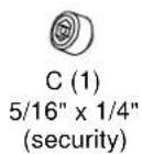
| Included Components | Ceiling plate (A), Set screw 5/16" x 1/4" (B), Security set screw 5/16" x 1/4" (C), Hex key (D), 4x 3/8" flat washers (E) |
| Required Fasteners (Not Included) | Two 3/8" x 2-1/2" lag screws (Grade 2 minimum) per installation |
| Installation Tools Required | 9/16" socket wrench, pipe wrench, drill with 1/4" bit, hex key, pencil |
| Cable Management | Integrated cable channel in ceiling plate |
| Safety Compliance | EN 60065:2002, CE, CSA |
| Use Environment | Indoor only |
| Warranty | 10 years limited warranty (estimated) |
| Dimensions (Approximate) | 6.5" x 4.5" x 2.25" (165 x 114 x 57 mm) |
| Weight (Approximate) | 5 lb (2.3 kg) |
| Mounting Hole Pattern | Opposite holes for lag screws (see manual for template) |
| Thread Engagement | Minimum 4 threads for extension column |
Frequently Asked Questions - CHCMS115 Chief
User questions about CHCMS115 Chief
0 question about this device. Answer the ones you know or ask your own.
Ask a new question about this device
Download the instructions for your Projector Accessory in PDF format for free! Find your manual CHCMS115 - Chief and take your electronic device back in hand. On this page are published all the documents necessary for the use of your device. CHCMS115 by Chief.
USER MANUAL CHCMS115 Chief
INSTALLATION INSTRUCTIONS

natural_image
Technical line drawing of a mechanical component with no visible text or symbolsCeiling Plate
DISCLAIMER
Milestone AV Technologies and its affiliated corporations and subsidiaries (collectively "Milestone"), intend to make this manual accurate and complete. However, Milestone makes no claim that the information contained herein covers all details, conditions or variations, nor does it provide for every possible contingency in connection with the installation or use of this product. The information contained in this document is subject to change without notice or obligation of any kind. Milestone makes no representation of warranty, expressed or implied, regarding the information contained herein. Milestone assumes no responsibility for accuracy, completeness or sufficiency of the information contained in this document.
Chief® is a registered trademark of Milestone AV Technologies. All rights reserved.

IMPORTANT SAFETY INSTRUCTIONS

WARNING: A WARNING alerts you to the possibility of serious injury or death if you do not follow the instructions.

CAUTION: A CAUTION alerts you to the possibility of damage or destruction of equipment if you do not follow the corresponding instructions.

WARNING: Failure to read, thoroughly understand, and follow all instructions can result in serious personal injury, damage to equipment, or voiding of factory warranty! It is the installer's responsibility to make sure all components are properly assembled and installed using the instructions provided.

WARNING: Failure to provide adequate structural strength for this component can result in serious personal injury or damage to equipment! It is the installer's responsibility to make sure the structure to which this component is attached can support five times the combined weight of all equipment. Reinforce the structure as required before installing the component.

WARNING: Exceeding the weight capacity can result in serious personal injury or damage to equipment! It is the installer's responsibility to make sure the combined weight of all components attached to the CMS115 does not exceed 500 lbs (227 kg).

WARNING: Use this mounting system only for its intended use as described in these instructions. Do not use attachments not recommended by the manufacturer.

WARNING: Never operate this mounting system if it is damaged. Return the mounting system to a service center for examination and repair.

WARNING: Do not use this product outdoors.
IMPORTANT ! : The CMS115 is designed to be mounted to 2" x 4" wood stud joists.
--SAVE THESE INSTRUCTIONS--
DIMENSIONS

DIMENSIONS: [MILLIMETERS] INCHES
LEGEND
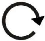 | Tighten Fastener |  | Pencil Mark |
| Apretar elemento de fijación | Marcar con lápiz | ||
| Befestigungsteil festziehen | Stiftmarkierung | ||
| Apertar fixador | Marcar com lápis | ||
| Serrare il fissaggio | Segno a matita | ||
| Bevestiging vastdraaien | Potloodmerkteken | ||
| Serrez les fixations | Marquage au crayon | ||
 | Loosen Fastener |  | Drill Hole |
| Aflojar elemento de fijación | Perforar | ||
| Befestigungsteil lösen | Bohrloch | ||
| Desapertar fixador | Fazer furo | ||
| Allentare il fissaggio | Praticare un foro | ||
| Bevestiging losdraaien | Gat boren | ||
| Desserrez les fixations | Percez un trou | ||
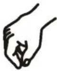 | By Hand |  | Optional |
| A mano | Opcional | ||
| Von Hand | Optional | ||
| Com a mão | Opcional | ||
| A mano | Opzionale | ||
| Met de hand | Optie | ||
| À la main | En option | ||
 | Hex-Head Wrench | 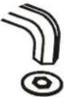 | Security Wrench |
| Llave de cabeza hexagonal | Llave de seguridad | ||
| Sechskantschlüssel | Sicherheitsschlüssel | ||
| Chave de cabeça sextavada | Chave de segurança | ||
| Chiave esagonale | Chiave di sicurezza | ||
| Zeskantsleutel | Veiligheidssleutel | ||
| Clé à tête hexagonale | Clé de sécurité | ||
 | Socket Wrench | ||
| Llave de cubo | |||
| Steckschlüssel | |||
| Chave de caixa | |||
| Chiave a brugola | |||
| Dopsleutel | |||
| Clé à douilles | |||
TOOLS REQUIRED FOR INSTALLATION
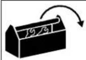


PARTS

natural_image
Technical line drawing of a mechanical component with no visible text or symbolsA (1) [Ceiling plate]


INSTALLATION

WARNING: Failure to provide adequate structural strength for this component can result in serious personal injury or damage to equipment! It is the installer's responsibility to make sure the structure to which this component is attached can support five times the combined weight of all equipment. Reinforce the structure as required before installing the component.
- Using ceiling plate (A) as a template, mark locations of two pilot holes (See Figure 1). Ensure the following:
• Use OPPOSITE holes in plate (A), and
- Marks are in the center of wood joist.
NOTE: Drywall not shown for clarity.
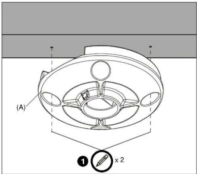
Figure 1
- Drill 1/4" diameter pilot holes into wood joist (See Figure 2). Ensure pilot holes are straight.

Figure 2
- Using 9/16" socket wrench, loosely install two (minimum) Grade 2 (not included) 3/8" x 2-1/2" lag screws through 3/8" washers (E), ceiling plate (A), into wood joist (See Figure 2). Do not tighten plate (A) against ceiling at this time to accommodate cable installation.
NOTE: Two additional washers are provided.
- Route cables through channel in ceiling plate (A) (See Figure 3).

Figure 3
- Tighten lag screws (See Figure 2).

WARNING: Exceeding the weight capacity can result in serious personal injury or damage to equipment! It is the installer's responsibility to make sure the combined weight of all components attached to the CMS115 does not exceed 500 lbs (227 kg).
-
Route cables through extension column (not included).
-
Using pipe wrench, install 1-1/2" NPT or NPSM following ANSI/ASME B1.20.1 (Schedule 40, 0.154" minimum thickness aluminum - ASTM B221) threaded extension column (not included) into threaded collar of ceiling plate (A) until tight, with a minimum of four threads engaged.
-
Using hex key (D), secure extension column by one of the following methods (See Figure 4):
-
Install one 5/16" x 1/4" set screw (B) into threaded hole, tightening firmly against column.
- OPTIONAL: Install one 5/16" x 1/4" security set screw (C) into threaded hole, tightening firmly against column.

Figure 4
milestone
AV Technologies
MANUFACTURERS DECLARATION OF CONFORMITY
For
Product identification:
Model/type : CMS115
Category (description) : Mounting devices, Stands and other Accessories, to be used with entertainment electronics
Brand : Chief
Manufacturer: Milestone AV Technologies
8401 Eagle Creek Parkway
Savage, MN 55378
EU Representative: Milestone AV Technologies
Fellennoord 130 5611
ZB Einhoven
The Netherlands
31 (0)20 5708923
| Concerning | ||||
| EMC | Safety | |||
| A sample of the product has been tested by: | Not Applicable CSAV Inc. | |||
| Test report reference | ||||
| Applied standards | EN 60065 :2002 | |||
Means of conformity
We declare under our sole responsibility that this product is in conformity with Directive 93/68/EEC (Marking), 98/37/EC (Machinery) 2001/95/EC (Safety) and/or complies to the essential requirements and all other relevant provisions of the based on test results using (non)harmonized standards in accordance with the Directives mentioned
Installation Instructions
Brand : Chief
Model : CHCMS115
Category : Projector Accessory