
LM-3115E - Screen Posiflex - Free user manual and instructions
Find the device manual for free LM-3115E Posiflex in PDF.


| Product Type | 15" TFT LCD Monitor (Bezel-free design) |
| Model Number | LM-3115E |
| Display Size | 15 inches |
| Resolution | 1024 x 768 pixels (XGA) |
| Contrast Ratio | 600:1 |
| Brightness | 350 cd/m² |
| Display Interface | VGA (15-pin D-Sub) |
| Power Supply | 12V DC, 40W (via included adapter or compatible POS terminal) |
| Touch Type | Non-touch (LM series) |
| Mounting | VESA mount compatible |
| Stand Features | Gen 7L base with tilt adjustment (flat folded, low profile, full extended) |
| OSD Controls | On-Screen Display with buttons for menu, adjust, and power |
| Optional Accessories | MSR side attachment (SL-105 for 15" models) |
| Package Contents | Monitor, VGA cable, USB cable (Type A to B), Power adapter, Information CD |
| Power LED Indicator | Solid blue (ON), Solid green (Standby), OFF (Power OFF) |
| Operating Conditions | Commercial environment (Class A digital device) |
| Weight & Dimensions | Not specified in manual, but typical for 15" POS monitor ~4-5 kg |
| Cleaning and Maintenance | Clean with soft, dry cloth; avoid pressing on LCD panel |
| Safety Warnings | Use grounded outlet; do not open device; follow instructions to avoid warranty void |
Frequently Asked Questions - LM-3115E Posiflex
User questions about LM-3115E Posiflex
0 question about this device. Answer the ones you know or ask your own.
Ask a new question about this device
Download the instructions for your Screen in PDF format for free! Find your manual LM-3115E - Posiflex and take your electronic device back in hand. On this page are published all the documents necessary for the use of your device. LM-3115E by Posiflex.
USER MANUAL LM-3115E Posiflex

Package Contents
9.7" LM/TM-3X10E or 14" LM/TM-3X14E or 15" LM/TM-3X15E
Standalone POS Monitor....(x 1)
√ VGA Cable....(x 1)
√ USB type A to B cable....(x 1)
(For TM series monitors Only)
√ Power Adapter....(x 1)
√ Information CD
(for TM series monitors Only)......(x 1)
Product Features
For LM-31XXE/33XXE models
● LM-31XXE with slim bezel-free design; LM-33XXE with slim bezel-type design
● 9.7" or 15" TFT LCD panel or 14" wide screen TFT LCD panel
● VESA mounting support
For TM-31XXE/33XXE models
● TM-31XXE with slim bezel-free design; TM-33XXE with slim design
● 9.7" or 15" TFT LCD panel or 14" wide screen TFT LCD panel
● P-CAP touch panel for TM-31XXE; 5-wire resistive touch panel for TM-3315E
- VESA mounting support
- Optional side attachment support for LM/TM-3X15E (SL-105)
- Optional side attachment support for LM/TM-3114E (SL-104)
TM/LM-31xxE/33xxE Ver. B0
FCC NOTES
This system meets industry & government requirements and applicable standards. This equipment generates, uses, and can radiate radio frequency energy and, if not installed and used in accordance with the instructions manual, may cause interference to radio communications. It has been tested and found to comply with limits for a Class A digital device pursuant to subpart B of Part 15 of FCC Rules, which are designed to provide reasonable protection against interference when operated in a commercial environment. Operation of this equipment in a residential area is likely to cause interference in which case the user at his own expense will be required to take whatever measures to correct the interference.
This device complies with part 15 of the FCC Rules. Operation is subject to the following two conditions: (1) This device may not cause harmful interference, and (2) this device must accept any interference received, including interference that may cause undesired operation.
CE CLASS A WARNING
This equipment is compliant with Class A of CISPR 32. In a residential environment this equipment may cause radio interference.
AVERTISSEMENT CE CLASSE A
Warranty will terminate automatically when the machine is opened by any person other than the authorized technicians. The user should consult his/her dealer for the problem happening. Warranty voids if the user does not follow the instructions in application of this merchandise. The manufacturer is by no means responsible for any damage or hazard caused by improper application.
LIMITES DE GARANTIE
Power cord shall be connected to a socket-outlet with earthing connection.
ATTENTION
9.7" LM-3110E LCD Panel
9.7" TM-3110E P-Cap Touch Panel

Rear View
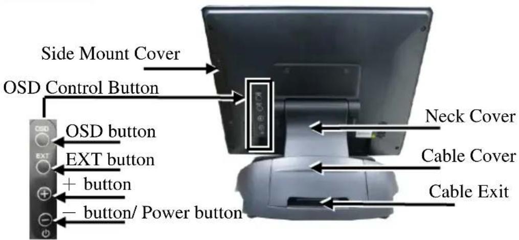
OSD Control Button

Bottom View
I/O Ports of LM-3X10E

I/O Ports of TM-3X10E

Views of the LM/TM-3114E
Front View
14" LM-3114E LCD Panel
14" TM-3114E P-Cap Touch Panel

Rear View

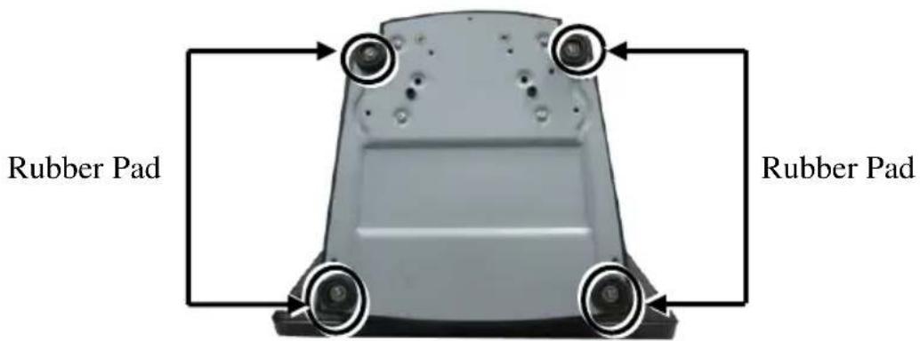
Bottom View

Rubber Feet with Fixing Screw
I/O Ports

Views of the LM/TM-3115E/3315E
Front View
15" LM-3315E LCD Panel
15" TM-3315E Resistive Touch Panel
15" LM-3115E LCD Panel
15" TM-3115E P-Cap Touch Panel

Rear View
Bottom View

Rubber Feet with Fixing Screw
I/O Ports

Positioning your monitor for a Perfect Viewing Angle 9.7" LM/TM-3110E/ 3310E
With simpler and lighter design, the miniature standalone base for 9.7" LM-3110E/TM-3310E makes it easy for you to set up the tilt angle. Please refer to below suggestion to tilt your monitors:
To find the ideal viewing angle for 9.7" LM/TM series monitors, please adjust the monitor up or down in the direction indicated by the arrow. Be careful NOT to touch the panel while tilting the screen.

14" or 15" LM/TM-31XXE/33XXE
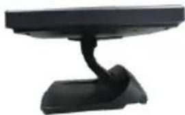
Different from the miniature base used by 10" LM/TM series monitors, the adjustable Gen 7L base featuring its unique tilt adjustment mechanism allows you to determine an ideal position for 14" and 15" LM/TM-31XXE/33XXE series monitors. In general, it provides three standard positioning solution as the below figures suggested: flat folded mode, low profile mode, and full extended mode.
14" or 15" LM/TM-31XXE/33XXE with Gen 7L Base
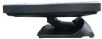
Flat folded mode

Low profile mode

Full extended mode
LM/TM-31XXE/33XXE will be set up beforehand in flat folded mode before being packaged into the box for shipping. After it is unpacked, you may re-adjust the monitor in either low profile mode or full extended mode according to your situation. The following describes the steps of adjusting Gen 7L base connected to the monitor among different positioning modes.
-
Unpack LM/TM-31XXE/33XXE, which is supposed to be set in flat folded mode, out of the package box and then lay your POS system on a flat surface.
-
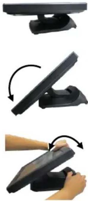
Steady the base stand with one hand, and then tilt the screen downwards.


- Position your monitor in Full Extended mode.
3.1 After grabbing the bottom edge of the screen with your hand, gently move the screen upward until the screen is locked into place with a click sound.

3.2 With the screen facing toward you, tilt the screen up or down to your desired angle. Please do not press on the LCD panel while setting up the tilt angle.

- Restore your monitor to Flat Folded mode from Full Extended mode.
4.1 Tilt your screen in a horizontal position. Then, remove the cable cover from the base stand.
4.2 Support the screen with one hand holding onto its bottom edge. While pulling the lever backwards, move the screen downwards until the lever is lifted off the hook as shown in the figure

4.3 Push the cable cover back.
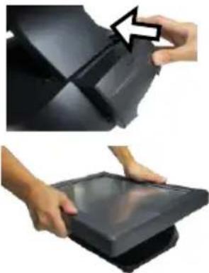
4.4 Tilt the screen again to the horizontal position.
- Position the monitor in Low Profile mode.
5.1 Follow Step 4 to set up the monitor in Flat Folded mode.
5.2 Tilt the screen all the way down
5.3 To tilt screen up or down to your desired angle, please be advised to keep the base stand steady with one hand to do so. Do NOT press on the LCD panel while setting up the tilt angle.
Connecting VGA and USB Cables
The following section will provide the instructions on how to connect power adapter, VGA and USB type A to B cables, and introduce helpful cable-routing tips you may need to use while organizing cables.
For TM-31XXE/33XXE users, please note that USB type A to B cable needs to be well attached to both of your monitor and terminal to allow touch screen function to work normally.
- Lay the monitor with its rear facing toward you and tilt the screen all the way down.

9.7" LM/TM-3110E/3310E

14" or 15" LM/TM-31XXE/33XXE
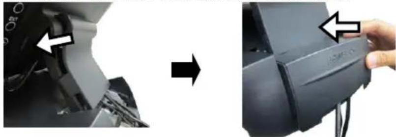
- Adjust the screen downwards, and release the cable cover from the base.
For 9.7" LM/TM-3110E/3310E monitors, please directly remove the neck cover from the base.
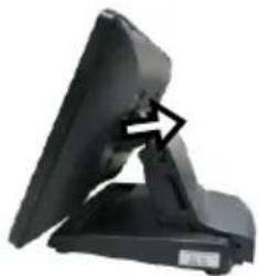
If you are using 14" or 15" LM/TM-series monitors, refer to the below figures to first remove cable cover and then neck cover in the direction shown by the arrow.

- After adjusting the screen to the horizontal position, take one end of the VGA cable and have it passed through the cable exit.
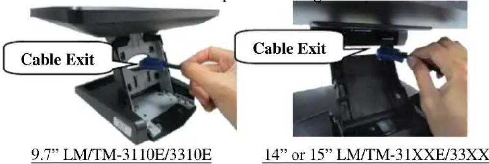
- Secure the VGA cable to the VGA port at the bottom I/O plate of your monitor.

- Grab Type-B connector of USB cable to route it through the cable, and then insert it into Type-B USB port of your monitor.

- If you intend to use Power adapter to supply power to your monitor, thread the cable of power adapter through cable exit, connect it to DC-IN power connector of the monitor and then another end to the electrical outlet.

- Move the screen all the way down. Then, place back the cover into place.
For 9.7" LM/TM-3110E/3310E users, please place the neck cover back into place.

If you are using 14" or 15" LM/TM series monitors, first push back the neck cover and then slide back the cable cover.
- Properly attach Type-A connector of USB cable and VGA cable to your POS terminal.
Installing an Magnetic Stripe Reader (Optional)
To expand functionality of your monitors, it allows you to additionally mount an optional magnetic stripe reader (MSR), SL-104 for LM/TM-3114E models or SL-105 for LM/TM-3X15E models. Before installing the peripheral device, make sure that the monitor is properly powered off and is disconnected from the external power source. For the detailed installation instructions of MSR, please be advised to refer to the relevant user manual.
Identifying your monitor as secondary touchscreen monitor in extended mode
Based on the type of your touch panels, you are required to adopt different approaches to set up TM series as the extended monitor when you attempt to extend the desktop across multiple monitors. In the following section the related descriptions will be offered to help you achieve the purpose.
For TM-3315E Model with Resistive Touchscreen
For TM-3315E users, please follow the below instructions to complete installation of The Dual Touch Manager, a tool designed to allow your monitor to work as a secondary touchscreen monitor in extended mode.
- Make sure that the monitor is well connected to your POS terminal with USB type A to B cable.
- Insert the Peripheral Information CD, which is included in the package, into your CD-ROM. Locate and double click the index file.
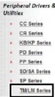
- Click on Peripheral Drivers & Utilities.
- Click on TM/LM Series at the left side of the menu.

Posiflex Peripheral Drivers & Manuals v1.3

- Click on the Setup icon of USB Dual Touch Manager to install the USB Dual Touch Manager.
TM Series
| Description | Version | Setup |
| USB Dual Touch Manager | 3.03 | |
| USB Single Touch Manager | 2.07 | |
| USB Monitor Driver | 7.6 |
- Follow the instructions to complete the manager installation. After the installation is finished, restart your terminal.
For TM-31XXE Models with P-CAP Touchscreen
If your monitors are TM-31XXE models, you may configure the display settings from Control Panel in Microsoft Windows to identify the monitor as the secondary touchscreen monitor. Please go through the below steps to complete configuration.
- Make sure that the monitor is well connected to your POS terminal with USB type A to B cable.
- Go to Control Panel>Display Settings, change your display settings to extended mode.
-
Go to Control Panel, and then click on Tablet PC Settings item.
-
In Tablet PC Settings dialogue box, click on Setup button.


- Following the instruction shown on the screen, click on the screen that you want to identify as the primary touchscreen display.
Touch this screen to identify it as the touchscreen.
If this is not the Tablet PC screen, press Enter to move to the next screen. To close the tool, press Esc
- Press Enter button to proceed the configuration.
Press Enter to proceed to the next step to complete your configuration
- Click on the screen you want to use as the secondary touchscreen display.
Touch this screen to identify it as the touchscreen.
If this is not the Tablet PC screen, press Enter to move to the next screen. To close the tool, press Esc.
Powering ON/OFF your Monitor
To start up LM/TM-31XXE/33XXE, you have to make sure that the monitor is well connected to POS terminals and electricity is supplied to the monitor either through POS terminal or through external power sources. For the users who prefer Posiflex POS terminal as primary power sources to power your monitor using VGA cable, please also refer to the Activating Power Output to VGA Port via BIOS Settings section to confirm that VGA port of your terminal is indeed enabled.
Power ON LM/TM-31XXE/33XXE
Press the power button of the terminal to power up the terminal. Few seconds later the monitor will be initiated automatically.
Power OFF LM/TM-31XXE/33XXE
After following the standard shutdown procedure to shut down your terminal, the monitor will be consequently turned off.
Activating Power Output to VGA port via BIOS Settings
In general, Posiflex terminals will disable the VGA controller in BIOS due to safety concerns. In the case of using your terminal to supply power to monitors, it is required to manually enable the VGA output of the terminals in BIOS settings so that the monitor is able to extract power from the Posiflex terminals. However, if the monitor you are using is not manufactured by Posiflex, it is strongly suggested to deactivate the VGA port of your terminal in preventing your device from being damaged.
The following will describe the steps required to enable VGA port in BIOS setting. For those users who intend to power the monitors using power adaptor included in your package, you may skip this section. Besides, please DO NOT plug the VGA cable into VGA connectors while the terminal is still running.
- Make sure that LM/TM-31XXE/33XXE is well connected to the Posiflex terminals using the VGA cable.
- Press the power button of the POS to power on the POS. During the boot process, hit F2 key to access BIOS setting.
- Navigate through BIOS using arrow and Enter keys to access the setting of VGA port. If it is set to be disabled, hit Enter key to enable the VGA port.
- Switch to Exit tab and select Exit Saving Changes option. Choose Yes in Setup Confirmation message box to save your configurations.
- After rebooting your POS, make sure the monitor is correctly detected.
Power LED Indicator
Power LED indicator, which is either located at the bottom of the screen or on bottom I/O plate depending on your model type, is used to notify users of the current status of your monitor by emitting various LED signals. Please refer to the below chart to accurately interpret the of the indicators status to facilitate your troubleshooting.
9.7" LM/TM-3X10E or 14" LM/TM-3114E
| Status | Description |
| ON, solid green | System power ON |
| ON, solid orange | System Standby |
| OFF | System power OFF |
15" LM/TM-3X15E
| Status | Description |
| ON, solid blue | System power ON |
| ON, solid green | System Standby |
| OFF | System power OFF |
Setting up Display Resolution for Your Monitor
The below chart defines the list of recommended display settings for LM/TM-31XXE/33XXE. Improper display configuration will prevent the monitor from properly displaying the image and lead to a warning message of “out of range” prompted on the screen.
14" LM/TM-3114E
| Display Resolution | Horizontal Frequency (KHz) | Refresh Rate (Hz) |
| 640 x 480 | 31.47 | 60.00 |
| 800 x 600 | 37.88 | 60.32 |
| 1024 x 768 | 48.36 | 60.00 |
| 1280 x 720 | 45.00 | 60.00 |
| 1360 x 768 | 47.71 | 60.01 |
| 1366 x 768 | 47.71 | 59.79 |
9.7" LM/TM-3X10E or 15" LM/TM-3X15E
| Display Resolution | Horizontal Frequency (KHz) | Refresh Rate (Hz) |
| 640 x 400 | 37.9 | 70 |
| 640 x 480 | 31.5 | 60 |
| 37.9 | 72 | |
| 37.5 | 75 | |
| 720 x 400 | 37.9 | 70 |
| 800 x 600 | 35.1 | 56 |
| 37.9 | 60 | |
| 48.1 | 72 | |
| 46.9 | 75 | |
| 1024 x 768 | 48.4 | 60 |
| 56.5 | 70 | |
| 60 | 75 |
Using the OSD Menu
OSD, as known as On-Screen Display, is employed to assist users in adjusting a variety of monitor-related settings depending on personal preference.
Through this section, it is expected to familiarize you with the options which are accessible via OSD menu, and to optimize your experiences with LM/TM-31XXE/33XXE.
Power & OSD Buttons
Power & OSD buttons are available on the rear, right-hand side of the LCD monitor. Each of four OSD controls works differently in various occasions. Please refer to the below figure to get an idea of how they could possibly function in relation to OSD menu.
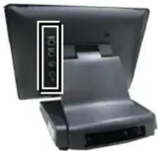
| Icon | Description | |
 | OSD button | ● to activate the OSD menu● to select the specific menu option |
 | EXT button | ● to exit from the current configuration |
 | “+” Button | ● to navigate through OSD menu options● to increase the value of the specific item● auto-adjustment feature |
 | ‘-”Button/Power Button | ● to navigate through OSD menu options● to decrease the value of the specific item● turn on/off the monitor |
To help you get started with the OSD menu, the following points are guidelines you are suggested to go through:
- Firstly, press the OSD button to access the OSD menu.
- Scroll through OSD menu options using either the “+” or “-” button.
- Press the OSD button to select the particular menu option of interest. It will lead you to its sub-menu page if the selected menu option contains sub-menu items.
- Under the selected menu item with available sub-menu items, use the “+” or “−” button to switch among different items. Then, press the OSD button to select the sub-menu item which you intend to adjust.
- Use the “+” or “−” button to adjust the value of the selected OSD item. Then, press the OSD button to save settings.
- Press the EXT button to exit from the current configuration.
OSD Options
Please refer to the following table for further explanation of the accessible items.
| OSD Menu Options | Sub-menu items & Description | |
 | Picture | BacklightPress the “+” button to increase backlight intensity;Press the “-” button to decrease backlight intensity.BrightnessPress the “+” button to increase brightness;Press the “-” button to decrease brightness.ContrastPress the “+” button to increase contrast;Press the “-” button to decrease contrast.SharpnessPress the “+” button to increase sharpness;Press the “-” button to decrease sharpness. |
 | Display | Auto AdjustmentExecute the auto-tune function for OSD menu, which will automatically perform fine tune of the image quality for optimizing screen performance.H PositionPress the “+” button to move the screen to the right;Press the “-” button to move the screen to the left.V PositionPress the “+” button to move the screen up;Press the “-” button to move the screen down.Pixel ClockUse the “+” or “-” button to adjust theClock setting for VGA input.PhaseUse the “+” or “-” button to adjust thePhase setting for VGA input. |
| OSD Menu Options | Sub-menu items & Description |
 Other Other | ResetRestore the current menu back to the default setting.Menu TimeSpecify the length of time for OSD menu to stay active on the screen.LanguageSpecify the language used in the OSD menu. |
 Information Information | Display information regarding display resolution, horizontal/vertical sync frequency, pixel clock (PCLK), etc. |
Specifications LM-31XXE/33XXE Models
| LM-3110E | LM-3114E | LM-3115E | LM-3310E | LM-3315E | |
| Display | |||||
| LCD Panel | 9.7" TFT LCD | 14" TFT LCD | 15" TFT LCD | 9.7" TFT LCD | 15" TFT LCD |
| Resolution (H) x (V) | 1024 x 768 | 1366 x 768 | 1024 x 768 | ||
| Contrast Ratio | 500 : 1 | 650 : 1 | 600 : 1 | 500 : 1 | 600 : 1 |
| Brightness | 270 cd/m2 | 200 cd/m2 | 350cd/m2 | 270 cd/m2 | 350cd/m2 |
| Touch | |||||
| Touch type | N/A | ||||
| Interface | N/A | ||||
| General Specification | |||||
| Display Interface | VGA | ||||
| Power Supply | 12V / 18W | 12V / 40W | 12V / 18W | 12V / 40W | |
TM-31XXE/33XXE Models
| TM-3110E | TM-3114E | TM-3115E | TM-3315E | |
| Display | ||||
| LCD Panel | 9.7" TFT LCD | 14" TFT LCD | 15" TFT LCD | |
| Resolution (H) x (V) | 1024 x 768 | 1366 x 768 | 1024 x 768 | |
| Contrast Ratio | 500 : 1 | 650 : 1 | 600 : 1 | |
| Brightness | 270 cd/m2 | 200 cd/m2 | 350cd/m2 | 300cd/m2 |
| Touch | ||||
| Touch type | Bezel-free P-CAP touch panel | 5-wire Resistive touch panel | ||
| Interface | USB | |||
| General Specification | ||||
| Display Interface | VGA | |||
| Power Supply | 12V / 18W | 12V / 40W | ||
※ The product information and specifications are subject to change without prior notice. To get the detailed information on LM/TM-31XXE/33XXE, please check this model from Posiflex Global Website.


- PACKAGE CONTENTS
- PRODUCT FEATURES
- FOR LM-31XXE/33XXE MODELS
- FOR TM-31XXE/33XXE MODELS
- FCC NOTES
- CE CLASS A WARNING
- AVERTISSEMENT CE CLASSE A
- LIMITES DE GARANTIE
- ATTENTION
- REAR VIEW
- VIEWS OF THE LM/TM-3114E
- FRONT VIEW
- BOTTOM VIEW
- VIEWS OF THE LM/TM-3115E/3315E
- I/O PORTS
- POSITIONING YOUR MONITOR FOR A PERFECT VIEWING ANGLE 9.7" LM/TM-3110E/ 3310E
- 14" OR 15" LM/TM-31XXE/33XXE
- 14" OR 15" LM/TM-31XXE/33XXE WITH GEN 7L BASE
- CONNECTING VGA AND USB CABLES
- INSTALLING AN MAGNETIC STRIPE READER (OPTIONAL)
- IDENTIFYING YOUR MONITOR AS SECONDARY TOUCHSCREEN MONITOR IN EXTENDED MODE
- FOR TM-3315E MODEL WITH RESISTIVE TOUCHSCREEN
- FOR TM-31XXE MODELS WITH P-CAP TOUCHSCREEN
- POWERING ON/OFF YOUR MONITOR
- POWER ON LM/TM-31XXE/33XXE
- POWER OFF LM/TM-31XXE/33XXE
- ACTIVATING POWER OUTPUT TO VGA PORT VIA BIOS SETTINGS
- POWER LED INDICATOR
- SETTING UP DISPLAY RESOLUTION FOR YOUR MONITOR
- USING THE OSD MENU
- POWER & OSD BUTTONS
- OSD OPTIONS
Brand : Posiflex
Model : LM-3115E
Category : Screen