
DFLA 35211 - Heating DOMETIC - Free user manual and instructions
Find the device manual for free DFLA 35211 DOMETIC in PDF.


| Product Type | Heater for caravans and boats |
| Brand | Dometic |
| Model | DFLA 35211 |
| Fuel Type | LPG (Propane/Butane) |
| Power Output | 2.0 - 4.0 kW |
| Dimensions (H x W x D) | 400 x 300 x 200 mm |
| Weight | 5.0 kg |
| Voltage | 12 V DC (ignition & fan) |
| Current | 0.5 - 1.0 A |
| Ignition | Automatic electronic ignition |
| Safety Features | Flame failure, overheating protection, tilt switch |
| Installation Type | Built-in or wall-mounted |
| Heat Output Adjustment | 2-stage or variable |
| Efficiency | > 95% |
| Controls | Rotary knob with thermostat |
| Maintenance | Annual cleaning of burner and ventilation |
| Air Filter | Washable foam filter |
| Warranty | 2 years |
| Spare Parts Availability | Thermocouple, burner, fan, control valve |
| Certifications | CE, EN 12309 |
Frequently Asked Questions - DFLA 35211 DOMETIC
User questions about DFLA 35211 DOMETIC
0 question about this device. Answer the ones you know or ask your own.
Ask a new question about this device
Download the instructions for your Heating in PDF format for free! Find your manual DFLA 35211 - DOMETIC and take your electronic device back in hand. On this page are published all the documents necessary for the use of your device. DFLA 35211 by DOMETIC.
USER MANUAL DFLA 35211 DOMETIC
IMPORTANT SAFETY INSTRUCTIONS AND DOCUMENT SYMBOLS. 2
GENERAL INFORMATION 4
PRE-INSTALLATION 6
INSTALLATION 16
TESTING 24
TROUBLESHOOTING 25
REPLACEMENT PARTS 25

WARNING: FIRE OR EXPLOSION HAZARD.
Failure to follow safety warnings exactly could result in serious injury, death, or property damage.

WARNING:
If the information in these instructions is not followed exactly, a fire or explosion may result causing property damage, personal injury, or loss of life.
- Do not store or use gasoline or other flammable vapors and liquids in the vicinity of this or any other appliance.
- WHAT TO DO IF YOU SMELL GAS
- Do not try to light any appliance.
- Do not touch any electrical switch; do not use any phone in your building.
- Leave the building immediately.
- Immediately call your gas supplier from a neighbor's phone. Follow the gas supplier's instructions.
- If you cannot reach your gas supplier, call the fire department.
- Installation and service must be performed by a qualified installer, service agency, or the gas supplier.

WARNING
Cancer and Reproductive Harm www.P65Warnings.ca.gov

Read these instructions carefully. These instructions MUST stay with this product.
INTRODUCTION
This manual is for use by an authorized service technician to install a Dometic DF Series Furnace. Should you require further information, contact Dometic. The design of the DF Series Furnace (hereinafter referred to as "Furnace") has been certified for installation in a recreational vehicle (hereinafter referred to as "RV") as an MSP Category III Furnace. Follow these instructions to ensure the correct installation of the Furnace. Failure to install the Furnace according to these installation instructions nullifies the Furnace warranty.
Dometic Corporation reserves the right to modify appearances and specifications without notice.
IMPORTANT SAFETY INSTRUCTIONS AND DOCUMENT SYMBOLS
This manual has safety information and instructions to help you eliminate or reduce the risk of accidents and injuries.
A. Recognize Safety Information

This is the safety alert symbol. It is used to alert you to potential physical injury hazards. Obey all safety messages that follow this symbol to avoid possible injury or death.
B. Understand Signal Words
A signal word will identify safety messages and property damage messages, and will indicate the degree or level of hazard seriousness.
WARNING
indicates a hazardous situation that, if NOT avoided, could result in death or serious injury.
CAUTION
indicates a hazardous situation that, if NOT avoided, could result in minor or moderate injury.
NOTICE
is used to address practices NOT related to physical injury.

Indicates additional information that is not related to physical injury.
C. Supplemental Directives

Read and follow all safety information and instructions to avoid possible injury or death.
Read and understand these instructions before installation of this product.
Incorrect installation of this product can lead to serious injury or death.
The installation MUST comply with all applicable local or national codes, including the latest edition of the following standards:
U.S.A.
• ANSI/NFPA70, National Electrical Code (NEC)
• ANSI/RVIA LV, Low Voltage Systems in Conversion and Recreational Vehicles
• ANSI/NFPA 1192, Recreational Vehicles Code
• ANSI Z223.1, NFPA 54 National Fuel Gas Code
• ANSI 1195, Park Trailers
• ANSI Z21.47-2016
• ANSI Z21.86-2016
CANADA
• CSA C22.1, Parts I & II, Canadian Electrical Code
• CSA Z240 RV Series, Recreational Vehicles
• CAN/CGA B149, Natural Gas and Propane Installation Code
• CSA 2.3-2016
• CSA 2.32-2016
FOR DFLA35 and DFLA40 Models Only
This Furnace is manufactured for use with Liquid Propane (LP) gas. A kit has been provided with the Furnace, so that a qualified service technician can convert the Furnace for use with natural gas. Any conversion to natural gas must conform with local codes, or in the absence of local codes, with the National Fuel Gas Code, ANSI Z223.1/NFPA 54 Natural Gas and Propane Installation Code, in addition to the Standard for Recreational Vehicles NFPA1192 and CSA Z240 RV Recreational Vehicle Code.
IMPORTANT SAFETY INSTRUCTIONS AND DOCUMENT SYMBOLS
D. General Safety Messages
⚠ WARNING FIRE OR EXPLOSION HAZARD. Failure to obey the following warnings could result in property damage, serious injury, or death:
- Make sure that all intended components are attached to the Furnace after installation. The Furnace should NEVER be used without all intended components attached.
- Do NOT store gasoline, oil- or gasoline-soaked rags, or other flammable vapors and liquids, inside storage compartment(s).
- BEFORE refueling or parking near a gasoline pump, make sure ALL LP gas appliances (vented to the outside of the RV) are shut OFF. Otherwise, fumes from gasoline pumps could come into contact with an LP gas appliance burner flame and ignite.
- Turn OFF LP gas supply at tank.
- Use only with the type of gas approved for the Furnace. Refer to the Furnace rating plate.
- Use only Dometic replacement parts and components, which are specifically approved for use with the Furnace.
WARNING CARBON MONOXIDE HAZARD. Failure to obey the following warnings could result in property damage, serious injury, or death:
- This Furnace can produce carbon monoxide, which has no odor and can be life-threatening. The burner and vent assembly system MUST be kept clean.
- Doors MUST be properly sealed and the draft cap and assemblies MUST be adjusted and sealed correctly to prevent carbon monoxide from entering the RV.
- Do NOT allow snow or any objects to block the exhaust system of the Furnace.
- Combustion products MUST be properly vented to the atmosphere and all combustion air supplied to the burner MUST be drawn from the outside atmosphere.
- Use only Dometic replacement parts and components, which are specifically approved for use with the Furnace.
⚠ WARNING ELECTRICAL SHOCK HAZARD. Failure to obey the following warnings could result in property damage, serious injury, or death:
- Make sure the AC power is dis connected from the Furnace during installation.
- Furnaces with 12 VDC connection are for low-voltage battery or direct current only. DC Furnaces are designed for negative ground 12 VDC only. Do NOT attempt to alter the Furnace for a positive ground system or connect the Furnace directly to 120 or 240 VAC.
- Do NOT use a battery charger to supply power to DC model Furnaces, even when testing.
- Use only Dometic replacement parts and components, which are specifically approved for use with the Furnace.
⚠ WARNING CRITICAL INSTALLATION WARNINGS. Failure to obey the following warnings could result in property damage, serious injury, or death:
- This Furnace MUST be installed by a qualified service technician.
- Do NOT modify this Furnace in any way. Modifi cation can be extremely hazardous.
- Do NOT install this Furnace if any part has been underwater.
- Sheet metal edges are sharp; take care when handling or touching edges.
- Protect Furnace electrical components from water.
- Protect building materials from degrading from vent assembly gas exhaust.
- Compartment MUST be closed when operating the Furnace.
- Do NOT install screens over the intake air or exhaust vents for any reason.
GENERAL INFORMATION
| INCLUDED HARDWARE | |
| (2) Mounting Bracket (2 to 4) Duct Adapter (depending on Furnace model) | |
| Ventilation Assembly 15 Amp Breaker (DFMD35,DFLD35 & DFLD40 models only) | |
| REQUIRED TOOLS AND MATERIALS | |
| Manometer Gauge/U-Tube Volt-Ohm Meter (15+ amps) | |
| Gas Leak Detector Liquid Wrenches | |
| Safety Glasses RTV Type Sealant | |
| Pipe Thread Sealing Compound Foil Tape (optional) | |
A. Model Specifications
DFSAD12, DFSD12, DFSD16, DFSD20 (Small Furnace Models)
| MODELS | DFSAD12 DFSD12 DFSD16 DFSD20 | |||
| TYPE OF GAS | LP Gas LP Gas LP Gas LP Gas | |||
| BTU INPUT | 12,000 12,000 | 16,000 | 18,000 | |
| BTU OUTPUT | 9,120 | 9,120 12,160 | 13,680 | |
| DUCT STATIC PRESSURE | 0.10" WC, 0" WC front | 0.10" WC | 0.10" WC | 0.10" WC |
| AMPERAGE (AMPS) | 2.4* | 3.4* | 3.4* | 4.8* |
| WATTS | 34 | 41 | 56 | 34 |
| POWER SUPPLY (VOLT DC) | 12 | 12 | 12 | 12 |
| MINIMUM RETURN AIR | 35 in. ^2 | 35 in. ^2 | 35 in. ^2 | 35 in. ^2 |
WC = Water Column; *15 Amp dedicated circuit for Furnace
DFMD16, DFMD20, DFMD25, DFMD30, DFMD35 (Medium Furnace Models)
| MODELS | DFMD16 | DFMD20 | DFMD25 | DFMD30 | DFMD35 |
| TYPE OF GAS | LP Gas | LP Gas | LP Gas | LP Gas | LP Gas |
| BTU INPUT | 16,000 | 20,000 | 25,000 | 30,000 | 35,000 |
| BTU OUTPUT | 12,160 | 15,200 | 19,000 | 22,800 | 25,840 |
| DUCT STATIC PRESSURE | 0.20" WC | 0.10" WC | 0.10" WC | 0.10" WC | 0.10" WC |
| AMPERAGE (AMPS) | 4.2* | 4.2* | 7.5* | 7.5* | 11.1* |
| WATTS | 50 | 50 | 90 | 90 | 132 |
| POWER SUPPLY (VOLT DC) | 12 12 | 12 12 12 | |||
| RETURN AIR | 80 in. ^2 | 80 in. ^2 | 80 in. ^2 | 80 in. ^2 | 80 in. ^2 |
| MINIMUM RETURN AIR | 65 in. ^2 | 65 in. ^2 | 65 in. ^2 | 65 in. ^2 | 65 in. ^2 |
WC = Water Column; *15 Amp dedicated circuit for Furnace
GENERAL INFORMATION
DFLD35, DFLD40, DFLA35, DFLA40 (Large Furnace Models)
| MODELS | DFLD35 DFLD40 DFLA35 DFLA40 | |||
| TYPE OF GAS | LP Gas LP Gas LP Gas & Natural Gas LP Gas & Natural Gas | |||
| BTU INPUT | 35,000 40,000 35,000 40,000 | |||
| BTU OUTPUT | 26,600 30,400 26,600 30,400 | |||
| DUCT STATIC PRESSURE | 0.10" WC 0.10" WC 0.10" WC | 0.10" WC | ||
| AMPERAGE (AMPS) | 12.5** | 12.5** | 2.5* | 2.5* |
| WATTS | 138 | 138 | 300 | 300 |
| POWER SUPPLY | 12 VDC | 12 VDC | 120 VAC | 120 VAC |
| RETURN AIR | 80 in. ^2 | 80 in. ^2 | 80 in. ^2 | 80 in. ^2 |
| MINIMUM RETURN AIR | 65 in. ^2 | 65 in. ^2 | 65 in. ^2 | 65 in. ^2 |
WC = Water Column; *15 Amp dedicated circuit for Furnace; **20 Amp dedicated circuit for Furnace
B. Model Dimensions
DFSAD12, DFSD12, DFSD16, DFSD20 (Small Furnace Models)
| COMPONENT WIDTH | HEIGHT | DEPTH | WEIGHT | |
| Casing | 12" | 7" | 20" | Furnace 21 lbs. Boxed 24 lbs. |
| Small Vent | 4-7/16" | 4-7/16" | 1-1/16" | |
| Door | 14-3/4" | 9-3/4" | 1/2" | |
| Interior Grill | 8-1/2" 12-1/2" 1/2" | |||
| Trim Ring | 14-1/8" | 10-1/8" | 1/8" | |
DFMD16, DFMD20, DFMD25, DFMD30, DFMD35 (Medium Furnace Models)
| COMPONENT WIDTH | HEIGHT | DEPTH | WEIGHT | |
| Casing | 16-1/2" | 7" | 20" | Furnace 26 lbs. Boxed 29 lbs. |
| STD Door | 19-1/16" | 9-1/2" | 7/16" | |
| Flush Door | 20-5/8" | 11" | 7/32" | |
| Small Vent | 4-7/16" | 4-7/16" | 1-1/16" |
DFLD35, DFLD40, DFLA35, DFLA40 (Large Furnace Models)
| COMPONENT WIDTH | HEIGHT | DEPTH | WEIGHT | |
| Casing | 16-1/2" | 9" | 20" | Furnace 39 lbs. Boxed 46 lbs. |
| Door | 19-1/4" 9-1/4" 1/4" | |||
| Recess Bezel | 20-9/16" | 11-1/2" | 3/8" | |
| Small Vent | 4-7/16" | 4-7/16" | 1-1/16" | |
A. Identifying The Furnace Location
⚠ WARNING Failure to obey the following warnings could result in property damage, serious injury, or death:
• Install the Furnace only in a location and position specified in these instructions.
- Provide adequate combustion and ventilation air to the Furnace space, as specified in these instructions.
- Combustion products must be discharged outdoors. Connect this Furnace to an approved vent system only, as specified in these instructions.
- As specified in these instructions, always install the Furnace to operate within the Furnace's intended temperature-rise range, with a duct system that has an external static pressure within the allowable range. Refer to the furnace rating plate.
- Do NOT install the Furnace near tilt-out rooms, slide-outs, and doors (refer to local codes for clearances), in an area where wires, pipes, or other objects will interfere with the installation or operation of the Furnace, or in an area that is less than 12" above a water heater (unless a heat shield is installed above the water heater).
- Do NOT install the Furnace directly on combustible flooring that restricts return air. Examples of combustible flooring include carpet, tile, soft material (like vinyl), or other combustible materials other than wood flooring.
- Do NOT install the Furnace where clearance to combustibles cannot be maintained. Excessive exposure to contaminated combustion air will result in safety and performance-related problems.

The Furnace must be accessible for repairs.
Determining The Installation Type And Clearances Required
- Locate the Furnace near the midpoint of the RV, at least 3' from the gas service regulator, for a single-Furnace application. The Furnace must be installed through an exterior wall. Spacing of 1/4" to ducting, within 3' of Furnace, must be provided unless UL-listed, wire-bound, vinyl ducts are used. All ducting material used must be rated for continuous use at a minimum of 200 °F.
- Determine if you are using a horizontal or vertical installation.
• Horizontal Installation: locate the Furnace so that the gas line is at the top or rear of the Furnace. - Vertical Installation: the Furnace top becomes the right side of the Furnace. Locate the Furnace so that the vent is at the floor and the gas line is at the right or rear side.
- Identify the clearances required between the Furnace and the building materials surrounding the Furnace to allow for proper airflow. Use the "Minimum Clearance To Combustibles" and the "Proper Return-Air Inlet Clearance" sections as guidelines.
Minimum Clearance To Combustibles
The minimum clearances allowed between the surface of the Furnace and combustible objects (board, wall, floor, etc) are shown in the table.

The Furnace CANNOT be enclosed completely using these minimum dimensions.
| CLEARANCE TO COMBUSTIBLES* | s Rear | Bottom(To Screw Heads) | ||
| SM. & MED. VERTICAL/HORIZONTAL | /2" 1/2" 0" | |||
| LG. VERTICAL/HORIZONTAL | 1/2" | 1" | 1/2" | 0" |
*Combustibles are carpet, vinyl, tile, plywood, or similar building materials.
PRE-INSTALLATION
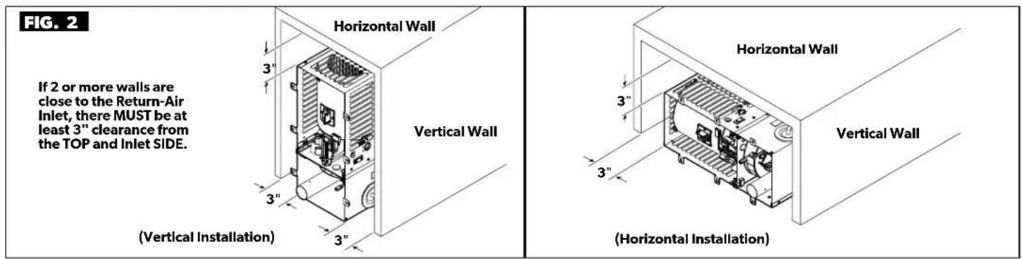
Proper Return-Air Inlet Clearance
⚠ WARNING When a furnace is installed so that supply ducts carry air circulated by the furnace to areas outside the space containing the furnace, the return air shall also be handled by duct(s) sealed to the furnace casing and terminating outside the space containing the furnace. Failure to do so could result in property damage, serious injury, or death.
NOTICE Furnaces MUST have at least the Minimum Return Air detailed in section "A. Model Specifications" on page 4 and page 5.

PRE-INSTALLATION
B. Determining A Door Installation Option And Cutout Sizing
- Determine whether the RV has a standard door, flush door, or small vent configuration.
- Cut an opening through the side wall to fit the door installation option.
Standard Door Installations

other
FIG. 1 | Door Cutout Type | Diameter (in inches) | | :--- | :--- | | Small Standard Door Cutout | 12.50 to 12.63 | | Medium Standard Door Cutout | 17.00 to 17.13 | | Large Standard Door Cutout | 17.00 to 17.13 | | FloorFloor | 9.25 to 9.38 |Flush Door Installations

other
| Floor Location | Width (ft) | | -------------- | ---------- | | Small Flush Door Cutout | 15.00 to 15.13" | | Medium Flush Door Cutout | 19.75 to 19.88" | | Large Flush Door Cutout | 19.75 to 19.88" | | Floor Floor | R 0.50" to 0.63" | | Width (R) | 15.00 to 15.13" | | Width (R) | 10.00 to 10.13" | | Width (R) | 19.75 to 19.88" | | Width (R) | 10.00 to 10.13" | | Width (R) | 12.00 to 12.13" | | Width (R) | R 0.50" to 0.63" |Small Vent Installations

- There is NO door cutout on the outside of the RV for the small vent installation. The cutout is a hole in the side of the RV used to vent the Furnace outside of the RV.
Access must be provided directly in front of the Furnace on the inside of the RV, for removal of the Furnace during servicing.
PRE-INSTALLATION
C. Ducting
⚠ WARNING Failure to obey the following warnings could result in property damage, serious injury, or death:
- Do NOT install floor registers within 24" of return-air openings.
- Do NOT use undersized ducting, which can cause high-temperature limiting.
- Do NOT use oversized ducting, which can cause inadequate air flow from the registers. When hard ducting is 1-1/2" in depth, additional flex ducts may be needed to maintain air flow requirements.
- Hard ducting MUST be sealed to the Furnace and the floor.
- Spacing of 1/4" to ducting, within 3' of the Furnace, must be provided unless UL-listed, wire-bound, vinyl ducts are used. All ducting material used must be rated for continuous use at a minimum of 200 °F.
• Floor registers must NOT be installed directly below the thermostat.
Setting Up The Return-Air Pathways

Keep all return-air passages clear to allow the Furnace to function properly. Make sure the total return-air opening size(s) meet the clearance requirements specified in "A. Model Specifications" on page 4 and page 5. Do NOT block the return airflow path with ducting.

Identifying Duct Locations


PRE-INSTALLATION
Air Discharge Configuration Examples
The following figures offer a visual representation of the detailed discharge requirements outlined in the "Air Discharge Requirements" tables on page 11 and page 12. These examples show vertical and horizontal installations, using different Furnace models and ducting options.

• Horizontal Furnace – Bottom exit into hard ducting

- Vertical Furnace – Bottom exit into hard ducting
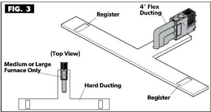
- 4" flex ducts into hard ducting

- Make sure to use at least the minimum number of 4" flex ducts required for your model size. See "Air Discharge Requirements" on page 11 and page 12.

For medium and large Furnaces: ducts 8 and 9 are used for additional ducting only, and are not used to calculate the required discharge area shown at the bottom of page 11.

- 5" ducting over 12" long must have an additional 4" duct added to the system.

To aid in the removal of the Furnace through the grill cutout for servicing, when using a front interior grill, orient the grill to the direction of the Furnace: horizontal if the Furnace is horizontal, vertical if the Furnace is vertical.
PRE-INSTALLATION
Air Discharge Requirements
| HORIZONTAL BOTTOM EXIT INTO HARD FLOOR DUCT | VERTICAL BOTTOM EXIT INTO HARD FLOOR DUCT | HORIZONTAL OR VERTICAL - USE DUCTS 3, 4 & 5 INTO HARD FLOOR DUCT | 4" FLEX DUCTS | 5" FRONT EXIT FLEX DUCTS | |
| DFL40 | Minimum CFM | ||||
| 220 175 165 215 N/A | |||||
| DISCHARGE REQ. | 4" x 10" Bottom exitPLUS1-4" flex duct (for hard ducting under 2.5" deep).Duct 6 or 7 is recommended. | 5" x 9-3/4" Bottom exit does not require additional ducts. | Horizontal or vertical.Use ducts 3, 4, and 5. | Three ductsMINIMUM.Four ducts recommended. | N/A |
| DFL35 | Minimum CFM | ||||
| 200 175 165 215 N/A | |||||
| DISCHARGE REQ. | 4" x 10" Bottom exitPLUS1-4" flex duct (for hard ducting under 2.5" deep).Duct 6 or 7 is recommended. | 5" x 9-3/4" Bottom exit does not require additional ducts. | Horizontal or vertical.Use ducts 3, 4,and 5. | Three ductsMINIMUM.Four ducts recommended. | N/A |
| HORIZONTAL BOTTOM EXIT INTO HARD FLOOR DUCT | VERTICAL BOTTOM EXIT INTO HARD FLOOR DUCT | HORIZONTAL OR VERTICAL - USE DUCTS 3, 4 & 5 INTO HARD FLOOR DUCT | 4" FLEX DUCTS | 5" FRONT EXIT FLEX DUCTS | |
| DFM35 | Minimum CFM | ||||
| 225 155 155 285 N/A | |||||
| DISCHARGE REQ. | 4" x 10" Bottom exitPLUS1-4" flex duct (for hard ducting under 2.5" deep).Duct 6 or 7 is recommended. | 5" x 9-3/4" Bottom exit does not require additional ducts. | Horizontal or vertical.Use ducts 3, 4,and 5. | Four ductsMINIMUM. | N/A |
| DFM30 | Minimum CFM | ||||
| 210 150 155 220 N/A | |||||
| DISCHARGE REQ. | 4" x 10" Bottom exitPLUS1-4" flex duct (for hard ducting under 2.5" deep).Duct 6 or 7 is recommended. | 5" x 9-3/4" Bottom exit does not require additional ducts. | Horizontal or vertical.Use ducts 3, 4 and 5. | Three ductsMINIMUM. | N/A |
| DFM25 | Minimum CFM | ||||
| 175 160 160 190 N/A | |||||
| DISCHARGE REQ. | 4" x 10" Bottom exit(40 in.2). | 5" x 9-3/4" Bottom exit does not require additional ducts. | Horizontal or vertical.Use ducts 3, 4 and 5. | Three ductsMINIMUM. | N/A |
| DFM20 | Minimum CFM | ||||
| 135 85 115 132 N/A | |||||
| DISCHARGE REQ. | 4" x 10" Bottom exit(40 in.2). | 5" x 9-3/4" Bottom exit does not require additional ducts. | Horizontal or vertical.Use any two ducts:3, 4 or 5. | Two ductsMINIMUM. | N/A |
| DFM16 | Minimum CFM | ||||
| 135 85 115 132 N/A | |||||
| DISCHARGE REQ. | 4" x 10" Bottom exit(40 in.2). | 5" x 9-3/4" Bottom exit does not require additional ducts. | Horizontal or verticalUse any two ducts:3, 4 or 5. | Two ductsMINIMUM. | N/A |
PRE-INSTALLATION
| HORIZONTAL OR VERTICAL USE (DUCTS 3, 4, & 5) OR BOTTOM EXIT INTO HARD FLOOR DUCT | 4" FLEX DUCTS | 5" FRONT EXIT FLEX DUCTS | |
| DFS20 | Minimum CFM | ||
| N/A | 130 92 | ||
| DISCHARGE REQ. | N/A | Two 4" flex ducts – one each from the left and right side, based on horizontal or vertical mounting. | One 5" OR two 4" ducts (5" can be reduced to 4" if necessary) |
| DFS16 | Minimum CFM | ||
| N/A | 110 82 | ||
| DISCHARGE REQ. | N/A | Two 4" flex ducts – one each from the left and right side, based on horizontal or vertical mounting. | One 5" OR two 4" ducts (5" can be reduced to 4" if necessary) |
| DFS12 | Minimum CFM | ||
| N/A | 90 80 | ||
| DISCHARGE REQ. | N/A | Two 4" flex ducts – one each from the left and right side, based on horizontal or vertical mounting. | One 5" OR two 4" ducts (5" can be reduced to 4" if necessary) |
| DFSA12 (LOW AMP) | Minimum CFM | ||
| N/A N/A | 60 | ||
| DISCHARGE REQ. | N/A N/A One 5" front duct ONLY | ||

Air flow: shown in cubic feet-per-minute, taken with a cold system (Cold CFM).
Registers: 4" x 10" floor registers flow air better than 4" Round Plastic registers. Using 4" Round registers may require additional ducting.
Required Discharge
| MODELS REQUIRED DISCHARGE AREA | ||
| SMALL | DFSA12 Front Grill or 15 in. | ^2 |
| DFS (12, 16, & 20) 24 in. | ^2 | |
| MEDIUM | DFM (16 & 20) 24 in. | ^2 with 4" flex |
| DFM (25 & 30) 36 in. | ^2 with 4" flex | |
| DFM35 48 in. | ^2 with 4" flex | |
| DFM (30 & 35) Horizontal Bottom 48 in. | ^2 (Bottom + 4" duct) | |
| DFM (16, 20, & 25) Horizontal Bottom | 40 in. ^2 (Bottom only) | |
| DFM Vertical Bottom | 48 in. ^2 (Bottom only) | |
| LARGE | DFL (35 & 40) | 36 in. ^2 with 4" flex |
| DFL (35 & 40) Horizontal Bottom | 48 in. ^2 (Bottom + 4" duct) | |
| DFL (35 & 40) Vertical Bottom | 48 in. ^2 (Bottom only) | |
Installing The Floor Discharge System

Read BEFORE proceeding:
- Each 4" duct opening provides 12 in. ^2 of discharge area. For each closeable register, provide an extra 12 in. ^2 of noncloseable duct discharge area. Make sure that all clearances and temperature requirements are met and the seal is airtight.
- Ducting into dead-air space with no return air, such as holding tank areas, does not count toward achieving minimum discharge requirements.
- 2" ducts exiting into the return-air space count as part of the minimum discharge area and minimum CFM.
- As applicable, the medium and large Furnace can be installed as a bottom-discharge system in either a horizontal or vertical position.

- Cut the opening for the floor discharge system in the floor of the RV.
- Standard Door: see "Standard Door Floor Discharge Installations" on page 14.
- Flush Door: see "Flush Door Floor Discharge Installations" on page 14.
-
Small Vent: see "Small Vent Floor Discharge Installations" on page 14.
-
Remove the bottom discharge plate or side.
- Fasten the plenum plate bend tabs over the floor cutout.
- Place the gasket on the plenum around the floor opening.

Plenum plates and gaskets are available for purchase through Dometic. If not using a Dometic gasket and plenum plate, seal the Furnace to the hard ducting system using an approved foil tape, or use a gasket that has a 300^ F minimum temperature rating and a UL94-V0 rating.
Vertical Mount Furnace: Kit 30205
Horizontal Mount Furnace: Kit 30261
PRE-INSTALLATION
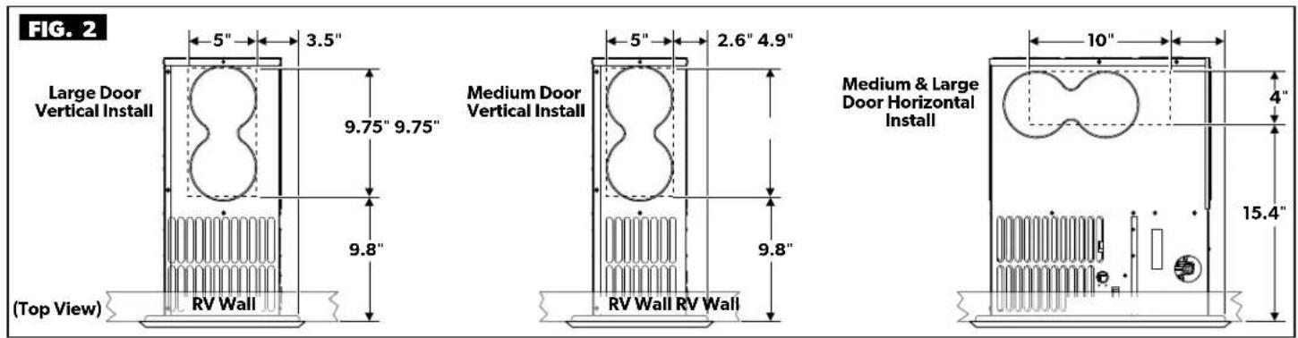
Standard Door Floor Discharge Installations

The dotted lines around the knockouts in the figures represent the floor-hole position.

Flush Door Floor Discharge Installations
Small Vent Floor Discharge Installations

PRE-INSTALLATION
Installing The Duct Adapters

- Remove the knockout plates from the desired outlets.
• Cover all unused knockouts.
If a knockout is removed accidentally, cover plates are available for purchase through Dometic.
Cover Plate: 31361

• Install the duct adapters (provided) by inserting the flange over the casing hole and turning the duct adapter 90° to lock the tab into the casing slot.
- Securely attach ducting to the duct adapter. If using screws to secure the ducting, do not use screws longer than 1/2" .
D. Installing the Furnace
- Proceed to the appropriate installation section to install the Furnace:
- Standard Door: See "A. Installing The Furnace Using A Standard Door Option" on page 16.
- Flush Door: See "B. Installing The Furnace Using A Flush Door Option" on page 17.
- Small Vent: See "C. Installing The Furnace Using The Small Vent Option" on page 18.
A. Installing The Furnace Using A Standard Door Option

The standard door option requires that the rectangular hole cut into the wall for the door opening has sharply cut corners to match the Furnace. The Furnace must be able to slide freely through the opening.
- Place the Furnace through the cutout approximately 1"-2" from the wall.
- Apply RTV sealant or butyl tape to the entire back flange of the bezel.

- Place the bezel over the tabs and flush with the front edge of the casing. Be sure the edge of the bezel marked "TOP" faces the top of the casing. Bend the casing tabs over the bezel.
- Push the Furnace and bezel against the side wall. Secure using six #6 or #8-18 Pan Head Type A screws (not provided) placed through the bent tabs, bezel, and into the RV wall.
- Place six more screws (three per side) to the left and right side of the bezel. The bezel MUST fit tightly against the wall. Remove excess sealant.
Do NOT deform the bezel during placement. The bezel must fit tightly to maintain an airtight seal.
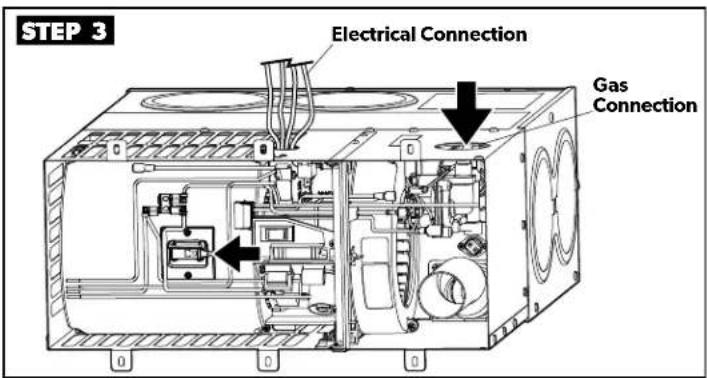
- Connect the electrical wiring. Refer to "H. Connecting The Electrical" on page 22.
- Connect the gas line to the valve. Refer to "F. Connecting The Gas" on page 20.

- Align the door with the bezel.
- Secure the door with four #6-19x1/2" thread-forming screws for plastic (not provided), or with a screw that engages the RV wall and that is longer than 1/2".
- Place the screws through the door into the bezel bosses.
- Insert the vent assembly (provided) through the hole in the door, making sure the vent assembly goes into the chamber tube. Make sure the vent assembly is aligned with the Dometic text at the TOP.
- Secure the vent assembly to the door using four stainless steel exhaust screws (provided with the door).
- To secure the Furnace to the floor of the RV, proceed to "D. Installing The Mounting Brackets" on page 19.
INSTALLATION
B. Installing The Furnace Using A Flush Door Option


Flush-mounted door systems require the Furnace to be installed on a 1" high platform, so the door cutout is level with the floor surface. Otherwise, the side wall must be routed out across the bottom to the depth of the bezel, to create a pocket area. The flush door option requires 1/2" radius corners.
- Place the Furnace through the cutout.
- Connect the electrical wiring. Refer to "H. Connecting The Electrical" on page 22.
- Connect the gas line to the valve. Refer to "F. Connecting The Gas" on page 20.

- Use three screws (not included) on each side of the Furnace to secure the flush mounting brackets to the wall. Leave 5/16" of space from the bracket to the outside of the wall.
- Apply RTV sealant or butyl tape to the back of the bezel and the back of the flanges on the recess pan, where it will overlap with the wall.
- Pull the front edge of the Furnace out of the wall approximately 2".

- Slide the recess pan over the Furnace and place the bezel on the six mounting tabs.
- Push the recess pan and bezel forward until the six casing tabs move through the slots in the bezel.
- Bend the casing tabs to the outside of the bezel.
- Align the top three holes on the bezel with the holes in the recess pan, then place six (three on the top and three on the bottom) #6 or #8 x1/2" Pan Head Type AB screws, or self-drilling screws, (not provided) into the top and bottom holes on the bezel. Tighten the screws to attach the bezel to the recess pan.
- Secure the Furnace using six (three per side) #6 or #8 x1/2" Pan Head Type AB screws, or self-drilling screws, (not provided) placed through the bezel, the recess pan, and into the flush mounting brackets. Remove excess sealant.

Do NOT deform the bezel during placement. The bezel must fit tightly to maintain an airtight seal.

- Secure the door using four #6-19x3/8" thread-forming screws for plastic (not provided). The door should be flush with the RV wall.
- Insert the vent assembly (provided) through the hole in the door, making sure the vent assembly goes into the chamber tube with the Dometic text aligned at the TOP.
- Secure the vent assembly to the door using four stainless steel exhaust screws (provided with the door).
- To secure the Furnace to the floor of the RV, proceed to "D. Installing The Mounting Brackets" on page 19.
C. Installing The Furnace Using The Small Vent Option
⚠ WARNING Failure to obey this warning could result in property damage, serious injury, or death:
-
Do NOT install vents where projection or door openings come within 6" of the vent opening. The RV door, panel, or cover material may discolor, warp, or burn from the exhaust temperature.
• CARBON MONOXIDE HAZARD: -
Properly seal the vent assembly to prevent carbon monoxide from entering the RV. Do NOT vent exhaust air or draw combustion air from the living area or an enclosed porch.
- Do NOT vent the Furnace with a venting system serving another appliance.
Access must be provided directly in front of the Furnace on the inside of the RV for removal of the Furnace during servicing.

- Locate the Furnace exhaust vent cutout location.
- Drill a 3-1/2" dia. hole through the wall for intake/exhaust.
The maximum exterior wall thickness is 2-1/2". Do NOT exceed maximum wall thickness. Purchase an optional vent kit to extend the vent to a 3" wall thickness, if necessary.

- Apply butyl tape or RTV sealant to the back flange of the vent extension before securing to the wall.
- Hold the vent extension with the printed "THIS SIDE UP" text at the top, and the water dam at the bottom.
- Push the vent extension into the wall until it slides onto the vent panel.
- Align the vent assembly (provided) over the vent extension so that the Dometic text is at the TOP.
- Push the vent assembly into the chamber tube and secure using four stainless steel exhaust screws (not provided).
i Overlap the vent tube over the chamber tube by a minimum of 1-1/2" for proper venting of exhaust fumes.
- Connect the electrical wiring. Refer to "H. Connecting The Electrical" on page 22.
- Connect the gas line to the valve. Refer to "F. Connecting The Gas" on page 20.
- Push the Furnace vent panel against the RV wall.
The Furnace vent panel MUST be pushed against the RV wall before installing the mounting brackets.
- Proceed to "D. Installing The Mounting Brackets" on page 19.
D. Installing The Mounting Brackets

- Make sure the mounting surface on the RV is flat and the Furnace is positioned evenly (front-to-back, side-to-side).
- Fasten the two mounting brackets (provided) to the casing by placing the brackets over any two of the three holes at the rear of the Furnace. Secure using two #8-18x1/2" screws (provided).
- Secure the Furnace mounting brackets to the RV using screws (not provided).
Mounting brackets can be attached to the Furnace casing by removing an existing casing screw, ONLY with prior approval from Dometic. When securing the Furnace, it MUST be accessible and easily removed for service.
E. Running the Ductwork

- Stretch out all of the ducts and run them directly to the outlets. Keep the number of angles to a minimum and avoid sharp bends, deep sags, or crushed ducts, as shown.
- Attach and secure the 4" flexible duct to the adapter(s).
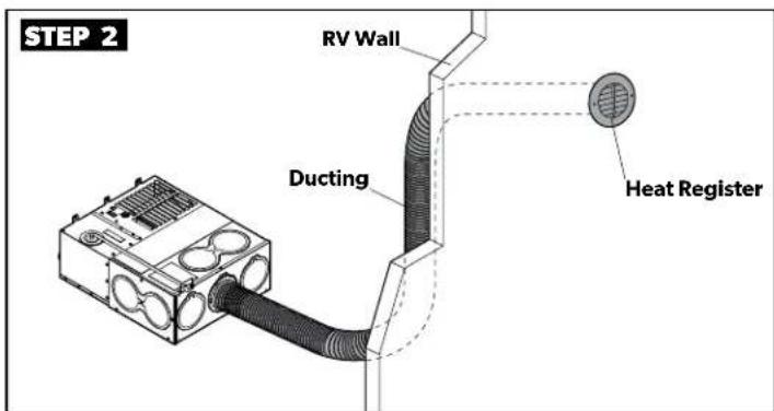
- Run duct(s) to the desired location(s) within the RV.
- Secure the ducting to the register(s).
If the burner cycles ON and OFF at the high-temperature limit, it may be due to a restriction or bend in the ductwork. Add extra ducting to correct this condition. - Adjust the Furnace to the proper temperature rise after installation of the Furnace and ducting is complete. The Furnace is tested to the temperature rise specified on the rating plate.
- If checking the temperature rise is not possible, measure the airflow at each register. Airflow should meet or exceed the measurements in the "Air Discharge Requirements" on page 11.
- Adjust the ducting installation to obtain an airflow rate total from all living area vents (in CFM) of the Furnace, as specified in the "Air Discharge Requirements" on page 11.
- If readings are below the table values, improve the airflow by adding ducts or reducing/eliminating system restrictions. Reference the "Air Discharge Configuration Examples" on page 10 for guidance.
F. Connecting The Gas
WARNING FIRE OR EXPLOSION HAZARD. Failure to obey the following warnings could result in property damage, serious injury, or death:
- Install gas connections in compliance with the applicable supplemental directives listed in this manual. Refer to "C. Supplemental Directives" on page 2.
- NEVER use an open flame to check for gas leaks. Use a commercially available soap solution made specifically for the detection of leaks to check all connections, as specified in these instructions.
- Should the gas supply fail to shut off or if overheating occurs, shut off the gas valve to the Furnace before shutting off the electrical supply.
- Do NOT put sealing compound on flare fittings.

An extended manifold is used in this example; however, the use of tubing or other variations to connect the gas is acceptable.
- Treat all male pipe threads, other than flare fittings, with a sealing compound resistant to a chemical reaction with LP gas.
- Remove the grommet plug from the Furnace and install on the gas line.
- Insert the gas line through the hole in the top of the casing.
- Connect the gas line to the fitting located on the valve. If the Furnace is supplied with an extended manifold, connect the gas line at the rear of the Furnace.
- Reinstall the grommet plug on the casing, as it is a required air seal. DO NOT CUT.
- Use two wrenches to hold the valve and flare nut, and tighten the flare nut over the gas line.
- Torque the fitting to 20–22 ft. Ibs. Do NOT twist the valve out of position when tightening the gas line.
For DFLA35 and DFLA40 models only, a gas conversion kit is included with your Furnace. To convert the Furnace gas type, proceed to "G. Converting The Furnace Gas Type" on page 21.
LP Gas Pressure Test
i Read BEFORE proceeding:
- Test all piping systems BEFORE connecting the Furnace.
- Disconnect the Furnace and any individual shut-off valves from the gas supply piping system when pressure testing the system at pressures of more than 1/2" PSI.
- If local codes allow the use of a flexible gas appliance connector, do NOT use a connector which has previously serviced another gas appliance.
-
For gas conversions only, a 1/8" NPT plug is provided upstream of the gas connections for checking the gas pressure.
-
Perform an air pressure test on the piping system. The test must maintain an air pressure of a least 6" of mercury or 3 PSI for at least 10 minutes.
- Adjust the piping system to maintain the minimum gas supply pressure listed on the rating plate, when all appliances are in operation.
- Test gas connections for leakage with a commercially available soap solution made specifically for the detection of leaks.
INSTALLATION
G. Converting The Furnace Gas Type
NOTICE This section applies to DFLA35 and DFLA40 models only. These models are set up for LP gas at the factory, but can be converted to natural gas. A natural gas conversion kit is included.
⚠ WARNING Any conversion to natural gas must conform with local codes, or in the absence of local codes, with the National Fuel Gas Code, ANSI Z223.1/NFPA 54 Natural Gas and Propane Installation Code, in addition to the Standard for Recreational Vehicles NFPA1192 and CSA Z240 RV Recreational Vehicle Code.
Changing The Adjustment Regulator Caps

Read the following BEFORE proceeding:
- The convertible valve is set for a pressure setting of 3.5" for natural gas (NAT) and 10.5" for LP gas. These settings are not adjustable.
- Do NOT modify the adjustment regulator caps or use them with any other valve.
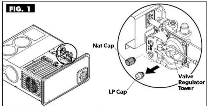
- Unscrew the adjustment regulator cap and remove from the valve regulator tower. Do NOT remove the rod from inside the regulator tower or perform any adjustments.
- Place the NAT or LP cap appropriate for the conversion onto the valve regulator tower.
- Tighten the adjustment regulator cap by hand or use a small wrench. Do NOT overtighten the adjustment regulator cap.
- Install the main burner orifice. Refer to the "Conversion Specifications Table" for information specific to LP or NAT conversion.
Conversion Specifications Table
| GAS TYPE | BTU/HR | LINE PRESSURE | REGULATOR CAP SETTING | DRILL SIZE |
| Propane (LP) | 40,000 | 11" WC | 10.5" WC | 49P |
| Natural (NAT) | 40,000 | 7" WC | 3.5" WC | #30 |
| Propane (LP) | 35,000 | 11" WC | 10.5" WC | #51 |
| Natural (NAT) | 35,000 | 7" WC | 3.5" WC | #30 |
WC = Water Column
Replacing The Orifice

Read the following BEFORE proceeding:
• Each Furnace is supplied with two main burner orifices. One is installed on the manifold and the other is attached to the blower housing cover.
- The type of gas in use must match the adjustment regulator cap and orifice installed in the Furnace.

- Disconnect the gas line from the valve.
- Remove the three screws holding the burner assembly to the back wall of the control box.
- Remove the two screws holding the burner to the manifold.
- Unscrew the orifice using a 7/16" wrench or socket.
- Use the "Conversion Specifications Table" to select the correct orifice needed for the gas type.
• Install the new orifice. - Reverse steps 1–3 to reinstall the burner, burner assembly, and the gas line.
- Test gas connections for leakage with a commercially available soap solution made specifically for the detection of leaks.
- Place the "converted" sticker (provided) in a visible location, next to the model number label.
H. Connecting The Electrical
⚠ WARNING ELECTRICAL SHOCK HAZARD. Failure to obey the following warnings could result in property damage, serious injury, or death:
- The Furnace must be electrically grounded in accordance with local codes, or in the absence of local codes, with the National Electrical Code, ANSI/NFPA 70, and/or the Canadian Electrical Code, CSA C22.1, Part 1, if an external electrical source is utilized.
- The Furnace MUST be installed so that electrical components are protected from water and other installation debris.
- If the Furnace model is designed for negative ground 12 VDC only, do NOT attempt to alter Furnace for a positive ground system or connect a 12 VDC Furnace to 120 VAC or 240 VAC. Furnaces with 12 VDC connection are for low-voltage battery or direct current only.
- Do NOT "Hi Pot" the Furnace unless the electronic ignition system (circuit board) has been disconnected.
- Do NOT use a battery charger to supply power to a DC model Furnace even when testing.
- Do NOT use 120 VAC current with VDC models. Do NOT use 12 VDC current with 120 VAC models.
- The direct high voltage spark ignition of the Furnace generates a radio frequency that may cause interference with other microprocessor-based equipment. Locate any equipment at least five feet from the Furnace location.
Overcurrent Protection (No Wire Bundling Restrictions)
| WIRE SIZE AMPACITY WIRE TYPE | ||
| 20 3 Stranded Only | ||
| 18 6 Stranded Only | ||
| 16 8 Stranded Only | ||
| 14 15 Stranded Only | ||
| 12 20 | Stranded Only | |
| 10 30 | Stranded Only | |
| 8 40 | Stranded Only | |
| 6 55 | Stranded Only | |
| 4 75 | Stranded Only | |
| 2 100 | Stranded Only | |
Wiring Information
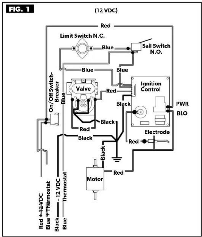
- To route wiring to the Furnace refer to the "Wiring Diagrams" on page 23.
- Use the smallest wire size shown in the table to minimize voltage drop.
- If power is supplied from a converter that is equipped with a charging port, wire the converter to the Furnace at the same time as the battery.
- If a Furnace is supplied with a connector block on the field connections, use the mating parts.
- All Furnaces have a power switch to turn the Furnace off for servicing. Confirm the switch is in the ON position.
Additional Information For VAC Wiring Only
- Furnaces equipped with 120 VAC motors use power from a 24 VAC transformer inside the Furnace to power electrical component parts.
- The power switch for VAC Furnaces is located in the valve circuit leg only.
- Use a minimum of 18 GA wire to route 120 VAC and thermostat leads to wires located on the left side of the control box.
Overcurrent Protection
| AWG OR SAE CONDUCTOR SIZE | MAXIMUM AMPACITY AT CONDUCTOR INSULATION TEMPERATURE RATING OF 90° | MAXIMUM AMPACITY AT CONDUCTOR INSULATION TEMPERATURE RATING OF 105 °C/ 125 °C |
| 20* | 5 | 7.5 |
| 18* | 7.5 | 10 |
| 16* | 10 | 15 |
| 14* | 17.5 | 20 |
| 12* | 22.5 | 25 |
| 10** | 40 | 50 |
| 8** 55 | 70 | |
| 6** | 75 | 100 |
| 4** 95 | 120 | |
| 2** | 130 | 150 |
| 1** | 150 | - |
| 1/0** | 170 | - |
| 2/0** | 195 | - |
| 3/0** | 225 | - |
| 4/0** | 260 | - |
* Not more than seven wires per harness; **Not more than three wires per harness
A 15-amp circuit breaker is provided with the DFMD35, DFLD35, and DFLD40 Furnace models. Install the breaker inside the main fuse panel in place of a normal fuse for the RV. Place the circuit breaker in the "Furnace Only Circuit".
INSTALLATION
Wiring Diagrams


INSTALLATION
I. Installing The Thermostat
⚠ WARNING Do NOT install the thermostat where there are other heating loads, such as direct sunlight, heat-producing appliances (television, radio, wall lamp, etc.) Furnace, or air conditioner output registers. Failure to follow these instructions could result in serious injury or death.

Read BEFORE proceeding:
- Wire the thermostat using 22 AWG minimum stranded wire.
• Purchase a thermostat rated for 12 VDC or 24 VAC, Minimum 1 AMP rating.
- Disconnect all electrical power to the Furnace.
- Locate a dry area away from the heat registers with good air circulation for the thermostat installation.
- Place the thermostat 48"-54" above the main living area floor on an INTERIOR wall, when possible.
- Use a 3/4" spacer between the thermostat and wall, for proper room air sensing when placing on an EXTERIOR wall.
- Follow manufacturer's installation instructions provided with the thermostat.
TESTING
A. Testing The Furnace
WARNING
Do NOT operate the Furnace while the vehicle is in motion or being towed.

Testing The Operation
- Turn the manual valve (if equipped) or the valve at the outside LP tank to the OFF position. Do NOT force.
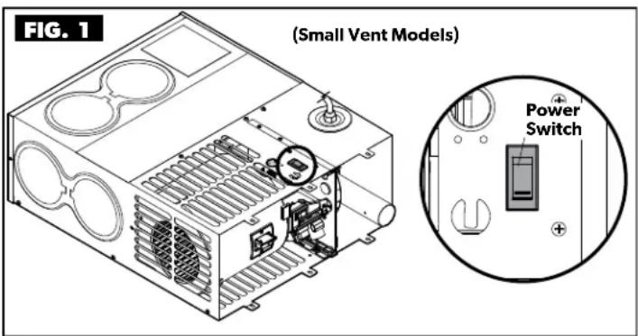
This Furnace is equipped with a power switch. Gas will not flow to the burner, and the Furnace will not operate with the power switch in the OFF position. -
Turn the power switch to the ON position.
This Furnace is equipped with an ignition device which automatically lights the burner. Do NOT light the burner by hand. -
Set the thermostat above room temperature to begin blower operation. A slight delay will occur before the blower begins running.
-
Allow the blower to run for 15 seconds to complete the combustion chamber purge cycle.
- If the blower does not come on or stops before the ignition cycle, shut down the Furnace and contact your dealer or a local RV service agency.
-
Move the thermostat lever below room temperature.
-
Wait approximately 90 seconds for the blower to stop running.
-
Open the manual shut off valve (if equipped) or the valve at the LP tank. Correct Furnace operation depends on the valve being fully open. Never attempt to operate with a valve partially closed.
-
Turn the shut off switch to the ON position.
-
Set the thermostat lever to the desired setting. If set above room temperature, the blower begins running.
-
Allow 15 seconds for the main burner to light after the blower begins running.
- If the burner does not light, confirm the gas is ON and repeat steps by resetting the thermostat to purge any air in the gas system.
- If after three attempts there is no ignition, shut down the Furnace and contact your dealer or a local recreational vehicle service agency. Do NOT continue to cycle the Furnace through the thermostat in an attempt to get ignition.
Shutting Down The Furnace
- Set the thermostat to the lowest setting, then turn to the OFF position.
- Turn the manual shut off valve at the LP tank (if equipped) to the OFF position. Do NOT force the valve.
- At the exterior access panel, turn the valve shut-off switch to the OFF position.
DIAGNOSTICS
A. Ignition Control Diagnostic Codes
- The following chart gives the diagnostic codes given by the ignition control when faults are present. An LED light, located in the middle of the control board, will flash the codes indicated in the diagnostic chart. There is a standard of three tries for ignition controls.
- A "soft lockout" is a condition that is timed and will make additional attempts to correct the problem.
- A "hard lockout" requires resetting the thermostat or turning the power switch off, and then back on.
DIAGNOSTIC CHART
| FAULT LED INDICATION LOCKOUT | |
| Internal Circuit Board Failure Steady On, No Flashing Hard | |
| Limit Switch/Airflow Problems 1 Flash With 3-Second Pause Soft | |
| Flame Sense Fault 2 Flashes With 3-Second Pause Hard | |
| Ignition Lockout Fault 3 Flashes With 3-Second Pause Soft (1 hour retry) |
TROUBLESHOOTING
| ISSUE | SOLUTION |
| Furnace will not light – Blower does not turn on. | 1. Check the main fuse panel for a blown fuse.2. The Furnace-installed breaker switch may be tripped or OFF – Contact a trained RV service provider.3. The 12 VDC power is low; check the RV system voltage.4. The Furnace may be in lockout. Reset the Furnace by switching the thermostat to OFF for 10 seconds, then switch the thermostat to ON. If air is in the propane line, repeat this process up to three times.5. Check the intake and vents to make sure they are not blocked or obstructed. |
| Furnace will not light – Blower does turn on. | 1. Air is in the propane line. Purge the air by turning on other appliances (like a cooktop) that are further downstream from the propane tanks.2. The thermostat is not set to Heat or a high enough temperature. Adjust the thermostat. |
| Furnace shuts off before it reaches the desired temperature. | 1. Check to make sure all the vents are open and not covered.2. Check the air intake to make sure it is not blocked or obstructed. |
REPLACEMENT PARTS
WARNING ELECTRICAL SHOCK, FIRE, EXPLOSION AND/OR CARBON MONOXIDE HAZARD. Use only Dometic replacement parts and components, which are specifically approved for use with the Furnace. Failure to obey this warning could result in dangerous operation, property damage, serious injury, or death:
- For replacement part information, see the DF Series Furnace Parts List. For the most current information, visit www.eDometic.com.
dometic.com
YOUR LOCAL DEALER
dometic.com/dealer
YOUR LOCAL SUPPORT
dometic.com/contact
dometic.com/sales-offices

- INTRODUCTION
- IMPORTANT SAFETY INSTRUCTIONS AND DOCUMENT SYMBOLS
- Recognize Safety Information
- Understand Signal Words
- Supplemental Directives
- U.S.A.
- CANADA
- FOR DFLA35 and DFLA40 Models Only
- General Safety Messages
- GENERAL INFORMATION
- Model Specifications
- Model Dimensions
- Identifying The Furnace Location
- ⚠ WARNING Failure to obey the following warnings could result in property damage, serious injury, or death:
- Determining The Installation Type And Clearances Required
- Minimum Clearance To Combustibles
- PRE-INSTALLATION
- Proper Return-Air Inlet Clearance
- Determining A Door Installation Option And Cutout Sizing
- Ducting
- Setting Up The Return-Air Pathways
- Air Discharge Configuration Examples
- Installing The Floor Discharge System
- Read BEFORE proceeding:
- Standard Door Floor Discharge Installations
- Installing The Duct Adapters
- Installing the Furnace
- Installing The Furnace Using A Standard Door Option
- INSTALLATION
- Installing The Furnace Using A Flush Door Option
- Installing The Furnace Using The Small Vent Option
- ⚠ WARNING Failure to obey this warning could result in property damage, serious injury, or death:
- Installing The Mounting Brackets
- Running the Ductwork
- Connecting The Gas
- LP Gas Pressure Test
- Converting The Furnace Gas Type
- Changing The Adjustment Regulator Caps
- Replacing The Orifice
- Connecting The Electrical
- ⚠ WARNING ELECTRICAL SHOCK HAZARD. Failure to obey the following warnings could result in property damage, serious injury, or death:
- Wiring Information
- Additional Information For VAC Wiring Only
- Installing The Thermostat
- TESTING
- Testing The Furnace
- Testing The Operation
- Shutting Down The Furnace
- DIAGNOSTICS
- Ignition Control Diagnostic Codes
- REPLACEMENT PARTS
Brand : DOMETIC
Model : DFLA 35211
Category : Heating