
CLXI-4IND - Uncategorized Crestron - Free user manual and instructions
Find the device manual for free CLXI-4IND Crestron in PDF.


| Product Type | Switcher / Interface |
| Brand | Crestron |
| Model | CLXI-4IND |
| Dimensions (W x H x D) | 4.6 x 2.4 x 1.2 inches |
| Weight | 0.5 lb (approx.) |
| Power Supply | PoE (Power over Ethernet) |
| Input Ports | 4 x HDMI |
| Output Ports | 1 x HDMI |
| Supported Resolutions | Up to 4K @ 60Hz |
| Control Options | RS-232, IR, Ethernet |
| Rackmountable | Yes (with optional kit) |
| Operating Temperature | 32 to 104 °F |
| Mounting | Surface or rack mount |
| Compliance | FCC, CE, RoHS |
| Package Contents | Device, mounting screws, quick start guide |
| Warranty | 3 years limited |
| Cleaning Instructions | Wipe with dry, soft cloth |
| Safety | Use only with approved PoE injectors |
| Support | Contact Crestron dealer or online support |
Frequently Asked Questions - CLXI-4IND Crestron
User questions about CLXI-4IND Crestron
0 question about this device. Answer the ones you know or ask your own.
Ask a new question about this device
Download the instructions for your Uncategorized in PDF format for free! Find your manual CLXI-4IND - Crestron and take your electronic device back in hand. On this page are published all the documents necessary for the use of your device. CLXI-4IND by Crestron.
USER MANUAL CLXI-4IND Crestron
The CLTI/CLXI-2IND is a 2-inductor terminal block and module kit while the CLTI/CLXI-4IND is a 4-inductor terminal block and module kit. Inductor modules are typically used to reduce hum from incandescent lamps that are connected to dimmer modules in a Crestron lighting system. These kits can be mounted in any Crestron Automation Enclosure (CAEN or CAENIB-Series Enclosures). The terminal block is for connecting wires into and out of the inductor module. The inductor is wired in series between the output of the dimmer module and the load. The maximum load for any inductor in the module is 10 amps.
Each of these Terminal Block and Module kits is considered single entities and must be used together. The terminal blocks (CLTI-2IND and/or CLTI-4IND) are shipped separately from their respective modules (CLXI-2IND and CLXI-4IND) to permit termination of the field wiring to the terminal block prior to installation of the module, as described in this guide.
CLXI-2IND and CLXI-4IND modules can also be connected to CLTIBN-2IND and CLTIBN-4IND terminal blocks. For installation information, refer to the latest version of the CLTIBN Installation Guide (Doc. 6561) which is available for download from the Crestron website (www.crestron.com/manuals).
Installation
The terminal block and module must be mounted into a Crestron Automation Enclosure by a licensed electrician, in accordance with all national and local codes.
CAUTION: This equipment is for indoor use only. Mount in a well-ventilated area. The ambient temperature must be 0^ C to 40^ C ( 32^ F to 104^ F). The relative humidity must be 10% to 90% (non-condensing).
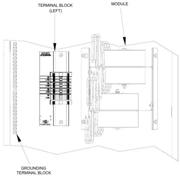
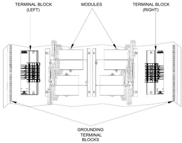
Terminal blocks are installed along the left side of single-wide enclosures and along the outside edges (left and right sides) of double-wide enclosures. Modules are installed along the right side of single-wide enclosures and side-by-side in the center of double-wide enclosures. When installing modules and terminal blocks in a double-wide enclosure, be sure to invert units on the right side so that they can be properly wired. Refer to the illustrations shown in the next column when considering the location of terminal blocks and modules within an enclosure.
NOTE: Inductor modules and terminal blocks should be installed above the dimmer modules, towards the top of the CAEN or CAENIB enclosure.
Terminal Block & Module Locations in Single-wide Enclosure (CLTI/CLXI-4IND shown)
Terminal Block & Module Locations in Double-wide Enclosure (CLTI/CLXI-4IND shown)
Installation and Field Wiring
NOTE: If CLTIBN terminal blocks are to be used, refer to the latest version of the CLTIBN Installation Guide (Doc. 6561).
NOTE: Both left-side and right-side adhesive wiring labels are provided. The left-side labels are used in both single and double-wide enclosures. The right-side labels are only used in double-wide enclosures.
- Remove the backing from the left or right adhesive wiring label.
- Apply the adhesive label by aligning the holes in the label with the holes on the Crestron Automation Enclosure where the terminal block is to be mounted. The wiring label lies beneath the terminal block as shown in the two wiring diagrams on this page.
- Use the two supplied self-tapping pan Phillips screws (8B x 14 length (6mm)) to secure the terminal block to the Crestron Automation Enclosure.
CAUTION: Bypass jumpers are provided to allow testing of circuits and to protect the module during installation. When properly secured by two screws, each of the two jumpers on terminal block shorts the dimmer output to the load so that the circuit is energized. Do not remove any bypass jumpers until all dimmer and load wiring has been completed, the circuit has been tested for electrical faults, and the module has been installed. Refer to “Module Installation” on next page.
NOTE: Use copper conductors only – rated 75^ C
- With the circuit breaker turned off, connect the dimmer module output (IN) and the load (OUT) wires to the IND terminal block per the markings provided on the wiring label (as shown in the following diagrams). Terminal blocks accept one 2.5 - 6.0 mm ^2 wire. Wires should be stripped to 12 mm. Tighten terminal blocks to 1 Nm.
- Test the circuit for electrical faults by turning on the circuit breaker and checking that the breaker does not trip and that the proper lighting loads are energized.
Wiring CLTI-2IND Terminal Block to the Feed and Load(s) for Single-Wide Enclosure and Left Side of Double-Wide Enclosure
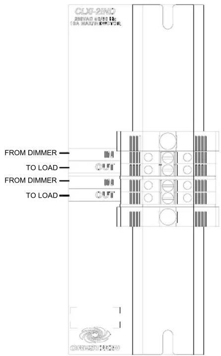
Wiring CLTI-2IND Terminal Block to the Feed and Load(s) for Right Side of Double-Wide Enclosure

Wiring CLTI-4IND Terminal Block to the Feed and Load(s) for Single-Wide Enclosure and Left Side of Double-Wide Enclosure

Wiring CLTI-4IND Terminal Block to the Feed and Load(s) for Right Side of Double-Wide Enclosure
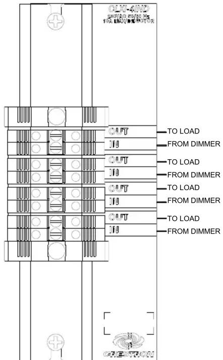
Module Installation
NOTE: Modules are to be installed after enclosure has been completely wired. Refer to the terminal block installation procedure on page 2 for details.
- Use the four supplied self-tapping screws (8B x 14 length (6 mm)) to secure the module to the enclosure.
- As shown in the following wiring diagrams, connect the wires from the module to the terminal block. Wires are pre-stripped to 12 mm. Tighten to 1 Nm.
NOTE: Each inductor should be wired with one wire connected to an input and the other wire connected to the corresponding output. The inductors have no polarity.
- Turn off the circuit breaker and remove the bypass jumpers on the terminal block. Refer to following diagrams for a close-up of the jumpers.
Wiring Diagram of the Terminal Block to the Inductor Module in a Single-wide Enclosure or the Left Side of a Double-wide Enclosure (CLTI/CLXI-2IND shown)
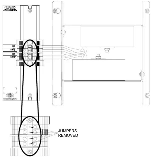
Wiring Diagram of the Terminal Block to the Inductor Module, in the Right Side of a Double-wide Enclosure (CLTI/CLXI-4IND shown)

Further Inquiries
If you cannot locate specific information or have questions after reviewing this guide, please take advantage of Crestron's award winning customer service team by calling the Crestron corporate headquarters at 1-888-CRESTRON [1-888-273-7876]. For assistance in your local time zone, refer to the Crestron website (http://www.crestron.com/offices) for a listing of Crestron worldwide offices.
You can also log onto the online help section of the Crestron website (http://www.crestron.com/onlinehelp) to ask questions about Crestron products. First-time users will need to establish a user account to fully benefit from all available features.
Return and Warranty Policies
Merchandise Returns / Repair Service
- No merchandise may be returned for credit, exchange or service without prior authorization from CRESTRON. To obtain warranty service for CRESTRON products, contact an authorized CRESTRON dealer. Only authorized CRESTRON dealers may contact the factory and request an RMA (Return Merchandise Authorization) number. Enclose a note specifying the nature of the problem, name and phone number of contact person, RMA number and return address.
- Products may be returned for credit, exchange or service with a CRESTRON Return Merchandise Authorization (RMA) number. Authorized returns must be shipped freight prepaid to CRESTRON, 6 Volvo Drive, Rockleigh, N.J. or its authorized subsidiaries, with RMA number clearly marked on the outside of all cartons. Shipments arriving freight collect or without an RMA number shall be subject to refusal. CRESTRON reserves the right in its sole and absolute discretion to charge a 15% restocking fee plus shipping costs on any products returned with an RMA.
- Return freight charges following repair of items under warranty shall be paid by CRESTRON, shipping by standard ground carrier. In the event repairs are found to be non-warranty, return freight costs shall be paid by the purchaser.
CRESTRON Limited Warranty
CRESTRON ELECTRONICS, Inc. warrants its products to be free from manufacturing defects in materials and workmanship under normal use for a period of three (3) years from the date of purchase from CRESTRON, with the following exceptions: disk drives and any other moving or rotating mechanical parts, pan/tilt heads and power supplies are covered for a period of one (1) year; touchscreen display and overlay components are covered for 90 days; batteries and incandescent lamps are not covered.
This warranty extends to products purchased directly from CRESTRON or an authorized CRESTRON dealer. Purchasers should inquire of the dealer regarding the nature and extent of the dealer's warranty, if any.
CRESTRON shall not be liable to honor the terms of this warranty if the product has been used in any application other than that for which it was intended or if it has been subjected to misuse, accidental damage, modification or improper installation procedures. Furthermore, this warranty does not cover any product that has had the serial number altered, defaced or removed.
This warranty shall be the sole and exclusive remedy to the original purchaser. In no event shall CRESTRON be liable for incidental or consequential damages of any kind (property or economic damages inclusive) arising from the sale or use of this equipment. CRESTRON is not liable for any claim made by a third party or made by the purchaser for a third party.
CRESTRON shall, at its option, repair or replace any product found defective, without charge for parts or labor. Repaired or replaced equipment and parts supplied under this warranty shall be covered only by the unexpired portion of the warranty.
Except as expressly set forth in this warranty, CRESTRON makes no other warranties, expressed or implied, nor authorizes any other party to offer any warranty, including any implied warranties of merchantability or fitness for a particular purpose. Any implied warranties that may be imposed by law are limited to the terms of this limited warranty. This warranty statement supersedes all previous warranties.
Trademark Information
All brand names, product names, and trademarks are the sole property of their respective owners. Windows is a registered trademark of Microsoft Corporation. Windows95/98/Me/XP/Vista and WindowsNT/2000 are trademarks of Microsoft Corporation.
Brand : Crestron
Model : CLXI-4IND
Category : Uncategorized