
HBG-100-48B - LED Controller Mean Well - Free user manual and instructions
Find the device manual for free HBG-100-48B Mean Well in PDF.


| Product Type | LED Controller (Constant Voltage) |
| Model | HBG-100-48B |
| Brand | Mean Well |
| Input Voltage | 90 ~ 305 VAC (47~63 Hz) |
| Output Voltage | 48 VDC |
| Output Current | 2.1 A |
| Output Power | 100.8 W |
| Efficiency | Up to 90% |
| Dimensions (L x W x H) | 227 x 68 x 38.8 mm |
| Net Weight | 0.8 kg |
| IP Rating | IP65 |
| Cooling | Free air convection |
| Operating Temperature | -40°C ~ +70°C |
| Safety Standards | UL, CUL, TUV, CE, ENEC, EAC |
| Protection Functions | Short circuit, over load, over voltage, over temperature |
| Dimming | 3-in-1 dimming (PWM, 0-10V, resistance) |
| Warranty | 5 years |
| Maintenance | Keep clean, ensure ventilation, check connections periodically |
| Cleaning | Wipe with dry cloth, avoid solvents |
| Mounting | Indoor or outdoor with proper enclosure, mounting holes provided |
Frequently Asked Questions - HBG-100-48B Mean Well
User questions about HBG-100-48B Mean Well
0 question about this device. Answer the ones you know or ask your own.
Ask a new question about this device
Download the instructions for your LED Controller in PDF format for free! Find your manual HBG-100-48B - Mean Well and take your electronic device back in hand. On this page are published all the documents necessary for the use of your device. HBG-100-48B by Mean Well.
USER MANUAL HBG-100-48B Mean Well
natural_image
Black industrial transformer with exposed wiring and terminal block (no text or symbols visible)


SELV
IP65 IP67
(CCC optional)


(for 36A,48A,60A only)


EAC CB CE UK CA
Features
- Constant Current mode output
• Circular metal housing with class design I
• Built-in active PFC function
• IP67 / IP65 rating for indoor or outdoor installations - Function options: output adjustable via potentiometer; 3 in 1 dimming; DALI
• Typical lifetime>50000 hours - 5 years warranty
Applications
• LED bay lighting
- LED stage lighting
- LED spot lighting
- Type "HL" for use in Class I, Division 2 hazardous (Classified) location.
GTIN CODE
MW Search: https://www.meanwell.com/serviceGTIN.aspx
■ Description
HBG-100 series is a 100W AC/DC LED driver featuring the circular shape design. It operates from 90\~305VAC and offers the constant current output models with different rated voltage between 24V and 60V. Thanks to the high efficiency up to 91.5%, with the fanless design, the entire series is able to operate for -40°C \~ +85°C case temperature under free air convection. The design of metal housing and IP67/IP65 ingress protection level allows this series to fit both indoor and outdoor applications. HBG-100 is equipped with various function options, such as dimming methodologies, so as to provide the optimal design flexibility for LED lighting system.
■ Model Encoding
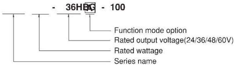
| Type | IP Level | Function Note | |
| Blank | IP67 | Io fixed. | In Stock |
| A | IP65 | Io adjustable through built-in potentiometer. | In Stock |
| B | IP67 | 3 in 1 dimming function (1~10Vdc, 10V PWM signal and resistance) | In Stock |
| AB | IP65 | Io adjustable through built-in potentiometer with 3 in 1 dimming function | In Stock |
| DA IP67 | DALI control technology. | In Stock | |
SPECIFICATION
| MODEL | HBG-100-24 | HBG-100-36 | HBG-100-48 | HBG-100-60 | |
| OUTPUT | RATED CURRENT | 4A | 2.7A | 2A | 1.6A |
| RATED POWER | 96W | 97.2W | 96W | 96W | |
| CONSTANT CURRENT REGION Note.2 | 14.4 ~ 24V | 21.6 ~ 36V | 28.8 ~ 48V | 36 ~ 60V | |
| OPEN CIRCUIT VOLTAGE(max.) | 25V | 37V | 49V | 62V | |
| CURRENT ADJ. RANGE | Adjustable for A/AB-Type (via built-in potentiometer) | ||||
| 2.4 ~ 4A | 1.62 ~ 2.7A | 1.2 ~ 2A | 1.0 ~ 1.6A | ||
| CURRENT RIPPLE | 5.0% max. @rated current | ||||
| CURRENT TOLERANCE | ±5.0% | ||||
| SETUP TIME Note.4 | 2000ms / 115VAC 500ms / 230VAC | ||||
| INPUT | VOLTAGE RANGE Note.3 | 90 ~ 305VAC 127 ~ 431VDC(Please refer to "STATIC CHARACTERISTIC" section) | |||
| FREQUENCY RANGE | 47 ~ 63Hz | ||||
| POWER FACTOR | PF>0.96/115VAC, PF>0.96/230VAC, PF>0.94/277VAC@full load(Please refer to "POWER FACTOR (PF) CHARACTERISTIC" section) | ||||
| TOTAL HARMONIC DISTORTION | THD< 20%(@load≥60%/115VC,230VAC; @load≥75%/277VAC)(Please refer to "TOTAL HARMONIC DISTORTION(THD)" section) | ||||
| EFFICIENCY (Typ.) Note.5 | 90.5% | 91% | 91% | 91.5% | |
| AC CURRENT (Typ.) | 1.1A / 115VAC 0.5A / 230VAC 0.45A / 277VAC | ||||
| INRUSH CURRENT (Typ.) | COLD START 60A(width=550μs measured at 50% lpeak) at 230VAC; Per NEMA 410 | ||||
| MAX. No. of PSUs on 16A CIRCUIT BREAKER | 4 units (circuit breaker of type B) / 8 units (circuit breaker of type C) at 230VAC | ||||
| LEAKAGE CURRENT | <0.75mA / 277VAC | ||||
| NO LOAD / STANDBY POWER CONSUMPTION | Standby power consumption <0.5W for B/AB/DA-TypeBlank/A-Type please refer to Note. 7 | ||||
| PROTECTION | OVER CURRENT | 95 ~ 108% | |||
| Constant current limiting | |||||
| OVER VOLTAGE | 28 ~ 35V | 41 ~ 49V | 54 ~ 63V | 65 ~ 75V | |
| Shut down o/p voltage re-power on to recovery | |||||
| OVER TEMPERATURE | Shut down o/p voltage re-power on to recovery | ||||
| ENVIRONMENT | WORKING TEMP. | Tcase=-40 ~ +85°C (Please refer to "OUTPUT LOAD vs TEMPERATURE" section) | |||
| MAX. CASE TEMP. | Tcase=+85°C | ||||
| WORKING HUMIDITY | 20 ~ 95% RH non-condensing | ||||
| STORAGE TEMP., HUMIDITY | -40 ~ +80°C, 10 ~ 95% RH | ||||
| TEMP. COEFFICIENT | ±0.03%/°C (0 ~ 50°C) | ||||
| VIBRATION | 10 ~ 500Hz, 5G 12min./1cycle, period for 72min. each along X, Y, Z axes | ||||
| SAFETY & EMC | SAFETY STANDARDS | UL8750(type*HL).CSA C22.2 No.250.13-12, ENEC BS EN/EN61347-1,BS EN/EN61347-2-13 independent, BS EN/EN62384:GB19510.1,GB19510.14, BIS IS15885(for 36A,48A,60A only), IP65 or IP67 approved EAC TP TC 004, | |||
| DALI STANDARDS | Compliance to IEC62386-101, 102, 207 for DA-Type only | ||||
| WITHSTAND VOLTAGE | I/P-O/P:3.75KVAC I/P-FG:2KVAC O/P-FG:0.5KVAC | ||||
| ISOLATION RESISTANCE | I/P-O/P, I/P-FG, O/P-FG:100M Ohms / 500VDC / 25°C / 70% RH | ||||
| EMC EMISSION Note.7 | Compliance to BS EN/EN55015, BS EN/EN61000-3-2 Class C (@load≥60%); BS EN/EN61000-3-3,GB17743 and GB17625.1, EAC TP TC 020 | ||||
| EMC IMMUNITY | Compliance to BS EN/EN61000-4-2,3,4,5,6,8,11, BS EN/EN61547,light industry level (surge immunity:Line-Earth:4KV,Line-Line:2KV), EAC TP TC 020 | ||||
| MTBF | 2433.4K hrs min. Telcordia SR-332 (Bellcore);299.3K hrs min. MIL-HDBK-217F (25°C) | ||||
| DIMENSIONOTHERS | ∅ 130mm *66.5mm (D * H) | ||||
| PACKING | 1.18Kg; 12pcs/15.7Kg/1.43CUFT(Blank/A/B Type),1.89CUFT(E Type) | ||||
| NOTE | 1. All parameters NOT specially mentioned are measured at 230VAC input, rated current and 25°C of ambient temperature.2. Please refer to "DRIVING METHODS OF LED MODULE".3. De-rating may be needed under low input voltages. Please refer to "STATIC CHARACTERISTIC" sections for details.4. Length of set up time is measured at cold first start. Turning ON/OFF the driver may lead to increase of the set up time.5. The DA type power supply is less efficient than the typical efficiency in specification by 1%.6. The driver is considered as a component that will be operated in combination with final equipment. Since EMC performance will be affected by the complete installation, the final equipment manufacturers must re-qualify EMC Directive on the complete installation again.7. To fulfill requirements of the latest ErP regulation for lighting fixtures, this LED driver can only be used behind a switch without permanently connected to the mains.8. This series meets the typical life expectancy of >50,000 hours of operation when Tcase, particularly ©point (or TMP, per DLC), is about 75°C or less.9. Please refer to the warranty statement on MEAN WELL's website at http://www.meanwell.com10. The ambient temperature derating of 3.5°C/1000m with fanless models and of 5°C/1000m with fan models for operating altitude higher than 2000m(6500ft).11. For any application note and IP water proof function installation caution, please refer our user manual before using.https://www.meanwell.com/Upload/PDF/LED_EN.pdf※ Product Liability Disclaimer : For detailed information, please refer to https://www.meanwell.com/serviceDisclaimer.aspx | ||||
BLOCK DIAGRAM
fosc : 100KHz

flowchart
graph TD
    A["EMI FILTER & RECTIFIERS"] --> B["PFC CIRCUIT"]
    B --> C["POWER SWITCHING"]
    C --> D["RECTIFIERS & FILTER"]
    D --> E["+V"]
    D --> F["-V"]
    G["FG"] --> H["Ground"]
    I["I/P"] --> A
    J["O.L.P.O.T.P."] --> K["PWM & PFC CONTROL"]
    L["O.C.P."] --> M["DETECTION CIRCUIT"]
    N["O.V.P."] --> O["Ground"]
    K --> M
    M --> O
■ DRIVING METHODS OF LED MODULE
※ This series works in constant current mode to directly drive the LEDs.
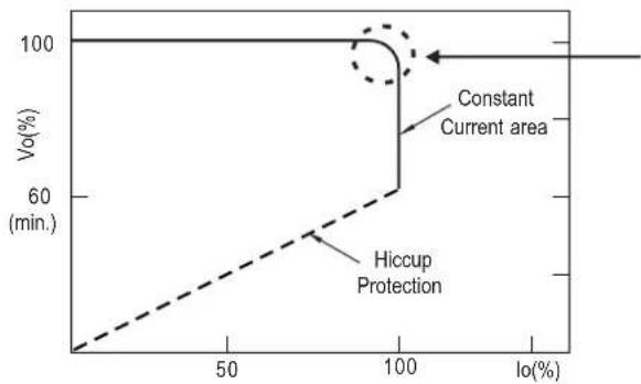
line
| Io(%) | Vo(%) | |-------|-------| | 0 | 100 | | 50 | 100 | | 100 | 60 | | 150 | 100 |In the constant current region, the highest voltage at the output of the driver depends on the configuration of the end systems.
Should there be any compatibility issues, please contact MEAN WELL.
Typical output current normalized by rated current (%)
DIMMING OPERATION

※ 3 in 1 dimming function (for B/AB-Type)
- Output constant current level can be adjusted by applying one of the three methodologies between DIM+ and DIM-:
1 \~ 10VDC, or 10V PWM signal or resistance. - Direct connecting to LEDs is suggested. It is not suitable to be used with additional drivers.
- Dimming source current from power supply: 100 A (typ.)μ
○ Applying additive 1 \~ 10VDC

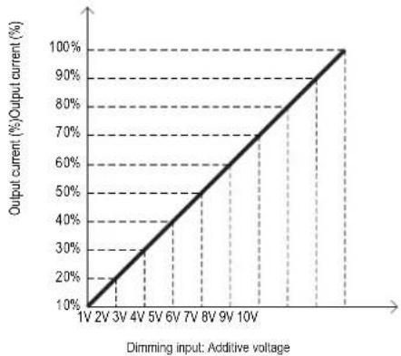
line
| Dimming input: Additive voltage | Output current (%)/Output current (%) | | ------------------------------- | ------------------------------------- | | 1V | 10% | | 2V | 20% | | 3V | 30% | | 4V | 40% | | 5V | 50% | | 6V | 60% | | 7V | 70% | | 8V | 80% | | 9V | 90% | | 10V | 100% |◎ Applying additive 10V PWM signal (frequency range 100Hz \~ 3KHz):

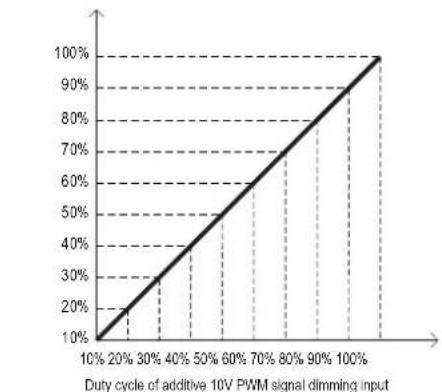
line
| Duty cycle of additive 10V PWM signal dimming input | Value | | -------------------------------------------------- | ----- | | 10% | 10% | | 20% | 20% | | 30% | 30% | | 40% | 40% | | 50% | 50% | | 60% | 60% | | 70% | 70% | | 80% | 80% | | 90% | 90% | | 100% | 100% |◎ Applying additive resistance:

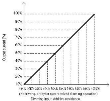
line
| Dimming Input: Additive resistance (N=driver quantity for synchronized dimming operation) | Output current (%) | | :--- | :--- | | 10K/N | 10 | | 20K/N | 20 | | 30K/N | 30 | | 40K/N | 40 | | 50K/N | 50 | | 60K/N | 60 | | 70K/N | 70 | | 80K/N | 80 | | 90K/N | 90 | | 100K/N | 100 |Note: In the case of turning the lighting fixture down to 0% brightness, please refer to the configuration as follow, or please contact MEAN WELL for other options.

flowchart
graph TD
    A["N FG L"] --> B["Relay"]
    B --> C["Switch Adjuster"]
    C --> D["10K/N~100K/N Ohms resistance"]
    C --> E["1~10V DC Voltage"]
    C --> F["10V PWM Signal"]
    G["Green/Yellow"] --> H["Brown"]
    H --> I["AC/L"]
    H --> J["AC/N"]
    K["Blue"] --> I
    K --> J
    L["HBG-100 B-Type"] --> M["DIM+"]
    L --> N["DIM-"]
    L --> O["V(-)"]
    L --> P["V(+)"]
    Q["Purple"] --> R["Pink"]
    S["Black"] --> T["Red"]
    U["LED Lighting Fixture"] --> V["Red"]
    W["AC/L"] --> X["Blue"]
    Y["AC/N"] --> Z["Blue"]
Using a switch and relay can turn ON/OFF the lighting fixture.
※ DALI Interface (primary side; for DA-Type)
- Apply DALI signal between DA+ and DA-.
• DALI protocol comprises 16 groups and 64 addresses. - First step is fixed at 8% of output.
■ OUTPUT LOAD vs TEMPERATURE(Note.9)

line
| Ambient Temperature, Ta ( )°C | LOAD (%) | | ---------------------------- | -------- | | -40 | 100 | | -25 | 100 | | 60 | 0 |
line
| Tcase (°C) | LOAD (%) | | ---------- | -------- | | - | 100 | | 4 | 100 | | 5 | 100 |■ STATIC CHARACTERISTIC

line
| INPUT VOLTAGE (V) 60Hz | LOAD (%) | | ---------------------- | -------- | | 90 | 80 | | 100 | 100 | | 305 | 100 |※De-rating is needed under low input voltage.
■ POWER FACTOR (PF) CHARACTERISTIC

line
| LOAD (100W) | 277V | 230V | 115V | |-------------|--------|--------|--------| | 50% | 0.94 | 0.968 | 0.992 | | 60% | 0.95 | 0.972 | 0.993 | | 70% | 0.955 | 0.975 | 0.994 | | 80% | 0.96 | 0.978 | 0.994 | | 90% | 0.965 | 0.98 | 0.995 | | 100% | 0.968 | 0.982 | 0.995 | | 110% | 0.97 | 0.985 | 0.995 | | 120% | 0.972 | 0.987 | 0.995 | | 130% | 0.973 | 0.988 | 0.995 | | 140% | 0.974 | 0.989 | 0.995 | | 150% | 0.975 | 0.99 | 0.995 |■ TOTAL HARMONIC DISTORTION (THD)

line
| LOAD | 277VAC | 230VAC | 115VAC | |------|--------|--------|--------| | 50% | 16% | 15% | 9% | | 60% | 14% | 13% | 8% | | 70% | 12% | 12% | 8% | | 80% | 11% | 11% | 8% | | 90% | 10% | 10% | 8% | | 100% | 10% | 10% | 8% |■ EFFICIENCY vs LOAD
HBG-100 series possess superior working efficiency that up to 91% can be reached in field applications.
※ 48V Model, Tcase at 75°C

line
| LOAD | 277V | 230V | 115V | |-------|-------|-------|-------| | 10% | 83.5 | 84.0 | 83.0 | | 20% | 86.0 | 88.0 | 82.0 | | 30% | 82.0 | 82.0 | 87.0 | | 40% | - | 86.0 | 89.0 | | 50% | - | 88.0 | 90.0 | | 60% | - | 89.0 | 90.5 | | 70% | - | 90.0 | 90.5 | | 80% | - | 91.0 | 90.5 | | 90% | - | 91.5 | 90.5 | | 100% | - | 91.5 | 90.0 |LIFE TIME
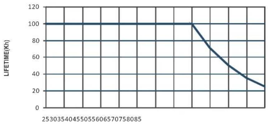
Tcase)(℃)
MECHANICAL SPECIFICATION
Case No.217 Unit:mm
Blank-Type
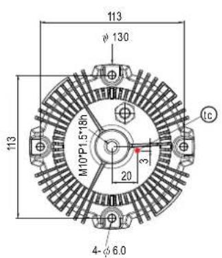

• tc : Max. Case Temperature.(case temperature measured point)
• Ta: Ambient Temperature measured point
※ A-Type

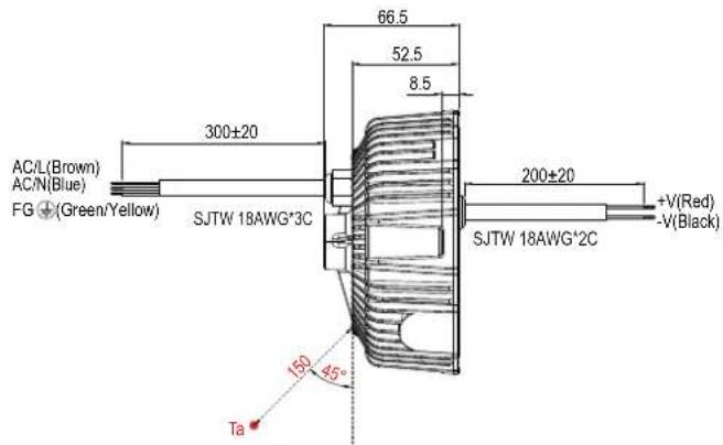
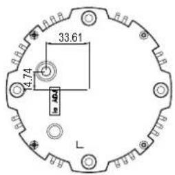
• (tc) : Max. Case Temperature.(case temperature measured point)
• Ta: Ambient Temperature measured point
※ B/DA-Type


• tc : Max. Case Temperature.(case temperature measured point)
• Ta: Ambient Temperature measured point
※ AB-Type

• (tc): Max. Case Temperature.(case temperature measured point)
• Ta: Ambient Temperature measured point
INSTALLATIONS
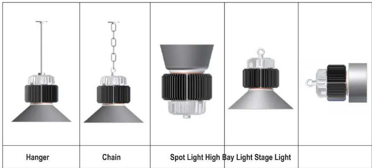
Caution
- Please inspect the appearance of the driver if the package is damaged. There should not be any cracks.
- Please do not drop or bump the driver.
- All screws including the suspension screw should be paired with a spring washer and locked tight.
- The entire luminaire, including the driver, should be limited to 10Kg or less.
- The luminaire should be cautiously protected from damage due to shock throughout packaging and transportation.
- Please thoroughly follow the preceding cautionary notes to prevent the luminaire from falling, leading to injuries.
Brand : Mean Well
Model : HBG-100-48B
Category : LED Controller