
VMBSTART-B-10 - Home Automation Velbus - Free user manual and instructions
Find the device manual for free VMBSTART-B-10 Velbus in PDF.


| Type of product | Bus start module for Velbus home automation system |
| Model | VMBSTART-B-10 |
| Brand | Velbus |
| Dimensions (H x W x D) | 90 x 53 x 58 mm (3 DIN modules) |
| Weight | Approx. 100 g |
| Power supply | 24 V DC from Velbus bus |
| Bus current consumption | < 50 mA |
| Operating temperature | 0°C to +45°C |
| Storage temperature | -20°C to +70°C |
| Relative humidity | 10% – 90%, non-condensing |
| Main functions | Initializes Velbus bus, provides bus termination and status indication |
| LED indicators | 1 green LED for bus status, 1 red LED for error |
| Bus connection | 4-pin screw terminal (V+, V-, D+, D-) |
| Installation | DIN rail mount in distribution board |
| Protection class | IP20 |
| Maintenance | Clean with a dry, soft cloth; do not use solvents |
| Safety instructions | Disconnect power before installation; use only by qualified personnel |
| Spare parts | None available; device is not user-serviceable |
| Reparability | Not repairable; replace unit |
| Certifications | CE, RoHS |
| Manual language | English (5 pages PDF) |
Frequently Asked Questions - VMBSTART-B-10 Velbus
User questions about VMBSTART-B-10 Velbus
0 question about this device. Answer the ones you know or ask your own.
Ask a new question about this device
Download the instructions for your Home Automation in PDF format for free! Find your manual VMBSTART-B-10 - Velbus and take your electronic device back in hand. On this page are published all the documents necessary for the use of your device. VMBSTART-B-10 by Velbus.
USER MANUAL VMBSTART-B-10 Velbus
Congratulations on your purchase of the Velbus Starter Kit!
This quick start guide will walk you through the installation step by step.
Need a more detailed manual? Scan the QR code to access the
product page and find additional support under the "Support" tab.

Step 1: Connecting the Components
Connect the components of the set as shown on the connection diagram:

flowchart
graph TD
    A["VMBELO-X-20"] --> B["EIB"]
    B --> C["Extra module(s)"]
    C --> D["VMB4RYNO-10"]
    D --> E["VMBPSU-2"]
    E --> F["L N"]
    F --> G["bus L H +"]
    style A fill:#333,stroke:#fff,color:#fff
    style B fill:#999,stroke:#000,color:#fff
    style C fill:#ccc,stroke:#000,color:#fff
    style D fill:#666,stroke:#000,color:#fff
    style E fill:#999,stroke:#000,color:#fff
    style F fill:#ccc,stroke:#000,color:#fff
    note right of A: "Important notes: You can add multiple Velbus DIN rail modules between the VMBUSB and VMB4RYNO modules."
    classDef module fill:#e6f7ff,stroke:#333;
    class A,B,C,D,E,F,G,H,I,J,K,L,M,N,O,P,Q,R,S,U,V,W,X,Y,Z,Z,N,O,P,P,Q,P,P,P,P,P,P,P,P,P,P,P,P,P,P,P,P,P,P,P,P,P,P,P,P,P,P,P,P,P,P,P,P,P,P,P,P,P,P,P,P,P,P,P,P,P,P,P,P,P,P,P,P,P,P,P,P,P,P,P,P,P,P,P,P,P,P,P,P,P,P,P,P,P,P,P,P,P,P,P,P,P,P,P,P,P,P,P,P,P,P,P,P,P,P,P,P,P,P,P,P,p,p,p,p,p,p,p,p,p,p,p,p,p,p,p,p,p,p,p,p,p,p,p,p,p,p,p,p,p,p,p,p,p,p,p,p,p,p,p,p,p,p,p,p,p,p,p,p,p,p,p,p,p,p,p,p,p,p,p,p,p,p,p,p,p,p,p,p,p,p,p,p,p,p,p,p,p,p,p,p,p,p,p,p,p,p,p,p,p,p,p,p,p,p,p,p,p,p,p,p,\n\nboxplus box at bottom
Important notes:
- You can add multiple Velbus DIN rail modules between the VMBUSB and VMB4RYNO modules.
- Use the included Molex cable to connect the VMB4RYNO module to the VMBPSU module. Cut off one side of the Molex connector, strip the black (-) and red (+) wires, and connect them to the VMBPSU.
- The Molex connections on the VMB4RYNO and VMBUSB modules are internally connected. It does not matter which port you use.
- Each DIN rail module comes with a Molex cable for daisy-chaining the bus. Need additional (longer) cables? See our VMBCABLE20SET, VMBCABLE40SET and VMBCABLE150SET.
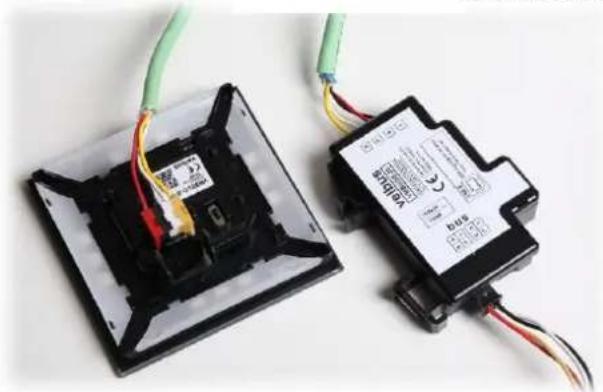
- Strip both ends of the EIB cable and connect them to the connectors on the VMBELO and VMBUSB modules. Follow the color coding of the bus connections:
Red Voltage 15V (± 3V) +
Black Voltage 0V -
White CANbus Low L
Yellow CANbus High H

natural_image
Two pliers with black and red wires, one connected to a black connector (no text or symbols visible)Overview cable sets:

natural_image
Two electronic components with wires and colored wires, one open showing internal wiring and the other closed (no visible text or symbols)Step 2: Configuring the Terminators
All Velbus modules (except the VMBUSB-20) are equipped with a terminator (a switch marked "TERM") that is open by default. In every Velbus installation, at least two terminators must be closed, with as much cable distance as possible between them. These are usually the first and last (farthest) modules in the installation.
For DIN rail modules, open the front panel to access the terminator. For other modules, the terminator is located on the back. The terminator is enabled when the corresponding LED is lit.


In this basic setup, close the terminator on both the VMBELO panel and the VMB4RYNO module.
Step 3: Checking the BUS Connection
Velbus is a highly stable system, but any issues are usually caused by poor BUS connections. Always perform the following check during the initial installation and after any cabling changes:
Press any button on a module (except the RESET button). You will see the LED next to the TX (transmit) marking light up briefly. At the same time, the RX (receive) LEDs on all other modules in your installation will also briefly light up. This indicates that a signal from the module is correctly placed on the bus and received by the other modules.
Repeat this test for all other modules in your installation (except for the VMBUSB module, as it has no buttons). If the other modules do not respond to the signal, double-check the cabling and follow our troubleshooting guide.
Step 4: Programming via PC
- Download the latest Velbuslink software from www.velbus.eu/downloads. The installation does not require admin rights unless you want to install the optional USB drivers.
- Connect the VMBUSB module to your computer using the included USB cable after installing Velbuslink, and start the program.
- Click on "New" (top left) to start the "Create a new project" wizard. Select Next for the following options: "Connect to an existing installation" and "Direct connection via cable".

During the scanning of the installation, you may allow automatic address assignment.
Do not do this if you are reading an existing (functioning) installation.

Select how modules are added to your project:
Scan my installation for modules
√ Auto-assign addresses
○ Start with an empty project and add modules later
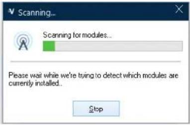
For a new project (as with this starter kit), you can choose to start with empty modules in this screen. For an existing (functioning) installation, first read all the settings. Depending on the size of the installation, this may take some time.

Select whether or not the module memories are retrieved:
○ Read settings from my existing installation (recommended) (Modules with an invalid address will not be read)
Start with blank modules
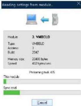
Once the reading process is complete, a confirmation message will appear, and you can start configuring.
Press Finish to start configuring your installation.
- In the navigation panel, you will now see both the VMBELO and VMB4RYNO modules. You can expand the channels of a module by clicking on the "+" symbol next to their names.

- Left-click on the name of the selected module or channel to rename it. For example, change "Relay 1" to "Kitchen Light".
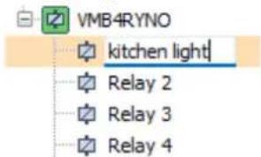
- Drag "Button 1" from the VMBELO module to the VMB4RYNO module and drop it on Relay 1 ("Kitchen Light"). In the dialog box, select the action "Toggle" and press OK.
![Name MyProject.vlp VMBELO 3 VMBELO 2047 Push button 1 CH1 Transgate Push button 2 CH2 Released Push button 3 CH3 Released Push button 4 CH4 Released Push button 5 CH5 Released Push button 6 CH6 Released Push button 7 CH7 Released Push button 8 CH8 Released Temp. sensor CH33 25,5 °C Output CH42 Off VMB4RYNO 19 VMB4RYNO 2436 Action properties Initiator: 3.VMBELO, Push button 1 (CH1) Subject: 19.VMB4RYNO, kitchen light (CH1) Action Most used On 0101 Off 0102 Toggin Mannerley (follow) 0104 Start/stop timer 0405 Non restatable timer 0407 Restarable timer 0412 [01] General [04] Timer [05] Delays Show categories](/content/2026/05/1095056/images/e67fa0752e4500dd00a0cc62d01ba3be47a754bf9bf21ea6a61dbe544feecc05.jpg)
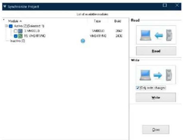
- Press the "Synchronize" button.
In the "Project Synchronization" window, check "Only changes" and press "Write".
When the writing process is complete (this should only take a few seconds), you can now control Relay 1 ("Kitchen Light") by pressing the left button (Button 1) on the glass control panel.
- To modify the text on the OLED screen, select the VMBELO module in Velbuslink and click on the gear icon (or press F6).

- In the configuration window, click the button "Create a new image" and add names and icons.
| General | Preferences | Screenaver | Button mode | Sensitivity | Feedback mode |
| Name | Response time | |
| Button 1 | Push button 1 | Immediately |
| Button 2 | Push button 2 | Immediately |
| Button 3 | Push button 3 | Immediately |
| Button 4 | Push button 4 | Immediately |

The configuration window also offers many other settings related to backlighting, navigation, screensavers, etc. Feel free to check the product page of the VMBELO module to explore the possibilities.
Do not forget to synchronize (save changes to the modules) before testing the changes you made.
Additional Information
On the website www.velbus.eu/downloads, you can find three important documents in the installation guide section: the Hardware Installation Guide, the Software Configuration Guide, and the Troubleshooting Guide. We recommend reading these documents carefully to fully explore the capabilities of Velbus.

Troubleshooting
If the system is not functioning correctly, carefully check the wiring, ensure the terminators are configured properly and restart the installation (briefly interrupt the power supply).
If the problem persists, visit the support pages at www.velbus.eu or contact your Velbus distributor. Technical support is available via the Velbus ticket system: help.velbus.eu.
Warnings
Velbus products are intended for installation by a professional installer:
- All work must be performed on a de-energized installation.
• The installation must comply with the applicable regulations of your country. - Follow proper workmanship practices.
If in doubt, contact your wholesaler.
Contact
Velbus is a Belgian brand developed and produced by Velleman Group NV in Gavere. With over 25 years of experience in the home automation market and 50 years of expertise in electronics development, we support professionals and makers in realizing their projects.
Velleman Group nv
Legen Heirweg 33
9890 GAVERE
Belgium
+32 9 384 36 11
info@velleman.eu
BE 0768 858 127
velleman GROUP



Brand : Velbus
Model : VMBSTART-B-10
Category : Home Automation