ANI-41STREAM - Video transmitter A-NeuVideo - Free user manual and instructions
Find the device manual for free ANI-41STREAM A-NeuVideo in PDF.


| Product Type | Multimedia Streaming Player |
| Brand | A-NeuVideo |
| Model | ANI-41STREAM |
| Dimensions (W x D x H) | 12.5 x 8.5 x 2.5 cm |
| Weight | 200 g |
| Power Supply | DC 5V, 2A via USB |
| Supported Video Formats | MP4, AVI, MKV, MOV |
| Supported Audio Formats | MP3, WAV, AAC, FLAC |
| Max Resolution | 4K UHD (3840 x 2160) |
| Connectivity | HDMI 2.0, USB 2.0, Wi-Fi 802.11 b/g/n, Ethernet |
| Remote Control | Infrared (included) |
| Storage Expansion | microSD card slot up to 128GB |
| Operating System | Proprietary (Linux-based) |
| Functions | Streaming from Netflix, YouTube, Amazon Prime Video, etc. |
| Maintenance | Clean with dry cloth; avoid liquids. |
| Safety | Use only included power adapter; keep away from moisture. |
| Spare Parts Available | Remote control, power adapter sold separately. |
| General Information | Streams content from popular services; supports 4K output. |
Frequently Asked Questions - ANI-41STREAM A-NeuVideo
User questions about ANI-41STREAM A-NeuVideo
0 question about this device. Answer the ones you know or ask your own.
Ask a new question about this device
Download the instructions for your Video transmitter in PDF format for free! Find your manual ANI-41STREAM - A-NeuVideo and take your electronic device back in hand. On this page are published all the documents necessary for the use of your device. ANI-41STREAM by A-NeuVideo.
USER MANUAL ANI-41STREAM A-NeuVideo
4x1 Multi-Input to HDBT Live Video Streaming Transmitter w/ Recording

PACKAGE CONTENTS
Before attempting to use this unit, please check the packaging and make sure the following items are contained included:
• ANI-41STREAM 4x1 Multi-Input to HDBT Live Video Streaming Transmitter w/Recording
• 24V/3.75A DC Power Adapter
- AC Power Cord
• (2) 5-pin Terminal Block
• (2) 4-pin Terminal Block
- IR Blaster Cable
- IR Extender Cable
-
To ensure the best results from this product, please read this manual and all other documentation before operating your equipment. Retain all documentation for future reference.
-
Follow all instructions printed on unit chassis for proper operation.
-
To reduce the risk of fire, do not spill water or other liquids into or on the unit, or operate the unit while standing in liquid.
-
Make sure power outlets conform to the power requirements listed on the back of the unit. Keep unit protected from rain, water and excessive moisture.
-
Do not attempt to clean the unit with chemical solvents or aerosol cleaners, as this may damage the unit. Dust with a clean dry cloth.
-
Do not use the unit if the electrical power cord is frayed or broken. The power supply cords should be routed so that they are not likely to be walked on or pinched by items placed upon or against them, paying particular attention to cords and plugs, convenience receptacles, and the point where they exit from the appliance.
-
Do not force switched or external connections in any way. They should all connect easily, without needing to be forced.
-
Always operate the unit with the AC ground wire connected to the electrical system ground. Precautions should be taken so that the means of grounding of a piece of equipment is not defeated.
-
AC voltage must be correct and the same as that printed on the rear of the unit. Damage caused by connection to improper AC voltage is not covered by any warranty.
-
Turn power off and disconnect unit from AC current before making connections.
-
Never hold a power switch in the "ON" position.
-
This unit should be installed in a cool dry place, away from sources of excessive heat, vibration, dust, moisture and cold. Do not use the unit near stoves, heat registers, radiators, or other heat producing devices.
-
Do not block fan intake or exhaust ports. Do not operate equipment on a surface or in an environment which may impede the normal flow of air around the unit, such as a bed, rug, carpet, or completely enclosed rack. If the unit is used in an extremely dusty or smoky environment, the unit should be periodically "blown free" of foreign dust and matter.
-
To reduce the risk of electric shock, do not remove the cover. There are no user serviceable parts inside. Refer all servicing to qualified service personnel. There are no user serviceable parts inside.
-
When moving the unit, disconnect input ports first, then remove the power cable; finally, disconnect the interconnecting cables to other devices.
-
Do not drive the inputs with a signal level greater than that required to drive equipment to full output.
-
The equipment power cord should be unplugged from the outlet when left unused for a long period of time.
-
Save the carton and packing material even if the equipment has arrived in good condition. Should you ever need to ship the unit, use only the original factory packing.
-
Service Information Equipment should be serviced by qualified service personnel when:
A. The power supply cord or the plug has been damaged.
B. Objects have fallen, or liquid has been spilled into the equipment.
C. The equipment has been exposed to rain.
D. The equipment does not appear to operate normally, or exhibits a marked change in performance.
E. The equipment has been dropped, or the enclosure damaged.
THIS SAFETY INFORMATION IS OF A GENERAL NATURE AND MAY BE SUPERSEDED BY INSTRUCTIONS CONTAINED WITHIN THIS MANUAL.
SAFETY PRECAUTIONS
Please read all instructions before attempting to unpack, install or operate this equipment and before connecting the power supply. Please keep the following in mind as you unpack and install this equipment:
• Always follow basic safety precautions to reduce the risk of fire, electrical shock and injury to persons.
- To prevent fire or shock hazard, do not expose the unit to rain, moisture or install this product near water.
- Never spill liquid of any kind on or into this product.
- Never push an object of any kind into this product through any openings or empty slots in the unit, as you may damage parts inside the unit.
- Do not attach the power supply cabling to building surfaces.
- Use only the supplied power supply unit (PSU). Do not use the PSU if it is damaged.
- Do not allow anything to rest on the power cabling or allow any weight to be placed upon it or any person walk on it.
- To protect the unit from overheating, do not block any vents or openings in the unit housing that provide ventilation and allow for sufficient space for air to circulate around the unit.
DISCLAIMERS
The information in this manual has been carefully checked and is believed to be accurate. We assume no responsibility for any infringements of patents or other rights of third parties which may result from its use.
We assume no responsibility for any inaccuracies that may be contained in this document. We make no commitment to update or to keep current the information contained in this document.
We reserve the right to make improvements to this document and/or product at any time and without notice.
COPYRIGHT NOTICE
No part of this document may be reproduced, transmitted, transcribed, stored in a retrieval system, or any of its part translated into any language or computer file, in any form or by any means — electronic, mechanical, magnetic, optical, chemical, manual, or otherwise — without the express written permission and consent.
© Copyright 2020. All Rights Reserved.
Version 1.0 MAR 2020
TRADEMARK ACKNOWLEDGMENTS
All products or service names mentioned in this document may be trademarks of the companies with which they are associated.
TABLE OF CONTENTS
A NEUVIDEO
INTRODUCTION....2
APPLICATIONS / SYSTEM REQUIREMENTS....3
FEATURES 4
SPECIFICATIONS......5
OPERATION CONTROLS & FUNCTIONS....6
RS-232 PINOUT & DEFAULTS....8
WEBGUI CONTROL....9
TELNET CONTROL....20
CONNECTION DIAGRAM....32
VIDEO SPECIFICATIONS....33
AUDIO SPECIFICATIONS....37
CABLE SPECIFICATIONS....38
HDBASET™ FEATURES 39
INTRODUCTION
The ANI-41STREAM Video Streaming Transmitter with Recording makes online broadcasting of live video, with a locally stored archive, an easy and simple process. Video sources from cameras, PCs, video game consoles, etc. are a breeze to connect for immediate broadcast and recording. Video content up to 4K UHD (4K@60Hz, 4:2:0, 8-bit) is supported and is automatically scaled to a resolution that is more appropriate for efficient streaming. In addition to the standard HDMI input, DisplayPort, USB-C and VGA (with paired audio) inputs are also supported as sources. Along with the streaming and recording functionality, an HDBaseT™ output is provided for local, or long distance (up to 70m at 1080p when using CAT6A), monitoring of the selected input source when connected to a compatible receiver.
All video content is encoded and streamed with minimal latency and high quality making it ideal for live streaming events to a variety of popular online streaming services or within the local network. The video may also be recorded locally (via USB thumb drive) or to a local network drive while it is being streamed.
A trigger input interface is also provided to allow the easy addition of a remote control keypad, or other trigger-supporting products, which can be installed within a podium or within a table in a conference room or classroom. This interface can allow the user to activate functions with the simple press of a button.
Comprehensive EDID management provides improved compatibility with different sink devices. The intuitive WebGUI provides easy control of your live event stream including source selection, resolution, bitrate and more. This unit can be controlled and configured via front panel buttons, an intuitive WebGUI, Triggers, RS-232, or Telnet. This unit comes with a 3 year warranty.
APPLICATIONS
- Webcasting
• Social Media Broadcasting
• Live Event Streaming
• Video on Demand Streaming
• Live recording and storage
SYSTEM REQUIREMENTS
- HDMI, VGA, DisplayPort or USB-C source equipment such as a media player, video game console, PC, or video camera.
• Available streaming server destination such as YouTube or Facebook or a recording storage target such as USB thumb drive or NAS. - A compatible HDBaseT™ receiver with PoH(PD) support is recommended.
- The use of Premium High Speed HDMI cables, and industry standard CAT6, CAT6A or CAT7, is highly recommended.
- Video streaming preview support within the WebGUI requires the use of the Chrome, Internet Explorer or Safari browser with the appropriate plugins (VLC for IE and Safari or VXG Player for Chrome) installed.
Note: The Firefox browser does not currently support the WebGUI's video streaming preview window. - To view RTSP streams directly on the local network, RTSP stream compatible video player software (such as VLC Media Player or PotPlayer) must be used.
FEATURES
• (4) inputs (HDMI, DisplayPort, USB-C, and VGA)
• (1) HDBaseT™ output
• Digital inputs are HDCP 1.x and HDCP 2.2 compliant
Note: HDCP encrypted sources cannot be streamed over the Internet or recorded and will be blacked out
- HDMI, DisplayPort, and USB-C inputs support resolutions up to 4K UHD (4K@60Hz, 4:2:0, 8-bit)
• VGA input supports resolutions up to 1080p@60Hz and is paired with an analog stereo audio input
- HDBaseT™ output supports resolutions up to 4K UHD (4K@60Hz, 4:2:0, 8-bit)
- Advanced H.264 video streaming and recording is provided at QVGA (320x240), VGA (640x480), 720p, or 1080p at up to 60fps
- Recorded video can be stored on a locally inserted USB thumb drive, or to a designated network drive
- Can act as a streaming server (using RTP/RTSP protocols) or streaming client (using the RTMP protocol)
- Trigger Control Keypad support for easy, single-button, function activation (Optional)
• Supports scheduled recording with an internet updated calendar
• Supports text overlays over live broadcasts
- Integrated downscaling function will convert UHD video content (up to 4K@60Hz) down to 1080p or lower for live video broadcast and recording
- Generates (4) simultaneous streams from the same video source (1080p@60fps, 1080p@30fps, VGA@30fps, QVGA@30fps) for easy system integration at multiple bandwidth targets
• Supports automatic input switching
- Advanced EDID management including Internal, External & User configured EDID selections
- Control via front panel buttons, WebGUI, Triggers, Telnet, and RS-232
• HDMI Bandwidth: 10.2Gbps
• DisplayPort Bandwidth: 10.2Gbps
• USB-C Bandwidth: 10.2Gbps
• VGA Bandwidth: 165MHz
- HDBaseT™ Bandwidth: 10.2Gbps
- Input Ports:
- HDMI (Type-A)
- DisplayPort
- USB (Type-C)
• VGA (HD-15) - Analog Stereo (3.5mm)
• Output Port: HDBaseT™ (RJ-45)
• Control/Streaming Port: LAN (RJ-45)
• Pass-through Ports:
- IR Extender (3.5mm)
- IR Blaster (3.5mm)
• RS-232 (4-pin Terminal Block)
- Control Ports:
• RS-232 (4-pin Terminal Block)
- Trigger (10-pin Terminal Block)
• Service Port: USB 2.0 (Type-A)
- IR Frequency: 30 \~ 50kHz (30 \~ 60kHz under ideal conditions)
• Baud Rate: 19200 (Control) Up to 115200 (Bypass)
• Power Supply: 24V/3.75A DC (US/EU standards, CE/FCC/UL certified)
• ESD Protection (HBM):
- ±8kV (Air Discharge)
- ±4kV (Contact Discharge)
- Dimensions (WxHxD): 9.1 x 1 x 5.9 in (231.5x25x150mm) [Case Only] / 9.1 x 1 x 6.1 in (231.5x25x158mm) [All Inclusive]
• Weight: 2 lbs / 909g
• Chassis Material: Metal (Steel)
- Chassis Color: Black
- Operating Temperature: 0°C - 40°C / 32°F - 104°F
- Storage Temperature: -20°C - 60°C / -4°F - 140°F
- Relative Humidity: 20 – 90% RH (Non-condensing)
• Power Consumption: 39.84W
As product improvements are continuous, specifications are subject to change without notice.
OPERATION CONTROLS & FUNCTIONS
FRONT PANEL
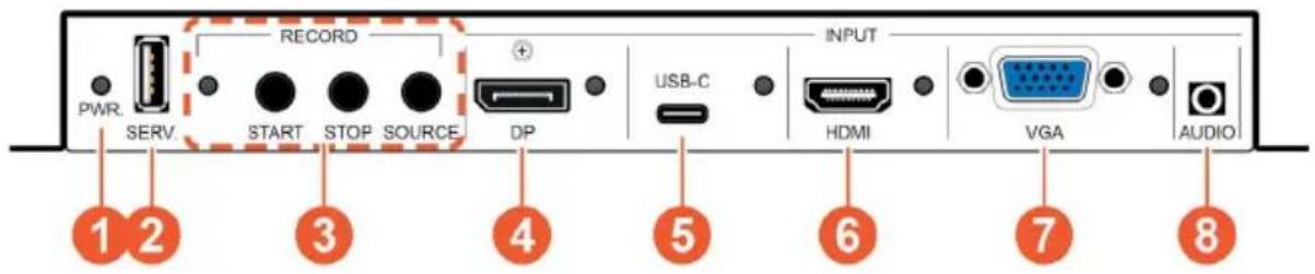
① PWR. LED: This LED will illuminate to indicate the unit is on and receiving power.
② SERV. Port: Attach a standard USB thumb drive or external hard drive for storage of recorded video. (Optional)
Note: Storage media must be formatted as FAT32 or exFAT. Video files are stored in *.mp4 format.
3 RECORD LED: This LED will blink while video recording is active.
RECORD START BUTTON: Press this button to immediately start recording to the designated recording target.
RECORD STOP BUTTON: Press this button to immediately stop any current recording session.
RECORD SOURCE BUTTON: Press this button to sequentially switch through the available inputs. Note: Changing the input source will cause the video stream to restart. Connected stream targets may need to be restarted or reconnected.
④ DP INPUT PORT & LED: Connect to DisplayPort source equipment such as a PC or laptop. The LED will illuminate amber when a source is detected and green when the source is selected.
⑤ USB-C INPUT PORT & LED: Connect to USB Type-C video source equipment such as a PC or laptop. The LED will illuminate amber when a source is detected and green when the source is selected.
Note: Not all devices with USB Type-C ports can support video output. Please verify that the device supports video output from the USB Type-C port before connecting it.
⑥ HDMI INPUT PORT & LED: Connect to HDMI source equipment such as a media player, game console, or set-top box. The LED will illuminate amber when a source is detected and green when the source is selected.
⑦ VGA INPUT PORT & LED: Connect to VGA source equipment such as a PC or laptop. The LED will illuminate amber when a source is detected and green when the source is selected.
8 AUDIO INPUT PORT: Connect to the stereo analog output of the device connected to the VGA input port.
Note: Audio from this port is embedded with the VGA video source.
OPERATION CONTROLS & FUNCTIONS
REAR PANEL

1 IR EXTENDER PORT: Connect to an IR Extender to receive IR control signals and extend them to devices connected to the other end of the HDBaseT™ connection. Ensure that the remote being used is within direct line-of-sight of the IR Extender.
IR BLASTER PORT: Connect to an IR Blaster to transmit IR signals from the other end of the HDBaseT™ connection to devices within direct line-of-sight of the IR Blaster.
② CAT5E/6/7 OUT PORT: Connect to a compatible HDBaseT™ Receiver with a single CAT5e/6/7 cable for transmission of all data signals. PoH will also be supplied to a connected compatible PD Receiver.
③ RS-232 4-PIN TERMINAL BLOCK (TOP): Connect directly to a PC or laptop, or other serial control device with a 3 or 4-pin adapter cable (as appropriate) to send RS-232 commands to control the unit. RS-232 BYPASS 4-pin Terminal Block (Bottom): Connect to a PC, laptop, or serial controllable device with a 3-pin adapter cable for the extension of RS-232 signals between both ends of the HDBaseT™ connection.
④ TRIGGER 10-PIN TERMINAL BLOCK: Connect to the Trigger Control Keypad (OPTIONAL) or any device with trigger switch functionality to control assigned functions of the unit.
Note: A minimum of 5V DC is required to activate a trigger.
⑤ LAN PORT: Connect to a network switch or router for transmission and distribution of streamed video as well as to control the unit via Telnet or WebGUI.
Note: The maximum number of simultaneous stream connections is limited by available network bandwidth and the unit's CPU load.
⑥ DC 24V PORT: Plug the 24V DC power adapter into this port and connect it to an AC wall outlet for power.
IR CABLE PINOUTS / RS-232 PINOUT & DEFAULTS
IR CABLE PINOUTS
IR Blaster Cable

IR Extender Cable

RS-232 PINOUT & DEFAULTS
| Serial Port Default Settings(Unit Control) | |
| Baud Rate 19200 | |
| Data Bits 8 | |
| Parity Bits None | |
| Stop Bits 1 1 | |
| Flow Control None | |
RS-232 PORT 1 (UNIT CONTROL)
4-pin Terminal Block
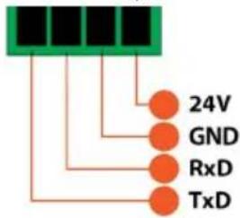
4-pin Terminal Block
RS-232 PORT 2 (BYPASS)
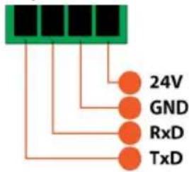
WEBGUI CONTROL
DEVICE DISCOVERY
Please obtain the "Device Discovery" software from your authorized dealer and save it in a directory where you can easily find it.
Connect the unit and your PC/Laptop to the same active network and execute the “Device Discovery” software. Click on “Find Devices on Network” and a list of devices connected to the local network will show up indicating their current IP address.
Note: The unit's default IP address is 192.168.1.50.
By clicking on one of the listed devices you will be presented with the network details of that particular device.
-
IP Mode: If you choose, you can alter the static IP network settings for the device, or switch the unit into DHCP mode to automatically obtain proper network settings from a local DHCP server. To switch to DHCP mode, please select DHCP from the IP mode dropdown, then click "Save" followed by "Reboot".
-
WebGUI Hotkey: Once you are satisfied with the network settings, you may use them to connect via Telnet or WebGUI. The network information window provides a convenient link to launch the WebGUI directly.
WEBGUI OVERVIEW

After connecting to the WebGUI's address in a web browser, the login screen will appear. Please enter the appropriate user name and password then click "Submit" to log in.
Note: The default user name and password is "admin".
| Live |
| Video Switch |
| Edid Setting |
| Record Setting |
| Time Setting |
| Trigger Setting |
| User Config |
| System Setting |
| Admin - Logout |
On the left side of the browser you will see the following menu tabs where all primary functions of the unit are controllable via the built in WebGUI. The individual functions will be introduced in the following sections.
Clicking the red "Logout" tab will automatically log the currently connected user out of the WebGUI and return to login page.
LIVE TAB
This tab provides viewing access to the first local video stream channel (of 4 channels total) generated by the unit. The video source can be selected here and the stream resolution, framerate and bitrate is also displayed. At the bottom of the page, a connection address for local video stream channel 1 is displayed in the format: "rtsp://xxx.xxx.xxx.xxx/live/ch1/h264_aac" (xxx.xxx.xxx.xxx = the unit's current IP address). When 3rd party video player
software with RTSP streaming support is used to view streams from this unit, this is the URL that should be used to connect. To view streaming channels 2\~4, change "ch1" in the address to "ch2", "ch3", or "ch4", as appropriate.
Note: The Channel 1 configuration is set on the "Record Setting" tab. Channels 2\~4 contain the same video content presented at different streaming resolutions. Channel 2 is 1920x1080@30fps, Channel 3 is 640x480@30fps, and Channel 4 is 320x240@30fps.
WEBGUI CONTROL
-
Source Select: Select the video input (DisplayPort, USB-C, HDMI or VGA) to stream. Note: Changing the input here will change it globally across the unit.
-
Video Codec: Indicates the video codec used for the video stream. Note: Currently, only H.264 is supported.
-
Maximum Resolution: Displays the current maximum resolution for streaming channel 1.
-
Maximum Framerate: Displays the current maximum framerate for streaming channel 1.
-
Maximum Quality: Displays the current maximum bitrate for streaming channel 1.
-
Video Window: This video window displays the content of streaming channel 1 and provides the details of a direct connection address that can be used to connect to this stream using 3rd party video player software such as VLC or PotPlayer.
Note: Video streaming preview support within the WebGUI requires the use of the Chrome, Internet Explorer or Safari browser with the appropriate plugins (VLC for IE and Safari or VXG Player for Chrome) installed.
VIDEO SWITCH TAB
This tab provides input routing control as well as control over input and output names, and OSD Text settings.
-
Auto Source Switch: Enable or disable the automatic input switching feature of this unit. When enabled, the unit will automatically switch to the most recently connected/detected input. If the current input's signal is lost, the unit will automatically switch to the other input.
-
OSD Text Screen: The OSD Text Screen can be used when the user wants to display a simple text message on screen while the video plays. It may be enabled or disabled here.
Note: The text that will be displayed is the current output name text.
WEBGUI CONTROL
-
Video Switch: To assign a new video route, please click the output button and then click on the button of the preferred input port to route. As you select each button they will change their color to orange. The new route will become active immediately and the routing information displayed on the buttons will change accordingly.
-
Output: Click on this button to begin routing selection as detailed above. Click the Edit icon (☑) to open the Output Edit window and modify additional output settings.
-
Input: Rename the input or view the current HDCP behavior (Digital inputs only) by clicking on the Edit icon (☑) to open the editing window. Click on “Save” to confirm and activate any changes made to a name.
-
Output Edit: This window is opened after clicking on the Edit icon (☐) within the output button and provides options to rename the output, and configure the settings for the OSD Text Screen. Click on "Save" to confirm and activate any changes made to the name. All other changes are immediate.
EDID SETTING TAB
This tab provides the option of four standard EDIDs, one sink sourced EDID and four customer uploaded EDIDs that can be assigned to the digital input ports. The names of the four customer uploaded EDIDs can changed if desired.
Note: The EDID used by the VGA port is fixed, and cannot be changed.
1. Customer EDID Settings:
- Save Name: To change the name of a custom EDID, type the new name in the space provided, then click on the "Save Name" button.
- Download: To save an existing custom EDID to your local PC please press the “Download” button next to the EDID you would like to save. Depending on your browser settings you will either be asked where to save the downloaded file, or the file will be transferred to the default download location on your PC.
-
Upload: To upload a custom EDID, please click the "Upload" button next to the Customer EDID Settings item you would like to change. An EDID Upload window will appear, allowing you to locate and upload the preferred EDID file (*.bin format) from a local PC. Once the correct file has been selected, please click the "Upload" button in the window, and the file will be transferred to the unit.
-
Sink EDID Download: To save the EDID from the connected HDBaseT™ display to your local PC, select the sink from the dropdown list then press the "Download" button. Depending on your browser settings you will either be asked where to save the downloaded file, or the file will be transferred to the default download location on your PC.
-
Set EDID Input Content: Click on the switch select how to assign EDIDs to the unit's inputs (Appoint/All). Selecting "Appoint" allows for a different EDID to be assigned to each input, selecting "All" allows for a single EDID to be assigned to all inputs. After making the mode selection, click on the input button to open the EDID Source selection window. Select the new EDID source to use, from the choices on the right, and the change will occur immediately.
Note: In most cases, assigning a new EDID to an input will cause the affected input to briefly blink out while the source adapts to the new information.
This unit provides the following 4 default EDIDs:
| Unit's Default EDIDs | |
| FHD 2CH 1920x1 | 080p@60Hz (4.95Gbps) & 8-bit color, LPCM 2.0 |
| FHD MCH 1920x1 | 1080p@60Hz (4.95Gbps) & 8-bit color, LPCM 7.1 & Bitstream |
| 4K UHD 2CH 384 | 40x2160p@30Hz (10.2Gbps) & Deep Color (8/10/12-bit), LPCM 2.0 |
| 4K UHD MCH 384 | 40x2160p@30Hz (10.2Gbps) & Deep Color (8/10/12-bit), LPCM 7.1 & Bitstream |
Note: In some rare cases it is possible for custom or external EDIDs to cause compatibility issues with certain sources. If this happens, it is recommended to switch to one of the 4 default EDIDs for maximum compatibility.
RECORD SETTING TAB
This tab provides access to the settings and controls for configuring the channel 1 stream (the same stream viewed on the "Live" tab) and making a recording of it to a local or network storage location. When recording is enabled, the channel 1 video stream is saved as a *.mp4 file, encoded with the H.264 codec, to one of three possible target destinations: USB storage, network storage using NFS, or network storage using CIFS. The file will be placed within an automatically named folder structure based on the current date and time of the recording to facilitate easy sorting and file management. It is also possible to set up automatic daily recording times based on a repeating weekly schedule structure.
- Record: Enable or disable recording the channel 1 video stream. When enabled, recording will begin immediately to the selected storage location.
Note: HDCP encrypted sources cannot be recorded. - Storage: Use the drop-down to select the storage target to use when recording. Available choices are: Auto, USB (USB storage), NFS (NFS based network storage), and CIFS (CIFS based network storage). Selecting “Auto” will use the first available valid storage location using the following priority order: NFS > CIFS > USB
- Overwrite: Enables or disables the file overwrite function. When enabled, the unit will automatically delete older recordings, when space runs out on the selected storage location, to make room for new recordings.
- Record Resolution: Select the maximum resolution to use for streaming channel 1. Available resolutions are: 1080p(1920x1080), 720p(1280x720), VGA(640x480), or QVGA(320x240).
Note: The recording resolution will not exceed the original source's resolution even if a higher maximum is selected.
- Record Framerate: Select the framerate to use for streaming channel 1. Available framerates are: 25, 30, 50, or 60 frames per second.
- Record Quality: Select the target bitrate for streaming channel 1. Available bitrates are: Best (6000Kbps), High (3000Kbps), or Normal (2000Kbps).
-
Remote Storage (NAS) NFS: This section provides a way to configure access to a NAS (Network Attached Storage) device using the NFS protocol.
-
Enable: Enable or disable access to the defined NFS based network storage server.
- Remote IP: Enter the IP address of the target NFS based NAS device. After entering the information, press the "Save" button.
- Folder: Enter a valid share name on the target server. The share name cannot contain spaces or special characters. This is where the recording folder structure and video files will be created. After entering the information, press the “Save” button.
Note: The target folder on the NFS server must, at a minimum, provide anonymous read, write and delete permissions.
-
Remote Storage (NAS) CIFS: This section provides a way to configure access to a NAS (Network Attached Storage) device using the CIFS protocol.
-
Enable: Enable or disable access to the defined CIFS based network storage server.
- Remote IP: Enter the IP address of the target CIFS based NAS device. After entering the information, press the "Save" button.
- Folder: Enter a valid share name on the target server. The share name cannot contain spaces or special characters. This is where the recording folder structure and video files will be created. After entering the information, press the "Save" button.
WEBGUI CONTROL
Note: The target folder on the CIFS server must, at a minimum, provide read, write and delete permissions for the designated user.
- Username/Password: Enter the user name and password required for access to the specified server. After entering both items, press the "Save" button.
- Schedule Record Timer: Enable or disable the scheduled time recording function. Each hour of each day is divided into two half-hour blocks. Currently selected recording times are indicated by orange blocks. Gray blocks indicate that no recording is currently scheduled. Blocks may be activated or deactivated by clicking on them. To easily select multiple blocks, you may click and drag across the preferred range. After setting the preferred recording blocks, press the "Save" button. To undo changes and return to the previous schedule configuration, press the "Revert" button.
TIME SETTING TAB
The Time Settings tab provides a way to set the system's time, date, and time zone. The system time can be set manually, or automatically using a defined SNTP server. If your country uses DST (Daylight Saving Time) you can enable or disable it here and configure the start and end times/dates so that your scheduled events will always occur at the correct times throughout the year.
1. SNTP Configuration:
• GMT: Select the preferred time zone from the options in the dropdown.
- NTP Server: Enter the address of the network time server to use for automatic time and date configuration. Click the “Save” button to set and store the address in the unit. Click the “Sync” button to force synchronization of the unit’s time and date with the defined server.
Note: Time synchronization occurs automatically when the unit is first powered on, and every 24 hours afterwards, if an NTP server has already been defined. Synchronization requires a live connection to the internet.
- Server Time: Shows the unit's current time and date.
2. Time Configuration:
- Date & Time: The unit's time and date can be manually configured here if an internet connection, or NTP server is not available. Click on the calendar icon ( ) to open the time and date configuration screen and select the preferred values. After entering a new time and date, click the "Save" button to store it in the unit and start the clock running.
3. Daylight Saving Time Configuration: Enable or disable the use of DST adjustments for the unit's time.
Note: Enabling Daylight Saving Time while outside the configured DST range will result in no change to the current time.
- Start Time: Set the month, week, day and time for the start of DST in the current time zone.
• End Time: Set the month, week, day and time for the end of DST in the current time zone. - Adjust Time: Set the amount of time to add when DST is active.
TRIGGER SETTING TAB
This tab allows user to define the action taken when any of the 8 trigger pins within the Trigger Terminal Block are activated.
- Set Trigger Input: Use the dropdown next to each Trigger (1\~8) to assign an action to perform when that trigger is activated.
| AVAILABLE TRIGGER ACTIONS |
| Transmitter HDBT OUT Select DP |
| Transmitter HDBT OUT Select USB-C |
| Transmitter HDBT OUT Select HDMI |
| Transmitter HDBT OUT Select VGA |
| Transmitter Auto Switch On |
| Transmitter Auto Switch Off |
| Transmitter Audio Mute On |
| Transmitter Audio Mute Off |
| Transmitter Video Mute On |
| Transmitter Video Mute Off |
| Transmitter Record Start |
| Transmitter Record Stop |
| Transmitter Follow Output EDID |
USER CONFIG TAB
The WebGUI and Telnet username/password are set on this page. Two management levels are available: "Administrator" and "General User". The administrator username ("admin") cannot be changed.
The “Administrator” user has access to all tabs and can change all settings. The “General User” only has access to the “Live” tab to allow easy remote video stream viewing.
SYSTEM SETTING TAB
This tab provides system information, network configuration options, system configuration backup/restore/reset, and firmware update functions.
- Network: IP mode may be switched between Static IP or DHCP. In Static IP mode the IP, netmask and gateway addresses may be manually set. When in DHCP mode, the unit will attempt to connect to a local DHCP server and obtain IP, netmask and gateway addresses automatically. Please press "Save" after making any changes to the IP configuration or mode.
Note: The unit's default IP address is 192.168.1.50. If the IP address is changed then the IP address required for WebGUI/Telnet access will also change accordingly. - Web Timeout (Minute): Select the length of time to wait before logging the user out of the WebGUI due to inactivity. Available range is from 1 to 120 minutes, or disabled.
-
Download Current Configuration: The current system configuration, including routing and settings, may be saved as an XML file to a PC. Click the "Download" button to save the current system configuration to your local PC.
-
Restore Configuration: Previously saved system configurations may be restored from a saved XML file. Click the "Choose File" button to locate the saved XML file, then click the "Restore" button.
- Reset to Default: Press the "ALL Reset" button to reset the unit to its factory default state. After the reset is complete, the unit will reboot automatically.
- Firmware Upgrade: To update the unit's firmware, click the "Choose File" button to open the file selection window and then select the firmware update file (*.bin format) located on your local PC. After selecting the file, click the "Upgrade" button to begin the firmware update process. After the upgrade is complete, the unit will reboot automatically.
- Remote Firmware Upgrade: To update this unit's firmware using our cloud based firmware server, click the "Check for Update" button and it will connect to the cloud server and automatically find the latest official firmware version. You will be told the new firmware version number, and you can then choose whether you wish to update to that version or not. After the upgrade is complete, the unit will reboot automatically.
Note: The Remote Firmware Upgrade feature requires a live connection to the internet.
TELNET CONTROL
Before attempting to use Telnet control, please ensure that both the unit and the PC/laptop are connected to the same active network.
| To Access Telnet | |
| Windows 7 | Click START, type “cmd” in the search field and press ENTER. |
| Windows 10 1. Open “Control Panel”.2. Open “Programs and Features”.3. Select the “Turn Windows features on or off” option.4. Check the “Telnet Client” box.5. Click “OK”. A box will appear that says “Windows Features” and “Searching for required files”. When complete, the Telnet client should be installed in Windows. | |
| In Mac OS X Click Go > Applications > Utilities > Terminal. | |
Once in the Command Line Interface (CLI) type “telnet” followed by the IP address of the unit (and the port number if it is non-standard) and then hit “Enter”. This will connect us to the unit we wish to control.
Microsoft Windows [Version 6.1.7601]
Copyright <c> 2009 Microsoft Corporation. All rights reserved.
C:\Users\Administrator>telnet 192.168.5.80 23
Note 1: If the IP address is changed then the IP address required for Telnet access will also change accordingly.
Note 2: The default IP address is 192.168.1.50.
| COMMAND DESCRIPTION AND PARAMETERS | |
| HELP ← | Show the full command list. |
| ? ← | Show the full command list. |
| SET FACTORY DEFAULT ← | Reset the unit to the factory defaults. |
| SET FACTORY IPCONFIG DEFAULT ← | Reset the unit's network settings to the factory defaults. |
| SET FACTORY OUT ROUTE DEFAULT ← | Reset the unit's routing to the factory defaults. |
| SET POWER N1 ← | Turn the unit on or place it into stand-by mode.Available values for N1:1 [Power on]2 [Stand-by mode] |
| GET POWER ← | Show the unit's current power state. |
| SET SYSTEM REBOOT ← Reboot the unit. | |
| GET FW VER ← | Show the unit's current firmware version. |
| GET COMMAND VER ← Show the unit's current command version. | |
| GET MAC ADDR ← | Show the unit's MAC address. |
| GET MODEL NAME ← Show the unit's model name. | |
| GET MODEL TYPE ← | Show the unit's product type. |
| GET USER CONFIG ← List the unit's current configuration information. | |
| GET ALL COMMAND INDEX LIST ← | Show the unit's full console command index list. |
| SET UART 1 RESET ← | Reset the unit's RS-232 control port's settings to the factory defaults. |
| SET UART 1 BAUDRATE N1 ← | Set the baud rate of the RS-232 control port.Available values for N1:4800 [4800 baud]9600 [9600 baud]19200 [19200 baud]38400 [38400 baud]57600 [57600 baud]115200 [115200 baud] |
| GET UART 1 BAUDRATE ← | Show the current baud rate of the RS-232 control port. |
| GET UART LIST ← | List all available RS-232 ports. |
| SET IP MODE N1 ← | Set the IP address assignment mode.Available values for N1:0 [Static IP]1 [DHCP] |
| GET IP MODE ← | Show the current IP address assignment mode. |
| GET IPCONFIG ← | Show the unit's current IP configuration information. |
| SET IP ADDR N1 ← | Set the unit's static IP address.N1 = X.X.X.X [X = 0~255] |
| GET IP ADDR ← | Show the unit's current IP address. |
| SET NETMASK N1 ← | Set the unit's static netmask.N1 = X.X.X.X [X = 0~255] |
| GET NETMASK ← | Show the unit's current netmask. |
| SET GATEWAY N1 ← | Set the unit's static gateway address.N1 = X.X.X.X [X = 0~255] |
| GET GATEWAY ← | Show the unit's current gateway address. |
| GET TELNET MAXIMUM USER ← | Show the maximum number of users allowed to connect simultaneously via Telnet. |
| SET WEBGUI PASSWORD N1 ← | Set WebGUI administrator password.N1 = {Password} [16 characters max] |
| GET WEBGUI PASSWORD ← | Show the current WebGUI administrator password. |
| GET HOSTNAME ← | Show the unit's current hostname. |
| SET WEBGUI LOGIN TIMEOUT N1 ← | Set the WebGUI inactivity timeout value.Available values for N1:0 [No timeout]1~60 [Timeout in minutes] |
| GET WEBGUI LOGIN TIMEOUT ← | Show the current WebGUI inactivity timeout value. |
| SET IN N1 NAME N2 ← | Set the name of the specified input.Available values for N1:1 [DisplayPort input]2 [USB-C input]3 [HDMI input]4 [VGA input]N2 = {Name} [8 characters max] |
| GET IN N1 NAME ← | Show the current name of the specified input. Available values for N1: 1 [DisplayPort input] 2 [USB-C input] 3 [HDMI input] 4 [VGA input] |
| GET IN NAME LIST ← | List the names of all inputs on the unit. |
| SET OUT A NAME N1 ← | Set the name of the output. N1 = {Name} [8 characters max] |
| GET OUT A NAME ← | Show the current name of the output. |
| GET OUT NAME LIST ← List | the names of all outputs on the unit. |
| SET OUT AUTO MODE N1 ← | Set the auto switching behavior of the unit. Available values for N1: 0 [Disabled] 1 [Auto switch] |
| GET OUT AUTO MODE ← Show | Show the current auto switching mode of the unit. |
| GET OUT AUTO MODE LIST ← | List all available auto mode options. |
| GET IN N1 HACTIVE ← | Show the horizontal active pixel value of the specified input's current video source. Available values for N1: 1 [DisplayPort input] 2 [USB-C input] 3 [HDMI input] 4 [VGA input] |
| COMMAND DESCRIPTION | |
| GET IN N1 VACTIVE ← | Show the vertical active pixel value of the specified input's current video source.Available values for N1:1 [DisplayPort input]2 [USB-C input]3 [HDMI input]4 [VGA input] |
| GET IN N1 REFRESH RATE ← | Show the refresh rate of the specified input's current video source.Available values for N1:1 [DisplayPort input]2 [USB-C input]3 [HDMI input]4 [VGA input] |
| GET IN N1 INTERLACE ← | Show the interlace state of the specified input's current video source.Available values for N1:1 [DisplayPort input]2 [USB-C input]3 [HDMI input]4 [VGA input] |
| GET IN N1 SYNC STATUS ← | Show the current sync state of the specified input.Available values for N1:1 [DisplayPort input]2 [USB-C input]3 [HDMI input]4 [VGA input] |
| GET IN N1 TIMING ← | Show the index number of the current resolution detected on the specified input.Available values for N1:1 [DisplayPort input]2 [USB-C input]3 [HDMI input]4 [VGA input] |
| GET IN N1 UNI TIMING ← | Show the index number of the current resolution detected on the specified input. (Universal index number)Available values for N1:1 [DisplayPort input]2 [USB-C input]3 [HDMI input]4 [VGA input] |
| GET IN N1 TYPE LIST ← | List the port type of all inputs on the unit.Available values for N1:1 [DisplayPort input]2 [USB-C input]3 [HDMI input]4 [VGA input] |
| GET OUT A TYPE LIST ← List the port type of all outputs on the unit. | |
| SET OUT A ROUTE N1 ← Select the specified input as the active source.Available values for N1:1 [DisplayPort input]2 [USB-C input]3 [HDMI input]4 [VGA input] | |
| GET OUT A ROUTE ← Show the currently selected input source. | |
| GET IN PORT NUMBER ← Show the total number of inputs on the unit. | |
| GET OUT PORT NUMBER ← | Show the total number of outputs on the unit. |
| GET OUT A SYNC STATUS ← | Show the current sync state of the specified output. |
| GET OUT TIMING LIST ← | List all available output resolutions with their local index numbers. |
| GET OUT UNI TIMING LIST ← | List all available output resolutions with their universal timing index numbers. |
| GET IN N1 HDCP STATUS ← | Show the current HDCP status of the specified input.Available values for N1:1 [DisplayPort input]2 [USB-C input]3 [HDMI input] |
| GET OUT A HDCP STATUS ← | Show the current HDCP status of the specified output. |
| GET OUT A HDCP ABILITY← | Show the HDCP compliance level of the display device connected to the specified output. |
| GET IN N1 HDCP ABILITY← | Show the HDCP compliance level of the source connected to the specified input.Available values for N1:1 [DisplayPort input]2 [USB-C input]3 [HDMI input] |
| SET OUT A OSD N1← Enable or disable the OSD banner.Available values for N1:ON [Enabled]OFF [Disabled] | |
| GET OUT A OSD← | Show the current OSD banner state. |
| SET OUT A OSD BANNER LOCATION N1← | Set the OSD banner location.Available values for N1:0 [Left top]1 [Center top]2 [Right top] |
| GET OUT A OSD BANNER LOCATION← | Show the current OSD banner location. |
| SET OUT A BANNER FONT SIZE N1← | Set the font size for the OSD banner.Available values for N1:1 [x1 size]2 [x2 size]3 [x4 size] |
| GET OUT A BANNER FONT SIZE← | Show the current font size for the OSD banner. |
| SET OUT A BANNER FONT COLOR N1← | Set the color of the font used by the OSD banner.Available values for N1:BLACK [Black text] MAGENTA [Magenta text]WHITE [White text] YELLOW [Yellow text]RED [Red text] CYAN [Cyan text]GREEN [Green text] GRAY [Gray text]BLUE [Blue text] |
| GET OUT A BANNER FONT COLOR← | Show the current color of the font used by the OSD banner. |
| GET OUT BANNER FONT COLOR LIST ← | List all available font colors for the OSD banner. |
| SET OUT A BANNER FONT TRANSPARENCY LEVEL N1 ← | Set the text transparency level for the OSD banner.N1 = 1~8 [Transparency level] |
| GET OUT A BANNER FONT TRANSPARENCY LEVEL ← | Show the current text transparency level for the OSD banner. |
| SET OUT A OSD BACKGROUND COLOR N1 ← | Set the color of the background of the OSD banner.Available values for N1:BLACK [Black background]WHITE [White background]RED [Red background]GREEN [Green background]BLUE [Blue background]MAGENTA [Magenta background]YELLOW [Yellow background]CYAN [Cyan background]GRAY [Gray background] |
| GET OUT A OSD BACKGROUND COLOR ← | Show the current color of the background of the OSD banner. |
| GET OUT OSD BACKGROUND COLOR LIST ← | List all available background colors for the OSD banner. |
| GET SINK A EDID DATA ← | Show the EDID from the connected display as hex data. |
| GET IN N1 EDID DATA ← | Show the EDID currently used by the specified input as hex data.Available values for N1:1 [DisplayPort input]2 [USB-C input]3 [HDMI input] |
| GET ALL IN EDID LIST ← | List the EDIDs assigned to all inputs. |
| GET INTERNAL N1 EDID DATA ← | Show the specified Internal EDID as hex data.Available values for N1:1 [FHD 2CH]2 [FHD MCH]3 [4K UHD 2CH]4 [4K UHD MCH] |
| SET ALL IN EDID MODE N1 ← | Select the EDID management mode to use (All or Appoint) for all inputs.Available values for N1:ON [All mode]OFF [Appoint mode] |
| GET ALL IN EDID MODE ← | Show the current EDID management mode used by all inputs. |
| SET ALL IN EDID N1 ← | Set the EDID to use when the “All” EDID mode is active.Available values for N1:1 [FHD 2CH] 6 [User EDID2]2 [FHD MCH] 7 [User EDID 3]3 [4K UHD 2CH] 8 [User EDID 4]4 [4K UHD MCH] 9 [Sink EDID]5 [User EDID 1] |
| GET ALL IN EDID ← | Show the current EDID used by the “All” EDID mode. |
| GET SINK A EDID INFO ← | Show English readable details from the EDID of the display connected to the output. |
| SET IN N1 EDID N2 ← Set the EDID to use on the specified input.Available values for N1:1 [DisplayPort input]2 [USB-C input]3 [HDMI input]Available values for N2:1 [FHD 2CH] 6 [User EDID2]2 [FHD MCH] 7 [User EDID 3]3 [4K UHD 2CH] 8 [User EDID 4]4 [4K UHD MCH] 9 [Sink EDID]5 [User EDID 1] | |
| GET IN N1 EDID ← | Show the EDID currently being used on the specified input.Available values for N1:1 [DisplayPort input]2 [USB-C input]3 [HDMI input] |
| GET IN EDID LIST ← List all available EDID selections. | |
| SET EDID N1 NAME N2 ← Set the name for the specified EDID.Available values for N1:5 [User EDID 1]6 [User EDID 2]7 [User EDID 3]8 [User EDID 4] N2 = \ [16 characters max] Note: Only User EDIDs may be renamed. | |
| GET EDID N1 NAME ← | Show the current name of the specified EDID.Available values for N1:5 [User EDID 1]6 [User EDID 2]7 [User EDID 3]8 [User EDID 4] |
| SET USER N1 EDID DATAN2 ← | Upload a new EDID (in hex format) for use as the specified User EDID.Available values for N1:1~4 [User EDID number]N2 = {EDID data} [Comma delimited hex pairs] |
| GET USER N1 EDID DATA ← | Show the current contents of the specified User EDID as hex data.Available values for N1:1~4 [User EDID number] |
| GET IN N1 EDID ← | Show the EDID currently being used on the specified input.Available values for N1:1 [DisplayPort input]2 [USB-C input]3 [HDMI input] |
| SET RECORD MODE N1 ← | Start or stop recording video to the designated destination.Available values for N1:ON [Start recording]OFF [Stop recording] |
| GET RECORD MODE ← Show the current recording state. | |
| SET RECORD OVERWRITEN1 ← | Enable or disable record overwrite support.Available values for N1:ON [Enable overwriting]OFF [Disable overwriting] |
| GET RECORD OVERWRITE ← | Show the current state of record overwrite support. |
| SET RECORD MEDIA PATHN1 ← | Set the recording target media device.Available values for N1:AUTO [Automatic selection]USB [Record to USB]NFS [Record to NFS]CIFS [Record to CIFS] |
| GET RECORD MEDIA PATH ← | Show the currently selected recording target media device. |
| SET SCHEDULE RECORDMODE N1 ← | Enable or disable scheduled recordings.Available values for N1:ON [Enable scheduled recordings]OFF [Disable scheduled recordings] |
| GET SCHEDULE RECORD MODE ← | Show the current state of scheduled recording support. |
| SET RECORD RESOLUTION N1 ← | Set the resolution to use when recording (streaming channel 1).Available values for N1:320x240 [QVGA]640x480 [VGA]1920x720 [720p]1920x1080 [1080p] |
| GET RECORD RESOLUTION ← | Show the resolution used when recording (streaming channel 1). |
| SET RECORD BITRATE N1 ← | Set the maximum bitrate (in Kbps) to use when recording (streaming channel 1).N1 = 1~6000 [Bitrate in Kbps] |
| GET RECORD BITRATE ← | Show the current maximum bitrate (in Kbps) used when recording (streaming channel 1). |
| SET RECORD FRAMERATE N1 ← | Set the frame rate to use when recording (streaming channel 1).N1 = 1~60 [Frames per second] |
| GET RECORD FRAMERATE ← | Show the frame rate used when recording (streaming channel 1). |
Note: Commands will not be executed unless followed by a carriage return. Commands are NOT case-sensitive.
CONNECTION DIAGRAM
![graph TD A["Compatible RX with connected display"] --> B["PC/Laptop"] A --> C["Trigger Control Keypad"] A --> D["Trigger Input"] A --> E["IR Input & Output"] A --> F["TX"] F --> G["USB-C Input"] F --> H["VGA"] F --> I["Power Supply"] F --> J["Laptop"] F --> K["DVD or Blu-ray Player"] F --> L["PC"]](/content/2026/05/1094987/images/7414f38c2023085348ab93f678f544b2db26fe803f83ee9e532ec826d72aa1a8.jpg)
VIDEO INPUTS
| SUPPORTED RESOLUTIONS (HZ) | INPUT | |||
| HDMI DP | USB-C VGA | |||
| 320x240@25/30/50/60 | √ √ | √ | √ | |
| 720x400p@70/85 | √ √ | √ | √ | |
| 640x480p@25/30/50 | √ √ | √ | √ | |
| 640x480p@60/72/75/85 60 60 60 60 | ||||
| 720x480i@60 x x x | x | |||
| 720x480p@60 | √ √ | √ | √ | |
| 720x576i@50 x x x | x | |||
| 720x576p@50 | √ √ | √ | √ | |
| 800x600p@56/60/72/75/85 60 60 60 60 | ||||
| 848x480p@60 | √ √ | √ | √ | |
| 1024x768p@60/70/75/85 60 60 60 60 | ||||
| 1152x864p@75 x x x | x | |||
| 1280x720p@25/30 | √ √ | √ | √ | |
| 1280x720p@50/60 | √ √ | √ | √ | |
| 1280x768p@60/75/85 60 60 60 60 | ||||
| 1280x800p@60/75/85 60 60 60 60 | ||||
| 1280x960p@60/85 60 60 60 60 | ||||
| 1280x1024p@60/75/85 60 60 60 60 | ||||
| 1360x768p@60 | √ √ | √ | x | |
| 1366x768p@60 | √ √ | √ | √ | |
| 1400x1050p@60 | x x x | x | ||
| 1440x900p@60/75 60 60 60 60 | 60 60 60 | 60 | ||
| 1600x900p@60RB | √ √ | √ | x | |
| 1600x1200p@60 | √ | x | √ | |
| 1680x1050p@60 | √ √ | √ | √ | |
| 1920x1080i@50/60 | x x x | x | ||
| 1920x1080p@24/25/30 | √ √ | √ | √ | |
| 1920x1080p@50/60 | √ √ | √ | √ | |
| 1920x1200p@60RB x x x | x | |||
| 2560x1440p@60RB x x x | x | |||
| 2560x1600p@60RB x x x | x | |||
| 2048x1080p@24/25/30 x x x | x | |||
| 2048x1080p@50/60 x x x | x | |||
| 3840x2160p@24/25/30 | √ √ | √ | x | |
| 3840x2160p@50/60 (4:2:0) | √ √ | √ | x | |
| 3840x2160p@24, HDR10 | √ √ | √ | x | |
| 3840x2160p@50/60 (4:2:0), HDR10 | √ √ | √ | x | |
| 3840x2160p@50/60 | √ √ | √ | x | |
| 4096x2160p@24/25/30 | √ √ | √ | x | |
| 4096x2160p@50/60 (4:2:0) | √ √ | √ | x | |
| 4096x2160p@24, HDR10 | √ √ | √ | x | |
| 4096x2160p@50/60 (4:2:0), HDR10 | √ √ | √ | x | |
| 4096x2160p@50/60 x x x | x | |||
VIDEO OUTPUTS
| SUPPORTED RESOLUTIONS (HZ) | OUTPUT | |
| HDBASET TM H.264 | STREAM | |
| 320x240@25/30/50/60 | ✓ | ✓ |
| 720x400p@70/85 | ✓ | X |
| 640x480p@25/30/50 | ✓ | ✓ |
| 640x480p@60/72/75/85 | ✓ | 60 |
| 720x480i@60 | ✓ | X |
| 720x480p@60 | ✓ | ✓ |
| 720x576i@50 | ✓ | X |
| 720x576p@50 | ✓ | ✓ |
| 800x600p@56/60/72/75/85 | ✓ | 60 |
| 848x480p@60 | ✓ | ✓ |
| 1024x768p@60/70/75/85 | ✓ | 60 |
| 1152x864p@75 | ✓ | X |
| 1280x720p@25/30 x | ✓ | |
| 1280x720p@50/60 | ✓ | ✓ |
| 1280x768p@60/75/85 | ✓ | 60 |
| 1280x800p@60/75/85 | ✓ | 60 |
| 1280x960p@60/85 | ✓ | 60 |
| 1280x1024p@60/75/85 | ✓ | 60 |
| 1360x768p@60 | ✓ | ✓ |
| 1366x768p@60 | ✓ | ✓ |
| 1400x1050p@60 x x | ||
| 1440x900p@60/75 60 60 | ||
| 1600x900p@60RB | ✓ | ✓ |
| 1600x1200p@60 | ✓ | X |
| 1680x1050p@60 | ✓ | ✓ |
| 1920x1080i@50/60 x x | ||
| 1920x1080p@24/25/30 | ✓ | 25/30 |
| 1920x1080p@50/60 | √ | √ |
| 1920x1200p@60RB | √ | X |
| 2560x1440p@60RB x x | ||
| 2560x1600p@60RB x x | ||
| 2048x1080p@24/25/30 | √ | X |
| 2048x1080p@50/60 | √ | X |
| 3840x2160p@24/25/30 | √ | X |
| 3840x2160p@50/60 (4:2:0) | √ | X |
| 3840x2160p@24, HDR10 x x | ||
| 3840x2160p@50/60 (4:2:0), HDR10 x x | ||
| 3840x2160p@50/60 x x | ||
| 4096x2160p@24/25/30 | √ | X |
| 4096x2160p@50/60 (4:2:0) | √ | X |
| 4096x2160p@24, HDR10 x x | ||
| 4096x2160p@50/60 (4:2:0), HDR10 x x | ||
| 4096x2160p@50/60 x x | ||
DIGITAL AUDIO
| HDMI, DISPLAYPORT, USB-C INPUT / HDBASET TM OUTPUT | |
| LPCM | |
| Max Channels 8 Channels | |
| Sampling Rate (kHz) 32, 44.1, 48, 88 | 2, 96, 176.4, 192 |
| BITSTREAM (HDBASET TM BYPASS ONLY) | |
| Supported Formats Standard & High-Definition | |
| STREAMING OUTPUT | |
| LPCM | |
| Max Channels 2 Channels | |
| Sampling Rate (kHz) 44.1, 48 | |
| BITSTREAM | |
| Supported Formats None | |
ANALOG AUDIO
| ANALOG INPUT | |
| Max Audio Level 2Vrms | |
| Impedance 20kΩ | |
| Type Unbalanced | |
| CABLE LENGTH | 1080P 4K30 4K60 | |||
| 8-BIT 12-BIT (4:4:4) 8-BIT (4:4:4) 8-BIT | ||||
| High Speed HDMI Cable | ||||
| HDMI Input 15M 10M 5M | x | |||
| DisplayPort Cable | ||||
| DisplayPort Input 15M 10M 2M | x | |||
| USB-C Cable | ||||
| USB-C Input 2M | x | |||
| VGA Cable | ||||
| VGA Input 2M | x | |||
| Ethernet Cable | ||||
| CAT5e/6 60M 35M | x | |||
| CAT6A/7 | 70M 40M | x | ||
Bandwidth Category Examples:
1080p (FHD Video)
• Up to 1080p@60Hz, 12-bit color
• Data rates lower than 5.3Gbps or below 225MHz TMDS clock
4K30 (4K UHD Video)
• 4K@24/25/30Hz & 4K@50/60Hz (4:2:0), 8-bit color
• Data rates higher than 5.3Gbps or above 225MHz TMDS clock but below 10.2Gbps
4K60 (4K UHD+ Video)
• 4K@50/60Hz (4:4:4, 8-bit), AVLC/DSC required over HDBaseT™
• 4K@50/60Hz (4:2:0, 10-bit HDR)
• Data rates higher than 10.2Gbps
| HDBASET TM FEATURE SET TRANSMITTER | |
| Video & Audio Extension Supported | |
| LAN Extension Unsupported | |
| Send power to Receiver Supported (PoH) | |
| Accept power from Receiver Unsupported | |
| IR Extension Supported | |
| RS-232 Extension Supported | |
| USB 2.0 Extension Unsupported |
TERMS AND CONDITIONS OF USE
PLEASE READ THE FOLLOWING TERMS AND CONDITIONS CAREFULLY BEFORE USING THIS HARDWARE, COMPONENTS AND SOFTWARE PROVIDED BY, THROUGH OR UNDER A-NeuVideo, INC (COLLECTIVELY, THE "PRODUCT"). By using installing or using the Product, you unconditionally signify your agreement to these Terms and Conditions. If you do not agree to these Terms and Conditions, do not use the Product and return the Product to A-NeuVideo, Inc. at the return address set forth on the Product's packing label at your expense. A-NeuVideo, Inc. may modify these Terms and Conditions at anytime, without notice to you.
RESTRICTIONS ON USE OF THE PRODUCT
It is your responsibility to read and understand the installation and operation instructions, both verbal and in writing, provided to you with respect to the Product. You are authorized to use the Product solely in connection with such instructions. Any use of the Product not in accordance with such instructions shall void any warranty pertaining to the Product. Any and all damages that may occur in the use of the Product that is not strictly in accordance with such instructions shall be borne by you and you agree to indemnify and hold harmless A-NeuVideo, Inc. from and against any such damage.
The Product is protected by certain intellectual property rights owned by or licensed to A-NeuVideo. Any intellectual property rights pertaining to the Product are licensed to you by A-NeuVideo, Inc. and/or its affiliates, including any manufacturers or distributors of the Product (collectively, "A-NeuVideo") for your personal use only, provided that you do not change or delete any proprietary notices that may be provided with respect to the Product.
The Product is sold to you and any use of any associated intellectual property is deemed to be licensed to you by A-NeuVideo for your personal use only. A-NeuVideo does not transfer either the title or the intellectual property rights to the Product and A-NeuVideo retains full and complete title to the intellectual property rights therein. All trademarks and logos are owned by A-NeuVideo or its licensors and providers of the Product, and you may not copy or use them in any manner without the prior written consent of A-NeuVideo, which consent may be withheld at the sole discretion of A-NeuVideo.
The functionality and usability of the Product is controlled by A-NeuVideo, Inc. from its offices within the State of Texas, United States of America. A-NeuVideo makes no representation that materials pertaining to the Product are appropriate or available for use in other locations other than the shipping address you provided with respect thereto. You are advised that the Product may be subject to U.S. export controls.
DISCLAIMERS AND LIMITATION OF LIABILITY
A-NeuVideo may change or modify the Product at any time, from time to time.
THE PRODUCT IS PROVIDED "AS IS" AND WITHOUT WARRANTIES OF ANY KIND EITHER EXPRESS OR IMPLIED. A-NEUVIDEO DOES NOT WARRANT OR MAKE ANY REPRESENTATIONS REGARDING THE USE OR THE RESULTS OF THE USE OF THE PRODUCT'S CORRECTNESS, ACCURACY, RELIABILITY, OR OTHERWISE.
A-NeuVideo has no duty or policy to update any information or statements pertaining to the Product and, therefore, such information or statements should not be relied upon as being current as of the date you use the Product. Moreover, any portion of the materials pertaining to the Product may include technical inaccuracies or typographical errors. Changes may be made from time to time without notice with respect to the Product.
TO THE FULLEST EXTENT PERMISSIBLE PURSUANT TO APPLICABLE LAW, A-NEUVIDEO DISCLAIMS ALL WARRANTIES, EXPRESS OR IMPLIED, INCLUDING, BUT NOT LIMITED TO IMPLIED WARRANTIES OF MERCHANTABILITY, FITNESS FOR A PARTICULAR PURPOSE AND NON-INFRINGEMENT. A-NEUVIDEO DOES NOT WARRANT THE ACCURACY, COMPLETENESS OR USEFULNESS OF ANY INFORMATION WITH RESPECT TO THE PRODUCT. A-NEUVIDEO DOES NOT WARRANT THAT THE FUNCTIONS PERTAINING TO THE PRODUCT WILL BE ERROR-FREE, THAT DEFECTS WITH RESPECT TO THE PRODUCT WILL BE CORRECTED, OR THAT THE MATERIALS PERTAINING THERETO ARE FREE OF DEFECTS OR OTHER HARMFUL COMPONENTS. A-NEUVIDEO WILL USE ITS REASONABLE EFFORTS TO CORRECT ANY DEFECTS IN THE PRODUCT UPON TIMELY WRITTEN NOTICE FROM YOU NOT TO EXCEED 10 BUSINESS DAYS AFTER RECEIPT BY YOU OF THE PRODUCT, BUT YOU (AND NOT A-NEUVIDEO) ASSUME THE ENTIRE COST OF ALL NECESSARY SERVICING, REPAIR AND CORRECTION THAT WAS CAUSED BY YOU UNLESS OTHERWISE AGREED TO IN A SEPARATE WRITING BY A-NEUVIDEO.
UNDER NO CIRCUMSTANCES, INCLUDING, BUT NOT LIMITED TO, NEGLIGENCE, SHALL A-NEUVIDEO BE LIABLE FOR ANY SPECIAL OR CONSEQUENTIAL DAMAGES THAT RESULT FROM THE USE OF, OR THE INABILITY TO USE THE PRODUCT IN ACCORDANCE WITH ITS SPECIFICATIONS, EVEN IF A-NEUVIDEO OR ITS REPRESENTATIVES HAVE BEEN ADVISED OF THE POSSIBILITY OF SUCH DAMAGES. IN NO EVENT SHALL A-NEUVIDEO'S TOTAL LIABILITY TO YOU FROM ALL DAMAGES, LOSSES, AND CAUSES OF ACTION (WHETHER IN CONTRACT, OR OTHERWISE) EXCEED THE AMOUNT YOU PAID TO A-NEUVIDEO, IF ANY, FOR THE PRODUCT.
- PACKAGE CONTENTS
- SAFETY PRECAUTIONS
- DISCLAIMERS
- COPYRIGHT NOTICE
- TRADEMARK ACKNOWLEDGMENTS
- TABLE OF CONTENTS
- A NEUVIDEO
- INTRODUCTION
- APPLICATIONS
- SYSTEM REQUIREMENTS
- FEATURES
- OPERATION CONTROLS & FUNCTIONS
- FRONT PANEL
- REAR PANEL
- IR CABLE PINOUTS / RS-232 PINOUT & DEFAULTS
- WEBGUI CONTROL
- DEVICE DISCOVERY
- WEBGUI OVERVIEW
- LIVE TAB
- VIDEO SWITCH TAB
- EDID SETTING TAB
- CUSTOMER EDID SETTINGS
- RECORD SETTING TAB
- TIME SETTING TAB
- SNTP CONFIGURATION
- TIME CONFIGURATION
- DAYLIGHT SAVING TIME CONFIGURATION: ENABLE OR DISABLE THE USE OF DST ADJUSTMENTS FOR THE UNIT'S TIME
- TRIGGER SETTING TAB
- USER CONFIG TAB
- SYSTEM SETTING TAB
- TELNET CONTROL
- CONNECTION DIAGRAM
- BANDWIDTH CATEGORY EXAMPLES
- TERMS AND CONDITIONS OF USE
- RESTRICTIONS ON USE OF THE PRODUCT
- DISCLAIMERS AND LIMITATION OF LIABILITY
Brand : A-NeuVideo
Model : ANI-41STREAM
Category : Video transmitter