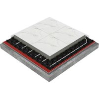
VLo Nexxa-12 - Underfloor heating Warmup - Free user manual and instructions
Find the device manual for free VLo Nexxa-12 Warmup in PDF.


| Product Type | Programmable Thermostat for Electric Underfloor Heating |
| Model | VLo Nexxa-12 |
| Brand | Warmup |
| Dimensions (H x W x D) | 86 x 86 x 30 mm |
| Weight | Approx. 150 g |
| Power Supply | 230 V AC, 50/60 Hz |
| Maximum Load | 16 A (resistive) / 3680 W |
| Display | Touchscreen LCD with backlight |
| Programming | 7-day programmable with up to 6 time periods per day |
| Temperature Range | 5°C to 35°C (floor and air sensing modes) |
| Sensor Type | Built-in air sensor and floor sensor (NTC 10k) |
| Communication | Wi-Fi (2.4 GHz) for app control and smart home integration |
| Compatibility | Electric underfloor heating systems, compatible with Warmup mats and cables |
| Energy Saving | Adaptive start, open window detection, and geofencing via app |
| Installation | Surface mount (with optional flush mount kit) |
| Protection Rating | IP21 (indoor use only) |
| Material | White ABS plastic, scratch-resistant glass panel |
| Warranty | 3 years |
| Certification | CE, UKCA, RoHS |
Frequently Asked Questions - VLo Nexxa-12 Warmup
User questions about VLo Nexxa-12 Warmup
0 question about this device. Answer the ones you know or ask your own.
Ask a new question about this device
Download the instructions for your Underfloor heating in PDF format for free! Find your manual VLo Nexxa-12 - Warmup and take your electronic device back in hand. On this page are published all the documents necessary for the use of your device. VLo Nexxa-12 by Warmup.
USER MANUAL VLo Nexxa-12 Warmup
SAFETY Net Installation-Guarantee

Warmup®
The world's best-selling floor heating brand™
Over 2.5 million installations in more than 72 countries
Experience MyHeating™
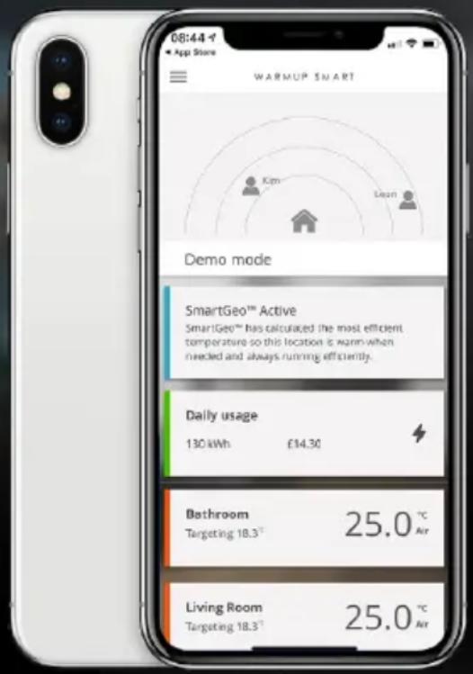

SmartGeo™
Unique SmartGeo™ automatically turns down the heating when you're out.

Easy to use
Simple and secure setup using WiFi, with 24/7 technical support.

AutoSwitch™
Always on the best tariff, automatically. Reduce energy bills by over £400
Download now for iOS and Android

Available on the App Store


GET IT ON Google Play

GE DBWE Thermostat

www.warmup.co.uk
Quick install guide....4
Components available from Warmup....6
Important installation information....7
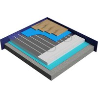
Typical floor build-up....8
Step 1 - Subfloor considerations....9
Step 2 - Installing VLo Nexxa-12....10
Step 3 - Lay the pipe 12
Step 4 - Lay levelling compound .... 14
Troubleshooting....15
Warranty 16
Technical specifications.... 18
System Performance....19
Your Warmup ® underfloor heating system has been designed so that installation is quick and straight forward, but it is important that the instructions in this manual are followed to ensure that your underfloor heating system performs correctly. Please ensure that you have the components and working drawings necessary for this system before you begin installation.
Warmup plc, accepts no liability, expressed or implied, for any loss or consequential damage suffered as a result of installations which in any way contravene the instructions that follow.
It is important that before, during and after installation that all requirements are met and understood. If the instructions are followed, you should have no problems. If you require help at any stage, please contact our helpline.
You may also find a copy of this manual, wiring instructions and other helpful information on our website
www.warmup.co.uk
Please also read the full instructions that follow this section.
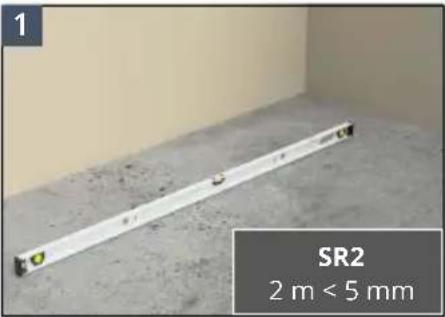
- The subfloor must be pre-insulated unless it is an intermediate floor.
Ensure the subfloor is prepared to an SR2 Surface Regularity.

- The subfloor must be smooth, dry, frost-free, solid, suitably weight-bearing and dimensionally stable.
Referring to its instructions, prime the subfloor and the bottom 30 mm of adjacent walls using Warmup Primer.

• Install Warmup perimeter strip around the perimeter of the floor and any penetrations to allow for expansion and contraction of the floor.

- Cut membrane to size as required, peel back the release film and tack into place. Once correctly positioned, press down firmly.
Lay additional sheets overlapping the outer row of smaller castellations to create a continuous layer.

- Lay the pipe in a spiral configuration, pressing it into the castellations of the membrane.
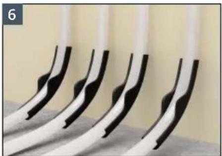
- Use Warmup Pipe Bend Supports where the pipe exits the floor at the manifold location.
• Refer to the manifold manual for detailed information on mounting, calibration and pressure testing.

• Measure and cut the pipe so that it reaches both the flow and return ports on the manifold.

- Following the levelling compound instructions, apply a 22 mm layer of Warmup levelling compound over the membrane.
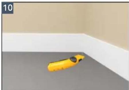
- The 30 mm tall perimeter strip should finish just proud of the levelling compound but can be trimmed back flush with a utility knife if required.
The 22 mm layer is measured from the base of the membrane.
- The floor finish can be installed once the levelling compound has cured and dried.

• Install your Warmup thermostat referring to their installation instructions.
Product Code Description
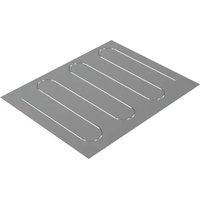
RNX-PANEL Nexxa-12 membrane
PERT-12x70 Warmup PE-RT pipe 12 mm
Additional components that may be required as part of your Warmup heating installation:
Compatible levelling compound
Manifold, mixing unit, actuators, valves and euroconus connectors
Wiring centre
Warmup thermostats
Warmup Ultralight
i Perform a site inspection. You will need to confirm that all measurements and other requirements on site match your working drawings.
i Inspect the site for possible hazards that could damage the Warmup pipe, such as nails, staples, materials or tools.
i Ensure that all subfloors are at the depth needed to incorporate the underfloor heating.
The subfloor must be pre-insulated unless it is an intermediate floor. Ensure the subfloor is prepared to an SR2 Surface Regularity. The subfloor must be smooth, dry, frost-free, solid, suitably weight-bearing and dimensionally stable.
i Ensure levelling compound used is compatible with underfloor heating and suitable for application onto plastic underlayments such as the Nexxa-12 membrane. The levelling compound must be applied as a single layer.
Before installing the floor finish, its suitability for use with underfloor heating and its maximum operating temperature should be checked against required operating conditions.
Use a pipe cutter designed for plastic pipe ensuring that there are no burrs on the pipe ends. It is important to achieve a clean cut.
Do not pull pipe from the coil while it is sitting flat. It must be unwound from the coil, rotating the coil as the pipe is pulled from the inside.
Do not force the pipe into bends. It is easier to lay the pipe with a large radius and then gently pull the pipe to the required bend. The minimum bending radius is 5 times the diameter of the pipe.
Do not kink the pipe. Excessive bending of the pipe can cause it to kink, where this occurs flow may be obstructed or reduced. Kinked pipe must be repaired or replaced. To repair a kink, straighten the pipe and simply heat the area with a hot air gun until the kink disappears.
i Underfloor heating performs the most efficiently with conductive, low resistance floor finishes such as stone and tiles. Consideration should be given to the thermal resistance and temperature limits of the chosen floor covering and its impact on the system heat output.
| All floor finishes | |
| 1 | Warmup perimeter strip |
| 2 | Floor finish |
| 3 | 22 mm levelling compound The 22 mm layer is measured from the base of the membrane. Levelling compound used must be compatible with plastic underlayments such as Nexxa-12. The levelling compound must be applied as a single layer. |
| 4 | Floor sensor Tab tape the sensor to the membrane. Do not tape over the sensor tip! |
| 5 | Nexxa-12 membrane |
| 6 | Warmup Ultralight (Optional) Adding Warmup Ultralight below the membrane can help improve the response time of the system, particularly when installing over screed or concrete. |
| 7 | Flexible tile adhesive (Optional) Required if installing Warmup Ultralight |
| 8 | Warmup primer Refer to tile adhesive manufacturers instructions for priming requirements |
| 9 | Subfloor with a surface regularity of SR2* |
| * If installing the optional Warmup Ultralight, refer to its installation manual for its sub floor requirements. | |
To prevent excessive heat loss through the floor, Nexxa-12 may only be laid over insulated or intermediate subfloors.
The subfloor must be solid, structurally sound and dimensionally stable. It must be suitably weight-bearing when accounting for the additional load of the system.
Ensure the subfloor is prepared to an SR2 Surface Regularity. If necessary an appropriate smoothing or levelling compound should be applied.
The surface Nexxa-12 is being applied to must be smooth and primed with Warmup Primer such that a clean and continuous bond can be made. Warmup Primer requires than the subfloor is dry, frost-free, solid, weight-bearing and dimensionally stable. It must be free from contaminants that may impede adhesion such as dust, dirt, oil, grease, release agents, loose material or surface laitance.
If installing Nexxa-12 over Warmup Ultralight, the surface of the Ultralight does not need priming if it is kept clean.
i Where ceramic tiles are to be used, ensure that the subfloor meets the Tile Associations minimum specifications.
Do not commence installation of Nexxa-12 without ensuring that the resulting floor construction will meet the requirements of the floors intended use and its finish.
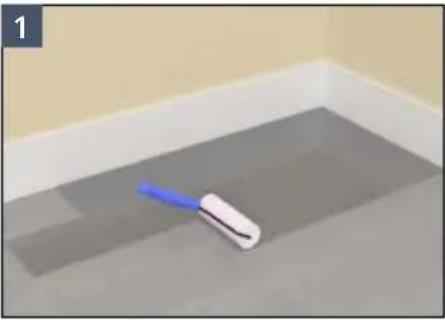
• The subfloor must be pre-insulated unless it is an intermediate floor.
Ensure the subfloor is prepared to an SR2 Surface Regularity. The subfloor must be smooth, dry, frost-free, solid, suitably weight-bearing and dimensionally stable.
Referring to its instructions, prime the subfloor and the bottom 30 mm of adjacent walls using Warmup Primer.
- If installing Warmup® Ultralight over the subfloor please refer to its installation instructions. Ultralight will help reduce the heat up times of your system for optimal performance. The surface of Ultralight does not require priming.

• Install Warmup Perimeter Strip around the perimeter of the floor and any penetrations to allow for expansion and contraction of the floor.
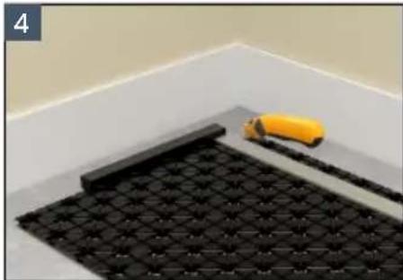
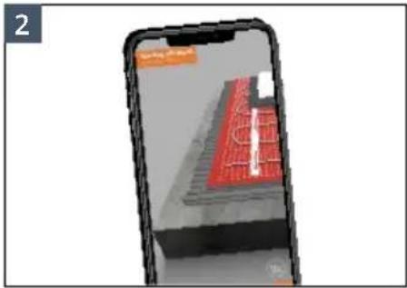
- Where cuts are required, turn the Nexxa-12 upside down and cut using a utility knife and a straight edge.
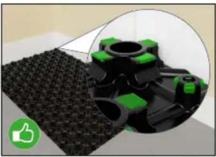
- When placing the first sheet of Nexxa-12 membrane, position its corner which has the large castellation, into the chosen corner of the room.
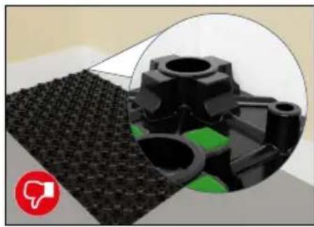
- The opposing corner has a slightly smaller castellation with no overhangs, this allows subsequent sheets to overlap and interlock with preceding sheets.
This smaller castellation must not be positioned into the corner to start!

- Once cut to the correct size, peel back the release film from one corner and tack in place.
Once correctly positioned remove the release film entirely and press down firmly to attain a secure bond.

- Maintain this orientation for all subsequent sheets within the room, laying them such that they overlap the outer row of smaller castellations and create a continuous layer.
If the project has been supplied with a set of working drawings, follow the provided pipe layout. Ensure each circuits details are recorded in the commissioning log provided in the Warmup Manifolds installation manual.

- Plan the circuit layout ensuring that the flow and return pipes can connect from the manifold to their respective heated area without crossing each other and to minimize instances where the pipe passes through expansion joints.

- Any expansion joints present in the sub floor must be continued through the Nexxa-12 installation layer.
Pipes that cross expansion joints must be straight and perpendicular to the joints. The straight section must have a length of conduit 600 mm long centered on the expansion joint to allow for movement.
i Feed pipes normally go through doorways but to minimise congestion, pipes can be fed through walls. Ensure holes drilled in the wall are at floor level and the pipe is protected with a conduit.

- Begin installing the pipe from the manifold location. Leave excess pipe at the manifold location which can be cut later after the pipe has been laid.

- Use Warmup Pipe Bend Supports where the pipe exits the floor at the manifold location.
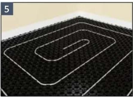
- The pipe should be laid in a spiral configuration. The first loop should be laid around the perimeter of the room, then working inwards towards the centre at double the intended pipe spacings.

- Once you reach the centre work back out, completing the spiral at the intended pipe spacing.
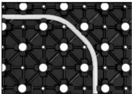
- 90° bend

- 180° bend

- When negotiating obstacles it may be necessary to temporarily tighten pipe spacings.
To make staggering the pipe easier, crush or remove the small castellation obstructing the pipe path.

Levelling compound used must be compatible with plastic underlayments such as Nexxa-12. The levelling compound must be applied as a single layer.

- Ensure the membrane is clear of debris before laying the levelling compound.

- Apply a 22 mm layer of Warmup levelling compound over the membrane. The 22 mm layer is measured from the base of the membrane.
Refer to the levelling compound instructions for mixing, drying and curing information.
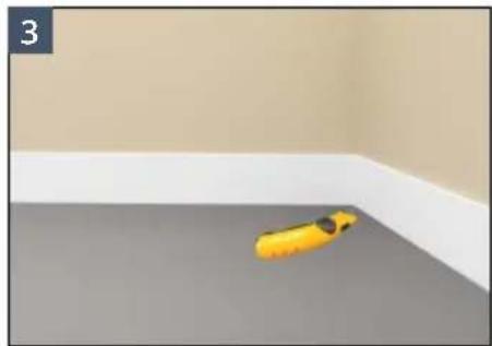
- The 30 mm tall perimeter strip should finish just proud of the levelling compound but can be trimmed back flush with a utility knife if required.

- Lay the floor covering adhering to the flooring manufacturers instructions.
Ensure any floor coverings, underlays and adhesives used are suitable for use with underfloor heating at the intended operational temperatures and conditions.
| ISSUE 1 - Membrane not sticking to the subfloor | |
| PROBLEM SOLUTION | |
| The subfloor is likely damp, dusty, coarse or contaminated with another substance preventing proper adhesion. | Ensure the subfloor is prepared in accordance with this manual. |
| ISSUE 2 - Cracked tiles or leveller | |
| PROBLEM SOLUTION | |
| Timber Subfloor - There is excessive movement in the subfloor causing the floor to flex leading to cracked tiles | The issue with the subfloor has to be resolved otherwise the tiles will continue to crack |
| Leveller used is not suitable for application or not mixed as per its instructions | The levelling compound used needs to be able to be 22 mm thick and suitable for plastic underlayments |

Each mat and sensor must be tested before they are installed, once they have been laid but before tiling or laying levelling compound and again before they are connected to the thermostat. The resistance (ohms) should be measured and recorded in the control card at the end of the manual.

Due to the high resistance of the heating element, it may not be possible to get a continuity reading from the heating cable and as such, continuity testers are not an acceptable substitution for testing. When checking resistance, make sure your hands do not touch the meter's probes as the measurement will include your internal body resistance and render the measurement inaccurate. If you do not get the expected results or at any time you believe there may be a problem, please contact Warmup for guidance.
Mat resistance test Earth fault test

- Set a multimeter or ohmmeter to record resistance in the range of 0-500 Ω. Measure the resistance across the live (brown) and neutral (blue) wires. Ensure the measured resistance is within the Reference Resistance Band for the cable size being tested
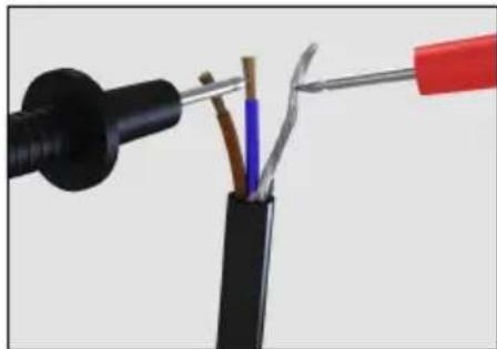
- Set a multimeter or ohmmeter to record resistance in the range of 1 MΩ or greater if available. Measure the resistance across the live (brown) and neutral (blue) wires to the earth braid.
Ensure the measured resistance is showing as greater than 500 MΩ or infinite if the meter cannot read this high.
Sensor resistance test

- Ensure that the sensor is tested before the final finish has been fitted. Warmup thermostats typically use a 10 kΩ sensor. Please to refer to the thermostat manual for further details.
The expected resistance depending on temperature is listed below.
Sensor resistance by temperature - NTC10K
| Temperature Resistance Temperature Resistance |
| 0 °C 32.5 kΩ 16 °C 15.0 kΩ |
| 2 °C 29.4 kΩ 18 °C 13.7 kΩ |
| 4 °C 26.6 kΩ 20 °C 12.5 kΩ |
| 6 °C 24.1 kΩ 22 °C 11.4 kΩ |
| 8 °C 21.9 kΩ 24 °C 10.5 kΩ |
| 10 °C 19.9 kΩ 26 °C 9.6 kΩ |
| 12 °C 18.1 kΩ 28 °C 8.8 kΩ |
| 14 °C 16.5 kΩ 30 °C 8.1 kΩ |
Warmup plc limited warranty - Hydronic floor heating pipe

Registration can be completed online at www.warmup.co.uk.
In the event of a claim, proof of purchase is required in the form of an invoice or receipt.
THIS WARRANTY DOES NOT EXTEND TO OTHER COMPONENTS WHICH ARE COVERED BY SEPARATE WARRANTIES. THIS WARRANTY DOES NOT AFFECT YOUR STATUTORY RIGHTS.
Limited warranty:
Warmup® underfloor heating pipe is warranted by Warmup plc ("Warmup") to be free from defects in manufacturing under normal use and maintenance, and is warranted to remain so subject to the limitations and conditions described below.
This warranty period begins on the date of purchase. The Lifetime warranty only applies if the product is registered with Warmup within 30 days after purchase and registered online at www.warmup.co.uk. Registration is confirmed only when confirmation of receipt is forwarded by Warmup plc
Warranty duration
- The PE-RT underfloor heating pipe is warranted for the LIFETIME of the floor under which it is fitted, except as provided below; your attention is drawn to the exclusions listed and the end of this warranty.
Notification of a suspected failure must be received in writing by Warmup within thirty (30) days of the suspected failure. Products believed to be defective must be made available to Warmup for testing and determination of cause.
Upon acceptance of any warranty claim, Warmup shall have ninety (90) business days in which to investigate and determine whether it recognises responsibility for any believed defects in material or workmanship and determines the appropriate course of action to be taken.
It is expressly agreed that the sole remedies under this limited warranty shall be at the discretion of Warmup, plc to either: issue a refund, repair or replace any article which is proven to be defective. Any and all allowances made to customers for transportation, labour, repairs or all other work, are at the exclusive discretion of Warmup and shall be authorised in writing, in advance, by Warmup. Such cost does not extend to any cost other than direct costs of repair or replacement by Warmup and does not extend to costs of relaying or repairing any floor covering or floor.
The lifetime warranty applies to the pipes(s) if they:
- Are registered with Warmup within 30 days after purchase.
- Have not operated at a pressure of greater than 8 Bar.
- Have not operated at a temperature of greater than 60° C.
- Are filled with treated water subtitle for use with PE pipes.
- Are installed according to all applicable building code requirements.
- Are selected, designed and installed by a qualified contractor according to installation instructions provided by Warmup which are current as of the applicable installation date.
- Remain in their original installed location, such that the floor covering or screed over the product is not damaged, lifted, replaced, repaired or covered with subsequent layers of flooring.
- Do not show evidence of accidental damage, misuse, lack of care, tampering, or repair or modification without the prior written approval of Warmup plc.

SafetyNet™ Installation Guidelines: If you make a mistake and damage the pipe before covering the pipe with screed, levelling compound or floor covering, return the damaged pipe to Warmup within in 30 days along with your original dated sales receipt. WARMUP WILL REPLACE THE COIL OF PIPE (MAXIMUM 1 COIL OF PIPE PER ORDER) WITH ANOTHER COIL OF THE SAME MAKE AND MODEL - FREE.
Register your Warmup® warranty online at www.warmup.co.uk
(i) Pipes repaired by Warmup carry a 5 year warranty only. Under no circumstances is Warmup responsible for the repair or replacement of any tiles / floor covering which may be removed or damaged in order to affect the repair.
(ii) The SafetyNet™ Installation Guarantee is null and void once the pipe is covered with a screed, levelling compound, adhesive or floor deck.
(iii) Damage to the pipe that occurs after covering, such as lifting a damaged tile once adhesive has set, or subfloor movement causing floor damage, is not covered by the SafetyNet™ Guarantee.
Nexxa-12 membrane
Product code RNX-PANEL
Dimensions 16 x 650 x 1050 mm
Effective dimensions 16 x 600 x 1000 mm / 0.60 m²
Installation height 22 mm (with levelling compound)
Pipe spacing increments
50 mm (alternating 43 mm / 70 mm on the diagonal)
Pipe orientation 0 / 90 / +45 / - 45°
Pipe bend radius 75 mm
Single row stagger
Yes
(crush/remove small castellation first)
Supported pipe diameters 10 - 12mm
| kH Value - W/ m2K | |||||||||||||||
| Resistance of Floor Covering, tog | 0.00 | 0.25 | 0.50 | 0.75 | 1.00 | 1.25 | 1.50 | 1.75 | 2.00 | 2.25 | 2.50 | 2.75 | 3.00 | ||
| 100mm Pipe Centres | 8.56 | 6.95 | 5.85 | 5.05 | 4.44 | 3.96 | 3.58 | 3.26 | 2.99 | 2.77 | 2.57 | 2.41 | 2.26 | ||
| 150mm Pipe Centres | 7.15 | 5.91 | 5.05 | 4.41 | 3.91 | 3.52 | 3.21 | 2.94 | 2.72 | 2.53 | 2.36 | 2.21 | 2.09 | ||
| q = Specific Heat Output, W/m2k | H = System Performance Factor, W/m2K |
| Twater = Mean water Temperature T | air = Room Air Temperature |
Using the system kH value to calculate the system heat output:
q = k _ H × (T _ water - T _ air )
Example:
The heat output through an 18mm thick, ≈ 1.25 tog timber floor, over Nexxa-12 fitted with pipe at 150mm centres, in a 21°C room heated with 40°C is;
q = 3. 5 2 × (4 0 - 2 1) = 3. 5 2 × 1 9 = 6 7 W / m ^ 2
Alternatively, using the system kH value to calculate the required water temperature, knowing the required heat output:
T _ water = (q / k _ H) + T _ air
Example:
The water temperature required to produce a heat output of 55W/m², through a 3mm thick ≈ 0.25 tog LVT floor finish, over Nexxa-12 fitted with pipe at 100mm centres, in a 22°C room is;
T _ water = (5 5 / 6. 9 5) + 2 2 = 7. 9 + 2 2 ≈ 3 0 ^ ° C
Floor sensor setting for target heat output

The room with the highest water temperature requirement sets the design water temperature for the whole system based on the calculations from the previous section.
Using the graph above it is possible to limit the specific heat output to the required value.
The example above shows a design room air temperature of 20° C and design heat output of 52.5 W/m2 . Based on a 0.150 m2 K/W (1.5 tog) floor finish the floor sensor should be set to 33° C ( 20° C room air + 13° C ΔT ) to resulting in floor surface temperature of 25° C ( 20° C room air + 5° C ΔT ).

Specific Heat Output, W/m²

The design floor surface temperature difference should not be more than 9 °C in occupied areas, 15 °C in unoccupied areas.

Heat output is limited by the floor finish resistance combined with the maximum probe setting of 40 °C.

Temperature limits of the floor finish or its adhesive may adversely limit the design heat output.

Warmup plc
www.warmup.co.uk
uk@warmup.com
Tel: 0345 345 2288
Fax: 0345 345 2299


Please scan the QR code to provide feedback on your installation

- WARMUP®
- OVER 2.5 MILLION INSTALLATIONS IN MORE THAN 72 COUNTRIES
- EXPERIENCE MYHEATING™
- SMARTGEO™
- EASY TO USE
- AUTOSWITCH™
- DOWNLOAD NOW FOR IOS AND ANDROID
- PRODUCT CODE DESCRIPTION
- ADDITIONAL COMPONENTS THAT MAY BE REQUIRED AS PART OF YOUR WARMUP HEATING INSTALLATION
- WARMUP PLC LIMITED WARRANTY - HYDRONIC FLOOR HEATING PIPE
- LIMITED WARRANTY
- WARRANTY DURATION
- THE LIFETIME WARRANTY APPLIES TO THE PIPES(S) IF THEY
- REGISTER YOUR WARMUP® WARRANTY ONLINE AT WWW.WARMUP.CO.UK
- NEXXA-12 MEMBRANE
- EXAMPLE
- WARMUP PLC
Brand : Warmup
Model : VLo Nexxa-12
Category : Underfloor heating