
CI6 Ð 100V - Loudspeaker MARTIN - Free user manual and instructions
Find the device manual for free CI6 Ð 100V MARTIN in PDF.


| Product Type | Fog Machine |
| Brand | Martin |
| Model | CI6 Ð 100V |
| Power Supply | 100 V AC, 50/60 Hz |
| Power Consumption | 1000 W |
| Dimensions (L x W x H) | 500 x 300 x 300 mm |
| Weight | 10 kg |
| Fluid Capacity | 2.5 L |
| Heater Type | Stainless steel heat exchanger |
| Warm-Up Time | Approx. 5 minutes |
| Output (Fog Volume) | Up to 500 m³/min |
| Control Options | Manual, DMX, remote control |
| DMX Channels | 1 or 2 |
| Compatible Fluids | Martin Fog Fluid (water-based) |
| Safety Features | Thermal cut-out, low fluid indicator |
| Cleaning | Use distilled water or cleaning solution after each use |
| Repairability | Replaceable heater and pump; service available |
| Certifications | CE, ETL |
| Operating Temperature | 0°C to 40°C |
Frequently Asked Questions - CI6 Ð 100V MARTIN
User questions about CI6 Ð 100V MARTIN
0 question about this device. Answer the ones you know or ask your own.
Ask a new question about this device
Download the instructions for your Loudspeaker in PDF format for free! Find your manual CI6 Ð 100V - MARTIN and take your electronic device back in hand. On this page are published all the documents necessary for the use of your device. CI6 Ð 100V by MARTIN.
USER MANUAL CI6 Ð 100V MARTIN
Please read this manual carefully before attempting to install the product.
Every effort has been made to ensure that the contents of this manual are correct. Mach Speakers A/S does not accept any liability for loss or damage caused or alleged to be caused directly or indirectly by this manual. The contents of the manual may be subject to change without notice. Mach Speakers A/S makes no warranty of any kind with regards to this material.
Copyright 2005 Mach Speakers A/S
Reproduction in any matter whatsoever without the written permission of Mach Speakers A/S is strictly forbidden.
Mach Speakers A/S • Perspektivvej 2 • 9900 Frederikshavn • Denmark Tel: +45 72 15 08 52 • Fax: +45 98 43 14 15 • e-mail: Mach-Service@martin.dk
Table of contents
Introduction 3
The CI series 4
Included items 5
Description of CI speakers 6
CI4, 6 and 8 6
Mounting bracket 7
CIW Subwoofer
How to install your CI speaker 9
Auxiliary mounting bracket 12
Mounting speaker on bracket 13
How to insert speaker cable 13
How to attach safety wire 14
Connecting to amplifier 15
Simple connection 15
Parallel system 16
Serial system 17
100V lines 18-19
Maintenance of speakers 20
Warranty 20
Technical information 21
CI4 21
CI6 22
CI8 23
Troubleshooting 24
Ordering spare parts 25
8
Introduction
Thank you for purchasing a product from Mach Speakers A/S. Every effort has been made to ensure that our products fulfil your demands and we sincerely hope that we will live up to your expectations.
To get the most out of your Mach speakers and ensure an easy, trouble-free installation, please read the manual carefully and follow the instructions.
If you have any additional questions or comments please do not hesitate to contact our headquarters in Denmark at the following address:
Mach Speakers A/S
Perspektivvej 2
DK-9900 Frederikshavn
Denmark
Tel: (+45) 72150852
Or send an e-mail to: machservice&support@martin.dk
The CI series
The CI series has been designed specifically for contractors as a high quality, ultra-flexible solution with all necessary brackets included in one convenient package.
The CI4, 6 and 8 are all 8 ohm two-way speakers with a horn with uniform dispersion for very flexible positioning. The cabinets have been shaped to achieve both an appealing and attractive appearance and very easy mounting.
Special care has been taken to ensure that a minimum of tools are required for mounting and adjusting the speakers. In fact, once the bracket has been screwed to the wall no other tools are required, either for mounting the speaker on the bracket or for adjusting the speaker horizontally and vertically.
The CI series has been designed for commercial venues such as cafés, clubs, department stores, conference rooms and hotels that require high fidelity in-fill sound.
The goal of the in-fill speaker design is to provide hi-fi performance with high speech intelligibility in a compact package. As background noise in these venues is typically located in the mid-frequency area, the in-fill speakers are acoustically optimized for clarity and openness in the mid-range.
The CI4 and CI6 are top-boxes that can be supported by the CIW subwoofer or the bass output of the venue's main PA system. However, in environments with reduced demands for sound pressure they can also be used as stand-alone systems.
The CI8 is a full range speaker with usable bass output down to 60Hz and can therefore be used as a stand-alone system in a wide range of applications.
The CIW is the perfect subwoofer supplement for the CI4, 6 and 8. It has an integrated high-pass filter that enables the sub and two top-boxes to be powered by one amplifier.
All Mach CI in-fill speakers have wide, even dispersion that ensures good coverage in low-ceiling applications.
Contents of the box
The Mach CI speaker is supplied as a complete system and your sales package should contain the following items:

2 Speakers

2 Wall hanging brackets

2 Auxiliary mounting brackets

2 Safety wires

2 Safety screws

8 Wall screws

8 Rawlplugs

1 Manual

Description of CI speakers
CI4, 6 and 8
The cabinet for the CI4, 6 and 8 speakers is made of ABS plastic to achieve the right combination of strength, functionality and design. The drawing below shows the functional features of the cabinet.
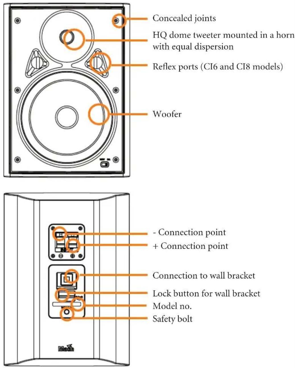
Concealed joints
HQ dome tweeter mounted in a horn with equal dispersion
Reflex ports (CI6 and CI8 models)
Woofer
- Connection point
+ Connection point
Connection to wall bracket
Lock button for wall bracket
Model no.
Safety bolt
Mounting bracket
The CI series is supplied with a unique Mach TF mounting bracket that enables horizontal and vertical adjustment without the use of tools. The Mach TF bracket is illustrated below
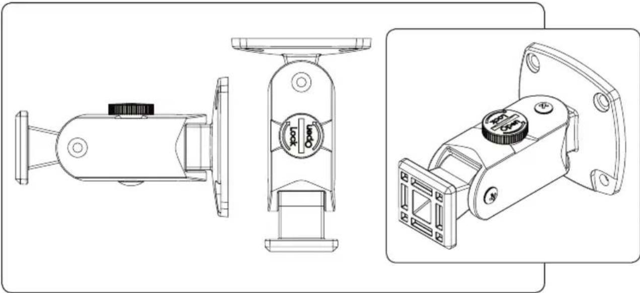
To adjust the bracket, loosen the round locking knob on the top of the bracket by turning counterclockwise, and adjust to the desired horizontal and vertical position. Tighten the locking knob and the bracket will be fixed in position as illustrated below:

CIW subwoofer
The CIW subwoofer is constructed as the perfect supplement for the CI4, 6 and 8 speakers. The CIW has an amazing low-end sound quality unmatched by any other competing subwoofer product and the unique cabinet construction enables easy, flexible installation.

How to install your CI speaker
How to mount the bracket on the wall
To mount the Mach TF bracket on a wall:
- Find the correct position on the wall and mark where the base of the bracket should be positioned.
- Take the bracket and hold the base flat to the wall at the marked position. Note: the locking button must point upward for correct positioning.
- Mark each hole with a marking tool or a pencil.
- Remove the bracket.
- If using the supplied rawlplugs, drill four holes 40 mm deep using a 6 mm masonry drill.
- Insert a rawlplug into each hole.
- Position the bracket so that the mounting holes align with the holes in the wall. Note that one corner has a recess for the safety wire.
- Screw the corner og the bracket opposite to the safety wire recess loosely to the wall.
- Insert the end loop of the safety wire into recess, push a screw through the hole and tighten loosely.
- Align the bracket horizontally. Insert the last two screws and tighten all 4 screws appropriately.
The bracket has been designed to carry a speaker no larger than the CI8 weighing no more than 6 kg(13.2 lbs)

Mark each hole with a marking tool or a pencil
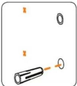
If using the supplied rawlplugs, drill four holes 40 mm deep using a 6 mm masonry drill.

Insert the end loop of the safety wire into its recess, push a screw through the hole and tighten loosely.
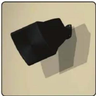
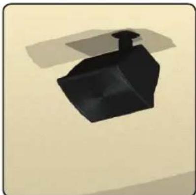
The Mach TF bracket is extremely versatile and can be used for mounting the speaker in most of the required positions as illustrated.

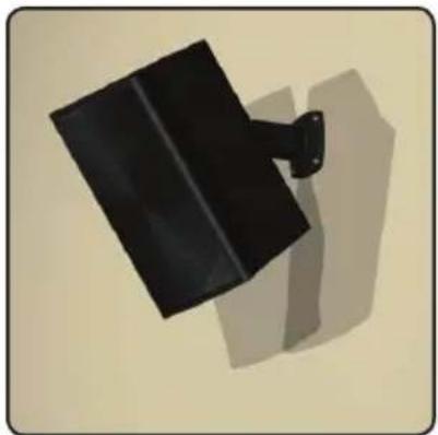

Wall mounting Outdoor wall mounting

Ceiling mounting
Ceiling mounting

Mounting on pole

Table

[Non-Text]

Mounting on poleTable
Auxiliary mounting bracket
For rare situations where the Mach TF bracket will not be suitable for mounting the speaker, the CI series is also supplied with an auxiliary mounting bracket. This bracket can still use the built-in quick release system in the speaker cabinet, but can be connected to any alternative type of wall bracket.

Mounting speaker on bracket
To mount the speaker on the Mach TF bracket, insert one side of the Mach TF end square into the speaker locking plate, press the locking button down and insert the other side of the end square. Once the end square is completely inside the locking plate, release the locking button and make sure that the end square is now locked tightly into place.

How to insert speaker cable
To insert the speaker cable press down on the two terminal buttons and insert the cable ends. Release the buttons to lock the cable in place.

The speaker cable can be aligned along the back of the speaker and secured to the safety wire with a cable strap.
How to attach safety wire
The safety wire is attached to the speaker at one end and the wall at the other. To attach the safety wire to the speaker, please screw the fastener screw tightly into the speaker cabinet.

Connecting to an amplifier
The way you connect your CI speakers to your amplifier depends on the type of installation that you are creating and the type of amplifier used.
Simple connection
The most basic type of connection is a direct connection from one channel on the amplifier to one speaker. In this case connect the [+] terminal on the amplifier to the [+] terminal on the speaker and the [-] terminal on the amplifier to the [-] terminal on the speaker.
Warning! Always check the amplifier manual to ensure that the loading of your speakers in serial or parallel connection complies with the amplifier specifications.

Parallel system
If you require more speakers for better sound distribution and you only have a limited number of output channels on your amplifier, you can connect more than one speaker to each channel. This can be done by linking the speakers for each channel in parallel as illustrated. However, always remember to check the minimum loading impedance specified for the amplifier. The max number of CI speakers that can be connected to each amplifier channel is calculated as follows: the impedance of the speaker (8 ohms for the CI series) divided by the min. specified impedance for the amplifier (often 4 ohms).
![graph TD A["Amplifier"] -->|main.| B["Output"] A -->|main.| C["Input"] A -->|4 ohm 4 ohm| D["Right"] A -->|8 ohm 8 ohm| E["Left"] D --> F["Four 4 ports"] E --> G["Four 8 ports"]](/content/2026/05/1094733/images/7de9239652ebd009688ad359ae1c5988c86b73fa61f4ee702d1c8d2e5b57904c.jpg)
Serial system
If the amplifier has a minimum impedance of 8 ohms it is still possible to connect more than one speaker to each channel by using serial connection. When using serial connection, however, please remember that the output will drop according to the number of speakers attached to each channel.
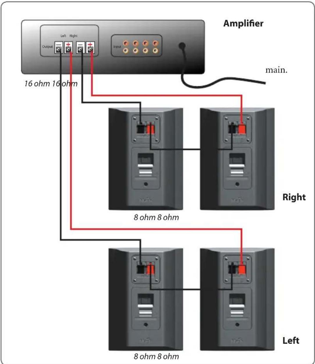
Warning! Always follow the amplifier instructions when connecting your speakers. A faulty setup can damage your amplifier and have a serious negative impact on the sound quality.
100V lines
It is usual in public addres system installations to find that the signal has to travel over considerable distances. Logically, this is due to the fact that the speakers are separated from the source and also due to the large number of speakers that are sometimes used. There are some matters that we should bear in mind if we want to guarantee a successful installation.
When the distances are considerable, the cable's own ohmic resistance will absorb part of the line energy. We could say that the power in the change (speaker) will be altered by the least energy provided by the amplifier as there is a greater impedance in the output terminals.
A possible solution could be to increase the section of the conductor, but this would not be viable if the distances are considerable or multiple connections are used, as costs would be high.
The Solution is to increase the impedance in the speaker terminals with the consequent increase in the nominal line voltage in order to maintain the required values.
Public address system amplifiers adapt their output through transformers. Nominal voltage is generally 100 volts, although sometimes it may be 50 or 70 volts.
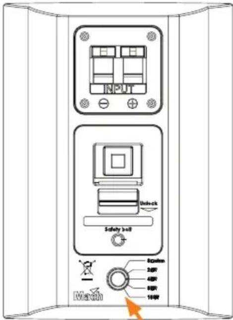
100V switch.
8 ohm, 2w, 4w, 8w, 16w.
As we know the standard impedance of the speakers, we need to incorporate impedance transformers. Adapting the primary to the line and the secondary to the speaker allows the multiple connection of elements.
Installing them is very simple. They are parallel connected and sp each sound output can be independently regulated and in case of an individuel fault the whole system will not be affected.
2-16W parallel system
![graph TD A["main."] --> B["100V Amplifier"] B --> C["Output"] B --> D["Left"] B --> E["Right"] B --> F["Input"] C --> G["Chamber 1"] C --> H["Chamber 2"] C --> I["Chamber 3"] C --> J["Chamber 4"] C --> K["Chamber 5"] C --> L["Chamber 6"] D --> M["Chamber 1"] D --> N["Chamber 2"] D --> O["Chamber 3"]…](/content/2026/05/1094733/images/0a751607452461a7834a46790f154b85613b241c6508134b1e1eb1c97627f48a.jpg)
Warning! Always follow the amplifier instructions when connecting your speakers. A faulty setup can damage your amplifier and have a serious negative impact on the sound quality.
Maintenance of speakers
Even though speaker systems normally only require very limited maintenance there are several things that you can do to ensure that your Mach system will sound as good 3 years after installation as on the day you bought it:
Never overload your system but stay within the specified limits for power handling.
Always keep the speaker clean and dry.
Even though the CI series is built to be weather resistant, the speakers are not able to withstand prolonged exposure to water. Over time, dust and dirt will also not only reduce the quality of the sound but can ruin the tweeter and woofer membranes.
As with any electrical product, currents will accelerate corrosion of metal surfaces. Therefore, it is recommended to check the terminals for corrosion at regular intervals, especially if the speaker is mounted in a hostile environment.
Warranty
For information on the warranty conditions specific to your country please refer to the material handed to you by your local Mach distributor.
Technical information
CI 4

Specifications:
Power rating IEC258 50W
Power rating peak 200W
Recommended amplifier 70W
Freq. Range +/-3dB 120Hz-20KHz
Freq. Range +/-10dB 80Hz-20KHz
Sensitivity 1W/1m 87dB
Nominal impedance 8 ohm
Woofer 4"
Tweeter 3/4"
Dispersion 90°
Flying system TF bracket, Aux mounting bracket
Dimensions (H x W x D) 207x150x120mm
(8.15x5.91x4.72in)
Net weight 1.8 Kg (4 lbs)
Cl 6
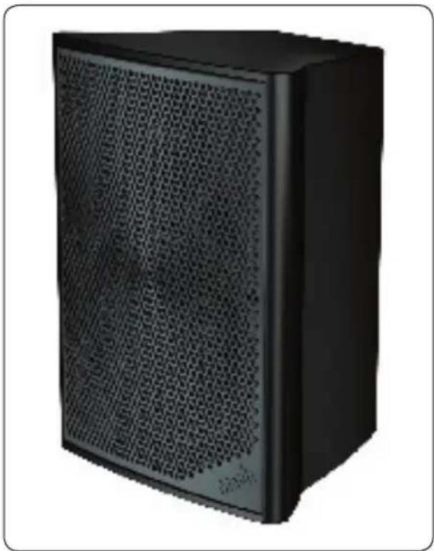
Specifications:
Power rating IEC258 65W
Power rating peak 260W
Recommended amplifier 100W
Freq. Range +/-3dB 90Hz-20KHz
Freq. Range +/-10dB 70Hz-20KHz
Sensitivity 1W/1m 89dB
Nominal impedance 8 ohm
Woofer 6.5"
Tweeter 3/4"
Dispersion 90°
Flying system TF bracket, Aux mounting bracket
Dimensions (H x W x D) 275x200x160mm
(10.83x7.83x6.30in)
Net weight 2.7 Kg (5.9 lbs)
Cl 8

Specifications:
Power rating IEC258 125W
Power rating peak 500W
Recommended amplifier 175W
Freq. Range +/-3dB 70Hz-20KHz
Freq. Range +/-10dB 60Hz-20KHz
Sensitivity 1W/1m 93dB
Nominal impedance 8 ohm
Woofer 8"
Tweeter 1"
Dispersion 90°
Flying system TF bracket, Aux mounting bracket
Dimensions (H x W x D) 395x290x220mm
(15.55x11.42x8.66in)
Net weight 5.2 Kg (11.5 lbs)
Troubleshooting
Installing a Mach professional speaker system should be problem-free. However, installation errors or amplifier faults can impair sound quality.
If cables are not connected in phase, or if connections are bad, you may experience lack of bass due to phase cancellation or no sound at all. All cables must be connected positive to positive, negative to negative.
The speakers have passive components that cannot cause any noise, hiss or hum by themselves.
If you can hear any undesirable noise, check the amplifier or the cables.
Ordering spareparts
In the unlikely event of your speaker breaking down, some of the components can be ordered as spare parts.
| Item number:Item text: | Item number: | ||
| Grille: | |||
| Ci4 | 26000475 | Wall bracket black | 260600400 |
| Ci6 | 26000476 | Wall bracket white | 260600410 |
| Ci8 | 26000477 | ||
| Ci4W | 26000478 | Tweeter Ci4/Ci6 | 05851005 |
| Ci6W | 26000479 | Tweeter Ci8 05851006 | |
| Ci8W | 26000480 | ||
| Woofer Ci4 | 05871003 | ||
| Crossovers: | Woofer Ci6 | 05871004 | |
| XO4 | 06254065 | Woofer Ci8 | 05871005 |
| XO6 | 06254066 | ||
| XO8 | 06254067 | Safety wire | 62400400 |
| 70/100V module 06254068 | |||
| Cabinets: | |||
| Cab4 | 26040060 | ||
| Cab6 | 26040061 | ||
| Cab8 | 26040062 | ||
| Cab4W | 26040063 | ||
| Cab6W | 26040064 | ||
| Cab8W | 26040065 | ||
Note! W= White,
For information on how to order in your country please contact your local supplier or contact our headquarters in Denmark at the following address:
Mach Speakers A/S
Perspektivvej 2
DK-9900 Frederikshavn
Denmark
Tel: +45 72150852
Or send an e-mail to: machservice&support@martin.dk

- PLEASE READ THIS MANUAL CAREFULLY BEFORE ATTEMPTING TO INSTALL THE PRODUCT
- TABLE OF CONTENTS
- INTRODUCTION
- THE CI SERIES
- CONTENTS OF THE BOX
- DESCRIPTION OF CI SPEAKERS
- CI4, 6 AND 8
- MOUNTING BRACKET
- CIW SUBWOOFER
- HOW TO INSTALL YOUR CI SPEAKER
- HOW TO MOUNT THE BRACKET ON THE WALL
- AUXILIARY MOUNTING BRACKET
- MOUNTING SPEAKER ON BRACKET
- HOW TO INSERT SPEAKER CABLE
- HOW TO ATTACH SAFETY WIRE
- CONNECTING TO AN AMPLIFIER
- SIMPLE CONNECTION
- PARALLEL SYSTEM
- SERIAL SYSTEM
- 100V LINES
- 2-16W PARALLEL SYSTEM
- MAINTENANCE OF SPEAKERS
- WARRANTY
- TECHNICAL INFORMATION
- SPECIFICATIONS
- TROUBLESHOOTING
- ORDERING SPAREPARTS
Brand : MARTIN
Model : CI6 Ð 100V
Category : Loudspeaker