
HHD264-R-PD - AV Cable Hall Research - Free user manual and instructions
Find the device manual for free HHD264-R-PD Hall Research in PDF.


| Product Type | HDBaseT Extender Set (Transmitter & Receiver) |
| Model | HHD264-R-PD |
| Brand | Hall Research |
| Video Support | HDMI 2.0, 4K@60Hz 4:4:4, HDR10, HDCP 2.2 |
| Audio Support | Up to 7.1ch PCM, Dolby TrueHD, DTS-HD Master Audio |
| Transmission Distance | Up to 100 m (328 ft) over Cat6/6a |
| Power Supply | PoE (Power over Ethernet) or external 12V DC adapters (included) |
| Power Consumption | Transmitter: 5W, Receiver: 8W |
| Dimensions (each unit) | 104 x 66 x 25 mm (4.1 x 2.6 x 1.0 in) |
| Weight (each unit) | Approx. 120 g (0.26 lb) |
| Connectivity | 1x HDMI input (Tx), 1x HDMI output (Rx), 1x RJ45, 1x IR input, 1x IR output |
| Mounting | Wall-mountable with included brackets and screws |
| Operating Temperature | 0 °C to 50 °C (32 °F to 122 °F) |
| Storage Temperature | -20 °C to 60 °C (-4 °F to 140 °F) |
| Relative Humidity | 20% to 90% RH (non-condensing) |
| Package Includes | Transmitter, Receiver, 2x 12V DC power adapters, IR emitter, IR receiver, 4x mounting brackets, screws, quick start guide |
| Warranty | 2-year limited warranty |
| Cleaning | Wipe with a dry, soft cloth; do not use liquid cleaners |
| Safety Compliance | CE, FCC, RoHS |
Frequently Asked Questions - HHD264-R-PD Hall Research
User questions about HHD264-R-PD Hall Research
0 question about this device. Answer the ones you know or ask your own.
Ask a new question about this device
Download the instructions for your AV Cable in PDF format for free! Find your manual HHD264-R-PD - Hall Research and take your electronic device back in hand. On this page are published all the documents necessary for the use of your device. HHD264-R-PD by Hall Research.
USER MANUAL HHD264-R-PD Hall Research
HHD264
HDMI Distribution and Switching over LAN with RS-232 & IR Extension Dynamic Virtual Matrix™
Distribute up to 64 individual HDMI video sources to 250 displays or more
UMA1249 Rev 2.1
Table of Contents
1.0 Introduction......4
1.1 General....4
1.2 Features....5
2.0 Package Contents ....5
3.0 Installation 5
3.1 Configuration ......6
Hardware setup....7
3.1.2 Setting the IP address 8
4.0 Configuration & Operation....10
4.1 Sender's Front Panel.... 10
4.2 Sender's Rear Panel....10
4.3 Receiver's Front and Rear Panels.... 12
5.0 OSD Menu....12
6.0 Group ID Setup for TX and RX....13
6.1. Use DIP Switch On PowerUp - Group ID 13
7.0 RS232....14
8.0 WebGUI ....14
8.1 Finding the HHD264 IP addresses on the LAN....14
8.2 WebGUI Explained ....15
9.0 Encoder and Scaler Settings....17
9.1 Encoder and Scaler Settings - WebGUI and PC GUI ...... 18
10.0 Telnet Commands - Transmitter and Receiver......19
11.0 EDID....21
12.0 Power over Ethernet (PoE)....21
13.0 Firmware Upgrade ....22
14.0 Recalling Factory Defaults 22
15.0 Troubleshooting 22
15.1 Getting a Picture on the Output....22
15.2 Contacting Hall Research 23
16.0 Specifications....23
TRADEMARKS USED IN THIS MANUAL
Hall Research and its logo are trademarks of Hall Research. Any other trademarks mentioned in this manual are acknowledged as the property of the trademark owners.
FCC RADIO FREQUENCY INTERFERENCE STATEMENT
This equipment generates, uses, and can radiate radio frequency energy and if not installed and used properly, that is, in strict accordance with the manufacturer's instructions, may cause interference to radio communication. It has been designed to comply with the limits for a Class A computing device in accordance with the specifications in Subpart B of Part 15 of FCC rules, which are intended to provide reasonable protection against such interference when the equipment is operated in a commercial environment. Operation of this equipment in a residential area is likely to cause interference, in which case the user at their own expense will be required to take whatever measures may be necessary to correct the interference.
Changes or modifications not expressly approved by the party responsible for compliance could void the user's authority to operate the equipment.


1.0 Introduction
1.1 General
The HHD264 is a family of HDMI over LAN Senders (encoders) and Receivers (decoders) that utilize advanced encoding with user definable bit-rates to distribute multiple Full HD video signals on a Gigabit local area network (LAN) with unparalleled clarity and performance. The devices also extend IR control and bi-directional RS-232 communication.
An important feature of the system is its ability to switch Receivers on the fly to show the video of any Sender on the network using Hall Research's DVM (Dynamic Virtual Matrix™) technology. Switching is accomplished by using:
■ Dip Switches on each device (for easy set-and-forget)
■ Built-in Webpage (WebGUI) in each unit (accessible from any browser)
- Telnet Commands (ideal for third-party control of switching)
Using a PC running Hall Research's free Manager Tool software
Senders and Receivers are available with and without POE capability.
| Model | Description | Supports PoE | Power Supply |
| HHD264-S | HDMI, IR and RS232 over LAN Sender | No | Included |
| HHD264-R | HDMI, IR and RS232 over LAN Receiver | No | Included |
| HHD264-S-PD | HDMI, IR and RS232 over LAN Sender PoE powered | Yes | Included |
| HHD264-R-PD | HDMI, IR and RS232 over LAN Receiver PoE powered | Yes | Included |
All devices come with a power supply. The PoE (-PD) versions also include a power supply is case PoE is not available on the network.
The HHD264 systems support several modes of operation: point-to-point (one sender connected to one receiver with no LAN infrastructure), point-to-many (one Sender to many receivers like a video splitter), and many-to-many (matrix operation). They support CAT5e/6 cable distances of up to 120 meters (400ft).
![graph TD PC["PC"] --> HDMI1["HDMI"] HDMI1 --> HHD264-S["HHD264-S"] HDMI1 --> CAT5/6e["CAT 5/6e"] HHD264-S --> HDMI2["HDMI"] HDMI2 --> HHD264-R["HHD264-R"] HDMI2 --> HDMI3["HDMI"] HDMI3 --> HDTV["HD TV"] HDMI3 --> Monitor["Monitor"] HDMI3 --> Projector["Projector"] Laptop["Laptop"] --> HDMI4["HDMI"]…](/content/2026/05/1092656/images/71bdf8ee7120ae6308bd03c15379c73aef4d3347bfb5af4c68d9d019365069f0.jpg)
Figure 1.1 - Example of Matrix setup (many sources to many displays)
For installations having multiple senders and receivers a dedicated Gigabit (1000 BaseT) network (multi-port router) is recommended. The H.264 encoding scheme allows user-definable bit rates to give users control over bandwidth used for each video stream.
The HHD264 system applications include digital signage, meeting rooms, classrooms, bus & metro stations, airports, home theater, and more.
1.2 Features
• Supports SD, HD and Full-HD (1080p@60 Hz) resolutions
- HDCP compliant
- User settable streaming bit rate (2 to 18 Mbps depending on resolution).
• Video Scaler in Sender to manage bandwidth
- Bi-directional RS232 extension from sender to all receivers in same group
- IR (infrared) extension from receivers to paired sender
- DHCP or STATIC IP addressing (factory default = DHCP)
- Multicast Group ID DIP switch for quick installation (no IP configuration)
- Sender provides HDMI loop out for local monitor
- Friendly and powerful WebGUI in each unit accessible from any browser
- Free Windows PC Manager Tool software (for system-wide configuration and video switching from one GUI)
• Each device can have a user definable name (e.g. Lobby Display, Projector)
- Low power consumption (less than 3 W)
- Includes L-brackets and hardware for surface mounting
- Includes IR cables
- PoE powered (-PD versions can be powered via PoE, but also include Power Supply if no PoE ports are available)
2.0 Package Contents
(1) Model HHD264 (-S, -R, -S-PD, or -R-PD)
(1) 5V DC Power Supply with universal plug adapter kit and locking DC connector (-PD versions also include power supply)
(1) IR Emitter Cable with Senders
(1) IR Detector Cable with Receivers
(1) Set of mounting bracket hardware
(1) User's Manual


Figure 2.1 - Package Contents
3.0 Installation
3.1 Configuration
Point-to-point
When connecting point-to-point, there is no need for any IP configuration for the TX and RX. The only requirement is that the TX and RX need to be in the same group by having the DIP-switch positions same on both devices.
![graph LR A["Cable Box"] -->|IR Emitter| B["HHD264-S"] B --> C["Cat 5/6e"] C --> D["HHD264-R"] D --> E["HD TV"] E --> F["IR Detector"] F --> G["HARD RESEARCH"] style A fill:#99ccff,stroke:#333 style B fill:#99ccff,stroke:#333 style D fill:#99ccff,stroke:#333 style E fill:#f0f0f0,stroke:#333 style F f…](/content/2026/05/1092656/images/9e556ff47db8dbbfd6753567c9747fc0c97e821e907276d91d9079220b38ff4e.jpg)
Figure 3.1 - Example of Point-to-Point
Point-to-Many (Splitter) and Many-to-Many (Matrix)
Start by setting unique Multicast Group channels for the Senders prior to connecting them to the network. Do this even if you are planning to ignore the dip switches for normal operation (as explained in section 4.2). Receiver Multicast Groups are not of concern, but it is best to start by not having channel conflicts on the Senders.
Dip switch settings are covered in detail in section 4.2, but here is a “cheatsheet” for the first 8 channels


For simple installations where video routing is permanent (static) and you don't expect to switch the video connections after installation, simply use the dip switches to set the multicast group numbers on each device. Remember, each Sender must have a unique group number. All Receivers with same group number as a Sender will show the video from that Sender (also RS-232 and IR are routed between them). To use a broadcast TV analogy, Multicast Group numbers are like TV channel numbers. Only one station can broadcast on any particular channel, but many Receivers can be tuned to that channel.
As shipped, each device is configured for DHCP. So once powered up, each box gets its IP address from the DHCP server on the network. You can change the IP addresses to Static and assign a different address if you desire. To do so, first connect a Windows™ PC or laptop to the network and run the free DVM Manager Tool.
NOTE
A Gigabit Router or Switch with DHCP server is recommended and when there are more than one Sender on the network in a matrix configuration (multipoint-to-multipoint) it is required that the Ethernet Switch support: Gigabit Ethernet, DHCP Server, and IGMP. Hall Research recommends using the Cisco SG300 Series of gigabit Ethernet Switches.
Hardware setup
- Connect source(s) to the HDMI input of the Senders(s).
- Connect the HDMI loop output of the Sender to a local HDMI display if desired.
- Connect the Sender(s) to the switch/router with CAT5e/6 cables.
- Connect all the Receivers and the switch/ router with Cat5e/6 cables.
- Connect the HDMI displays to the Receiver outputs.
- If using IR, connect the IR emitter cable into "IR OUT" port of the Senders; and connect the IR detector cable into "IR IN" port of the Receiver.
- If using RS232 (Bi-directional), connect a straight thru DB9 cable from the PC or automation system to the RS232 port on the Sender; and connect a cable from the Receiver to the device to be controlled. Set the baud rate dip-switches to match the device you want to control. Note: you can change the baud rate from the WebGUI or Windows™ manager tool as well. In that case the dip-switch setting on the devices will be ignored. (see Section 7.0).
- Set the Multicast Group number dip-switches on the Senders so each has a unique address. As with baud-rate, you can override the dip-switch setting on the box by using WebGUI or Windows GUI (See Section 8.0). Even if you are going to control the group settings from GUI, it is best to start by having unique Group settings on each Sender's dip-switch. The Windows GUI can
HHD264
help in showing you how to set the dip-switch positions (so you don't have to do binary calculations!).
- If devices are not PoE, connect the included power supplies to each device.
![graph TD A["Laptop"] --> B["HHD264-S"] B --> C["Router"] C --> D["HHD264-R"] D --> E["Remote Display"] D --> F["Remote Display"] C --> G["Remote Display"] C --> H["Remote Display"] B --> I["HDMI"] I --> J["CATS/6e"] J --> D style A fill:#f9f,stroke:#333 style B fill:#ccf,stroke:#333 style C fill:#cf…](/content/2026/05/1092656/images/58b87378d36913d79dd7e114c9f5938b0df3d6d9d6c95f67cccb471a5b87ab29.jpg)
Figure 3.2 - Example of Point-to-Many
Sender has an HDMI output that can be connected to a local display (not shown)
3.1.2 Setting the IP address
(A) DHCP - Default
In order to use the DHCP feature, you must have a compatible DHCP ROUTER OR SWITCH that will assign the IP addresses to the TX and RX devices.
Once the Senders and Receivers are connected to the network, they will get assigned an IP address that is part of the network and easily discoverable. Then you can simply plug a laptop or PC into the same router/switch and run the free Windows DVM Manager Tool. You can assign names to each device and change the Group routings.
If you will be using the Hall Research DVM Manager Tool to control video routing for your application, then there is no need to change the IP settings to Static. This is because even if the IP address inadvertently changes (since it is DHCP), the Manager Software does not care since it uses Multicast Group numbers and user specified names for each end-point. You won't have any problem routing the video from the tool. However, if you want to put shortcuts to each Receiver's IP address on your smart phone or PC in order to use the internal WebGUI of each Receiver to change the video being displayed, then having DHCP can become detrimental. This is because the IP address may change and therefore the shortcut links will be wrong.
In general we recommend that you change the IP settings of each box to Static.
(B) Setting STATIC IP
If your network supports DHCP server function: Simply use the Hall Research DVM Manager Tool. You get a list of all Senders and Receivers, you can give them meaningful names, change IP settings and more.
If your network doesn't support DHCP server function: Then you have to change the IP addresses for each TX and RX manually using the WEBGUI in each device. Without DHCP Server, the default IP address of the TX is 192.168.1.xx (typically xx=11) and the RX is 192.168.1.yy (typically yy=12)
By default as shipped from factory, no Login is required to access the internal WebGUI. But if Login is active, the default user name is admin and the password is admin.
Step 1: Access the Network Setting Control Panel in Windows™ and locate your
LAN connection. Typically it is located at Start → Control Panel → Network Sharing center → Change adapter settings → Properties → Internet
Protocol Version4 (TCP/IPv4). For example, change the IP address field to 192.168.1.100 (0-255, except 11 or 12) and press "OK" to save the configuration (as shown below).

Figure 3.3 - Internet (TCP/IP) Properties
Step 2: Use an Ethernet Cable to connect the PC (or laptop) and the extender. Make sure that the power LED (Red) for the extender and the network link status LED (Green) is blinking.
Step 3: Open a browser and enter the default IP address of 192.168.1.xx (xx=11 for TX or 12 for RX). You can now change the IP to be Static and change the address as you like.
Step 4: Click "Update Settings" in the Network Settings.
Step 5: Click "Reboot" in the Upgrade Section.
4.0 Configuration & Operation
4.1 Sender's Front Panel

Figure 4.1 - Transmitter's Front Panel
HDMI IN: Connect to the HDMI source such as a DVD or Blu-ray player.
HDMI OUT: This is a local HDMI loop out for monitoring
IR OUT: Connect to the supplied IR emitter cable. The IR emitter jack supports Hall Research's CIR-EMT and CIR-EMT2 cables.
1000BT: Connect to a gigabit network router/switch or a Receiver using CAT5e/6 cable. The green LINK LED illuminates to represent the link from Receiver has established.
5V DC: Plug the supplied 5V DC power supply to the unit and connect the adaptor to an AC outlet and the LED will illuminate.
4.2 Sender's Rear Panel

Figure 4.2 - Transmitter's Rear Panel
RS232: Connect to a PC or Laptop with a straight thru DB9 male to female cable for serial communication.
BAUD: Dip-switch positions define a 3 bit binary number. When it is held UP, it is “0” and when held down, its value is “1”. So there are a total of eight combinations and each denote a baud rate in bits per second (bps) as below

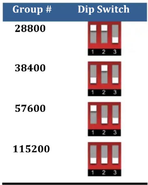
Figure 4.3 - DIP-Switch Settings
MULTICAST GROUP: The 6 position dip switch is used to assign the group number (channel number) video is cast on the network. Similar to the baud Dip-switch, it is set from left (least significant bit) to right (most significant bit). Again, if you use the Windows™ GUI tool you will have a graphical image of the dip switch making it easy to set.
RESET: This button has two uses. Press it momentarily to cause a reboot (same as power cycle). Press and hold for 10 seconds to restore factory defaults.
NOTE You have the option to completely ignore the dip-switches!
As mentioned earlier both Baud Rate and MultiCast Group/Channel number can be set in both WebGUI of each unit or the Windows TM tool. So why have dip switches at all?
By default when units are powered up the devices revert to the dip-switch positions. This may be useful in certain situations. For example: if there is a power interruption or outage in the building you can make sure the system comes up in a known state every time (as determined by the dip-switches). Having dip-switches also speeds up installation of a simple, static system without worrying about IP configuration. Just set the dip-switches to pair Receivers & Senders and you are done.
There is a setting in the WebGUI of each device to ignore the dip-switches on power up and recall the previous setting from memory.
When this option is selected, the dip-switches perform no function whatsoever!
4.3 Receiver's Front and Rear Panels
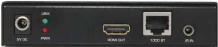
Figure 4.4 - Receiver's Front Panel

Figure 4.5. Receiver's Rear Panel
The functions of the connectors on the Receiver are similar to those of the Sender described in the previous section.
5.0 OSD Menu
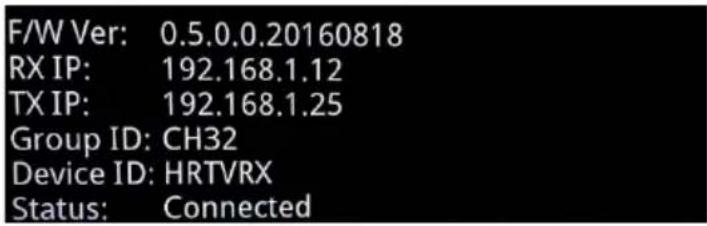
Figure 5.1 - OSD
Once the installation is completed, the following On Screen Display (OSD) is displayed on the screen. The OSD behavior can be controlled using Hall Research's Dynamic Virtual Matrix Tool™ Windows Software or Telnet command. The user can conveniently select Auto, ON, OFF options. Auto allows the OSD to be displayed for 10 seconds, while the user can select the ON and OFF feature to enable or disable the OSD.
F/W Ver: The firmware version.
RX IP: This receiver's IP address.
TX IP: The connected transmitter's IP address. Note that the transmitter and the receiver must be in the same group else 0.0.0.0 will be displayed.
GROUP ID: This receiver's group number.
DEVICE ID: This receiver's device name (user assignable).
STATUS: Shows the link status. If no transmitter is found in the receiver's group "Waiting for connection..." will be displayed.
If the TX and RX are in the same group, but no HDMI source connected to the TX, then the message "Stream Not Found!" will be displayed.

Figure 5.3 - OSD - No Video Source
The On Screen Display (OSD) will be based on the selection (Auto, ON, OFF) in the software GUI or Telnet command.

Figure 5.4 - Selection of OSD behavior in DVM Software Tool
6.0 Group ID Setup for TX and RX
The Group ID for HHD264 can be setup using 4 methods – DIP-switch, WEBGUI, Windows™ GUI and Telnet command.


Figure 6.1 - Group Setting in WebGUI and DVM Windows™ Software Tool
6.1. Use DIP Switch On Power Up - Group ID
The “Use DIP Switch on Power Up” feature allows the user to have a control on the Group ID settings if there is a power interruption. By enabling this option, the HHD264 uses the DIP switch position after power up. When not selected, the unit recalls the last setting prior to shutdown.
7.0 RS232
RS232 communication in HHD264 is bi-directional. The controller or the controlled device can be either at the Sender's or the Receiver's end. The baud rate for the TX and RX can be configured using the DIP switch, WEBGUI and the Windows GUI. The RS-232 pin-outs are shown below.
| DB9-Female on HHD264-S | |
| Pin | Function |
| 2 | TX (output) |
| 3 | RX (input) |
| 5 | Ground |
| DB9-Male on HHD264-R | |
| Pin | Function |
| 2 | RX (input) |
| 3 | TX (output) |
| 5 | Ground |
8.0 WebGUI
As shipped from the factory (or after restoring factory defaults), the HHD264 IP address is set for DHCP and the IP address will be assigned by the router.
8.1 Finding the HHD264 IP addresses on the LAN
- The free Hall Research Windows™ Dynamic Virtual Matrix Manager Tool can locate the HHD264s IP addresses on the network.
○ Selecting (double click) any device displayed; opens a window where certain fields are modifiable. - It lists all the devices found with their User defined names, IP addresses and Multicast Group channels. Columns are sortable (for example you can sort by device name). Senders are listed on the left and Receivers on the right.
- Click the "Update" button after making any changes.
- Click the "Reboot" button to reboot the device.

Figure 8.1 - PC GUI - SCAN TAB
After finding the IP address of the device, open the browser and enter the IP on the address bar. If the page login feature is enabled, then the following window appears..

Figure 8.2 - WEBGUI Login Page
Enter the login credentials. By default, the credentials are as follows
Username: admin
Password: admin
8.2 WebGUI Explained
Below is an image of Sender's WebGUI. The Receiver's WebGUI is very similar to the Sender's but is missing several fields that are only in the Sender's GUI.

Figure 8.3 - Sender - WEBGUI Information Page
Device Info
- Model Name: Shows the model number of the transmitter device.
■ Device ID: Enter the name of the device up to 30 alphanumeric characters. - Group ID: Select the channel number for the transmitter. The TX and RX have to be in the same Group ID to pass video.
- Use DIP Switch On Power Up: Select this checkbox if you want to use the group ID of the DIP switch setting on the panel on power up.
HHD264
■ MAC Address: Shows the unique MAC address of the device.
- FW Version: Shows the Firmware version of the transmitter.
■ EN Version: Shows the Encoder version of the transmitter.
Click "Update Device Info" to confirm the settings.
Password
- Enable Login: Select this checkbox if you need a page login for the WebGUI. You need to enter the old password (default is admin) followed by the new password to activate the page login feature
- Old Password: Enter the previously saved password. As shipped from factory, this is “admin”.
- New Password: Enter the new password; can be up to six characters long. Accepts alphanumeric and special characters.
■ Confirm Password: Re-type the password to confirm the settings
RS232 Baud Rate
- Baud Rate: Select the desired baud rate from the drop-down list box. Please note that the baud rate of the control device, TX and RX must be the same for communication.
■ Device ID: Enter the name of the device up to 30 alphanumeric characters. - Use DIP Switch On Power Up: Select this checkbox if you want to use the DIP switch setting for the baud rate on the panel while powering up. If there is a power interruption and if you need to use the DIP switch setting as your desired baud rate, then check this box. If this is not checked, the last saved baud rate takes into effect.
- Click "Update RS232" to confirm the settings.
Upgrade This section is for firmware upgrade, reboot and factory default.
- FW Filename: Select the Firmware file (.pkg) of the transmitter for firmware upgrade.
■ EN Filename: Shows the Encoder Version of the transmitter. - Update Firmware: After selecting the firmware file (.pkg), click “Update Firmware” to update it.
- Update Encoder: After selecting the encoder file (.bin), click "Update Encoder" to update it.
- Reboot: Click this to restart the device while keeping the settings intact.
- Factory Default: Factory resets the unit. All the saved settings will be erased and restored to factory default.
Network Settings
- Enable DHCP: Use DHCP to automatically assign IP address to the TX and RX in the network. A DHCP router has to be connected to the network.
■ Static IP: Enter the IP address manually if DHCP is disabled.
- SubNetmask: Enter the subnet mask as assigned by your network administrator.
- Gateway: Enter gateway IP address for the device and the PC.
- Click "Update Settings" to confirm the settings.
NOTE
Contact your network administrator if you are unsure of how to configure the existing network.
Scaler Settings These settings are only in the Sender (See Section 10)
- Scale Full HD to: In order to decrease the network traffic, if the input video is FHD 1080p source, then select this to downscale it to High Definition (HD) and Standard Definition (SD).
- Scale HD to: This downscales the HD input video to Standard Definition (SD).
Encoder Settings These settings are only in the Sender (See Section 10)
- Full HD Bit Rate: The bit rates range from 10000-18000 Kbps for FHD (1080p) input video.
- HD Bit Rate: Select from the range between 8000 and 16000 Kbps for HD(1080i & 720p) input video.
- SD Bit Rate: Select from the range 2000-8000 Kbps for SD (576p, 576i, 480p & 480i) input video.
Video Information These settings are only available in the Sender WebGUI
- Input Resolution: Shows the HDMI source's resolution to the HDMI input of the transmitter.
- Input Frame Rate: Shows the refresh rate of the source.
9.0 Encoder and Scaler Settings
The HHD264 has internal scaling capabilities. The user can control the bit rate and the scaling feature depending on the network bandwidth. The user can change the settings in three ways – WEBGUI, Telnet and PC GUI. Please consider the following if you decide to change settings from default:
- The input of the sender is the source video fed into the sender.
- The output of the sender is the network stream.
- Reducing the bit rate will decrease the occupied bandwidth on the network.
- By default as shipped, these settings are optimized for the best image possible without undue burden on the network.
9.1 Encoder and Scaler Settings - WebGUI and PC GUI
If you are using a source with 1080p resolution, then use “Scale Full HD to :” option to either transmit the video at the same resolution on the network, or to first downscale the video from Full HD to HD (or SD) and then transmit the lower resolution image on the network. By doing so you will force the unit to use the bit rate for HD instead of Full-HD which is typically much lower bit rate. Understand that you will be lowering the resolution from 1080p/60 to 720p/60. But if the video has a lot of motion and action, the compression will be able to keep up better at 720p and still reproduce a clear image in the presence of all large areas of moving objects on the screen.
However, if you have a Full HD (1080p) source video where the amount of motion on the screen image is limited (such as a slide show), you can skip scaling it down and just reduce the bit rate for Full HD. That way you are not sacrificing any resolution of the original image.
If you are using a 720p source resolution, the use “Scale HD to:” option to downscale the video to Standard Definition (SD) to transmit in the network.
Click "Update Scaler" to confirm the settings. See Figure 9.1.


Figure 9.1 - Sender Encoder and Scaler Settings in WebGUI and PC GUI
Once the Scaling Settings are confirmed, select the Full HD, HD and SD bit rate in the Encoder Settings section and click "Update Encoder".
| Resolution | Bit Rate – Range (Kbps) |
| 1080p (FHD) | 10000-18000 |
| 720p, 1080i (HD) | 8000-16000 |
| 480p, 480i, 576p, 576i (SD) | 2000-8000 |
10.0 Telnet Commands - Transmitter and Receiver
HHD264 offers excellent control features where the user can obtain information from each unit such as Group ID, Name, IP configuration, etc. from a remote location.
- Telnet operation via specified port 9999 can be achieved by connecting the sender and receiver in a dedicated telnet session.
- Open the telnet session using a terminal software program.
- Type "Telnet 192.168.x.x 9999" to ping the sender or receiver.
- Commands are case sensitive.
- Use lowercase characters.
- Invalid command is responded with "Unknown Input Command".
- "list
" displays all the commands.
| All Commands are Terminated by(or Hex 0D 0A) | Response | Function |
| set_group_id nwhere n=0-1023 | OK - SuccessError - Fail | Set Group ID |
| get_group_id | nwhere ‘n” returns the group ID | Query the current group ID status |
| set_dhcp | OK - SuccessError - Fail | Set the DHCP mode |
| get_dhcp | On - DHCPOff - No DHCP | Query the DHCP status |
| Set_uart_baudrate nWhere n = 2400, 4800, 9600, 19200, 28800, 28400, 57600, 115200 | OK - SuccessError - Fail | Set the baud rate for the RS232 on the unit |
| get_uart_baudrate | nwhere n = baud rate | Query the current baud rate setting in the unit |
| set_static_ip ip [ip(n.n.n.n)] netmask [ip(n.n.n.n)] gateway [ip(n.n.n.n)]Where:ip [ip(n.n.n.n)] =IP xxx. xxx. xxx. xxxnetmask[ip(n.n.n.n)]=netmask 255.255.xxx.xxxgateway [ip(n.n.n.n)] = gateway xxx. xxx. xxx. xxx | OK - SuccessError - Fail | Set the static IP configuration for the unit |
| get_static_ip | Ip: 192.168.1.xxNetmask: 255.255.0.0Gateway: 192.168.1.1 | Returns the current static IP configuration |
| get_mac_address | XX:XX:XX:XX:XX:XX | Query the MAC address of the unit |
| get_lan_status | Link_Up/Link_Down | Query LAN Status whether device is UP and connected to the switch |
| get_ip_config | Ip: XXX.XXX.XXX.XXXNetmask: XXX.XXX.XXX.XXXGateway: XXX.XXX.XXX.XXX | Shows IP Configuration settings |
HHD264
| All Commands are Terminated by(or Hex 0D 0A) | Response | Function |
| get_hdcp_status | OnOffWhere On - Input Video with HDCPOff- Input Video without HDCP | Query the HDCP status of the video input |
| get_video_lock | LockUnlockWhere Lock - Stable Input SignalUnlock - No input video or unstable | Query the video stability status |
| set_session_key [0xhhhh(1~32)] | OK-SuccessError-FailWhere[0xhhhhh(1~32)]=0x000000~0xffff | Set session key for encryption |
| set_screen off|on (Receiver ONLY)Where off=blank on=unblank | OK - SuccessError - Fail | Set video blank/unblank the screen |
| get_screen (Receiver ONLY) | onoff | Query the device output status |
| set_group_powerup [string(off|on)]off= Ignore DIP-Sw on power upon= Use DIP-Sw on power up (default) | OK - SuccessError - Fail | Selects “Use DIP switch on power up” for grouping |
| get_group_powerup | onoff | Query the status of the” Use DIP on power up” for group setting |
| set_rs232_powerup [string(off|on)]off= Don’t use DIP switch on power upon= Use DIP sw on power up (default) | OK - SuccessError - Fail | Selects “Use DIP switch on power up” for baud rate |
| get_rs232_powerup | onoff | Query the status of the “Use DIP on power up” for baud |
| set_page_login [string(off|on)]where off = Disable login for the webpage session (default)on= Enable login for theweb page. | OK - SuccessError - Fail | Set the login page for the WebGUI |
| get_page_login | onoff | Query the webpage” login enable” status |
| set_video_bitrate (Sender ONLY)[string(fhd|hd|sd)][n(2000~18000)]Where:string(fhd|hd|sd)][n(100~25000)] can be fhd, hd, sd and 12000For example:set_video_bitrate fhd 12000 | OK - SuccessError - Fail | Set the max bit rate for the TX to sender over the network. Limits apply see Section 10 |
| get_video_bitrate [string(fhd|hd|sd)] (Sender ONLY) | xxxx | Query the bit rate for the TX |
| set_downscale_mode string(fhd|hd|sd)]to string(fhd|hd|sd)] | OK - SuccessError - Fail | Scale down the input video to lower resolution |
| get_downscale_mode string(fhd|hd|sd)] (Sender ONLY) | string(fhd|hd|sd)] | Get the downscale mode status |
| set_video_out_modestring(both_on|loopthrough|network|both_off)] (Sender ONLY) | OK - SuccessError - Fail | Enable the HDMI output and network output |
| get_video_out_mode (Sender ONLY) | string(both_on|loopthrough|network|both_off)] | Query the Loop and network output status |
| set_osd [string(auto|on|off)]Auto= OSD will turn off when there is an input signal detected.On or Off - OSD Stays on or off forever | OK - SuccessError - Fail | Set OSD mode of the system |
| get_osd | AutoOnOff | Query the OSD mode status |
| set_device_name [string(1~30)]Where string can be 30 characters long | OK - SuccessError - Fail | Set the device name |
| get_device_name | [string(1~30)] | Query the device name |
| get_fw_version | Tx/Rx Firmware : x.x.x.x.xxxxxxxxxReturns the firwmare version | Query the firmware version |
| factory_reset | Processing factory reset!System will reboot after few sec! | Factory reset the device |
| Reboot | System will reboot after few sec! | To reboot the unit |
| get_company_id | xxx | Query the company ID |
| set_streaming_mode[string(unicast|multicast)] | OK - SuccessError - Fail | Set the streaming mode of the device |
| get_streaming_mode[string(unicast|multicast)] | [string(unicast|multicast)]where unicast means one-one configuration and multicast means one to many and many-to-many configuration | Query streaming mode status |
| Exit | Exits the telnet session |
11.0 EDID
The HHD264 offers EDID management meaning that the user can write a custom EDID file into the device using the HDMI input of the transmitter, HHD264-S. Hall Research's EMX-HD-AUD audio extractor and EDID manager works perfect to achieve this purpose.
NOTE
Factory resetting the HHD264 will restore back the default Hall Research EDID to the device. The user must confirm the action and take all necessary precautions to prevent loss of data. Hall Research is not responsible for any damage that may occur from the user attempting to modify the EDID..
12.0 Power over Ethernet (PoE)
The HHD264 Senders and Receivers with -PD suffix can utilize Power Over Ethernet (PoE) eliminating the need to connect a power supplies to the unit. The device gets its power from the PSE (Power Sourcing Equipment) port in the Gigabit PoE switch. The -PD units also include power supply in case needed.
13.0 Firmware Upgrade
The firmware upgrade on HHD264 can be completed using the WEBGUI. Contact Hall Research for more details.
14.0 Recalling Factory Defaults
Factory defaults resets are parameters (including network settings) back to default. There are 4 ways to recall factory defaults:
- Press the RESET button on the unit for 10 seconds.
- Use telnet command "factory reset
" - Factory Default is available on the Software GUI. Wait for 10 seconds for the device to reboot and activate.
- WebGUI also offers factory resetting the device.
15.0 Troubleshooting
There are no field serviceable parts or circuits in the device. If you think the device is malfunctioning (or you have no picture output), please try to use the following methods to obtain a picture first.
15.1 Getting a Picture on the Output
- If there is no picture on the display, you can “quick press” the RESET button on the unit’s panel to reboot the device while keeping the current IP settings intact.
- If you still have issues, try factory resetting the unit by holding the RESET button on the panel for 10 seconds. All the settings will be erased and set to factory default.
- In a one to many and many-to-many configuration, if there are displays with different native resolution and there is no picture on some displays, then it is highly recommended to use the “Scaler Settings” in the TX’s WebGUI.
For example, if there is a 1080p HDMI source connected to the transmitter and a 720p monitor is present among many1080p monitors connected to other receivers, then select scale “Full HD to HD” in Encoder Settings in the web page so that all the monitors get a resolution of HD 720p video, thereby, resulting in an image. Once you have an image, you can check up the OSD menu if necessary. If you still have trouble in getting the picture on the output, make sure all the cables are connected to the HHD264 and the gigabit switch/router.
15.2 Contacting Hall Research
If you determine that your HHD264 is malfunctioning, do not attempt to repair the unit instead, contact Hall Research Technical Support at 714-641-6607. To return the unit to Hall Research you must first get a Return Authorization (RMA) number. Package the unit carefully, if returning. We recommend that you use the original container.
16.0 Specifications
| ProtocolInput Resolution | H.264 encodingVGA or 480p thru Full HD 1080p@60 |
| TransmitterInput PortsOutput Ports | 1 x HDMI1 x RJ45, 1 x HDMI, 1 x IR |
| ReceiverInput PortsOutput Ports | 1 x RJ45, 1 x IR1 x HDMI |
| RS232 Port | TX 1x DB9 FemaleRX 1x DB9 Male |
| Baud Rate | Bidirectional, pass thru 2400 – 115200 bps |
| Audio | HDMI Stereo 2-channel |
| IR Frequency | 38 -56 KHZ pass-thru modulated |
| Group ID | Up to 64 groups |
| Switch/Router | Gigabit IGMP and DHCP support |
| Operating Temp | +32 to +113°F (0 to +45 °C)20%~90%, non-condensing |
| Power consumption | Max. 3 W |
| Mounting Option | Mounting Brackets (included) |
| Dimensions | 4.72"(120.2mm) W x 3.09"(78.6mm) D x 1.14"(29 mm) H |
| Net Weight | TX: 0.28KG RX:0.28KG |
HR HALL RESEARCH
© Copyright 2017. Hall Research, Inc. All rights reserved.
1163 Warner Ave., Tustin, CA 92780 Ph: (714)641-6607
- HHD264
- HDMI DISTRIBUTION AND SWITCHING OVER LAN WITH RS-232 & IR EXTENSION DYNAMIC VIRTUAL MATRIX™
- TABLE OF CONTENTS
- 1.0 INTRODUCTION......4
- 4.0 CONFIGURATION & OPERATION....10
- 6.0 GROUP ID SETUP FOR TX AND RX....13
- 9.0 ENCODER AND SCALER SETTINGS....17
- 10.0 TELNET COMMANDS - TRANSMITTER AND RECEIVER......19
- TRADEMARKS USED IN THIS MANUAL
- FCC RADIO FREQUENCY INTERFERENCE STATEMENT
- 1.0 INTRODUCTION
- 1.1 GENERAL
- 1.2 FEATURES
- 2.0 PACKAGE CONTENTS
- 3.0 INSTALLATION
- 3.1 CONFIGURATION
- POINT-TO-POINT
- POINT-TO-MANY (SPLITTER) AND MANY-TO-MANY (MATRIX)
- NOTE
- HARDWARE SETUP
- 3.1.2 SETTING THE IP ADDRESS
- DHCP - DEFAULT
- SETTING STATIC IP
- 4.0 CONFIGURATION & OPERATION
- 4.1 SENDER'S FRONT PANEL
- 4.2 SENDER'S REAR PANEL
- NOTE YOU HAVE THE OPTION TO COMPLETELY IGNORE THE DIP-SWITCHES
- 4.3 RECEIVER'S FRONT AND REAR PANELS
- 5.0 OSD MENU
- 6.0 GROUP ID SETUP FOR TX AND RX
- USE DIP SWITCH ON POWER UP - GROUP ID
- 7.0 RS232
- 8.0 WEBGUI
- 8.1 FINDING THE HHD264 IP ADDRESSES ON THE LAN
- 8.2 WEBGUI EXPLAINED
- DEVICE INFO
- PASSWORD
- RS232 BAUD RATE
- UPGRADE THIS SECTION IS FOR FIRMWARE UPGRADE, REBOOT AND FACTORY DEFAULT
- NETWORK SETTINGS
- SCALER SETTINGS THESE SETTINGS ARE ONLY IN THE SENDER (SEE SECTION 10)
- ENCODER SETTINGS THESE SETTINGS ARE ONLY IN THE SENDER (SEE SECTION 10)
- VIDEO INFORMATION THESE SETTINGS ARE ONLY AVAILABLE IN THE SENDER WEBGUI
- 9.0 ENCODER AND SCALER SETTINGS
- 9.1 ENCODER AND SCALER SETTINGS - WEBGUI AND PC GUI
- 10.0 TELNET COMMANDS - TRANSMITTER AND RECEIVER
- 11.0 EDID
- 12.0 POWER OVER ETHERNET (POE)
- 13.0 FIRMWARE UPGRADE
- 14.0 RECALLING FACTORY DEFAULTS
- 15.0 TROUBLESHOOTING
- 15.1 GETTING A PICTURE ON THE OUTPUT
- 15.2 CONTACTING HALL RESEARCH
- 16.0 SPECIFICATIONS
- HR HALL RESEARCH
Brand : Hall Research
Model : HHD264-R-PD
Category : AV Cable