
PowerCage FOX Rx HDMI MM - WiFi Repeater Extron - Free user manual and instructions
Find the device manual for free PowerCage FOX Rx HDMI MM Extron in PDF.


| Product Type | WiFi Repeater / HDMI Receiver |
| Dimensions (H x W x D) | 1.7" x 17.0" x 10.0" (1U rackmount) |
| Weight | 3.5 lbs (1.6 kg) |
| Power Supply | 100-240V AC, 50/60 Hz, internal |
| Input Connectors | 1x HDMI, 1x RJ-45 (FOX link) |
| Output Connectors | 1x HDMI, 1x RJ-45 (loop-through) |
| Video Resolution | Up to 1920x1200 or 1080p |
| Audio Support | Embedded audio pass-through |
| Maximum Cable Distance | Up to 300 ft (90m) over CATx |
| Control Interfaces | RS-232, IR, Ethernet |
| Mounting | 1U rackmount with included brackets |
| Operating Temperature | 0 to 50°C |
| Cooling | Fan-cooled, quiet operation |
| LED Indicators | Power, Link, Signal |
| RoHS Compliant | Yes |
| Warranty | 3 years parts and labor |
| Cleaning | Use dry cloth; avoid liquids |
| Safety | Follow installation instructions; avoid overheating |
| Repairability | Refer to qualified service personnel; no user-serviceable parts |
Frequently Asked Questions - PowerCage FOX Rx HDMI MM Extron
User questions about PowerCage FOX Rx HDMI MM Extron
0 question about this device. Answer the ones you know or ask your own.
Ask a new question about this device
Download the instructions for your WiFi Repeater in PDF format for free! Find your manual PowerCage FOX Rx HDMI MM - Extron and take your electronic device back in hand. On this page are published all the documents necessary for the use of your device. PowerCage FOX Rx HDMI MM by Extron.
USER MANUAL PowerCage FOX Rx HDMI MM Extron
High Resolution Fiber Optic Transmitters and Receivers

Safety Instructions • English
This symbol is intended to alert the user of important operating and maintenance (servicing) instructions in the literature provided with the equipment.
This symbol is intended to alert the user of the presence of uninsulated dangerous voltage within the product's enclosure that may present a risk of electric shock.
Caution
Read Instructions • Read and understand all safety and operating instructions before using the equipment.
Retain Instructions • The safety instructions should be kept for future reference.
Follow Warnings • Follow all warnings and instructions marked on the equipment or in the user information.
Avoid Attachments • Do not use tools or attachments that are not recommended by the equipment manufacturer because they may be hazardous.
Power sources • This equipment should be operated only from the power source indicated on the product. This equipment is intended to be used with a main power system with a grounded (neutral) conductor. The third (grounding) pin is a safety feature, do not attempt to bypass or disable it.
Power disconnection • To remove power from the equipment safely, remove all power cords from the rear of the equipment, or the desktop power module (if detachable), or from the power source receptacle (wall plug).
Power cord protection • Power cords should be routed so that they are not likely to be stepped on or pinched by items placed upon or against them.
Servicing • Refer all servicing to qualified service personnel. There are no user-serviceable parts inside. To prevent the risk of shock, do not attempt to service this equipment yourself because opening or removing covers may expose you to dangerous voltage or other hazards.
Slots and openings • If the equipment has slots or holes in the enclosure, these are provided to prevent overheating of sensitive components inside. These openings must never be blocked by other objects.
Lithium battery • There is a danger of explosion if battery is incorrectly replaced. Replace it only with the same or equivalent type recommended by the manufacturer. Dispose of used batteries according to the manufacturer's instructions.
Avertissement
This equipment has been tested and found to comply with the limits for a Class A digital device, pursuant to part 15 of the FCC Rules. Operation is subject to the following two conditions: This device may not cause harmful interference.
- This device must accept any interference received, including interference that may cause undesired operation.
The Class A limits are designed to provide reasonable protection against harmful interference when the equipment is operated in a commercial environment. This equipment generates, uses, and can radiate radio frequency energy and, if not installed and used in accordance with the instruction manual, may cause harmful interference to radio communications. Operation of this equipment in a residential area is likely to cause harmful interference, in which case the user will be required to correct the interference at his own expense.
NOTE: This unit was tested with shielded cables on the peripheral devices. Shielded cables must be used with the unit to ensure compliance with FCC emissions limits. For more information on safety guidelines, regulatory compliances, EMI/EMF compliance, accessibility, and related topics, click here.
Conventions Used in this Guide
Notifications
DANGER: A danger indicates a situation that will result in death or severe injury.
WARNING: A warning indicates a situation that has the potential to result in death or severe injury.
CAUTION: A caution indicates a situation that may result in minor injury.
ATTENTION: Attention indicates a situation that may damage or destroy the product or associated equipment.
NOTE: A note draws attention to important information.
TIP: A tip provides a suggestion to make working with the application easier.
Software Commands
Commands are written in the fonts shown here:
^AR Merge Scene,,Op1 scene 1,1 ^B51 ^W^C
[01] R000400300004000080000600 [02] 35 [17] [03]
Esc X1 * X17 * X20 * X23 * X21 CE
NOTE: For commands and examples of computer or device responses mentioned in this guide, the character "∅" is used for the number zero and "0" represents the capital letter "o."
Computer responses and directory paths that do not have variables are written in the font shown here:
Reply from 208.132.180.48: bytes=32 times=2ms TTL=32
C:\Program Files\Extron
Variables are written in slanted form as shown here:
ping xxx.xxx.xxx.xxx -t
SOH R Data STX Command ETB ETX
Selectable items, such as menu names, menu options, buttons, tabs, and field names are written in the font shown here:
From the File menu, select New.
Click the OK button.
Copyright
© 2012 Extron Electronics. All rights reserved.
Trademarks
All trademarks mentioned in this guide are the properties of their respective owners.
Contents
Introduction ...... 1
About this Guide 1
About the PowerCage FOX HDMI Transmitters and Receivers 2
Transmitter....2
Receiver 2
Transmitter and Receiver 3
System Compatibility 3
Cable Transmission Modes 3
Features....4
Installation and Operation....5
Mounting the Units.... 5
Rear Panel Connections, Controls, and Indications....5
Making Connections....10
Transmitter Side Panel Controls 13
PowerCage Front Panel Port, Control, and Indicators....14
Operation 16
Remote Control......17
Serial Ports....17
Simple Instruction Set Control....18 Host-to-unit Instructions....18
Unit-initiated Messages....18
Error Responses.... 18
Using the Command and Response Tables 19
FOX Extenders Control Program....26
Installing the Software 26
Starting the Program....26
Firmware Upgrade 33
Reference Information ....37
Specifications....37
Part Numbers....40
PowerCage FOX Part Numbers......40
Included Parts 40
Cables 40
Adapters....41
Installing a Board in the Enclosure 42
Introduction
WARNING: The PowerCage™ Tx/Rx HDMI units output continuous invisible light, which may be harmful to the eyes; use with caution.
- Do not look into the rear panel fiber optic cable connectors or into the fiber optic cables themselves.
-
Plug the attached dust caps into the optical transceivers when the fiber cable is unplugged.
-
About this Guide
- About the PowerCage FOX HDMI Transmitters and Receivers
- Features
About this Guide
This guide contains information about the Extrone® PowerCage FOX Tx HDMI transmitter and PowerCage FOX Rx HDMI receiver. These units are modular board-designed fiber optic transmitters and receivers for the PowerCage Modular Power Enclosures.

flowchart
graph TD
    A["Blu-Ray Player"] -->|HDMI| B["Extron PowerCage FOX Tx HDMI"]
    B --> C["Extron PowerCage 1600"]
    C --> D["Extron FOXBOX Rx HDMI Fiber Optic Receiver"]
    D --> E["Extron XPA 1002 Power Amplifier"]
    E --> F["Extron SI 28 Surface-mount Speakers"]
    D --> G["Flat Panel Display"]
    style A fill:#f9f,stroke:#333
    style B fill:#ccf,stroke:#333
    style C fill:#cfc,stroke:#333
    style D fill:#fcc,stroke:#333
    style E fill:#cff,stroke:#333
    style F fill:#ffc,stroke:#333
Figure 1. Typical PowerCage FOX Tx/Rx HDMI Application
This guide includes instructions for an experienced installer to install, configure, and operate the equipment.
About the PowerCage FOX HDMI Transmitters and Receivers
The PowerCage FOX HDMI Fiber Optic Extender is an ultra-high performance fiber optic transmitter and receiver set for long haul transmission of HDCP-compliant HDMI video, audio, and RS-232 control signals over fiber optic cabling. The transmitter and receiver can extend HDMI signals up to 30 km (18 miles).
NOTE: For HDCP compliance:
- A PowerCage FOX HDMI or FOXBOX HDMI transmitter must be paired with a PowerCage FOX HDMI or FOXBOX HDMI receiver.
- You must connect both fiber optic cables between the transmitter and receiver.
• A signal cannot be daisy-chained and retain HDCP compliance.
• The bidirectional Consumer Electronics Control (CEC) is not supported.
Transmitter
The PowerCage FOX Tx HDMI transmitter accepts HDMI video or DVI-D video (with an applicable adapter), at resolutions up to 1920 x 1200 at 60 Hz. The video input can also include embedded audio.
The transmitter can also accept an analog audio input on a 3.5 mm mini jack. An internal DIP switch selects either the embedded audio or the separate analog audio for the unit to transmit to the receiver.
The transmitter accepts a one-way (transmitter-to-receiver) RS-232 serial communication signal input (projector control, for example). The transmitter can receive an optional return (receiver-to-transmitter) stream of serial RS-232 communications (projector responses, for example).
The transmitter converts the HDMI video, the selected audio, and the RS-232 serial communication into a proprietary data stream and outputs it as an optical signal on a single LC connector to a compatible fiber optic receiver. It also can receive a proprietary optical signal from the receiver consisting of the RS-232 return from a controlled device.
Receiver
The PowerCage FOX Rx HDMI receiver accepts a proprietary optical signal on a single LC connector from a compatible fiber optic transmitter or daisy-chained receiver and outputs a single link of HDMI video, digital audio (embedded in the HDMI output), analog audio, and RS-232 serial commands.
If the receiver is appropriately configured and has a second fiber optic cable installed, it also can either:
- Receive an RS-232 return from a controlled device and send it to the transmitter via a proprietary optical signal.
• Output a daisy-chained signal to another receiver.
If either RS-232 return or daisy-chained communications are implemented, the receiver outputs a proprietary signal on the second fiber optic cable carrying the signal.
For video resolutions up to 1600 x 1200, 1080p, or 1920 x 1200, the video output of the receiver is a perfect, pixel-for-pixel recreation of the video signal input to the transmitter.
With the appropriate adapter, the single link of HDMI video output by the receiver can be converted to DVI-D video.
The receiver has built-in alternating pixels, color bars, and grayscale test patterns to assist in setting up the display equipment.
Transmitter and receiver
The transmitter and receiver have many controls, including image and audio adjustments, and available under RS-232 Simple Instruction Set (SISTM) control. Both units have image, audio, and fiber light status and lost-light alarm indicators.
System Compatibility
The PowerCage FOX Tx HDMI transmitter operates in either of two modes, selected under RS-232 control, for compatibility with other, non-HDMI, units:
- Plus — Supports resolutions up to 1920 x 1200 @ 60Hz. The fiber optic output of the transmitter can be received only by one of four receivers: a PowerCage HDMI Rx, a PowerCage FOX DVI Plus Rx, a FOXBOX HDMI Rx, or a FOXBOX DVI Plus Rx.
- Non-plus — Supports resolutions up to 1600 x 1200 @ 60 Hz or 1080p. The fiber optic output of the transmitter can be received by any PowerCage FOX, FOXBOX, and FOX 500 VGA, and DVI unit, including the Plus and non-Plus units.
The FOXBOX Rx HDMI receiver operates interchangeably with all PowerCage FOX, FOXBOX, and FOX 500 VGA and DVI units, including Plus and non-Plus units.
NOTE: Although the receiver can operate with non-HDMI transmitters, the video output is not HDCP-compliant.
- The transmitter and receiver are not compatible with the PowerCage FOX AV, FOX AV, PowerCage FOX 3G HD-SDI, FOX 3G HD-SDI, and FOX 3G DVC models.
Cable Transmission Modes
The transmitter and receiver are further categorized by the type of fiber optic cable, multimode or singlemode, which defines the effective range of transmission:
- Multimode — Long distance, up to 2 km (6,560 feet) (depending on the fiber cable)
• PowerCage FOX Tx HDMI MM
• PowerCage FOX Rx HDMI MM
- Singlemode — Very long distance, up to 30 km (18.75 miles)
• PowerCage FOX Tx HDMI SM
• PowerCage FOX Rx HDMI SM
NOTE: The multimode and singlemode units are physically and functionally identical, with the exception of the effective range of transmission. In this guide, any reference applies to either transmission mode unless otherwise specified.
Features
Ultra high performance — Offers pixel-for-pixel HDMI or DVI-D (with an adapter) video transmission, up to 1920 x 1200 at 60 Hz (in plus mode) or 1600 x 1200 at 60 Hz (in non-plus mode).
Video input — The transmitter accepts a single link of HDMI or DVI-D video.
EDID emulation mode (Display Data Channel [DDC]) — The PowerCage FOX Tx HDMI transmitter provides a selector switch for specifying the rate of the incoming digital video signal. EDID emulation mode allows proper operation
Video output — The receiver outputs a single link of HDMI video.
Extron fiber optic product compatibility — Enables ultra-long distance HDMI-to-analog RGB and analog RGB-to-HDMI conversion without the need for extra signal conversion devices.
Compatibility with FOX 500 DA6 distribution amplifier and FOX Matrix Switchers
Analog audio input — The transmitter accepts an unbalanced stereo audio input on a 3.5 mm mini jack.
Analog audio input gain/attenuation — The input audio level can be adjusted within a range of -18 dB (attenuation) to +10 dB (gain) via the RS-232 link.
Analog audio output — The receiver outputs balanced or unbalanced stereo audio on a 3.5 mm, 5-pole captive screw terminal.
Links monitoring — The panels of the transmitters and receivers have indicators for monitoring both fiber optic links.
Loss-of-light alarms — The rear panels of the transmitters and receivers have discrete outputs that indicate if either of the fiber optic links has suffered a loss of the light signal.
FOX Extenders Control Program — For RS-232 remote control from a PC running Windows ^® , the Extron FOX Extenders control software provides a graphical interface and drag-and-drop, point-and-click operation.
Simple Instruction Set (SIS) — The transmitter and receiver use the SIS for easy remote control operation.
Audio level — The audio output can be set to either the consumer level (-10 dBV) or professional level (+4 dBu) under RS-232 control.
Upgradable firmware — The firmware that controls the operation of each unit can be upgraded in the field via the Configuration port on the PowerCage enclosure without taking the unit out of service. Firmware upgrades are available for download on the Extron website, www.extron.com, and they can be installed using the FOX Extenders Control Program.
Memory presets — 30 memory presets let you store input size and position settings relative to a specific input resolution. You can then recall those settings, when needed, using the SIS or the control software.
PowerCage mounting — All PowerCage FOX Tx and Rx units are mountable in any Extron PowerCage enclosure.
LockIt™ HDMI Cable Lacing Bracket — Each transmitter and receiver includes a LockIt bracket to secure the HDMI cable to the unit.
Installation and Operation
This section describes the installation and operation of the PowerCage FOX HDMI, including:
- Mounting the Units
• Rear Panel Connections, Controls, and Indications
• Transmitter Side Panel Controls
• PowerCage Front Panel Port, Control, and Indicators - Operation
Mounting the Units
The PowerCage FOX transmitter or receiver must be installed in an Extron PowerCage enclosure (see "Installing a Board in the Enclosure" on page 42.)
Rear Panel Connections, Controls, and Indications

Figure 2. PowerCage FOX Tx Transmitter Connectors, Controls, and Indications
① HDMI Input connector — Connect a single link of HMI video to this connector. See "HDMI connectors" on page 10 for pin assignments and to use the LockIt HDMI Cable Lacing Bracket to secure the connector to the transmitter.
② Audio Input connector — Connect an unbalanced stereo or mono audio input to this connector.
The input audio level can be set via RS-232 control (see "Audio Adjustment area" in the "Remote Control" section on page 29.


③ RS-232 Over Fiber port — If you want the transmitter and receiver system to pass serial command signals between the transmitter and receiver, for example for serial control of a projector, connect the host device to the transmitter and the slave device to the receiver via the leftmost three poles on the left (Tx, Rx, and 12 ) of the 5-pole captive screw connectors on both un "RS-232 connectors" on page 11 to wire this connector).

NOTES: • If you connect only one fiber optic cable (item ⑥ on page 8), or you configure the receiver for daisy-chaining, you do not receive reports from the controlled device. To receive responses from the controlled device, you must install two fiber optic cables and leave link 2 enabled (via an SIS command to the receiver or using the FOX Extenders Control Program).
- The PowerCage FOX Extender can pass RS-232 commands and responses at rates up to 115200 baud.
④ Remote RS-232 port — For serial control of the transmitter and receiver, connect a host device, such as a computer, to either unit via three poles (Tx, Rx, and ≡) of this 5-pole captive screw connector on either unit (see "RS-232 connectors" on page 11 to wire this connector.)

See "Remote Control" beginning on page 17 for definitions of the SIS commands (serial commands to control the transmitter via this connector).
⑤ Alarm outputs port — For remote monitoring of the status of the Rx fiber optic link, connect a locally-constructed or furnished monitoring device to the unit to be monitored via two poles of this 5-pole captive screw connector on the unit to be monitored. When the unit does not detect light on its Rx connector, pin 1 and pin 2 of this port are shorted together.

⑥ Transmitter fiber optic connectors and LEDs —
WARNING: These units output continuous invisible light, which may be harmful to the eyes; use with caution. For additional safety, plug the attached dust caps into the optical transceivers when the fiber cable is unplugged.
NOTES: • Ensure that you use the proper fiber cable for your transmitter and receiver pair. Typically, singlemode fiber has a yellow jacket and multimode cable has an orange or aqua jacket.
- Only one fiber optic cable, transmitter-Tx-to-receiver-Rx, is required for video, audio, and serial command transmission. But, if you connect only one fiber optic cable, or if your receiver is configured to daisy-chain the optical signal:
- The HDMI signal output by the receiver is not HDCP-compliant.
- You do not receive RS-232 reports from the controlled device.
To receive responses from the controlled device and for HDCP compliance, you need to install both fiber optic cables and leave link 2 enabled (via an SIS command to the receiver or using the FOX Extenders Control Program).
6a Tx (required) — For all one-way video, audio, and serial communications from the transmitter to the receiver, connect a fiber optic cable to the Tx LC connector.
Connect the free end of this fiber optic cable to the Rx connector (item 75 on the next page) on the PowerCage FOX Rx HDMI receiver or to any other compatible Extron FOX device.
6b Rx (optional) — Connect a fiber optic cable for all one-way return serial communications from the receiver to the transmitter.
Connect the free end of this fiber optic cable to the Tx connector (item 7a on the next page) on the PowerCage FOX Rx receiver in normal mode or to any other compatible Extron FOX device.
Tx and Rx LEDs — When lit, the link is active (light is received).
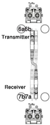
Figure 3. One Way Configuration
⑦ Receiver fiber optic connectors and LEDs —
WARNING: These units output continuous invisible light, which may be harmful to the eyes; use with caution. For additional safety, plug the attached dust caps into the optical transceivers when the fiber cable is unplugged.
NOTES: • You can connect the transmitter to one or more receivers in one of three ways:
- One way (transmitter to receiver) only — Connect a fiber cable to connector ⑦a from transmitter connector ⑥a only (see figure 3).
- Two way (transmitter to receiver and return) — Connect a fiber cable to connector 7a from transmitter connector 6a and a fiber cable from connector 7b back to the transmitter connector 6b (see figure 4.)
- One way (transmitter to receiver) with daisy chain (receiver to receiver) — Connect a fiber cable from a fiber optic source to connector ⑦ and another cable from connector ⑦ to connector ⑦ on the next receiver in the daisy chain (see figure 5.) Set each receiver in the daisy chain to daisy chain mode (via an SIS command for the PowerCage FOX Rx receiver.) Up to 10 properly-configured receivers can be connected in a daisy chain to a single transmitter.
- See the transmitter fiber connector NOTES on the previous page, which also apply to these connectors.

flowchart
graph LR
    A["From Transmitter or Daisy-Chained Receiver"] --> B["7a"]
    B --> C["Receiver"]
    C --> D["7b"]
    D --> E["Receiver"]
    style A fill:#f9f,stroke:#333
    style E fill:#f9f,stroke:#333
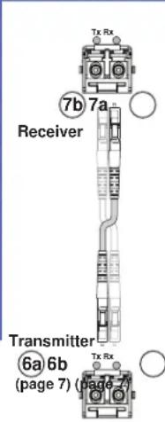
Figure 4. Two Way Configuration
Figure 5. Daisy Chain Configuration
7a Rx (required) — For all one-way video, audio, and serial communications from the transmitter to the receiver, connect a fiber optic cable to the Rx LC connector.
Connect the free end of this fiber optic cable to the Tx connector on the PowerCage FOX Tx transmitter (item 📄 on the previous page) or to any other compatible Extron fiber optic device.
⑦b Tx (optional) — Connect a fiber optic cable to the Tx LC connector for either of the following functions:
Normal configuration — For all one-way return serial communications from the receiver to the Rx connector on the transmitter (see figure 5.)
Daisy chain configuration — For daisy-chained video, audio, and serial communications to the Rx connector on another receiver (see figure 6.)
NOTE: The Tx connector emits light in either case and the Rx port receives light.
Connect the free end of this fiber optic cable to either:
- The Rx connector on the PowerCage FOX Tx transmitter (item 📄b on the previous page) or to any other compatible Extron fiber optic device
- The Rx connector on another receiver in the daisy chain.
Tx and Rx LEDs — When lit, the link is active (light is received).
⑧ HDMI output connector — Connect a video display to this HDMI connector. See "HDMI connectors" on the next page for pin assignments and to use the LockIt HDMI Cable Lacing Bracket to secure the connector to the receiver.
⑨ Audio output connector (receivers) — This 5-pole, 3.5 mm captive screw connector outputs the transmitted, unamplified, line level audio. Connect audio devices, such as an audio amplifier or powered speakers. See "Audio output connector" on page 12 to wire a captive screw connector for the appropriate output type and impedance level.
10 Audio switch — This switch mutes (Off) and unmutes (On) the embedded audio output on the HDMI output connector. The audio on the captive screw audio output always remains active regardless of the setting of this switch.
⑪ Signal LEDs — These indicators light when the transmitter or receiver senses that the associated signal is input (transmitter) or received on the fiber optic cable (receiver).


• HDMI — The unit is sensing an HDMI input signal.
• HDCP — The input signal is HDCP encrypted.
- Audio — The unit is sensing an audio input signal above -35 dBV. The LED turns off if the audio signal level drops below the threshold for 10 seconds.
⑫ Power LED — This LED lights to indicate that power is applied to the unit through the PowerCage backplane.
Making Connections
HDMI connectors
Figure 6 defines the pinout for the HDMI protocol.

HDMI
Type A Receptacle

HDMI
Type A Plug
| Pin | Signal | Pin | Pin Signal | Signal | |
| 1 | TMDS data 2+ | 7 | TMDS data 0- | 13 | CEC control |
| 2 | TMDS data 2 shield | 8 | TMDS data 0 shield | 14 | Reserved (NC) |
| 3 | TMDS data 2- | 9 | TMDS data 0- | 15 | SCL |
| 4 | TMDS data 1+ T | TMDS clock+ | 16 | SDA | |
| 5 | TMDS data 1 shield | 11 | TMDS clock shield | DDC / CEC Ground | |
| 6 | TMDS data 1- | 12 | TMDS clock- +5 | V power | |
| 19 | Hot plug detect | ||||
Figure 6. HDMI Connector
HDMI signals run at a very high frequency and are especially prone to errors caused by bad video connections, too many adapters, or excessive cable length. To avoid the loss of an image or jitter, follow these guidelines:
- Do not exceed 16.4 feet (5 meters) on the input of the PowerCage FOX HDMI transmitter or the output of the PowerCage FOX HDMI receiver.
- Use only the cable designed for HDMI signals that is supplied by Extron.
- Limit or avoid the use of adapters.
- Use only cables specifically intended for HDMI or DVI signals. Use of non-HDMI or non-DVI cables or modified cables can result in a missing video output.
To securely fasten an HDMI cable to a device:
- Plug the HDMI cable into the panel connection (see ① in figure 7).

Figure 7. Installing the LockIt Lacing Bracket
-
Loosen the HDMI connection mounting screw from the panel enough to allow the LockIt lacing bracket to be placed over it (②). The screw does not have to be removed.
-
Place the LockIt lacing bracket on the screw and against the HDMI connector, then tighten the screw to secure the bracket (③).
ATTENTION: Do not overtighten the HDMI connector mounting screw. The shield to which it fastens is very thin and can easily be stripped.
- Loosely place the included tie wrap around the HDMI connector and the LockIt lacing bracket as shown (④).
- While holding the connector securely against the lacing bracket, use pliers or a similar tool to tighten the tie wrap, then remove any excess length (⑤).
RS-232 connectors
The RS-232 Over Fiber port is for transmission of serial signals, such as projector control signals, between the transmitter and receiver.
The Remote RS-232 port is for remote control of the transmitter and receiver. The protocol for the Remote RS-232 port is as follows:
• 9600 baud • no parity • 8 data bits
- 1 stop bit
- no flow control

Figure 8. RS-232 Over Fiber Connector
NOTE: The length of exposed wires is critical. The ideal length is 3/16 inch (5 mm).
- Longer bare wires can short together.
- Shorter wires are not as secure in the connectors and could be pulled out.
Alarm outputs connectors

Figure 9. Alarm Connector
NOTE: The length of exposed wires is critical (see the RS-232 connectors NOTE on the previous page).
Audio output connector
See figure 10 to properly wire a captive screw output connector. The connector is included with transmitter, but you must supply the audio cable. Use the supplied tie-wrap to strap the audio cable to the extended tail of the connector.

Figure 10. Captive Screw Connector Wiring for Stereo Audio Output
ATTENTION: For unbalanced audio, connect the sleeves to the ground contact. DO NOT connect the sleeves to the negative (-) contacts.
NOTE: The length of exposed wires is critical (see the RS-232 connectors NOTE on the previous page).
Transmitter Side Panel Controls
The following features are on the PowerCage HDMI Tx transmitter, and are accessible though the cut on the left side of the module enclosure (see figure 11).

Figure 11. Transmitter Side Panel Controls
① DIP switches —
- Switch 2 (Audio) — This switch selects which audio input, the audio embedded in the HDMI input or the analog audio, is sent to the receiver. On (left) selects the digital (embedded) audio and off (right) selects the analog audio.
- Switch 1 (50 Hz or 60 Hz) — This switch selects the vertical refresh rate of the resolution selected by the EDID Minder hex switch (item ②). On (left) selects the 50 Hz rate and off (right) selects the 60 Hz refresh rate.
② EDID Minder hex switch — Set this switch to one of the positions below to select the source of the DDC or a specific resolution.
• Position 0 — Not applicable
- Position 1 — The EDID is selected via one of the serial ports in the system using an SIS command or the FOX Extenders Control Program.
- Position 2 - F — Specify a resolution. The table below identifies the switch positions and the associated resolutions.
| Pos. Source or resolution Pos. Resolution Pos. Resolution | |||||
| 0 Not applicable 6 1280 x 800 C 1600 x 1200 | |||||
| 1 RS-232 7 1280 x 1024 | D 1680 x 1050 | ||||
| 2 | 800 x 600 | 8 | 1360 x 768 | E | 1920 x 1080 (1080p) |
| 3 | 1024 x 768 9 1366 x 768 | F 1920 x 1200 | |||
| 4 | 1280 x 720 (720p) A 1400 x 1050 | ||||
| 5 | 1280 x 768 B 1440 x 900 | ||||
PowerCage Front Panel Port, Control, and Indicators
The following features are on the front panel of the PowerCage enclosure (see figure 12).
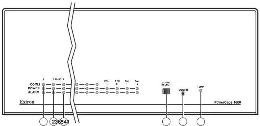
Figure 12. PowerCage Front Panel Features
① Comm LED (16 board locations) — This LED lights to indicate that the board at this location is selected for connection to the Configuration port (item ⑤). Repeatedly press the Comm Select button (item ④) as necessary to select the desired board.
② Power LED (all locations) — This LED lights to indicate that power is applied to the device at this location.
③ Alarm LED (16 board locations) — This LED lights to indicate that light is not received on the Rx connector of the board at this location.
Alarm LED (2 PS locations) — This LED lights to indicate that the power supply has failed or is out of tolerance.
Alarm LED (2 Fan locations) — This LED lights to indicate that the fan has failed.
④ Comm Select button — Repeatedly press this button as necessary to select the desired board for connection to the Configuration port (item ⑤). The Comm LED (item ①) for the selected board lights.
⑤ Configuration port — This 2.5 mm mini stereo jack serves the same serial communications function as the Remote RS-232 port on the transmitter or receiver board, but is easier to access than the ports on the boards after the units have been installed and cabled. The 9-pin D to 2.5 mm mini jack TRS RS-232 cable, included with the PowerCage enclosure, but also available separately, part number 70-335-01 (see figure 13), can be used for this connection.

| 9-pin D Connection TRS Plug | |
| Pin 2 Rx line on the computer Tip | |
| Pin 3 Tx line on the computer Ring | |
| Pin 5 Signal ground on the computer Sleeve |
Figure 13. 9-pin TRS RS-232 Cable
NOTES: This port is for remote control of the transmitter or receiver, not for the over fiber RS-232 link. This port parallels the Remote RS-232 ports on the boards. If an active front panel configuration connection is made, the Remote RS-232 port on the board becomes inactive.
- The maximum distances from the transmitter or receiver to the controlling device can vary up to 200 feet (61 m). Factors such as cable gauge, baud rates, environment, and output levels (from the unit and the controlling device) all affect transmission distance. Distances of approximately 50 feet (15 m) are typically not a problem. In some cases, the unit may be capable of serial communications via RS-232 up to 250 feet (76 m) away.
This port is RS-232 only, with the following protocols:
9600 baud
• 1 stop bit
- no parity - no flow o
- 8 data bits
- no flow control
⑥ Temp LED — This LED lights to indicate that the temperature within the PowerCage enclosure is dangerously high (above 167 °F [75 °C]) and that equipment damage is imminent.
Operation
After the transmitter, all receivers, and their connected devices are powered up, the system is fully operational. If any problems are encountered, verify that the cables are routed and connected properly, and that all display devices have identical resolutions and refresh rates. If your problems persist, call the Extron S3 Sales & Technical Support Hotline (see the contact numbers on the last page of this guide for the Extron office nearest you.)
To take advantage of the various adjustments and test patterns available in the PowerCage FOX, you need to connect a computer or other RS-232 capable device to the Remote/RS-232 port on the unit that provides the function or to the front panel Configuration port and operate using either SIS commands or the FOX Extenders Control Program on a computer running Windows.
Remote Control
This section describes the remote control operation of the PowerCage FOX HDMI, including:
- Serial Ports
• Simple Instruction Set Control
• FOX Extenders Control Program
Serial Ports
The transmitter and receiver boards each have an RS-232 serial port on a 3 pins of a 5-pin captive screw connector that can be connected to a host device (see item ④ on page 6).
The PowerCage enclosure has a Configuration port, a 2.5 mm mini stereo jack, that parallels the board ports (see item ⑤ on page 15).
These serial ports make serial control of the transmitter and receiver possible, using devices such as a computer running the Extron DataViewer or MicroSoft HyperTerminal utility or a control system.
The protocol for all ports is as follows:
9600 baud
- no parity
- 8 data bits
- 1 stop bit
- no flow control
NOTES: For each unit, the Remote RS-232 port is active only if the PowerCage Configuration port is not active. If an active Configuration port connection is made, the Remote RS-232 port for that board becomes inactive. RS-232 commands and Windows-based control program functions are transmitter- or receiver-specific or may have different responses depending on the unit connected. You must connect to the appropriate device for the command or function to work properly or to get the expected response.
Simple Instruction Set Control
Host-to-unit Instructions
SIS commands consist of one or more characters per field. No special characters are required to begin or end a command character sequence. When a command is valid, the unit executes the command and sends a response to the host device. All responses from the unit to the host end with a carriage return and a line feed (CR/LF = ←), which signals the end of the response character string. A string is one or more characters.
Unit-initiated Messages
When a local event, such as an equipment power-up, occurs, the unit responds by sending a message to the host. The unit-initiated messages are listed below:
(c) Copyright 20nn, Extron Electronics PowerCage FOX Tx HDMI, Vn.nn, 70-889-nn
- or -
(c) Copyright 20nn, Extron Electronics PowerCage FOX Rx HDMI, Vn.nn, 70-889-nn
The connected unit issues the appropriate copyright message (above) when it first powers on. Vn.nn is the firmware version number; 70-889-nn is the part number of the connected unit.
Reconfig
The unit sends the Reconfig message whenever the video input signal to the transmitter is changed.
1Lnknn•2Lnknn•Vidnn•Audnn←
The unit sends the status message whenever a change in the fiber link and video and audio connection occurs. nn is the link or input status, where = link or input not detected, 1 = link or input detected, and - - = not applicable for this unit.
EmbedAudn←
The unit sends the Embedded audio message whenever a change in the position of the receiver HDMI Audio switch occurs. n is the switch position, where = embedded audio is muted and 1 = unmuted.
Error Responses
When the unit receives a valid SIS command, it executes the command and sends a response to the host device. If the unit is unable to execute the command because the command is invalid or it contains invalid parameters, the unit returns an error response to the host. The error response codes are:
E10 - Invalid command
E11 - Invalid preset number
E13 - Invalid parameter
E14 - Invalid command for this configuration
Using the Command and Response Tables
The command and response tables begin on the next page. Either uppercase or lower case letters are acceptable in the command field except where indicated for the audio level (gain and attenuation) commands. Symbols are used throughout the table to represent variables in the command and response fields. Command and response examples are shown throughout the table. The ASCII to HEX conversion table below is for use with the command and response table.

Symbol definitions for transmitter SIS commands
← = Carriage return/line feed
← = Carriage return (no line feed)
| = Pipe (can be used interchangeably with the ← character)
- = space
Esc = Escape key
W = Can be used interchangeably with the Esc character
X1 = EDID hex switch position
X2 = Refresh rate
X3 = EDID
X4 = Native resolution
X5 = EDID record
X6 = Audio gain adjustment range
X7 = Audio level adjustment range
[X8] = Audio attenuation adjustment range
X9 = Mode switch position and enable or disable status
X10 = Link and input status
X11 = Internal temperature
X12 = Transmission mode
X13 = Firmware version
X14 = Sync frequency
= N / A 8 = 1360× 768
01 = RS-232 control 09 = 1366 x 768
∅2 = 800 x 600 1∅ = 1400 x 1050
03 = 1024 × 768 11 = 1440 × 900
04 = 720p^* 12 = 1600 × 1200
05 = 1280 x 768 13 = 1680 x 1050
06 = 1280 x 800 14 = 1080p*
07 = 1280 x 1024 15 = 1920 x 1200
720p and 1080p also include a block for embedded audio; all other positions are video only
1 = 50 Hz 2 = 60 Hz
See the table on page 20.
Resolution and rate in an easily-viewed format, such as "800x600@60Hz".
128 or 256 bytes
∅∅ to 1∅
-18 to +10 (in 1.0 dB steps)
∅∅ to 18
= off (down) or disable 1 = on (up) or enable
= link or input not detected 1 = link or input detected
nnnF•nnC
SM = singlemode MM = multimode
V.VV
xxx.xx (frequency in kHz [H] or Hz [V])
Command and Response Table for Transmitter SIS Commands
| Command ASCII Command (Host to Unit) | Response (Unit to Host) | Additional Description | |
| Switch status | |||
| Request EDID and refresh rate switch positions | EscStat← | EdidMdrX1•VrateX2← | |
| Example: | EscStat← | EdidMdr15•Vrate2← | EDID switch is set to 15 (1080p) and the vertical rate switch is set to 2 (60 Hz). |
| Request EDID switch position | Esc2Stat←X1← | ||
| Request Refresh rate switch position | Esc3Stat←X2← | ||
EDID minder
| NOTES: • The table below the commands defines the value of each EDID value.• The side panel EDID minder rotary switch on the transmitter must be in position 1 for the variables to be changeable via an SIS command. The unit returns the E14 error if the switch is in other than position 1. | |||
| Set EDID resolution and refresh rate | EscA × 3EDID← | EdidA × 3← | Assign an EDID value of × 3. |
| Example: | EscA58EDID← | Edid58← | Assign an EDID value of 720p at 60 Hz (the default resolution and rate). |
| View assigned EDID | EscAEDID← × 3← | The assigned EDID value is × 3. | |
| Show native EDID value | EscNEDID← × 4← | Show the native resolution of the display connected to the receiver. | |
| Import EDID | EscI EDID← × 5 | EdidI← | |
| X3 | Value | X3 | Value | X3 | Value | X3 | Value | X3 | Value |
| ∅∅ | User captured EDID | ||||||||
| DVI Pro values (with HDMI-to-DVI adapters) | |||||||||
| ∅1 | 800x600 @ 50 Hz | ∅7 | 1280x768 @ 50 Hz | 13 | 1360x768 @ 50 Hz | 19 | 1440x900 @ 50 Hz | 25 | 1680x1050 @ 50 Hz |
| ∅2 | 800x600 @ 60 Hz | ∅8 | 1280x768 @ 60 Hz | 14 | 1360x768 @ 60 Hz | 2∅ | 1440x900 @ 60 Hz | 26 | 1680x1050 @ 60 Hz |
| ∅3 | 1024x768 @ 50 Hz | ∅9 | 1280x800 @ 50 Hz | 15 | 1366x768 @ 50 Hz | 21 | 1600x900 @ 50 Hz | 27 | 1920x1080 @ 50 Hz |
| ∅4 | 1024x768 @ 60 Hz | 1∅ | 1280x800 @ 60 Hz | 16 | 1366x768 @ 60 Hz | 22 | 1600x900 @ 60 Hz | 28 | 1920x1280 @ 60 Hz |
| ∅5 | 1280x720 @ 50 Hz | 11 | 1280x1024 @ 50 Hz | 17 | 1400x1050 @ 50 Hz | 23 | 1600x1200 @ 50 Hz | 29 | 1920x1200 @ 50 Hz |
| ∅6 | 1280x720 @ 60 Hz | 12 | 1280x1024 @ 60 Hz | 18 | 1400x1050 @ 60 Hz | 24 | 1600x1200 @ 60 Hz | 3∅ | 1920x1200 @ 60 Hz |
| HDMI PC values, all with 2-channel embedded audio | |||||||||
| 31 | 1024x768 @ 50 Hz | 36 | 1280x800 @ 60 Hz | 41 | 1366x768 @ 50 Hz | 46 | 1440x900 @ 60 Hz | 51 | 1680x1050 @ 50 Hz |
| 32 | 1024x768 @ 60 Hz | 37 | 1280x1024 @ 50 Hz | 42 | 1366x768 @ 60 Hz | 47 | 1600x900 @ 50 Hz | 52 | 1680x1050 @ 60 Hz |
| 33 | 1280x768 @ 50 Hz | 38 | 1280x1024 @ 60 Hz | 43 | 1400x1050 @ 50 Hz | 48 | 1600x900 @ 60 Hz | 53 | 1920x1200 @ 50 Hz |
| 34 | 1280x768 @ 60 Hz | 39 | 1360x768 @ 50 Hz | 44 | 1400x1050 @ 60 Hz | 49 | 1600x1200 @ 50 Hz | 54 | 1920x1200 @ 60 Hz |
| 35 | 1280x800 @ 50 Hz | 4∅ | 1360x768 @ 60 Hz | 45 | 1440x900 @ 50 Hz | 5∅ | 1600x1200 @ 60 Hz | ||
| HDMI HDTV values, all with 2-channel embedded audio | |||||||||
| 55 | 480p @ 60 Hz | 57 | 720p @ 50 Hz | 59 | 1080i @ 50 Hz | 61 | 1080p @ 50 Hz | ||
| 56 | 576p @ 50 Hz | 58* | 720p @ 60 Hz | 6∅ | 1080i @ 60 Hz | 62 | 1080p @ 60 Hz | ||
* Default value
| NOTE: | 1 = EDID hex switch position | = N/A | 4 = 1280x720* (720p) | 8 = 1360 x 768 | 12 = 1600 x 1200 |
| 1 = RS-232 control | 5 = 1280 x 768 | 9 = 1366 x 768 | 13 = 1680 x 1050 | ||
| 2 = 800 x 600 | 6 = 1280 x 800 | 10 = 1400 x 1050 | 14 = 1920x1080p* (1080p) | ||
| 3 = 1024 x 768 | 7 = 1280 x 1024 | 11 = 1440 x 900 | 15 = 1920 x 1200 | ||
| * 720p and 1080p also include a block for embedded audio; all other positions are video only | |||||
| 2 = Refresh rate | 1 = 50 Hz | 2 = 60 Hz | |||
| 3 = EDID | See the table above. | ||||
| 4 = Native resolution | Resolution and rate in an easily-viewed format, such as “800x600@60Hz” | ||||
| 5 = EDID record | 128 or 256 bytes | ||||
| Command ASCII Command (Host to Unit) | Response (Unit to Host) | Additional Description | |||
| Audio input gain and attenuation | |||||
| NOTES: The set gain (G) and set attenuation (g) commands are case sensitive. The increment level, decrement level, and show level are not case sensitive.When the controlling PC is connected to the receiver, the PowerCage FOX can perform this command only if the receiver-Tx-to-transmitter-Rx fiber cable is connected. The unit returns the E14 error if the Rx fiber is not connected. | |||||
| Set input audio gain to a +dB valueExample: 2G Set input audio attenuation to a -dB valueIncrement input level +G Example: +G Decrement input level -G Show input level G | X6G Aud X7← | Set the input level to X7 dB (gain).Set the input level to +2 dB (gain).Set the input level to X7 dB (attenuation).Increase the audio level by 1 dB.Increment the input level from +2 dB to +3 dB.Decrease the audio level from 0 dB to -1 dB. | |||
| X8g Aud X7← | |||||
| +G AudX7← | |||||
| +G Aud+∅3.∅← | |||||
| -G Aud-∅1.∅← | |||||
| G X7← | |||||
| Plus mode transmission | |||||
| NOTE: Plus mode forces the transmitter to emulate a PowerCage FOX DVI Plus or FOXBOX DVI Plus transmitter. | |||||
| Enable Plus mode 81*1# Disable Plus mode 81*∅# View Plus mode 81# | Plus1← Plus∅← X9← | Turn on Plus mode (default).Turn off Plus mode.Show Plus mode status. | |||
| Input reports as an HDCP authorized device | |||||
| HDCP authorized device on HDCP authorized device off View HDCP authorized device status | EscE1HDCP← EscE∅HDCP← EscEHDCP←X9← | HdcpE1← HdcpE∅← | Set the transmitter as an HDCP authorized device.Set the transmitter as not an HDCP authorized device.Show HDCP authorized device status. | ||
| Status requests | |||||
| View link 1 (Tx-to-Rx) status 1S View link 2 (Rx-to-Tx) status 2S View input video status 3S View input audio status 4S View all signal status 5S | X10← X10← X10← X10← X10← SigI X10→SigO X10→HdcpI X10→HdcpO X10← | Report the status of the HDMI input, HDMI output, HDCP encoding on the input, and HDCP encoding on the output.Report the status of the HDMI input and HDMI output (always -- for a transmitter).Report the status of the HDCP encoding on the input and HDCP encoding on the output.Show temperature in degrees Fahrenheit and Celsius. | |||
| View HDMI signal status 6S | SigI X10→SigO X10← | ||||
| View HDCP status 7S | HdcpI X10→HdcpO X10← | ||||
| View temperature 20S | X11F→X11C← | ||||
| NOTE: X6 = Audio gain adjustment range X7 = Audio level adjustment range X8 = Audio attenuation adjustment range X9 = Enable or disable status X10 = Link and input status X11 = Internal temperature | ∅∅ to 1∅ -18 to +1∅ (in 1.0 dB steps) ∅∅ to 18 ∅ = off (down) or disable ∅ = link or input not detected nnnF→nnC | 1 = on (up) or enable 1 = link or input detected | |||
| Information requests | |||||
| Information request | I | 1Lnk 10 •2Lnk 10 •Vid 10 •Aud 10 • 12 •Tx← | The unit responds with the current status (signal detected) of optical link 1, optical link 2, the video input, and the audio link; the fiber optic transmission mode (singlemode or multimode); and the device type (Tx). | ||
| Show firmware version | Q | 13 | |||
| Example: | Q | 1.23← | The factory-installed firmware version is 1.23 (sample value only). | ||
| Request part number | N | 70-889-nn← | See “Part Numbers” in the “Reference Information” section on page 40. | ||
| Input sync detection | 1LS | 14 horizontal, 14 vertical← | Shows horizontal frequency in kHz and vertical frequency in Hz.000.0,000.0if no signal is detected. | ||
| Resets | |||||
| Reset audio | EscZA← | Zpa← | Reset audio setting to default levels (0 dB gain). | ||
| System reset | EscZXXX← | Zpx← | Reset all settings to factory defaults. | ||
| NOTE: X10= Link status X12= Transmission mode X13= Firmware version v.vv X14= Sync frequency | ∅ = light or signal input not detected SM = singlemode xxx.xx (frequency in kHz [H] or Hz [V]) | 1 = light or signal detected MM = multimode | |||
Symbol definitions for receiver SIS commands
← = Carriage return/line feed
← = Carriage return (no line feed)
| = Pipe (can be used interchangeably with the ← character)
- = space
Esc = Escape key
W = Can be used interchangeably with the Esc character
X9 = Mute or auto memory status and enable or disable status
X10 = Link and input status
X11 = Internal temperature nnnF•nnC
X12 = Transmission mode
X13 = Firmware version
X14 = Sync frequency
X15 = Horizontal and vertical position
X16 = Memory preset number
X17 = Test pattern
X18 = Rx link and daisy chain enable
X19 = Video bit depth
X20 = Video delay (0 plus six steps at 0.25 seconds per step)
X21 = Switch position
= off or disable 1 = on or enable
∅ = link or input not detected 1 = link or input detected
SM = singlemode MM = multimode
V.VV
xxx.xx (frequency in kHz [H] or Hz [V])
000 through 255
01 through 30
∅ = none 2 = grayscale
1 = color bars 3 = alternating pixels
= disable 2 = daisy chain enable
1 = return link enable
= auto 1 = 8-bit
∅ = 0 second
1 = 0.25 second 4 = 1.0 second
2 = 0.5 second (default) 5 = 1.25 second
3 = 0.75 second 6 = 1.5 second
∅ = off (right) 1 = on (left)
Command and Response Table for Receiver SIS Commands
| Command | ASCII Command (Host to Unit) | Response (Unit to Host) | Additional Description |
| Video mute | |||
| Mute output | 1B | Blk1← | Blank the video output. |
| Unmute output | ∅B | Blk∅← | Output video. |
| Show video mute status | B | X9← | Video mute status is X9. |
| Horizontal shift | |||
| Set a horizontal position | X15H | HphX15← | Set horizontal centering to X15. |
| Increment position | +H | HphX15← | Shift the image one pixel to the right. |
| Decrement position | -H | HphX15← | Shift the image one pixel to the left. |
| Show position | H | X15← | |
| Vertical shift | |||
| Set a vertical position | X15/ | VphX15← | Set vertical centering to X15. |
| Increment position | +/ | VphX15← | Shift the image down one line. |
| Decrement position | -/- | VphX15← | Shift the image up line. |
| Show position | / | X15← | |
| List sync frequency | |||
| View input frequency | 1LS | X14horizontal, X14vertical← | Shows horizontal frequency in kHz and vertical frequency in Hz.000.0,000.0 if no signal is detected. |
| Memory presets | |||
| Save preset | X16, | SprX16← | Command code is a comma. |
| Recall preset | X16. | RprX16← | Command code is a period. |
| NOTE: X9 = Mute and auto memory status∅ = off 1 = onX14 = Horizontal and vertical position∅00 through 255X15 = Sync frequencyxxx.xx (frequency in kHz [H] or Hz [V])X16 = Memory preset number∅1 to 30 | |||
| Command ASCII Command (Host to Unit) | Response (Unit to Host) | Additional Description | |
| Auto memory | |||
| Disable auto memory | 55*0# | Img0← | |
| Enable auto memory | 55*1# | Img1← | |
| Show auto memory status | 55# | X9← | |
| Audio mute | |||
| Mute the audio | 1Z | Amt1← | Silence the audio output of the receiver. |
| Unmute the audio | ∅Z | Amt0← | The receiver outputs audio. |
| Show audio mute status | Z | X9← | Audio mute status is X9. |
| Test patterns | |||
| NOTE: You must have a video input connected to the transmitter and the transmitter-Tx-to-receiver-Rx fiber cable connected for the receiver to output a selected test pattern. The test pattern turns off if the input signal rate changes or is disconnected or if power is removed. | |||
| Output color bars | 1J | Tst1← | Set the receiver to output the color bars test pattern. |
| Output grayscale | 2J | Tst2← | Set the receiver to output the grayscale test pattern. |
| Output alternating pixels | 3J | Tst3← | Set the receiver to output the alternating pixels test pattern. |
| Turn test pattern off | ∅J | Tst0← | Set the receiver to output the input video (no test pattern is selected). |
| Show test pattern status | J | X17← | |
| Disable and enable return link and daisy chain | |||
| NOTE: The disable return link function is primarily used and recommended when the transmitting device is a FOX 500 DA6 and the receiver is connected to any of outputs 2 through 6 on the DA. | |||
| Disable return link | 66*∅*∅# | Rle*∅*∅← | Disable link 2. |
| Enable return link to transmitter | 66*∅*1# | Rle*∅*1← | Enable link 2 (default setting). |
| Enable daisy chain | 66*∅*2# | Rle*∅*2← | Enable receiver daisy chain mode. |
| Show return link and daisy chain status | 66*∅# | ∅*X18← | |
| Video bit depth | |||
| Set video bit depth to auto | EscV∅BITD← | BitdV∅← | |
| Force video to 8-bit depth | EscV1BITD← | BitdV1← | |
| View video bit depth | EscVBITD←X19← | ||
| HDCP notification | |||
| Enable notification | EscN1HDCP←HdcpN1← | ||
| Disable notification | EscN∅HDCP←HdcpN∅← | ||
| View notification status | EscNHDCP← | X9← | |
| NOTE: X9 = Mute and auto memory status X14 = Horizontal and vertical position X17 = Test pattern X18 = Rx link and daisy chain enable X19 = Video bit depth | ∅ = off 000 through 255 ∅ = none 1 = color bars ∅ = disable ∅ = auto | 1 = on 2 = grayscale 3 = alternating pixels 1 = return link enable 2 = daisy chain enable 1 = 8-bit | |
| Video shutdown delay | |||
| NOTES: The Set Video Delay command delays the digital video to help monitors sync correctly during an input rate change.Only video is delayed. Embedded audio is not delayed. | |||
| Set delay | 3*X20# Dly | X20← | Delay video by an interval of X20. |
| Example: | 3*3# | Dly3← | Delay video by an interval of 0.75 seconds (3 x 0.25 seconds). |
| View delay | 3# | X20← | |
| Switch and signal status requests | |||
| Request Audio switch status | EscStat← | EmbedAudX21← | Show the position of the Audio switch:∅ = off (embedded audio is muted) or 1 = on (unmute). |
| NOTE: The audio on the captive screw audio output always remains active regardless of the setting of this switch. | |||
| Check audio embed | Esc5Stat←X10← | Show if audio is embedded in the video stream:∅ = not detected or 1 = detected. | |
| View link 1 (Tx-to-Rx) status | 1S | X10← | |
| View link 2 (Rx-to-Tx) status | 2S | X10← | |
| View input video status | 3S | X10← | |
| View input audio status | 4S | X10← | |
| View all signal status | 5S | SigI X10•SigO•HdcpI X10•HdcpO X10← | Report the status of the HDMI input, HDMI output, HDCP encoding on the input, and HDCP encoding on the output. |
| View HDMI signal status | 6S | SigI X10•SigO--← | Report the status of the HDMI input and HDMI output (always -- for a transmitter). |
| View HDCP status | 7S | HdcpI X10•HdcpO X10← | Report the status of the HDCP encoding on the input and HDCP encoding on the output. |
| View temperature | 20S | X11F•X11C← | Show temperature in degrees Fahrenheit and Celsius. |
| Information requests | |||
| Information request | I | 1Lnk X10•2Lnk X10•Vid X10•Aud X10•X12•Rx← | The unit responds with the current status (signal detected) of optical link 1, optical link 2, the video input, and the audio link; the fiber optic transmission mode (singlemode or multimode); and the device type (Rx). |
| Show firmware version | Q | X13← | |
| Example: | Q | 1.23← | The factory-installed firmware version is 1.23 (sample value only). |
| Request part number | N | 70-889-nn← | nn = 22 (singlemode) or 21 (multimode). |
| Resets | |||
| Reset memory presets | EscZG← | Zpg← | Reset (erase) all memory presets. |
| System reset | EscZXXX← | Zpx← | Reset all settings to factory defaults. |
| NOTE: X9 = Mute and auto memory statusX21 = Switch positionX10 = Link status ∅ = light or signal input not detectedX20 = Video delay(0 plus six steps at 0.25 seconds per step)X13 = Firmware versionX11 = Internal temperature | ∅ = off∅ = off (right)1 = light or signal detected∅ = 0 second1 = 0.25 second2 = 0.5 second (default)v.vvnnnF•nnC | 1 = on1 = on (left)3 = 0.75 second 5 = 1.25 second4 = 1.0 second 6 = 1.5 second | |
FOX Extenders Control Program
The Extron FOX Extenders program, which communicates with the transmitter and receiver pair, via the Remote RS-232 port of either unit or the PowerCage Configuration port, provides an easy way to operate the pair.
The program is compatible with Windows 2000, Windows XP, Windows 7, or later. Updates to this program can be downloaded from the Extron website (www.extron.com).
Installing the Software
The program is contained on a DVD. To install the software, insert the DVD into the drive. The Extron software DVD window should appear automatically. If it does not self-start, run Launch.exe from the DVD. Click the Software tab, scroll to the desired program, and click Install. Follow the instructions that appear on the screen. By default, the installation creates a C:\Program Files\Extron\FOX_Extenders directory, and it places four icons into a group folder named "Extron Electronics\FOX Extender Control Program" The four installed icons are:
- Check for FOX Extenders updates
FOX Extenders
FOX Extenders Help - Uninstall FOX Extenders
Starting the Program
Start the Extron FOX Extenders program as follows:
- Click Start > Programs > Extron Electronics > FOX Extenders Control Program > FOX Extenders.

The Communication Setup window appears (see figure 14).

Figure 14. Communication Setup Window
- Select the Com port to which your transmitter or receiver is connected. Click OK. The FOX Extenders Control Program window appears (see figure 15).

Figure 15. FOX Extenders Control Program Window
NOTES: • Figure 15 is an amalgam of program displays. Some controls and displays are available when connected to the transmitter only and some when connected to the receiver only. These functions are identified in the descriptions that follow.
- Only one fiber optic cable, transmitter-Tx-to-receiver-Rx, is required for serial command transmission. But, if you connect only one fiber optic cable, the transmitter does not receive reports from the controlled device. For the transmitter to receive responses from the controlled device, you must install two fiber optic cables and leave link 2 enabled (via an SIS command to the receiver or using the FOX Extenders Control Program).
Status area

Figure 16. Status Area
The status area provides indications of the connection status.
- HDMI indicator — This indicator is green when the transmitter detects a sync signal on its HDMI video input
- Audio indicator — This indicator is green when the transmitter detects a low level audio signal for a short period. This indicator goes dark if the audio signal drops below the minimum threshold for a short period.
- Link 1 indicator — This indicator is green when the receiver detects light on the fiber optic cable connected to the Tx port.
NOTE: The receiver detects the transmitter-Tx-to-receiver-Rx light. It reports the status to the transmitter via the optional Rx cable. If the PC is connected to the transmitter and either the secondary (receiver-Tx-to-transmitter-Rx) cable is not connected in your system or the receiver is in the daisy chain mode, the Link 1 indicator in the control program does not show green (detected), whether the receiver detects the link or not.
- Link 2 (Optional) indicator — This indicator is green when the transmitter detects light on the fiber optic cable connected to the Rx port.
NOTE: The transmitter detects the receiver-Tx-to-transmitter-Rx light. It reports the status to the receiver via the Tx cable. If the PC is connected to the receiver and either the primary (transmitter-Tx-to-receiver-Rx) cable is disconnected or the receiver is in the daisy chain mode, the Link 2 indicator in the control program does not show green (detected), whether the transmitter detects the link or not.
The Status area also shows to which unit the controlling PC is connected, the FOXBOX model (multimode or singlemode), the internal temperature, and the video input frequency. The Other Side entry cannot be read on the FOXBOX HDMI and shows N/A.
Control tab functions
Control I/O Configuration Advanced
Click the Control tab to access the functions described below.
Video Adjustment area
NOTE: The Video Adjustments area controls are available only if your computer is connected to the receiver and an active video input is connected to the transmitter.
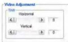
The Video Adjustment area provides slider controls that let you change the Shift Horizontal (position) and Shift Vertical (position).
Audio Adjustment area
NOTE: The Audio Adjustment area controls are available only if your computer is connected to the transmitter.
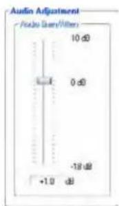
Audio Gain/Attenuation slider — Click and drag the Audio Gain/Attenuation slider control to select the input audio gain or attenuation value, from -18 dB to +10 dB in 1.0 dB increments.
Memory Preset area
NOTE: The Memory Preset area controls are available only if your computer is connected to the receiver.

The Memory Preset area provides a means to save and recall memory presets. Memory presets are stored values of the horizontal and vertical position saved in nonvolatile memory. When the PowerCage HDMI unit is powered down and later powered back up, the settings are available for selection using the Recall button. Saving the settings to a preset using the Save button overwrites the settings previously written to that preset.
Mute area
NOTE: The Mute area controls are available only if your computer is connected to the receiver.

Click the Video Mute On or Off radio button, the Audio Mute On or Off radio button, or both in the Mute area to turn the video and audio mutes on and off.
I/O Configuration tab functions
Click the I/O Configuration tab to access the functions described below.
Control I/O Configuration Advanced
Output Configuration area
NOTE: The Output Configuration area control is available only if your computer is connected to the receiver.
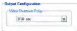
The Video Shutdown Delay setting delays the digital video to help monitors sync correctly during an input rate change. Only video is delayed; embedded audio is not delayed.
HDCP area
NOTE: The HDCP Authorized controls are available only if your computer is connected to the transmitter. The HDCP Notification controls are available only if your computer is connected to the receiver.
Both sets of radio buttons cannot be available for selection at the same time.
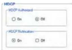
HDCP Authorized radio buttons — The HDCP Authorized setting allows a user to turn off HDCP communication on a discrete input. This setting is useful for devices such as Mac computers, iPhones, iPads, and some Windows 7 sources that always encrypt their output if the downstream sink is capable of HDCP. By not allowing HDCP signals on an input, most content from these sources can be passed as a non-encrypted signal to analog and digital video outputs. In a video system that has requirements to not transmit HDCP encrypted data (such as non-HDMI FOX Extenders), HDCP support should be turned off at the input to keep the non-HDMI output of the FOX Extender unencrypted.
HDCP Notification radio buttons — The HDCP notification function in the receiver enables a connected display to show a green or black screen if the transmitted HDMI video is HDCP encrypted and the display is not HDCP capable.
Assigned EDID area
NOTE: The Assigned EDID area control is available only if your computer is connected to the transmitter and EDID Minder hex switch, on the side panel of the transmitter, is in position 1. If the hex switch is not in position 1, the Assigned EDID area advises you "To change EDID, set rotary switch from #n to #1."

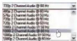
The Assigned EDID area provides a drop-down box that let you manually set the EDID resolution and refresh rate and reports the position of the EDID Minder hex switch.
Plus Mode Transmission area
NOTE: The Plus Mode Transmission radio buttons are available only if your computer is connected to the transmitter.

The Plus Mode Transmission radio buttons allow you to enable and disable Plus mode.
- Enabled forces the transmitter to emulate a PowerCage FOX DVI Plus or FOXBOX DVI Plus transmitter for compatibility with one of four receivers: a PowerCage HDMI Rx, a PowerCage FOX DVI Plus Rx, a FOXBOX HDMI Rx, or a FOXBOX DVI Plus Rx.
- Disabled allows the output of the transmitter to be received by any PowerCage FOX, FOXBOX, and FOX 500 VGA and DVI unit, including the Plus and non-Plus units.
Video Bit Depth area
NOTE: The Video Bit Depth area radio buttons are available only if your computer is connected to the receiver.

The Video Bit Depth radio buttons allow you to force the bit depth to 8 bits or to set it to auto.
Advanced tab functions
Control I/O Configuration Advanced
Click the Advanced tab to access the functions described below.
NOTE: The Advanced functions are available only if your computer is connected to the receiver.
Advanced Configuration area
Link 2 and Daisy Chain radio buttons — Select among the Enable Link 2, Disable Link 2, and
Enable Daisy Chain radio buttons to define the function of the receiver Tx LC connector; either:
- Routing RS-232 over fiber to the transmitter
- No function
- Routing the signal received on the Rx LC connector to the next receiver in a daisy chain.

NOTE: The disable return link function is primarily used and recommended when the transmitting device is a FOX 500 DA6 and the receiver is connected to any of outputs 2 through 6 on the DA.
Auto Memory radio buttons — Select the Auto Memory radio button to automatically apply saved position settings when the sensed input resolution changes.
Test Patterns drop box — Select one of three built-in test patterns; Colorbars, Grayscale, and Alternating Pixels; as necessary to help adjust the color, brightness and contrast, and focus of the display. Select Off to output the video that is input to the transmitter.
NOTES: • You must have a video input connected, the transmitter-Tx-to-receiver-Rx fiber cable connected, and the receiver cannot be in daisy-chain mode for the receiver to output a selected test pattern.
- The test pattern turns off if the input signal rate is changed or disconnected or if power is removed.
Firmware Upgrade
Firmware can be upgraded for each unit via the PowerCage front panel Configuration port using the Extron Firmware Loader utility from the Windows-based control program.
Downloading the firmware from the Web site
To obtain the latest version of firmware for your PowerCage FOX unit:
- Visit the Extron website, www.extron.com, click the Download tab, and then click the Firmware link on the left sidebar menu (see figure 17).

Figure 17. Location of Firmware Upgrade Files
- On the Download Center screen (see figure 18), click the links for the appropriate firmware file or files.
NOTE: There are different files for the transmitter (Tx) and receiver (Rx).

Figure 18. Finding PowerCage FOX Firmware
- Complete the Personal Information form (see figure 19) and click the Download button.
Download Center
Download PowerCage FOX_RX_HDMI_FW1x07.exe
Please provide the following information.

Figure 19. Personal Information Form
TIP: Select the Remember Me checkbox to avoid filling out this form in the future.
- Follow the instructions on the rest of the download screens to download the firmware update from the Extron website, start the Extron Installation Program to extract the firmware file, and place the file in a folder identified in the program window.
NOTE: Note the folder to which the firmware file is saved (see figure 20).

Figure 20. Location of the Firmware File
Loading the firmware to the transmitter and receiver
To load a new version of firmware to your transmitter and receiver, call the Firmware Loader software from within the FOX Extenders Control Program. The serial port on your computer must be connected to the PowerCage front panel Configuration port and the unit to be updated must be selected (see item ④ and item ⑤ in the "PowerCage Front Panel Port, Control, and Indicators" section on page 14).
- In the FOX Extenders Control Program, click the Firmware Loader button (✗) on the tool bar.
NOTE: If the Firmware Loader button does not appear on the tool bar, the Firmware Loader software is not installed. Install it as follows:
a. On the Extron website, click the Download tab.
b. On the Download Center page, click Software on the left sidebar menu.
c. Locate the "Firmware Loader" line and click the Download link at the far right.
d. Follow the instructions on the download screens to save the installer file to your computer.
e. In Windows Explorer or another file browser, locate the Firmware Loader executable file in the file system on your computer and double-click it to open it.
f. Follow the instructions on the Installation Wizard screens to install the Firmware Loader on your computer. Unless you specify otherwise, the installer program places the Firmware Loader file, "FWLoader.exe" in C:\Program Files\Extron\FWLoader.
If the Extron and FWLoader folders do not yet exist in your Program Files folder, the installer creates them.
- If you have not previously updated firmware for the PowerCage FOX unit before, on the Add Device screen (see figure 21), select the RS-232 tab.

Figure 21. Add Device Screen
If you have previously updated firmware for this model, click Cancel. The Firmware Loader window appears. Proceed to step 5.
NOTE: Although the screen also has a TCP/IP tab, the PowerCage FOX unit does not have a LAN port. Do not select the TCP/IP tab.
-
From the drop-down menus on the RS-232 screen, select the appropriate Com port number and baud rate (the default is 9600).
-
Click OK. The Firmware Loader window appears (see figure 22).
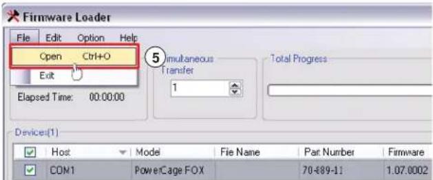
Figure 22. Extron Firmware Loader Window
- Select the PowerCage FOX unit and click File > Open. The Choose Firmware File screen appears (see figure 23).

Figure 23. Choose Firmware File Window
- Navigate to and select the new firmware file. Click Open. The Choose Firmware File window closes.
NOTE: When downloaded from the Extron Web site, the firmware is placed in a subfolder of C:\Program Files\Extron\Firmware.
ATTENTION: The firmware file must have a .S19 extension. Other file types can cause the unit to stop functioning.
- In the Firmware Loader window, click Begin (see figure 24).
The Total Progress and Progress status bars show the progress of the upload. The firmware upload to the unit may take several minutes. Once the status bars have progressed from 0% to 100%, and Status is listed as Completed, the firmware loader utility resets the unit.

Figure 24. Firmware Loader Screen
- Click Exit to close the Firmware Loader.
Reference Information
This section provides the specifications, part numbers, and installation instructions for the PowerCage FOX HDMI.
- Specifications
- Part Numbers
• Installing a Board in the Enclosure
Specifications
NOTES: • The PowerCage FOX HDMI boards are not compatible with the FOX 3G HD-SDI, FOX 3G DVC, or FOX AV models.
- The PowerCage FOX boards are available in singlemode or multimode versions.
- The optional PowerCage FOX boards are class 1 laser products. They meet the safety regulations of IEC-60825, FDA 21 CFR 1040.10, and FDA 21 CFR 1040.11.
Optical specifications — PowerCage FOX boards, interconnection between transmitter and receiver
Number/type.... 1 singlemode or 1 multimode fiber optic input and output per FOX board, up to 8 double space boards per PowerCage enclosure
NOTE: Only one fiber is required to transmit video, audio, and unidirectional data. A second fiber is required to transmit HDMI video with HDCP content or return data for bidirectional control/communication.
Connectors 2 bidirectional LC connectors per FOX board
Operating distance
Singlemode 30 km (18.75 miles) with singlemode (SM) cables with a SM board
Multimode.... 300 m (985') with 62.5 μm OM1 multimode (MM) cable and a MM board
1 km (3280') with 50 μm OM2 multimode (MM) cable and a MM board
2 km (6561') with 50 μm OM3/OM4 2000 MHz bandwidth laser optimized MM cable and a MM board
NOTE: Operating distance is approximate. These are typical distances. The maximum distance may be greater than these typical numbers depending on factors such as fiber type, fiber bandwidth, connector splicing, losses, modal or chromatic dispersion, environmental factors, and kinks.
Nominal peak wavelength.... 850 nm for multimode (MM), 1310 nm for singlemode (SM)
Transmission power, singlemode or multimode
-5 dBm, typical
Maximum receiver sensitivity
Singlemode .... -18 dBm, typical
Multimode.... -12 dBm, typical
Optical loss budget
Singlemode 13 dB, maximum
Multimode.... 7 dB, maximum
Maximum channel data rate...... 4.25 Gbps
Video — PowerCage FOX Tx/Rx HDMI
NOTE: Appropriate HDMI to DVI-D cables or adapters are required for DVI signal input and output.
Maximum data rate.... 4.25 Gbps
Maximum pixel clock.... 165 MHz
Maximum resolution 1920x1200 or 1080p @ 60 Hz, 8-bit color
Formats...... RGB, YCbCr, xvYCC digital video
Standards...... DVI 1.0, HDMI, HDCP 1.1, CEA-861E
Video input — PowerCage FOX Tx HDMI
Number/signal type 1 single link HDMI
Connectors 1 female 19-pin HDMI type A
Video output — PowerCage FOX Rx HDMI
Number/signal type 1 single link HDMI
Connectors 1 female 19-pin HDMI type A
Audio
NOTE: In PowerCage FOX boards, the analog audio signals are digitized in the transmitter, sent through the fiber cable, and converted back to analog audio in the receiver.
Gain
Range.... Adjustable, -18 dB to +10 dB
Default ...... Unbalanced output: -6 dB; balanced output (default): 0 dB
Frequency response.... 20 Hz to 20 kHz, ±0.5 dB
THD + Noise.... 0.10% @ 1 kHz at nominal level
S/N..... >80 dB at maximum output (unweighted)
CMRR 65 dB @ 20 Hz to 20 kHz
Audio bits per sample.... 18 bits per channel, 2 channels (L, R)
Sampling rate.... 48 kHz
Audio input — PowerCage FOX Tx HDMI
Number/signal type 1 stereo, unbalanced or
2 mono, unbalanced
Connector.... (1) 3.5 mm mini stereo jack
Impedance ≥ 10k ohms unbalanced, ≥ 20k ohms balanced
Nominal level ...... -10 dBV (316 mVrms)
Maximum level.... +8.9 dBV, unbalanced at 1% THD+N
NOTE: 0 dBu = 0.775 Vrms, 0 dBV = 1 Vrms, 0 dBV ≈ 2 dBu.
Audio output — PowerCage FOX Rx HDMI
Number/signal type 1 stereo, balanced/unbalanced or
2 mono, balanced/unbalanced
Connectors (1) 3.5 mm captive screw connector, 5 pole
Impedance 50 ohms unbalanced, 100 ohms balanced
Nominal level ...... -10 dBV (316 mVrms)
Maximum level (Hi-Z).... >+11.0 dBu, balanced at 1% THD+N
Maximum level (600 ohm).... >+10.0 dBu, balanced at 1% THD+N
Audio delay.... 1.5 frames
Control/remote
Serial control ports
Enclosure 1 bidirectional RS-232, 2.5 mm mini stereo jack (front panel)
PowerCage FOX boards
Control.... 1 bidirectional RS-232, 3.5 mm captive screw connector, 5 pole (uses 3 poles; shared with the alarm port)
Pass-through.... 1 RS-232, 3.5 mm captive screw connector, 5 pole (3 pins are used, "RS-232 Over Fiber")
Baud rate and protocol
PowerCage FOX boards
Control 9600 baud, 8 data bits, 1 stop bit, no parity
Pass-through.... 9600 to 115,200 baud
Serial control pin configurations
Captive screw connector..... 1 = Tx, 2 = Rx, 3 = GND
Mini stereo jack ...... RS-232: tip = Tx, ring = Rx, sleeve = GND
Program control ...... Extron control/configuration program for Windows
Extron Simple Instruction Set (SIS)
General
Power supply.... Internal, 1 or 2* (positive-negative), primary and redundant, hot-swappable
100-240 VAC, 50-60 Hz
*A redundant power supply is optional.
Power consumption
System...... Enclosure without boards: 12.4 watts
Individual FOX boards ...... FOX Tx HDMI: 6.02 watts
FOX Rx HDMI: 6.02 watts
Power input requirements for boards 12 VDC, 1.0 A, supplied by the PowerCage enclosure
Temperature/humidity ...... Storage: -40 to +158 °F (-40 to +70 °C) / 10% to 90%, noncondensing
Operating: +32 to +122 °F (0 to +50 °C) / 10% to 90%, noncondensing
Cooling..... Enclosure: fans, front to back
Boards: convection, within the PowerCage enclosure
Thermal dissipation 27.6 BTU/hr
Mounting — PowerCage enclosure
Rack mount...... Yes
Enclosure type.... Metal
Enclosure dimensions
PowerCage enclosure 5.25" H x 17.0" W x 12.25" D (3U high, full rack wide)
13.3 cm H x 43.2 cm W x 31.2 cm D
(Depth excludes connectors on the optional boards. Width excludes rack ears.)
PowerCage FOX boards...... Each fits a double slot opening in a PowerCage enclosure.
Product weight
PowerCage enclosure 11.6 lbs (5.3 kg)
PowerCage FOX boards .... 1.1 lbs (0.5 kg)
Shipping weight
PowerCage enclosure 13 lbs (6 kg)
Boards 2 lbs (1 kg) each
Vibration.... ISTA 1A in carton (International Safe Transit Association)
Regulatory compliance
Safety CE, c-UL, FDA Class 1, UL
EMI/EMC CE, C-tick, FCC Class A, ICES, VCCI
Environmental...... Complies with the appropriate requirements of RoHS, WEEE.
MTBF 30,000 hours
Warranty 3 years parts and labor
NOTES: • All nominal levels are at ±10%.
- Specifications are subject to change without notice.
Part Numbers
PowerCage FOX Part Numbers
The PowerCage FOX units must be installed in a PowerCage 1600 enclosure. The units are available in singlemode (SM) and multimode (MM) models:
| PowerCage Enclosure and Boards Part Number | |
| PowerCage 1600 Enclosure 60-978-01 | |
| PowerCage FOX Tx HDMI SM 70-889-12 | |
| PowerCage FOX Tx HDMI MM 70-889-11 | |
| PowerCage FOX Rx HDMI SM 70-889-22 | |
| PowerCage FOX Rx HDMI MM 70-889-21 | |
Included Parts
These items are included in each order for a PowerCage FOX Tx HDMI:
| Included Parts Part Number | |
| Tweeker (small screwdriver) | |
| PowerCage FOX HDMI Tx/Rx Setup Guide | |
| Captive screw 5-pole connectors (qty. 2) 10-703-12 | |
| LockIt Lacing Bracket and tie-wrap 21-235-01 | |
| Extron Software Products DVD (FOX Extenders Control Program) |
These items are included in each order for a PowerCage FOX Rx HDMI:
| Included Parts Part Number | |
| Tweeker (small screwdriver) | |
| PowerCage FOX HDMI Tx/Rx Setup Guide | |
| Captive screw 5-pole connectors (qty. 3) 10-703-12 | |
| LockIt Lacing Bracket and tie-wrap 21-235-01 | |
| Extron Software Products DVD (FOX Extenders Control Program) |
Cables
HDMI and DVI cable assemblies
| Accessory Part Number | |
| HDMI M-M Pro Series HDMI male to male cable | 26-650-nn |
| HDMI M-DVI-D M/6 HDMI male to DVI-D male, 6' (1.8 m) 26-614-02 | |
| DVID SL Pro Series DVI-D male-to-male cable | 26-649-nn |
Fiber cable assemblies
| MHR Mini High Resolution Cable Part Number | |
| 4LC MM LC to LC Multimode Fiber Optic Cable Assemblies 26-652-nn | |
| 2LC OM4 MM P LC to LC Laser-Optimized Multimode Fiber Optic Cable Assemblies — Plenum | 26-671-nn |
| 2LC SM P LC to LC Bend-Insensitive Singlemode Fiber Optic Cable Assemblies — Plenum | 26-670-nn |
Bulk fiber cable and termination tools
| RG6 Super High Resolution Cable Part Number | |
| OM4 MM P/2K Plenum 2 km (6,562 foot) Spool 22-225-02 | |
| SM P/2K Plenum 2 km (6,562 foot) Spool 22-223-02 | |
| Fiber Optic Termination Kit Termination Kit 100-656-01 | |
| QLC MM/10 Multimode, qty. 10 101-018-01 | |
| QLC SM/10 Singlemode, qty. 10 101-017-01 |
Adapters
| Accessories Part Number | |
| HDMIF-DVIDMHDMI female to DVI-D male adapter | 26-616-01 |
| HDMIM-DVIDFHDMI male to DVI-D female adapter | 26-617-01 |
Installing a Board in the Enclosure
Up to 16 single slot or 8 dual slot input/output boards can be inserted into the PowerCage enclosure. The PowerCage transmitters and receivers are all dual slot boards.
NOTE: The boards are hot-swappable, and can be installed or removed without disconnecting power to the PowerCage enclosure.
Use ESD precautions when installing a board to avoid damaging the board. Keep the board in the anti-static bag until needed. Use proper grounding techniques during installation.
- Ensure power is removed from the PowerCage enclosure.
- Position the board in the slot so that the power and communication ports on the front end of the board are aligned with the matching ports inside of the board cage (see figure 25).

Figure 25. Inserting Boards into the PowerCage 1600 Enclosure
- Carefully slide the board into the slot and push the board firmly into place.
- Use a screwdriver to tighten the two screws to secure the board in place.
- Repeat steps 2 to 4 for all boards needing installation.
NOTE: Ensure the boards are flush with the rear of the enclosure and the screws tightened securely before applying power.
Extron Warranty
Extron Electronics warrants this product against defects in materials and workmanship for a period of three years from the date of purchase. In the event of malfunction during the warranty period attributable directly to faulty workmanship and/or materials, Extron Electronics will, at its option, repair or replace said products or components, to whatever extent it shall deem necessary to restore said product to proper operating condition, provided that it is returned within the warranty period, with proof of purchase and description of malfunction to:
USA, Canada, South America, and Central America:
Extron Electronics
1001 East Ball Road
Anaheim, CA 92805
U.S.A.
Japan:
Extron Electronics, Japan
Kyodo Building, 16 Ichibancho
Chiyoda-ku, Tokyo 102-0082
Japan
Europe and Africa:
Extron Europe
Hanzeboulevard 10
3825 PH Amersfoort
The Netherlands
China:
Extron China
686 Ronghua Road
Songjiang District
Shanghai 201611
China
Asia:
Extron Asia
135 Joo Seng Road, #04-01
PM Industrial Bldg.
Singapore 368363
Singapore
Middle East:
Extron Middle East
Dubai Airport Free Zone
F12, PO Box 293666
United Arab Emirates, Dubai
This Limited Warranty does not apply if the fault has been caused by misuse, improper handling care, electrical or mechanical abuse, abnormal operating conditions, or if modifications were made to the product that were not authorized by Extron.
NOTE: If a product is defective, please call Extron and ask for an Application Engineer to receive an RA (Return Authorization) number. This will begin the repair process.
USA: 714.491.1500 or 800.633.9876
Europe: 31.33.453.4040
Asia: 65.6383.4400
Japan:
81.3.3511.7655
Units must be returned insured, with shipping charges prepaid. If not insured, you assume the risk of loss or damage during shipment. Returned units must include the serial number and a description of the problem, as well as the name of the person to contact in case there are any questions.
Extron Electronics makes no further warranties either expressed or implied with respect to the product and its quality, performance, merchantability, or fitness for any particular use. In no event will Extron Electronics be liable for direct, indirect, or consequential damages resulting from any defect in this product even if Extron Electronics has been advised of such damage.
Please note that laws vary from state to state and country to country, and that some provisions of this warranty may not apply to you.
| Extron Headquarters+1.800.633.9876 (Inside USA/Canada Only)Extron USA - West Extron USA - East+1.714.491.1500 +1.919.850.1000+1.714.491.1517 FAX +1.919.850.1001 FAX | Extron Europe+800.3987.6673(Inside Europe Only)+31.33.453.4040+31.33.453.4050 FAX | Extron Asia+800.7339.8766(Inside Asia Only)+65.6383.4400+65.6383.4664 FAX | Extron Japan+81.3.3511.7655+81.3.3511.7656 FAX | Extron China+4000.398766+4000.398766+86.21.3760.1568+86.21.3760.1566 FAX | Extron Middle East+971.4.2991800+971.4.2991880 FAX | Extron Korea+82.2.3444.1571+82.2.3444.1575 FAX | Extron India1800.3070.3777Inside India Only+91.80.3055.3777+91.80.3055.3737 FAX |
- Safety Instructions • English
- Caution
- Avertissement
- Conventions Used in this Guide
- Notifications
- Software Commands
- Copyright
- Trademarks
- Contents
- Introduction ...... 1
- Installation and Operation....5
- Remote Control......17
- Reference Information ....37
- Introduction
- About this Guide
- About the PowerCage FOX HDMI Transmitters and Receivers
- NOTE: For HDCP compliance:
- Transmitter
- Receiver
- Transmitter and receiver
- System Compatibility
- Cable Transmission Modes
- Features
- Installation and Operation
- Mounting the Units
- Rear Panel Connections, Controls, and Indications
- ⑥ Transmitter fiber optic connectors and LEDs —
- ⑦ Receiver fiber optic connectors and LEDs —
- Figure 5. Daisy Chain Configuration
- Making Connections
- HDMI connectors
- Figure 6. HDMI Connector
- RS-232 connectors
- Alarm outputs connectors
- Audio output connector
- Transmitter Side Panel Controls
- ① DIP switches —
- PowerCage Front Panel Port, Control, and Indicators
- Operation
- Remote Control
- Serial Ports
- Simple Instruction Set Control
- Host-to-unit Instructions
- Unit-initiated Messages
- Error Responses
- Using the Command and Response Tables
- Symbol definitions for transmitter SIS commands
- Symbol definitions for receiver SIS commands
- Command and Response Table for Receiver SIS Commands
- FOX Extenders Control Program
- Installing the Software
- Starting the Program
- Status area
- Control tab functions
- Video Adjustment area
- Audio Adjustment area
- Memory Preset area
- Mute area
- I/O Configuration tab functions
- Output Configuration area
- HDCP area
- Assigned EDID area
- Plus Mode Transmission area
- Video Bit Depth area
- Advanced tab functions
- Advanced Configuration area
- Firmware Upgrade
- Downloading the firmware from the Web site
- Download Center
- Loading the firmware to the transmitter and receiver
- Reference Information
- Specifications
- Optical specifications — PowerCage FOX boards, interconnection between transmitter and receiver
- Video — PowerCage FOX Tx/Rx HDMI
- Video input — PowerCage FOX Tx HDMI
- Video output — PowerCage FOX Rx HDMI
- Audio
- Audio input — PowerCage FOX Tx HDMI
- Audio output — PowerCage FOX Rx HDMI
- Control/remote
- General
- Part Numbers
- PowerCage FOX Part Numbers
- Included Parts
- Cables
- Installing a Board in the Enclosure
- Extron Warranty
- USA, Canada, South America, and Central America:
- Japan:
- Europe and Africa:
- China:
- Asia:
- Middle East:
Brand : Extron
Model : PowerCage FOX Rx HDMI MM
Category : WiFi Repeater