
VK224 - Electronic control system ATEN - Free user manual and instructions
Find the device manual for free VK224 ATEN in PDF.


| Type | KVM Switch |
| Model | VK224 |
| Brand | ATEN |
| Number of Ports | 2 |
| Supported Devices | Computers with USB and VGA |
| Video Resolution | Up to 1920x1200 |
| Dimensions (W x D x H) | 140 mm x 80 mm x 25 mm |
| Weight | Approx. 500 g |
| Power Input | DC 5V 1A |
| Power Consumption | Less than 5W |
| Operating Temperature | 0°C to 50°C |
| Humidity | 20% to 80% RH |
| Control Methods | Front panel buttons, hotkeys, OSD |
| USB Support | USB 2.0 for keyboard and mouse |
| Audio Support | Mic and speaker pass-through |
| Hotkey Sequence | Scroll Lock + Scroll Lock + number |
| Cable Length | 1.2 m per port |
| Housing Material | Metal |
| Certifications | FCC, CE |
| Cleaning Instructions | Use a dry, soft cloth. Avoid abrasive cleaners. |
| Safety Notes | Do not expose to moisture or extreme temperatures. |
Frequently Asked Questions - VK224 ATEN
User questions about VK224 ATEN
0 question about this device. Answer the ones you know or ask your own.
Ask a new question about this device
Download the instructions for your Electronic control system in PDF format for free! Find your manual VK224 - ATEN and take your electronic device back in hand. On this page are published all the documents necessary for the use of your device. VK224 by ATEN.
USER MANUAL VK224 ATEN
VK Series & Configurator
ATEN Control System User Manual
Compliance Statements
FEDERAL COMMUNICATIONS COMMISSION INTERFERENCE STATEMENT
This equipment has been tested and found to comply with the limits for a Class A digital device, pursuant to Part 15 of the FCC Rules. These limits are designed to provide reasonable protection against harmful interference when the equipment is operated in a commercial environment. This equipment generates, uses, and can radiate radio frequency energy and, if not installed and used in accordance with the instruction manual, may cause harmful interference to radio communications. Operation of this equipment in a residential area is likely to cause harmful interference in which case the user will be required to correct the interference at his own expense.
The device complies with Part 15 of the FCC Rules. Operation is subject to the following two conditions: (1) this device may not cause harmful interference, and (2) this device must accept any interference received, including interference that may cause undesired operation.
FCC Caution
Any changes or modifications not expressly approved by the party responsible for compliance could void the user's authority to operate this equipment.
Warning
Operation of this equipment in a residential environment could cause radio interference.
Achtung
Industry Canada Statement
This Class A digital apparatus complies with Canadian ICES-003.
CAN ICES-003 (A) / NMB-003 (A)
RoHS
This product is RoHS compliant.
User Information
Online Registration
Be sure to register your product at our online support center:
International http://eservice.aten.com
Telephone Support
For telephone support, call this number:
| International 886-2-86 | 92-6959 |
| China 86-400-810-0-8 | 10 |
| Japan 81-3-5615-581 | 1 |
| Korea 82-2-467-6789 | |
| North America 1-888- | 999-ATEN ext 4988 |
| 1-949-428-1111 |
User Notice
All information, documentation, and specifications contained in this manual are subject to change without prior notification by the manufacturer. The manufacturer makes no representations or warranties, either expressed or implied, with respect to the contents hereof and specifically disclaims any warranties as to merchantability or fitness for any particular purpose. Any of the manufacturer's software described in this manual is sold or licensed as is. Should the programs prove defective following their purchase, the buyer (and not the manufacturer, its distributor, or its dealer), assumes the entire cost of all necessary servicing, repair and any incidental or consequential damages resulting from any defect in the software.
The manufacturer of this system is not responsible for any radio and/or TV interference caused by unauthorized modifications to this device. It is the responsibility of the user to correct such interference.
The manufacturer is not responsible for any damage incurred in the operation of this system if the correct operational voltage setting was not selected prior to operation. PLEASE VERIFY THAT THE VOLTAGE SETTING IS CORRECT BEFORE USE.
Product Information
For information about all ATEN products and how they can help you connect without limits, visit ATEN on the Web or contact an ATEN Authorized Reseller. Visit ATEN on the Web for a list of locations and telephone numbers:
International http://www.aten.com
North America http://www.aten-usa.com
Package Contents
Check to make sure that all the components are in working order. If you encounter any problem, please contact your dealer.
VK0100
◆ 1 VK0100 8-Button Control Pad
◆ 1 button pack
◆ 4 2-pin terminal blocks
◆ 2 3-pin terminal blocks
◆ 1 faceplate
◆ 1 user instructions
VK0200
◆ 1 VK0200 12-Button Control Pad
◆ 1 button pack
◆ 4 2-pin terminal blocks
◆ 2 3-pin terminal blocks
◆ 1 faceplate
◆ 1 user instructions
VK1100A
◆ 1 VK1100A Control Box Gen. 2
◆ 7 2-pin terminal blocks
◆ 2 3-pin terminal blocks
◆ 1 5-pin terminal block
◆ 1 power cord
◆ 1 foot pad set (4 pcs)
◆ 1 user instructions
VK1200
◆ 1 VK1200 Compact Control Box Gen. 2 with Dual LAN
◆ 7 2-pin terminal blocks
◆ 2 3-pin terminal blocks
◆ 1 5-pin terminal block
◆ 1 power cord
◆ 1 foot pad set (4 pcs)
◆ 1 user instructions
VK2100A
◆ 1 VK2100A Control Box Gen. 2
◆ 1 rack mount kit
◆ 12 2-pin terminal blocks
◆ 4 3-pin terminal blocks
◆ 3 5-pin terminal block
◆ 1 power cord
◆ 1 foot pad set (4 pcs)
◆ 1 user instructions
VK2200
◆ 1 VK2200 Control Box Gen. 2 with Dual LAN
◆ 1 rack mount kit
◆ 20 2-pin terminal blocks
◆ 6 3-pin terminal blocks
◆ 4 5-pin terminal block
◆ 1 power cord
◆ 1 foot pad set (4 pcs)
◆ 1 user instructions
VK112EU
◆ 1 VK112EU 12-Button Keypad
◆ 1 button pack
◆ 1 2-pin terminal block
◆ 1 faceplate
◆ 1 user instructions
VK108US
◆ 1 VK108US 8-Button Keypad
◆ 1 button pack
◆ 1 2-pin terminal block
◆ 1 faceplate
◆ 1 user instructions
VK224
◆ 1 VK224 4-Port Serial Expansion Box
◆ 1 power adapter
◆ 1 mounting kit
◆ 1 user instructions
VK236
◆ 1 VK236 6-Port IR / Serial Expansion Box
◆ 1 mounting kit
◆ 6 3-pin terminal blocks
◆ 1 user instructions
VK248
◆ 1 VK248 8-Channel Relay Expansion Box
◆ 1 mounting kit
◆ 9 2-pin terminal blocks
◆ 1 user instructions
VK258
◆ 1 VK258 8-Channel Digital I/O Expansion Box
◆ 1 mounting kit
◆ 9 2-pin terminal blocks
◆ 1 user instructions
VK320
◆ 1 VK320 8" Touch Panel
◆ 1 86-type junction box with screws
◆ 1 90° RJ-45 cable adapter
◆ 1 user instructions
VK330
Due to a package contents change, you may receive one of the following package editions:
Latest Package Edition
◆ 1 VK330 10.1" Touch Panel
◆ 1 90° RJ-45 cable adapter
◆ 1 user instructions
Previous Package Edition
◆ 1 VK330 10.1" Touch Panel
◆ 1 user instructions
Contents
Compliance Statements ...... ii
User Information iv
Online Registration .....iv
Telephone Support .....iv
User Notice iv
Product Information v
Package Contents ...... v
VK0100....v
VK0200....v
VK1100A....vi
VK1200....vi
VK2100A....vi
VK2200....vi
VK112EU ...... vii
VK108US vii
VK224....vii
VK236......vii
VK248......viii
VK258......viii
VK320......viii
VK330......viii
Contents x
About this Manual xviii
Conventions xx
Terminology xx
What's New in Version 3.7 . . . . . . . . . . . . . . . . . . . . . . . . . . . . . . . . . . . . . . . . . . . . . . . . . . . . . . . . . . . . . . . . . . . . . . . . . . . . . . . . . . . . xxi
1. Introduction
Overview....1
Benefits....2
Intelligent Control 2
Optimized Performance 2
Simplified Setup 2
Effortless Expandability 2
User-Oriented Convenience 3
On-the-Go Control 3
Features 4
Controllers 4
ATEN Control Box Gen. 2 4 5
ATEN Control Pad 5
ATEN Configurator 6
Control Interfaces 6
ATEN Keypads 6
ATEN Touch Panel 7
ATEN Control System App ....7
Accessories 8
Access Inspector (VK401) 8
Requirements 9
Accessories 10
11
2. Hardware Setup and Panel Operation
ATEN Control Box....11
VK1100A / VK1200 / VK2100A / VK2200 Panel Components ..... 11
VK1100A Front View .... 11
VK1200 Front View ....12
VK2100A Front View 12
VK2200 Front View ....12
VK1100A Rear View 14
VK1200 Rear View 14
VK2100A Rear View 14
VK2200 Rear View 14
Placement 17
Desktop 17
Rack Mounting ....17
Control Box Connections .....23
VK1100A Installation Diagram 25
VK1200 Installation Diagram 26
VK2100A Installation Diagram 27
VK2200 Installation Diagram 28
12 V DC Power Output .....29
Relay 32
Using Self-supplied Power....32
Application: Control Using External Relays .....34
IR / Serial 35
One IR Transmitter ....36
Two IR Transmitters 36
Digital I/O 37
RS-232 (3-Pin) 39
RS-232 / 422 / 485 (DB-9) 40
RS-232 / 422 / 485 (5-Pin) 41
Ethernet / Control LAN 42
ATEN Control Pad. 43
Panel Components 43
VK0100 43
VK0200 43
LED Indications 45
Installing the Control Pads 46
Wiring Information 51
RS-232 Serial Connection 51
Relay Connections 52
Digital Input Device 53
Ethernet 54
ATEN Expansion Box 55
Control Interface Devices 56
ATEN Keypad 56
Hardware Overview 57
LED Indications 59
Layout Examples....60
Installing ATEN Keypad 61
ATEN 8" Touch Panel (VK320) 65
Hardware Overview 65
Mounting the VK320 Touch Panel. 66
Configuring Network Settings 67
Changing the Interface Language 67
Updating Control System App 67
Upgrading Firmware for ATEN Touch Panel 68
Other Configurations & Actions 68
ATEN 10" Touch Panel (VK330) 69
Hardware Overview 69
Mounting the Touch Panel 70
Installing the Touch Panel 72
Operating the Touch Panel 72
Changing the Interface Language 73
Configuring the Network Settings 73
Updating Control System App 73
Upgrading Firmware for ATEN Touch Panel. 73
Accessories 75
VK401 Access Inspector 75
Components 75
Installing an Access Inspector to a VK330 Touch Panel .....76
3. Web-based Configuration and Control
Overview....77
Determining the IP Address of the Controller 77
LCD Panel 78
IP Installer 78
Login 79
Dashboard 79
Overview 79
Settings 81
General 82
Licenses for Mobile Control 84
Storage 85
Access Viewers in Web URL for Remote Control .....85
Access 87
Monitor 89
Network 89
Working as a DHCP Server 90
Connections 90
Schedule 91
Security 92
4. ATEN Configurator (VK6000)
Overview 93
Installing ATEN Configurator....93
Getting Started Tasks 96
Main Screen 98
Overview 98
Menu Bar 99
Creating Projects 106
Configuring Managed Devices 109
Overview 109
Left Sidebar 110
Device Configuration List 111
Adding Devices to the Device Configuration List 113
Adding Non-KNX-Compliant Devices to ATEN Configurator ..... 113
Via ATEN Device Library or My Library 113
Via the Properties Column 114
Adding KNX Devices 115
Adding a KNX Device 115
Importing an ETS Project 116
Device Properties 116
Controller Properties 116
Expansion Box (Expander) 117
Serial Device Properties 118
I/O Device Properties. 119
IR/Relay Device Properties 120
Ethernet Device Properties 121
Migrating Devices to another Controller .....124
Library 125
Device Library 126
Configuring the Control Interface (Viewer) 127
Getting Started with Configuring Viewers ..... 127
The Design Tab 128
Viewer List 129
Monitor / Control List. 131
Configuration Panel 132
Library 132
Simulator 132
Adding Viewers 133
Deciding How Many & What Viewer to Create ..... 133
Configuring a Viewer 134
Adding / Removing a Page 137
Configuring a Subpage 138
Duplicating a Viewer 141
Viewer Control Objects 141
Understanding Control Objects 141
Configuring Control Objects 142
Control Object Properties 145
Buttons 145
Groups 149
Labels 150
Slider Bars 151
PowerPoint Control and Media Control Templates ..... 153
Images 154
Layering Images 155
Videos 156
Dial Kit 160
Frame & Line 162
Object Properties for ATEN Keypad / Control Pad 163
Button / Slider Bar / Dial Kit Actions 166
Understanding Button/Slider Bar/Dial Kit Actions 166
Configuring Button/Slider Bar Actions 168
Functions 169
Device Functions 171
Applications of Device Functions 173
Example: Configuring actions of dial keys. 173
Advanced Functions 174
Applications of Advanced Functions 176
Set Flag 176
Condition 177
Change Button State 183
Change Label 185
Change Group Button State 186
Change Slider Bar Level 187
Change Button Name 188
Library 190
Graphic Library 191
Button 191
Background 192
Image (Device Icon) 192
Device Interface 193
Flag 194
Monitor 196
Understanding Monitor 196
Monitor Page Options 196
Condition Types 198
Functions 201
Creating an If Monitor 202
Creating a Switch Monitor 205
Creating a Bypass Monitor 209
Creating a While Loop Monitor 211
Creating a Professional Monitor 212
Duplicating a Created Monitor 217
Macro 218
Scheduled Events 220
Creating a Scheduled Event .....220
Duplicating a Scheduled Event 221
Variables 222
Understanding Variables 222
Creating a Variable for Devices that Return Feedback Messages .. 223
Creating a Variable for Devices that Do Not Return Feedback Messages 225
Creating a Button for Bypassing Feedback to a Variable .....229
Timers 231
Configuring a Timer Event. 232
Duplicating a Created Timer 236
Centralized Monitoring and Control via Unizon™ 237
Overview 237
Unizon™ 237
Monitor ATEN-controller-managed Devices via Unizon™. . . . . 237
Control ATEN-controller-managed Devices via Unizon™ ..... 237
Enabling Monitoring and Control via Unizon™ 238
Creating a Monitor Item 239
Creating a Control Item 242
Removing a Monitor / Control Item 244
The Upload Tab 245
Viewing Controller Information 247
5. ATEN Database Generator
Overview 249
Accessing the Database Generator 249
My Library .251
Function Tabs 252
Controls on the My Library Window 254
Editing / Adding a New Device 256
Serial Device....257
Text Command Tools 260
IR Device....261
Digital Output Device 263
Relay Device 264
Ethernet Device 265
Testing Commands 270
Configuring Queries 272
ATEN Library 274
6. Remote PC Control
Overview....275
Specifications 275
Setting Up Remote PC Control 277
Installing ControlAssist on Target Computers. 277
Adding Target Computers to the Control System ..... 280
Configuring a Control Interface 282
Supported PC Control Actions 286
7. ATEN Control System App
Overview....289
Requirements 289
Installing the App 289
Demo/Start Screen 290
WinViewer1 / iPad / Android1 292
Demo 294
Control Pages 294
Overview 295
Welcome (List of Viewers) Page 295
Manage Viewer 296
Manage LAN Device 297
Controller....298
Simulating Viewer Controls with Demo Mode 300
Log Report 302
Preferences 303
General 303
Receiving Room Usage Notifications from ATEN Room Booking
System 305
Remote RBS Control....305
AppSwitcher 306
Report History 309
Information 310
Download Viewer 311
Downloading Viewers 312
Appendix
Safety Instructions....313
General 313
Rack Mount 315
Technical Support 316
International 316
North America 316
Specifications 317
VK0100 317
VK0200 317
VK1100A 320
VK1200 323
VK2200 326
VK320 329
VK330 331
VK401 332
VK224 333
VK236 335
VK248 336
VK258 338
Control System Project Specifications 339
CAD and Panel Cutout Diagrams 340
VK0100....340
VK0200....344
VK108US 348
VK112EU 352
Datapoint Types 356
ATEN Control Box Reset Button 359
Windows OS Button Limitation 360
ATEN Standard Warranty Policy ....361
About this Manual
This user manual is provided to help you get the most from your ATEN Control System. It covers all aspects of installation, configuration, and operation of the ATEN controllers, configuration software, and their accessories, including:
| Product Category Model Number Description | |||
| Controllers | Control Box VK1100A | ATEN Compact | Control Box Gen. 2 |
| VK2100A ATEN Control Box Gen. 2 | |||
| VK1200 ATEN Compact Control Box Gen. 2 with Dual LAN | |||
| VK2200 ATEN Control Box Gen. 2 with Dual LAN | |||
| ATEN Control Pad VK0100 8-Button Control Pad (US, 1 Gang) | |||
| VK0200 12-Button Control Pad (EU, 2 Gang) | |||
| Control Interfaces | ATEN Keypad VK108US 8-Button Keypad (US, 1 Gang) | ||
| VK112EU 12-Button Keypad (EU, 2 Gang) | |||
| ATEN Touch Panel VK320 8" Touch Panel | |||
| VK330 10.1" Touch Panel | |||
| ATEN Expansion Box | VK224 4-Port Serial Expansion | ||
| VK236 6-Port IR/Serial Expansion Box | |||
| VK248 8-Channel Relay Expansion Box | |||
| VK258 8-Channel Digital I/O Expansion Box | |||
| Software | ATEN Configurator | VK6000 | An application used for creating and configuring control system projects, control functions, and visual design of control interfaces (Viewers). |
| Database Generator | - A repository used for creating and storing drivers and operation commands of controlled devices for reuse when configuring Viewers using ATEN Configurator. | ||
| ControlAssist | - An application installed at a PC for it to be remotely control by ATEN Control System. | ||
| Control System App | - An application used on mobile devices for centralized control of multiple rooms. | ||
Chapter 1, Introduction
Introduces you to the ATEN Control System, its purpose, features, and benefits, and the panel components of the Control Box and Control Pad.
Chapter 2, Hardware Setup
Provides the necessary steps to set up the ATEN Control System, including the detailed wiring of the different types of hardware interface connections.
Chapter 3, Browser Operation
Provides information about the Control Box's and Control Pad's web interface and its functions for remotely configuring specific parts of the ATEN Control System.
Chapter 4, ATEN Configurator (VK6000)
Provides a complete description of the ATEN Configurator (VK6000) software and its configuration / operation features for managing the ATEN Control System.
Chapter 5, ATEN Database Generator
Provides a complete description of the Database Generator software and its functions for adding new devices to the VK6000 device library.
Chapter 6, Remote PC Control
Explains how to set up your computer as a licensed device for remote control and the control actions supported.
Chapter 7, ATEN Control System App
Provides a complete description of the ATEN mobile app, the license required, and its functions and features for remotely operating devices connected to the ATEN Control System.
Appendix
Provides specifications and other technical information regarding the ATEN Control System.
Note:
- Read this manual thoroughly and follow the installation and operation procedures carefully to prevent any damage to the unit and/or connected devices.
- The product may be updated, with features and functions added, improved, or removed since the release of this manual. For an up-to-date user manual, visit http://www.aten.com/global/en/
Conventions
This manual uses the following conventions:
Monospaced Indicates text that you should key in.
[] Indicates keys you should press. For example, [Enter] means to press the Enter key. If keys need to be chorded, they appear together in the same bracket with a plus sign between them: [Ctrl+Alt].
- Numbered lists represent procedures with sequential steps.
◆ Bullet lists provide information, but do not involve sequential steps.
Indicates consecutive selecting options (such as on a menu or dialog box). For example, Start > Run means to open the Start menu, and then select Run.

Indicates critical information.
Terminology
| Terminology Description | |
| ATEN Controller, controller | ATEN Controller or controller refers to all models of ATEN Control Box and ATEN Control Pad. |
| ATEN Control Box, Control Box | ATEN Control Box or Control Box refers to all models of ATEN Control Box and Compact Control Box (Gen. 1 & 2). |
| Viewer A Viewer is a | software control interface users customize to control and operate devices in their control system. A Viewer is configurable using ATEN Configurator and applied to a supported control device, such as a mobile device, ATEN Keypad, or ATEN Control Pad, for it to function. |
| Project A project is a | configuration file, generated using ATEN Configurator to specify settings of an ATEN Control System, including one or multiple controllers, managed devices, and control interfaces. |
What's New in Version 3.7
The firmware version 3.7 supports the following new and improved functions and features:
| New & Improved Feature For More Information | |
| Viewer | |
| Supports web access to Viewers For more information, see Access Viewers in Web URL for Remote Control, page 85. | |
| Supports portrait mode for Viewer design | For more information, see Configuring a Viewer, page 134. |
| Supports quick connection to controllers at startup | For more information, see General, page 303. |
| VK330 Touch Panel | |
| Supports access inspection using VK401 Access Inspector | For more information, see VK401 Access Inspector, page 75. |
This Page Intentionally Left Blank
Chapter 1
Introduction
Overview
The ATEN Control System is an Ethernet-based management system that incorporates ATEN controllers (ATEN Control Box and/or ATEN Control Pad) and control interfaces (ATEN Keypads and ATEN Touch Panel) for connection, configuration, and operation of all hardware devices in a room or large facility to provide convenient control effortlessly via a mobile device or an ATEN Touch Panel. The ATEN controller works as the main controller that provides connectivity to hardware devices commonly seen in settings such as meeting rooms, conferences, boardrooms, and classrooms.
After connecting the hardware, the ATEN Configurator (VK6000) provides simple setup of the devices with easy step-by-step configuration. The ATEN Touch Panel and ATEN Control System app, for iOS, Android or Windows mobile devices, then empowers you with the mobility to control all hardware devices remotely, whenever and however you like.
ATEN Control Box/Control Pad can be easily deployed into an existing installation and integrate seamlessly with ATEN VanCryst pro-AV products and nearly any other hardware devices found in a room, including AV equipment, lighting, conference systems, air conditioning, motion sensors, power switches and many more. The controller serves as the central platform where hardware devices are connected — to be monitored, managed, and controlled directly via a tailor-made GUI — a Viewer — from any iOS, Android, or Windows mobile device or an ATEN Touch Panel.
The control system project and its control interface is configured using an intuitive program — the ATEN Configurator (VK6000). The ATEN Configurator walks you through configuring the hardware, designing the control interface (Viewer), and uploading this configuration to the controller. Through an Ethernet connection, the ATEN Control System app enables you to edit and download Viewers from the controller via a point-n-tap user interface. The use of each Viewer is protected with password authentication to ensure secure access.
The ATEN Control System is the perfect solution for any meeting rooms, conferences, boardrooms, classrooms, and any other room setting that requires a centralized, mobile control of a variety of hardware devices through streamlined Ethernet-based management system with optimum efficiency and performance.
Benefits
Intelligent Control
The ATEN Control System makes the interactions between your hardware devices smarter. Programmable actions and triggers provide a fully automated series of advanced operations that allow your devices to respond to each other intelligently, making your meeting solution run smarter and smoother.
Optimized Performance
The ATEN Control System offers communication protocol optimization that not only maintains a near-zero response time but also features data encryption for ensured protection.
Simplified Setup
No matter how large the room or how complicated the hardware, the ATEN Control System can be deployed in 3 easy steps: connecting the hardware, configuring the system, and uploading Viewers for remote control access. Through an intuitive GUI, the process for setting up the controls for every room is simple and customizable, which is fulfilled via straightforward, predefined commands and macros that do not require programming skills.
Effortless Expandability
With a range of expansion boxes available, the ATEN Control System installation can be expanded to accommodate additional hardware devices with various interfaces, such as serial, relay, and IR. In addition, the ATEN Library is preloaded with 10,000+ device drivers, and can also be expanded freely by
adding new device drivers through the Database Generator for convenient management, however the size or scope of the installation may be.
User-Oriented Convenience
With its advanced, single-software design, the ATEN Control System offers a comprehensive library of actions and design elements for creating intuitive control panel interfaces for convenient, customizable remote access and control by any mobile device. Various support services also provided with the solution include driver downloads, database generation, upgrade tools, etc. — to help system integrators build easy-to-control applications in a wide range of scenarios effortlessly.
On-the-Go Control
Intuitive system control can start from one room and scale up to multiple rooms, both within the same area and even across regions. Different rooms can be effectively controlled by switching between Viewers, with simple point-n-tap operations, on an iOS, Android and/or Windows mobile. For optimal flexibility, multiple mobile devices can be authorized to control the same room or multiple rooms, providing enhanced mobility.
Features
Controllers
ATEN Control Box Gen. 2
- High performance quad-core CPU processor for designing and controlling complex projects
- Dual LAN design to support secure communication requirements (applicable to VK1200 / VK2200 only)
- Equipped with various connection interfaces for hardware-software integration and mobility of control:
| Interface VK1 | 100A VK1200 | VK2100A VK2200 | ||
| Serial Port 2 2 | 6 8 | |||
| IR/Serial Port 2 | 2 4 8 | |||
| Relay Channel | 4 | 4 | 4 | 8 |
| I/O Channel 2 | 2 4 8 | |||
| Ethernet Port | 1 | 1 LAN1 Control LAN | 1 | 1 LAN1 Control LAN |
◆ DC outputs for power supply connections:
♦ VK1100A / VK1200: equipped with 1 DC output
♦ VK2100A / VK2200: equipped with 4 DC outputs
USB port for easy Viewer upload
- LCD display shows the option for configuration and information display (only applicable to VK1200 / VK2200)
◆ IR Learning for adding IR device drivers
◆ Support for native KNX IP for building management systems
- TCP, UDP, Telnet, HTTP, HTTPS, WebSocket, ONVIF and PJLink compliant
◆ Open API for effortless integration with 3rd party systems or software
◆ Centralized control and management of devices with ATEN Unizon™
◆ Project file backup
◆ Web GUI for easy system configuration
◆ Support for SSH communication for data monitoring
◆ LED indication of connection and hardware status
◆ 2 free licenses for mobile control
Note: If you need more than two licenses for mobile control, contact your local sales representative for more information.
ATEN Control Pad
- Equipped with various connection interfaces for hardware-software integration and mobility of control:
◆ 2 RS-232 serial ports
◆ 2 relay channels
◆ 1 digital input port
◆ 1 Ethernet port - Designed to mount in 1-gang US type junction boxes (for VK0100); 2-gang EU type and MK type junction boxes (for VK0200)
◆ Fully customizable layout
♦ VK0100: 14 layout variations using 4 to 8 buttons
♦ VK0200: 125 layout variations using 6 to 12 buttons - Customizable button text engraving service
◆ Available in black or white color
◆ Supports native KNX IP for building management systems - TCP, UDP, Telnet, HTTP, HTTPS, WebSocket, ONVIF and PJLink compliant
- Enables centralized control and management of devices with ATEN Unizon™
◆ Supports project file backup - Web GUI for easy system configuration
◆ Supports SSH communication for data monitoring
◆ LED indication of connection and hardware status - Dual-color LEDs for clear indication in dark environments
◆ Power over Ethernet (PoE) or DC power
ATEN Configurator
- Simple Viewer setup with easy configuration steps via intuitive GUI
- Customizable GUI to be used on mobile devices and PC
- Supports ControlAssist that allows PC control (PC shutdown, media files, PowerPoint files)
Note: For details on the supported PC control actions, see Supported PC Control Actions, page 286.
Built-in Database Generator for device driver setup and overall device management.
Built-in ATEN Library comprising 10,000+ device drivers and complete ATEN product drivers
Event scheduling
- Two-way communication enables user-defined event monitoring to automatically trigger the next actions
- Test tool to verify commands in action before uploading the Viewer to the ATEN controller
◆ Simulator to simulate and review the customized GUI before uploading
Control Interfaces
ATEN Keypads
◆ Fully customizable layout
◆ VK108US: 14 layout variations using 4 to 8 buttons
- VK112EU: 125 layout variations using 6 to 12 buttons
- Designed to mount in 1-gang US type junction boxes (for VK108US); 2-gang EU type and MK type junction boxes (for VK112EU)
◆ Available in black or white color
◆ System LED indicators for quick connection status check
- Dual-color LEDs for clear indication in dark environments
◆ Easy ID pairing with ATEN controller for Ethernet communication
- Scalability – an ATEN controller can connect up to 8 Keypads
♦ Versatile modes support flexible behavior settings for each button
- Intuitive Web GUI for easy configuration
◆ Redundant power supplies (DC power and PoE)
- Button engraving service
ATEN Touch Panel
♦ 8" touch panel (VK320) / 10.1 touch panel (VK330)
- Natively installed with ATEN Control System app and designed for the integrated use with ATEN Control System
◆ Supports AppSwitcher to allow multiple apps to be switched and operated
- Integrated with ATEN Unizon and ATEN Room Booking System to display room usage and operating status
- Allows administrators to centrally control multiple rooms via Viewers
- Restricts user access to Viewers with password authentication
- Synchronization of Viewers used among multiple ATEN Touch Panels, mobile devices and tablet computers
- Supports demo mode to allow demonstration of the solution’s most important functions without the need to connect the touch panel to a controller
- Screen Saver helps save energy and prolongs the lifetime of the touch screen
- Supports Display Real-time Streaming Protocol (RTSP), ONVIF, and ATEN VE89 series video preview
Note: The function is only applicable to VK1200 / VK2200.
◆ PoE+ (IEEE 802.3at) compliant
- VK320 supports in-wall design (perfectly fits in building decoration) and desktop mount using VK102
- Side power LED – features the indicator in the dark place (only applicable to VK302)
- VK330 supports mounting on wall (using VK302 Wall Mount Kit), tabletop (using VK304 Tabletop Kit), and any standard VESA 75 x 75 mm mounts
ATEN Control System App
- Allows administrators central control of multiple rooms via Viewers on a mobile device or tablet computer
- Restrict user access to Viewers via password authentication
- Synchronization of system controls amongst multiple mobile devices and tablet computers
-
Any iOS, Android, or Windows mobile device can be used to control the system – no need to purchase costly exclusive user panels
-
Supports demo mode to allow demonstration of the solution’s most important functions without the need to connect the touch panel to a controller
- Screen Saver helps save energy and prolongs the lifetime of the touch screen
◆ Supports Display Real-time Streaming Protocol (RTSP), ONVIF, and ATEN VE89 series video preview
Note: The function is only applicable to VK1200 / VK2200.
Accessories
Access Inspector (VK401)
- An add-on compact accessory that works with ATEN VK430 10.1" RBS Panel and VK330 10.1" Touch Panel
◆ Operates at 13.56 MHz
◆ Supports multiple standards — ISO 14443A/B and ISO 15693 - Reads smart cards — Mifare and Felica
-
Contactless access control with high levels of security and hygiene
-
Only authorized users can scan cards to book, check in, lock, or unlock meeting rooms and facilitate conference room automation
- Helps collect valuable data, including meeting attendance list and meeting duration
- Keeps track of meeting records for centralized management
Reports can be sent to designated users regularly on a daily, weekly, monthly, or quarterly basis
Requirements
Prepare the following equipment and make sure your equipment meets the minimum requirements specified below.
◆ Hardware devices to be controlled by your ATEN controller
Bidirectional RS-232/422/485 serial devices
- One-way IR or serial transmitter hardware devices (for Control Box only)
♦ Relay hardware devices
◆ Digital input hardware devices (for VK1200 / VK2100 / VK2200 and Control Pad only)
◆ Digital output hardware devices (for VK1200 / VK2100 / VK2200 only)
- Ethernet-controlled PJLink, Telnet, ONVIF, TCP, UDP, HTTP, or HTTPS devices
♦ KNX-interface IP devices
♦ Cables
One Cat 5e/6 Ethernet cable for connecting to the local area network
- (Optional) Standard straight-through cables for serial devices with DB9 connectors
- A computer for configuring your ATEN Control System
◆ Make sure the computer runs Windows 7, 8, 8.1 or 10
Make sure to install .NET Framework version 4.5 or later on the computer before using the ATEN Database Generator
♦ (Optional) Remote control through 10 or 32 mobile devices respectively for Control Pad or VK1200 / VK2200
Note: A license is required for each mobile device. For detailed information, see Licenses for Mobile Control, page 84.
Accessories
Optionally purchase ATEN accessories to enhance the functionality of your Control System. For more information, visit the ATEN website. Contact your ATEN dealer to purchase these accessories.
| Model Description | |
| 2XRT-0004G Full Range | IR Emitter (1.8 m) |
| 2X-031G Single Rack Mount Kit for VK1100 | |
| 2X-049G Single Rack Mount Kit for VK1200 | |
| 2X-021G Dual Rack Mount Kit for VK1200 | |
| SA0141 DB9-F to RJ45-F | Adapter |
| SA0145 RJ45-F to DB9-M | Adapter |
Chapter 2
Hardware Setup and Panel Operation

-
Important safety information regarding the placement of this device is provided on Safety Instructions, page 313. Please review it before proceeding.
-
Make sure that the power to all devices connected to the installation are turned off. You must unplug the power cords of any computers that have the Keyboard Power On function.
ATEN Control Box
VK1100A / VK1200 / VK2100A / VK2200 Panel Components
VK1100A Front View

VK1200 Front View
VK2100A Front View

VK2200 Front View

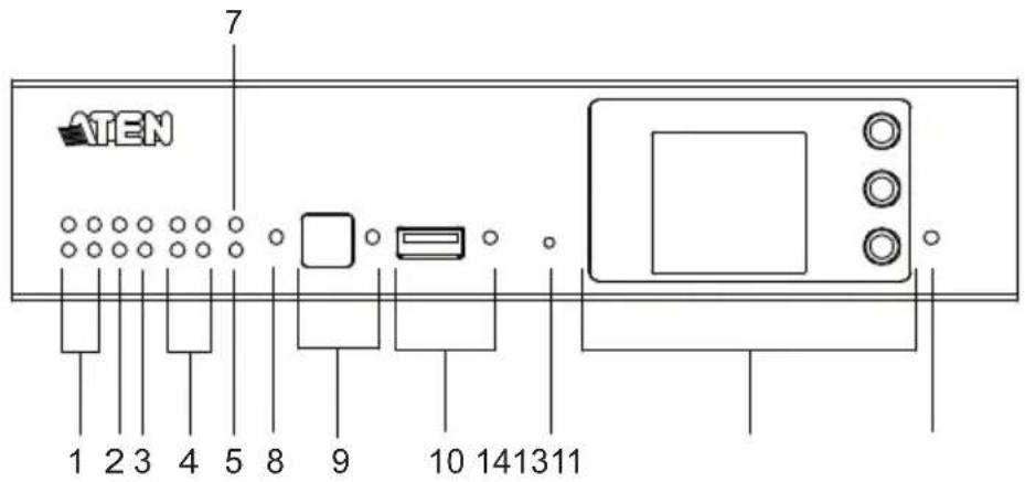
| No. | Component Description | tion | |||
| 1 relay LEDs | ♦Lights green to indicate an active device connection or signals being transmitted.♦Blinks green once to indicate system startup, with the buzzer beeping once | ||||
| 2 I/O LEDs | |||||
| 3 IR / serial LEDs | |||||
| 4 serial LEDs | |||||
| 5 | L | A | N | L | Lights green to indicate successful connection to the network. |
| 6 | S | y | s | t | Blinks green to indicate that the system is running without issues. |
| No. | Component Description | |
| 7 | Control LAN LED | Lights green to indicate successful connection to the network. |
| 8 | DC output overload LED | Lights orange to indicate DC output exceeding the maximum output threshold, with the buzzer beeping for 3 seconds.Note: Please unplug any of the connected devices to keep its total output under 12 V DC, 1 A / 2A and restart the unit. |
| 9 IR | receiver / LED Passes | es the functions of a remote control to the Control Box learning mode. The distance between the IR remote and the receiver window should be kept under 10 cm with a direct line of sight.The LED blinks green to indicate the unit is receiving signals from an IR remote controlThe LED lights green to indicate entering learning mode, or IR learning success with the buzzer beeping once. |
| 10 USB port / LED Plugs | in a USB device to upload Viewers (configured by the VK6000) to the Control Box.The LED blinks green to indicate that Viewers are being uploaded, and lights green to indicate a successful upload, with the buzzer beeping once upon USB plug-in and once upon upload success.The LED lights orange to indicate upload failure, with the buzzer beeping 3 times for no available file found or upload failure.Note: Control Box Gen. 2 is compatible with USB drivers in NTFS and FAT32 format. | |
| 11 reset button | Clear all settings but network and license: Press and hold until the front panel LEDs blink once, with the buzzer beeping once (about 8 seconds). The LEDs and buzzer will trigger once more when the reset is complete.Reset network settings: Short press once.Note: For more reset button functions, see page 359. | |
| 12 Control Box ID Switch | Use the switch to set an ID for the Control Box. | |
| 13 LCD panel and buttons | Use the Up, Down, and Enter buttons to display the unit's system information, and set its ID. | |
| 14 power LED Lights green when the unit is turned on. | ||
VK1100A Rear View
VK1200 Rear View

VK2100A Rear View

VK2200 Rear View

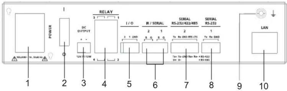
| No. | Component Description | |
| 1 | power socket Plugs in the power cord from an AC power source. | |
| 2 | power switch Powers the unit on or off. | |
| 3 12 | V DC output ports | 1 / 4 DC output port(s) providing a total output of 12 V DC, 1 / 2 A from the Control Box. |
| 4 | relay channels 4 / 8 channels; normally open, isolated relays with a contact rating of 24 V DC, 2 A max. | |
| 5 I/O | channels 2 / 4 / 8 channels that can be configured as digital inputs or outputs, with the first pin being ground and the rest being number pins.◆ Digital Input:◆ VDC Mode: 0 - 24 V DC; programmable range of 1 - 24 V DC◆ Dry Contact Mode: Pull-up 2k Ω to +12 V DC◆ Digital Output: 300 mA sink from 24 V DC | |
| 6 IR | / serial ports 2 / 4 / 8 IR ports that can also be configured as RS-232 TX ports. pin 1: Signal / pin 2: Ground. | |
| 7 RS | -232/422/485 serial ports | 1 / 2 5-pin RS-232/422/485 serial ports by pin assignment. |
| 8 RS | -232 serial ports | 1 / 4 / 6 3-pin RS-232 serial ports with Tx, Rx and GND. |
| 9 grounding terminal | Connects to the grounding wire. | |
| 10 LAN | ◆ Connects the unit to the corporate LAN for remote access and centralized management by ATEN Unizon.◆ Default network settings when no dynamic IP address is assigned by a DHCP server, after 30 seconds:VK2200 / VK1200◆ IP: 192.168.1.60◆ mask: 255.255.255.0VK2100A / VK1100A◆ IP: 192.168.0.60◆ mask: 255.255.255.0 | |
| 11 | Control LANConnects the unit to a secure subnetwork, separate from the corporate LAN, for managing IP devices and configuration by the ATEN Configurator VK6000, as well as for remote control by ATEN Keypads, Touch Panel or the ATEN Control System app on mobile devices.Default network settings when no dynamic IP address is assigned by a DHCP server, after 30 seconds:IP: 192.168.0.60mask: 255.255.255.0Supports DHCP server | |
Placement
Desktop
To place the control box on a flat surface, such as a desk, simply attach the foot pad set provided onto its 4 corners and place it on the surface.
Rack Mounting
■ VK2100A / VK2200
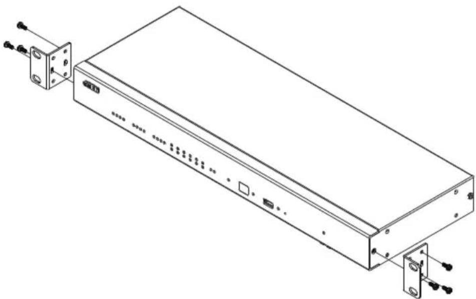
- The VK2100A / VK2200 can be mounted onto a 19" (1U) system rack. The following diagrams are exemplified using VK2100. Using the rack mount kit, attach the 2 mounting brackets onto the sides of the unit with the 6 screws included.
natural_image
Technical line drawing of a rectangular electronic device with ports and connectors (no text or symbols)- Align the mounting brackets' screw holes with that of the front of the rack, and use 4 self-supplied screws to secure the unit onto the rack.

natural_image
Isometric line drawing of a structural support frame with vertical supports and a central beam (no text or symbols)■ VK1100A / VK1200
Optionally purchase an ATEN Rack Mount Kit to install VK1100A / VK1200 onto a a 19" (1U) system rack. Users can select the 2X-049G or 2X-021G rack mount kit for single or dual rack mount, respectively.
Single Rack Mount (2X-049G)
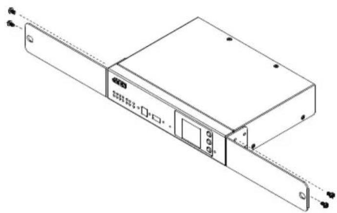
- Using the rack mount kit, attach the 2 mounting brackets onto the sides of the unit with the 4 screws (M3x6) included.
natural_image
Technical line drawing of a device chassis with mounting flanges and ports (no text or symbols)- Align the mounting brackets' screw holes with that of the front of the rack, and secure the unit onto the rack using 2 self-supplied screws.
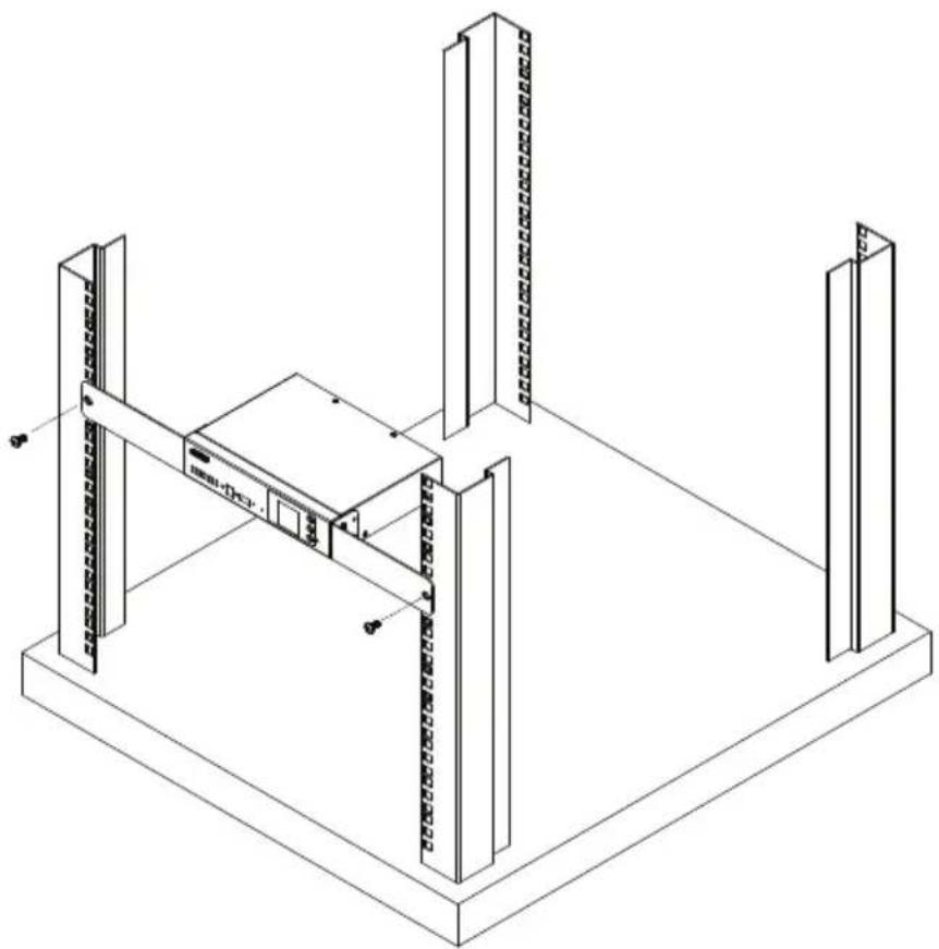
natural_image
Isometric line drawing of a server rack with vertical supports and mounting points (no text or symbols)Double Rack Mount (2X-021G)
- Remove 2 screws at the bottom and 1 screw at the side from each of the two VK1100A / VK1200 units, as shown below.

natural_image
Technical line drawing of two electronic device enclosures with mounting holes and control panels (no text or symbols)- Use 4 of the screws from step 2 to secure the two VK1100A / VK1200 units together with the link bracket. Then install the left and right mounting brackets onto the sides of the units using 2 of the M3x5 and M3x6 screws included.

natural_image
Technical line drawing of a device chassis with labeled components (no text or symbols present)- Align the mounting brackets' screw holes with that of the front of the rack, and secure the units onto the rack using 4 self-supplied screw.

natural_image
Isometric line drawing of a server rack with two vertical racks and a central rack unit (no text or symbols)■ VK1100
Optionally purchase an ATEN Rack Mount Kit (2X-031G) to install VK1100 onto a 19" (1U) system rack.
- Remove the 2 screws from the bottom and 1 screw from each side of the unit.

natural_image
Isometric line drawing of a rectangular electronic device with ports and connectors (no text or symbols)- Using the 2 bottom screws from step 1 and 2 M3x6 screws from the rack mount kit, secure the mounting brackets to the sides of the VK1100.
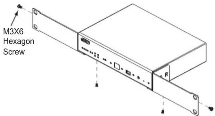
- Use 4 self-supplied screw to secure the mounting brackets onto the rack.

natural_image
Isometric line drawing of a structural frame assembly with vertical supports and a central support block (no text or symbols)Control Box Connections
To set up each device, refer to the installation diagrams on the pages that follows (each step provides a corresponding page with diagram), and do the following:
- Use a grounding wire to ground the unit by connecting one end to the grounding terminal and the other end to a suitable grounded object.
Note: Do not omit this step. Proper grounding helps prevent damage to the unit from surges or static electricity.
- Plug the power cord into the Control Box's power socket, and connect it to an AC power source.
- Use a Cat 5e/6 cable to connect the VK1100A / VK2100A's LAN (Ethernet) port or VK1200 / VK2200's Control LAN port to a secured subnetwork.
- (Optional) For VK1200 / VK2200, use another Cat 5e/6 cable to connect its LAN port to the corporate network.
- Use the DC output terminals to wire 12 V DC power connections using the instructions on page 30.
- Use the relay terminals to wire relay device connections using the instructions on page 32.
- Use the IR / serial (RS-232 TX) terminals to wire IR or serial device connections using the instructions on page 35.
- Use the digital I/O terminals to wire digital input / output device connections using the instructions on page 37.
- Use the 3-pin RS-232 terminals to wire RS-232 serial device connections using the instructions on page 39.
-
Use the 5-pin RS-232/422/485 terminals to wire the corresponding serial device connections using the instructions on page 41.
-
Connect IP-based devices to the same network as the Control Box. Refer to Ethernet / Control LAN, page 42 for details.
Note:
- For KNX-compliant devices, connect the devices to a KNX IP interface, and then connect the KNX IP interface to the network where the Control Box is installed.
-
To check if the KNX functions are supported by the Control Box, see Specifications, page 317.
-
Start the unit by switching on its power switch.
- For VK1200 / VK2200, use the LCD panel to set its ID.
VK1100A Installation Diagram

flowchart
graph TD
    A["Projector LiftCurtain Screen"] --> B["Relay"]
    C["Air Conditioning"] --> D["RS-232 / RS-422 / RS-485"]
    E["Lighting Control"] --> D
    F["Video Matrix Switch"] --> D
    G["Power Distribution Unit"] --> D
    H["Power Cord"] --> I["Power"]
    J["Terminal Block"] --> K["DI / DO"]
    L["Sensor"] --> M["IR / RS-232"]
    N["Door Sensor"] --> M
    O["Audio Mixer"] --> P["Ethernet"]
    Q["Conferencing"] --> P
    R["Rear View"] --> S["Ground"]
    T["6"] --> U["Relay"]
    V["10"] --> W["Relay"]
    X["9"] --> Y["Relay"]
    Z["1"] --> AA["Power"]
    AB["2"] --> AC["Power"]
    AD["5"] --> AE["Power"]
    AF["8"] --> AG["Power"]
    AH["7"] --> AI["Power"]
    AJ["3"] --> AK["Power"]
VK1200 Installation Diagram

flowchart
graph TD
    A["Power"] --> B["Power cord"]
    C["Terminal Block Sensor"] --> D["DI / DO Ethernet"]
    E["TV Blu-ray Player Amplifier Video"] --> F["IR / RS-232"]
    G["Audio MixerDoor SensorOccupancy Conferencing"] --> H["Ethernet"]
    I["Power Distribution Unit"] --> J["Relay"]
    K["Projector Lift Curtain Screen"] --> L["Relay"]
    M["Air Conditioning"] --> N["Relay"]
    O["Lighting Control Project"] --> P["Relay"]
    Q["Video Matrix Switch"] --> R["Relay"]
    S["Power"] --> T["Rear View"]
    U["RS-232 / RS-422 / RS-485"] --> V["Relay"]
    W["RS-232"] --> X["Relay"]
    Y["Power"] --> Z["Power"]
    AA["Power"] --> AB["Power"]
    AC["Power"] --> AD["Power"]
    AE["Power"] --> AF["Power"]
VK2100A Installation Diagram

flowchart
graph TD
    A["① Power cord"] --> B["② Tower Block"]
    B --> C["⑤ Sensor"]
    C --> D["⑧ Door Sensor"]
    D --> E["⑦ Party-ray Player Amplifier"]
    E --> F["⑧ Ethernet"]
    F --> G["③ Audio Mixer"]
    G --> H["④ Video Conferencing"]
    I["⑥ Projector Lift"] --> J["Relay"]
    K["⑩ Lighting Control Switch"] --> L["RS-232 / RS-422 / RS-485"]
    M["⑨ Power Distribution Unit"] --> N["RS-232"]
    O["⑪ Power Power"] --> P["DI / DO"]
    Q["⑪ DI / DO"] --> R["IR / RS-232"]
    S["⑪ IR / RS-232"] --> T["DI / DO"]
    U["⑪ IR / RS-232"] --> V["DI / DO"]
    W["⑪ IR / RS-232"] --> X["DI / DO"]
    Y["⑪ IR / RS-232"] --> Z["DI / DO"]
    style A fill:#f9f,stroke:#333
    style K fill:#f9f,stroke:#333
    style M fill:#f9f,stroke:#333
    style U fill:#f9f,stroke:#333
    style W fill:#f9f,stroke:#333
    style Y fill:#f9f,stroke:#333
VK2200 Installation Diagram

flowchart
graph TD
    A["Power Power"] --> B["Power cord"]
    A --> C["Terminal Block"]
    D["Relay"] --> E["Curtain"]
    D --> F["Lift"]
    D --> G["Projector Screen"]
    H["RS-232 / RS-422 / RS-485"] --> I["Air Conditioning"]
    H --> J["Lighting Video Matrix Switch"]
    K["RS-232"] --> L["Power Distribution Unit"]
    M["Ethernet"] --> N["ATEN UnizonProjector"]
    O["DI / DO"] --> P["Sensor"]
    O --> Q["Door Sensor"]
    O --> R["Oscution"]
    O --> S["Blu-ray Player"]
    T["IR / RS-232"] --> U["Amplifier"]
    V["Ethernet"] --> W["Audio Mixer"]
    V --> X["Video Conferencing"]
12 V DC Power Output
ATEN Control Box offers the following 12 V DC outputs for providing power to hardware devices:
| 12V DC Power Output VK1100A / VK1200 VK2100A / VK2200 | ||
| Number of Channels 1 | 4 | |
| Max. Power Supply DC | 12 V, 1 A DC 12 V, 2 A | |
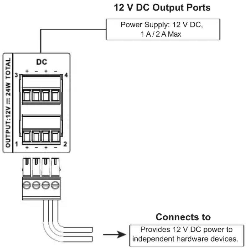
The outputs can power one or four independent hardware devices, one or four loops for connected relay devices, or one or four digital output devices.
If the combined current of the ports exceeds 1 A (VK1100A / VK1200) or 2 A (VK2100A / VK2200), the DC power overload LED lights orange, an alarm beeps three times, and the ports are turned off. To return power to the ports, power off the Control Box, unplug all hardware connected to the 12 V DC output ports, power on the Control Box, and then plug in the hardware devices, one at a time, and make sure the current does not exceed 1 A or 2 A.
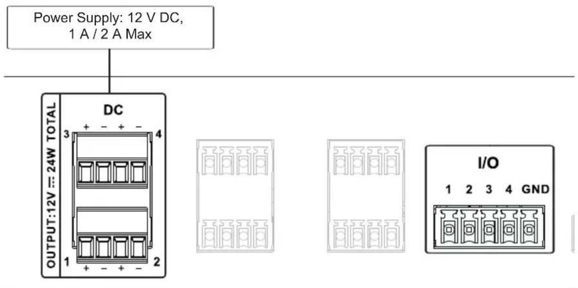
The diagrams on the next three pages show ports on the VK2100A / VK2200. The VK1100A / VK1200 is the same except that it has fewer 12 V DC terminal blocks.
Independent Power Supply
Digital Output Power Supply
12 V DC Output Ports

flowchart
graph TD
    A["Power Supply: 12 V DC, 1 A / 2 A Max"] --> B["DC"]
    B --> C["Output: 12V DC = 24W TOTAL"]
    B --> D["I/O"]
    B --> E["GND"]
    B --> F["Provides 12 V DC power for the digital output loop."]
    F --> G["Connects to Switch, Screen, Projector Lift, Lighting and Equipment Control."]
Digital Output Dual Power Supply (VK2100A/ VK2200 only)
12 V DC Output Ports

flowchart
graph TD
    A["1"] --> B["2"]
    B --> C["Provides connection to digital output #1."]
    C --> D["Provides connection to digital output #2."]
    D --> E["Provides 12 V DC power for the digital output loop."]
    E --> F["1"]
    E --> G["2"]
    F --> H["GND"]
Relay
ATEN Control Box provides the following isolated relays:
| Relay VK1100A / VK1200 / VK2100A VK2200 | ||
| Number of Channels 4 | 8 | |
| Contact Rating 24 V DC, 2 A | ||
| Default Status Normally Open | ||
Using Self-supplied Power

- All are normally open, isolated relays.
- Contact Rating: 24 V DC 2 A Max
Normally Open Closed
Connects to room control equipment
- For example, you may connect the relay channels to external relays, or devices equipped with relay channels, such as switch, screen, projector lift, lighting, motorized equipment, motion device, etc.
- Do no exceed a total of 24V DC, 2A for each channel.
Relay Power Supply

flowchart
graph TD
    A["12 V DC Output Ports"] --> B["DC"]
    A --> C["RELAY"]
    B --> D["INPUT: 24V = MAXIMUM"]
    C --> E["INPUT: 24V = MAXIMUM"]
    D --> F["Provides 12 V DC power for the relay loop."]
    E --> G["Connects to room control equipment"]
    H["Power Supply: 12 V DC, 1 A / 2 A Max"] --> A
    I["For example, you may connect the relay channels to external relays, or devices equipped with relay channels, such as switch, screen, projector lift, lighting, motorized equipment, motion device, etc."] --> G
    J["Do no exceed a total of 24V DC, 2A for each channel."] --> G
Application: Control Using External Relays
To install external relays, refer to the illustration below where two external relays are used to control a projector screen.
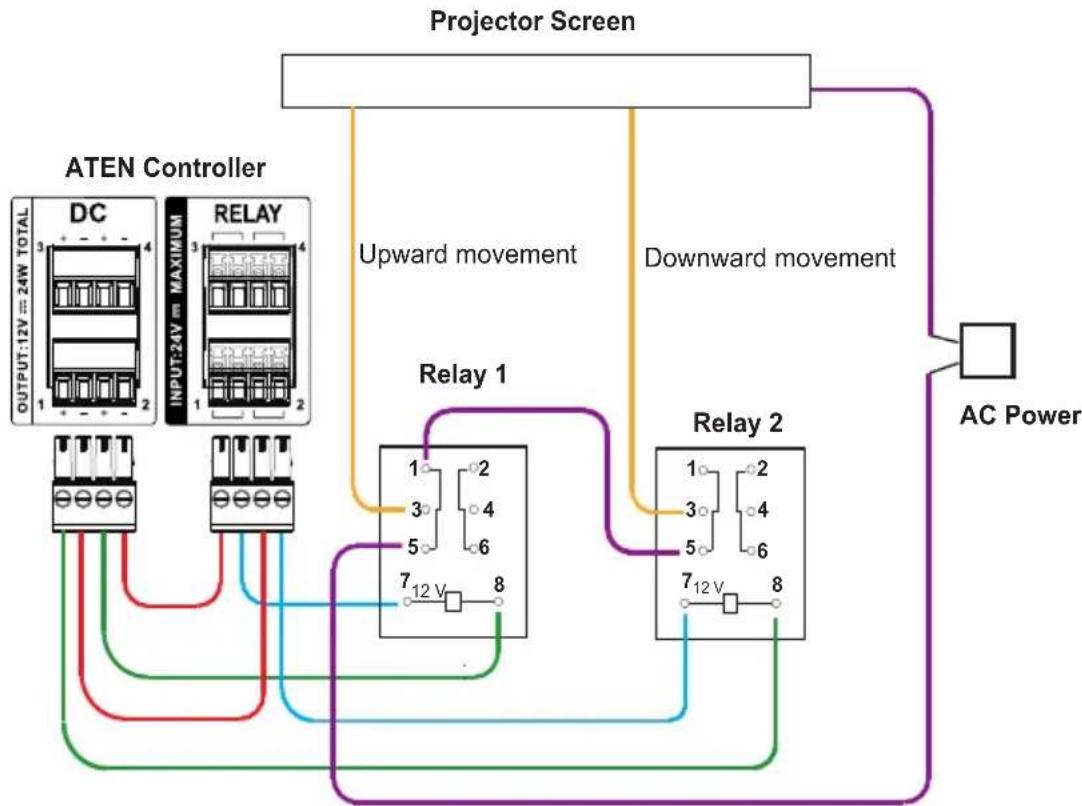
flowchart
graph TD
    A["ATEN Controller"] -->|DC/1 24W TOTAL| B["Projector Screen"]
    A -->|RELAY 1| C["Relay 1"]
    A -->|RELAY 2| D["Relay 2"]
    B -->|Upward movement| E["AC Power"]
    B -->|Downward movement| F["AC Power"]
    C --> G["7 12 V 8"]
    D --> H["7 12 V 8"]
    style A fill:#f9f,stroke:#333
    style B fill:#ccf,stroke:#333
    style C fill:#cfc,stroke:#333
    style D fill:#fcc,stroke:#333
    style E fill:#ffc,stroke:#333
    style F fill:#fcc,stroke:#333

IR / Serial
ATEN Control Box provides the following IR / serial (RS-232) ports:
| IR / Serial | VK1100AVK1200 | VK2100A VK2200 | ||
| 2-Pin IR/Serial 2 | 4 | 8 | ||
| IR | Carrier Frequency | 10 ~ 455 kHz | ||
| Default Level Low | ||||
| Serial (RS-232) | Baud rate | 300 ~ 115200 (default: 9600) | ||
| Data bit | 7, 8 (default) | |||
| Stop bit | 1 (default), 2 | |||
| Parity None (default), Even, Odd | ||||
| Signal Level TTL | (0 ~ 5 V DC) TTL (0 ~ 5 V DC) | |||
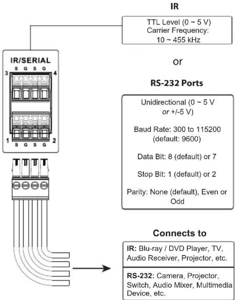
flowchart
graph TD
    A["IR/SERIAL 1 S G S G 2"] --> B["TTL Level (0 ~ 5 V)<br>Carrier Frequency: 10 ~ 455 kHz"]
    C["IR"] --> D["RS-232 Ports"]
    D --> E["Unidirectional (0 ~ 5 V<br>or +/-5 V)<br>Baud Rate: 300 to 115200<br>(default: 9600)<br>Data Bit: 8 (default) or 7<br>Stop Bit: 1 (default) or 2<br>Parity: None (default), Even or Odd"]
    F["Connects to"] --> G["IR: Blu-ray / DVD Player, TV,<br>Audio Receiver, Projector, etc."]
    F --> H["RS-232: Camera, Projector,<br>Switch, Audio Mixer, Multimedia<br>Device, etc."]
By default, the unidirectional IR / serial channels are set to transmit IR signals.
IR Connection: Connect a transmitter cable to a set of IR and ground terminals of the Control Box, and install the IR transmitter on or near the IR device's IR receiving port, as shown on page 36.
Serial Connection: Connect a serial device's receiver (RX) and ground terminals to a set of serial (TX) and ground terminals of the Control Box. Then configure the same serial port settings on both the Control Box and the connecting serial device, allowing them to communicate.
One IR Transmitter
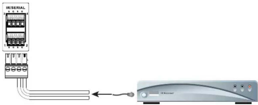
Two IR Transmitters
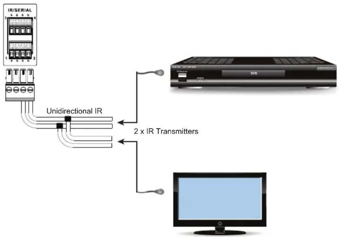
flowchart
graph TD
    A["IR/SERIAL"] -->|Unidirectional IR| B["TV Viewer"]
    B -->|2 x IR Transmitters| C["Computer"]
Digital I/O
The VK1100A / VK1200 / VK2100A / VK2200 provides the following digital input / output channels:
| Digital I/O | VK1100A / VK1200 | VK2100A | VK2200 | |
| Number of Channels 2 | 4 | 8 | ||
| Digital Input | VDC Mode | Voltage range: 0 ~ 24 V DCProgrammable range: 1 ~ 24 V DC | ||
| Dry Contact Mode | Pull-up: 2 kΩ to +12 V DC | |||
| Digital Output | Normally Open300 mA sink from 24 V DC | |||
Digital Input (Dry Contact):
Connects to digital I/O devices with an input loop — open or closed — for providing indicators from sensors or switches of an event, which can be used by the Control Box to trigger events and/or functions.
Digital Input (VDC Mode):
Connects to DC devices (temperature, current and monitor sensors) for providing voltage signals (1 to 24 V) to the ATEN Control Box, to trigger certain events and/or functions when the voltage signals are above or below the defined threshold.
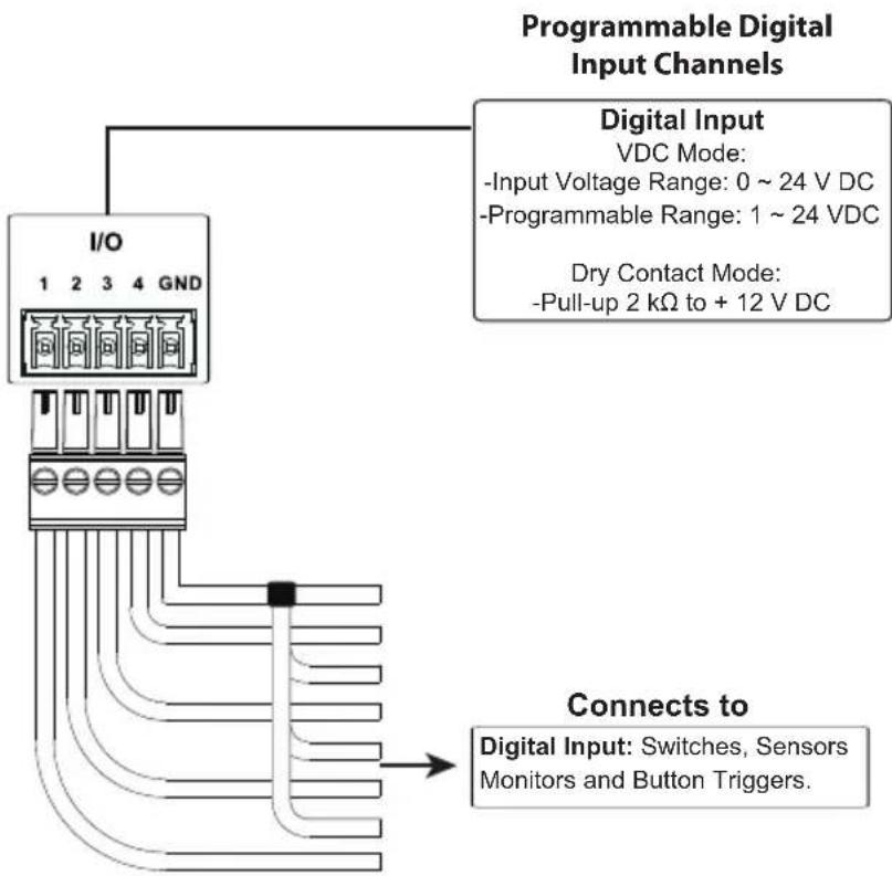
flowchart
graph TD
    A["Programmable Digital Input Channels"] --> B["I/O"]
    B --> C["Connects to: Digital Input: Switches, Sensors Monitors and Button Triggers."]
    B --> D["Digital Input: VDC Mode: -Input Voltage Range: 0 ~ 24 V DC, -Programmable Range: 1 ~ 24 VDC"]
    B --> E["Dry Contact Mode: -Pull-up 2 kΩ to + 12 V DC"]
Digital Output:
Provides non-powered dry contact (open and closed) circuit control of hardware devices, such as electric screens, projector lifts and other motorized equipment, which must be connected using a relay module, as shown below.

flowchart
graph TD
    A["Programmable Digital Output Channels"] --> B["I/O"]
    B --> C["1 2 3 4 GND"]
    B --> D["Digital Output: 300 mA sink from 24 V DC"]
    B --> E["Connects to: Digital Output: Switch, Screen, Projector Lift, Lighting and Equipment Control."]
    E --> F["Relay Module"]
RS-232 (3-Pin)
VK1200 / VK2100A / VK2200 provides the following 3-pin RS-232 ports:
| RS-232 (3-pin) VK1 | 100A / VK1200 VK2100 | A VK2200 | |
| Number of Channels 1 | 4 | 6 | |
| Baud rate 300 ~ 115200 (default: 9600) | |||
| Data bit 7, 8 (default) | |||
| Stop bit 1 (default), 2 | |||
| Parity None (default), Even, Odd | |||
Connect to devices for controlling and receiving status messages from them. For bidirectional RS-232 control, the transmit (TX), receive (RX) and ground (GND) terminals must be wired on both the ATEN Control System and the device connecting.

flowchart
graph TD
    A["SERIAL RS-232"] --> B["Bidirectional RS-232 Ports"]
    A --> C["Connects to"]
    A --> D["Baud Rate: 300 to 115200 (default: 9600)"]
    A --> E["Data Bit: 8 (default) or 7"]
    A --> F["Stop Bit: 1 (default) or 2"]
    A --> G["Parity: None (default), even or odd"]
    A --> H["Projector, Matrix Switch, Camera, etc."]
RS-232 / 422 / 485 (DB-9)
These two or four (VK1100 / VK2100) bidirectional ports provide serial control of hardware devices (projectors, switches, etc.) with programmable pin assignments and receive status messages from the connected devices. The diagram below shows ports on the VK2100. The VK1100 is the same except that it has fewer ports.

flowchart
graph TD
    A["SERIAL RS-232/422/485"] --> B["Programmable Bidirectional RS-232/422/485 Ports"]
    B --> C["Configurable by pin assignment"]
    C --> D["Baud Rate: 300 to 115200 (default: 9600)"]
    C --> E["Data Bit: 8 (default) or 7"]
    C --> F["Stop Bit: 1 (default) or 2"]
    C --> G["Parity: None (default), Even or Odd"]
    C --> H["Flow Control: None (default) or RTS/CTS"]
    A --> I["Connects to"]
    I --> J["Projector, Matrix Switch, Camera, etc."]
Pin Assignments
| RS-232 RS-422 RS-485 | ||
| pin 2: RX pin 1: | RX- pin 3: D+ | |
| pin 3: TX pin 2: | RX+ pin 4: D- | |
| pin 5: GND pin 3: | TX+ | pin 5: GND*Note:A ground terminal connection is recommended but not required. |
| pin 7: RTS pin 4: | TX- | |
| pin 8: CTS pin 5: | GND | |
RS-232 / 422 / 485 (5-Pin)
The ATEN Control System provides the following RS-232/422/485 ports:
| VK1100A / VK1200 VK2100A / VK2200 | ||
| Number of Channels 1 | 2 | |
| Baud rate 300 ~ 115200 (default: 9600) | ||
| Data bit 7, 8 (default) | ||
| Stop bit 1 (default), 2 | ||
| Parity None (default), Even, Odd | ||
Connect to devices, configurable by pin assignments, for controlling and receiving status messages from them.

Ethernet / Control LAN
The Ethernet / Control LAN port provides an Ethernet connection for controlling up to 25 (VK1100A / VK2100A) or 64 (VK1200 / VK2200) LAN devices and/or remote control by ATEN Keypads, Touch Panel, and the ATEN Control System app on a mobile device in a network.
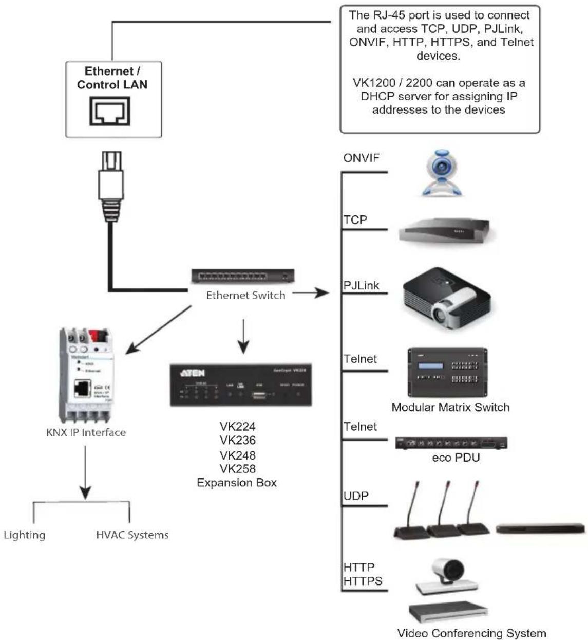
flowchart
graph TD
    A["Ethernet / Control LAN"] --> B["Ethernet Switch"]
    B --> C["ATEN"]
    C --> D["KNX IP Interface"]
    D --> E["Lighting"]
    D --> F["HVAC Systems"]
    G["The RJ-45 port is used to connect and access TCP, UDP, PJLink, ONVIF, HTTP, HTTPS, and Telnet devices. VK1200 / 2200 can operate as a DHCP server for assigning IP addresses to the devices"] --> H["ONVIF"]
    H --> I["TCP"]
    I --> J["PJLink"]
    J --> K["Telnet"]
    K --> L["Modular Matrix Switch"]
    L --> M["Telnet"]
    M --> N["eco PDU"]
    N --> O["UDP"]
    O --> P["HTTP HTTPS"]
    P --> Q["Video Conferencing System"]
Panel Components
VK0100

VK0200

| No. | Component Description | |
| 1 | buttons and button LEDs | Indicate the status of the Control Pad and if the function on each button, e.g. lighting or projector, is on or off. For detailed information about device/function status under different LED activities, seeLED Indications, page 45. |
| 2 | system LEDs Contains a | LAN and a link LED to indicate network connection and data transmission status:♦ LAN LED lights green to indicate that the Control Pad is connected to network.♦ Link LED lights green to indicate that the Control Pad is actively transmitting and receiving data. |
| 3 | reset button | ♦ To clear all the configurations except the network settings, press and hold the reset button for 8 seconds.♦ To reset the network settings, press the reset button once. |
| 4 | RS-232 serial ports Connect up to two RS-232 serial devices. | |
| 5 | relay channels Connect up to two relay devices. Relay contacts are normally open, isolated with a contact rating of 24 V DC, 1 A max. | |
| 6 | digital input Port Connect to one digital input device that supports programmable input (1 ~ 5 V DC) or dry contact (pull-up 2k ohms to 5 V DC). | |
| 7 | Ethernet port Connects to an Ethernet cable to provide power and access to the network. | |
| 8 | control pad ID switch Sets an ID for the Control Pad. | |
| 9 | DC power port Connects to a 5 V DC power adapter. | |
LED Indications
Refer to the table below for the status descriptions of a Control Pad indicated by button LEDs.
| Button LED Status | LED Activity Control | Pad Status |
| a button LED lights | orange The Control Pad | is powered on and the button is currently off. |
| a button LED lights | white The Control Pad | is powered on and the button is currently on. |
| a button LED blinks | orange and white repeatedly | The function assigned to the button is being executed. |
| all button LEDs blink | orange and white once | The Control Pad is restoring its default settings. |
| all button LEDs blink | orange and white repeatedly | The firmware of the Control Pad is being upgraded. |
Installing the Control Pads
- Prepare the installation site.
a) Choose a location where cables are free of interference. You can install the Control Pad on walls, desks, and podiums.
b) Prepare a recession on the chosen location to accommodate the Control Pad. You can install the Control Pad directly on the chosen location or through a wall box. For recommended cutout dimensions, see CAD and Panel Cutout Diagrams, page 340.
- Connect the Control Pad to various devices, for integration and control, refer to the corresponding interface for the wiring information of each:
♦ Wiring Information, page 51
♦ Relay Connections, page 52
♦ Digital Input Device, page 53
Note: To expand connection ports on the Control Pad, install ATEN Expansion Boxes.
- To use PoE, connect the Control Pad to a PoE switch via an Ethernet cable. For details, see Ethernet, page 54.
Note: If you do not have a power sourcing equipment for PoE, contact your local sales representative to purchase a power adapter and then follow the steps below to prepare the power cord.

(1) Cut the connector end of the power adapter.
(2) Strip 5 mm(0.5 cm) off the insulation cover of the power adapter cable to expose the +5V wire and the grounding wire.
(3) Insert the expose +5V wire and the grounding wire tightly into the provided 2-pin terminal block connector. Use a voltmeter to determine the polarity of an exposed wire.
VK0100
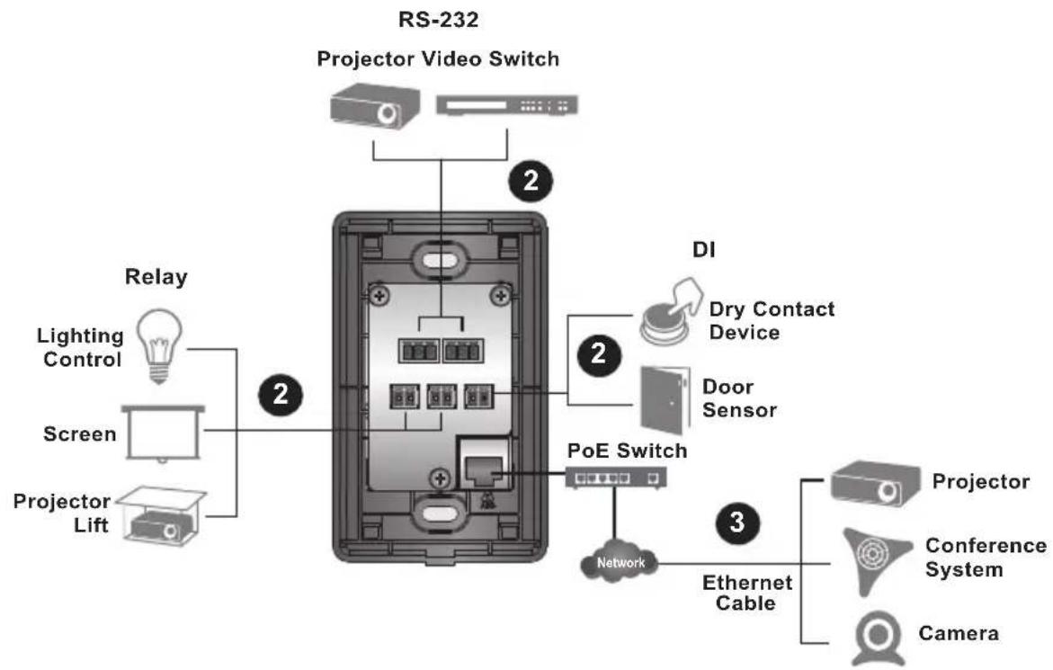
VK0200

flowchart
graph TD
    A["Projector Lift"] --> B["Screen"]
    B --> C["Lighting Control"]
    C --> D["Relay"]
    D --> E["Projector Video Switch"]
    E --> F["DI"]
    F --> G["Dry Contact Device"]
    F --> H["Door Sensor"]
    I["PoE Switch"] --> J["Network"]
    K["Ethernet Cable"] --> L["Conference System"]
    M["Camera"] --> N["Projector"]
    style A fill:#f9f,stroke:#333
    style B fill:#ccf,stroke:#333
    style C fill:#cfc,stroke:#333
    style D fill:#fcc,stroke:#333
    style E fill:#cff,stroke:#333
    style F fill:#ffc,stroke:#333
    style G fill:#fcf,stroke:#333
    style H fill:#ccf,stroke:#333
    style I fill:#cfc,stroke:#333
    style J fill:#fcc,stroke:#333
    style K fill:#cfc,stroke:#333
    style L fill:#fcc,stroke:#333
    style M fill:#cfc,stroke:#333
- Use the ID Switch to assign an ID to the Control Pad.
Note: It is possible to install more than 16 controllers under the same subnet. In which case, the 17th controller and the ones added after that will each be sharing its ID with another controller. If you have any ATEN Expansion Box and/or Keypad connected to controllers using shared IDs, reconfigure the connection mode. For details, see Controller Properties, page 116.
- Power on all the devices. The button LEDs light orange.
- Assemble the button caps onto the Control Pad.
a) Assemble button caps of the same row with each other. Put the button with two latches to the far right.
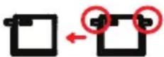
b) From the top row, attach each row of button caps to the Control Pad by pressing on the latches.
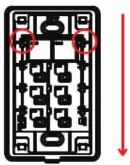
Caution: When removing button caps, place your fingers on the top of button caps and then press downwards, as illustrated below. Pressing upwards from the bottom may cause damages to the button caps.

natural_image
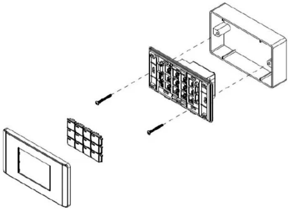
Diagram of a rectangular electrical or mechanical component with internal grid structure and red arrows indicating direction (no text or symbols)- Mount the Control Pad to the chosen location with or without a wall box.
a) Secure the Control Pad to the chosen location with self-prepared screws.
b) Install the supplied faceplate to the Control Pad.
VK0100

natural_image
Exploded view diagram of a device showing internal components and assembly (no text or labels)VK0200 (for EU type)

natural_image
Diagram of a device assembly showing components from a front panel to an internal box, with no visible text or symbols.VK0200 (for MK type)
Wiring Information
RS-232 Serial Connection
The two bidirectional RS-232 ports on the Control Pad provide serial control of hardware devices (projectors, matrix switches, etc.) and receive status messages from the connected devices. For bidirectional RS-232 control, the transmit, receive, and ground pins must be wired on both the Control Pad and hardware device. Each hardware device requires different wiring. Please consult each hardware device's manual for details.

flowchart
graph TD
    A["Bidirectional RS-232 Ports"] --> B["Baud Rate: 300 to 115200 (default: 9600)"]
    A --> C["Data Bit: 8 (default) or 7"]
    A --> D["Stop Bit: 1 (default) or 2"]
    A --> E["Parity: None (default), even or odd"]
    A --> F["Serial RS-232"]
    F --> G["1 TX RX GND"]
    F --> H["2 TX RX GND"]
    F --> I["3/4/5/6/7/8/9/10/11/12/13/14/15/16/17/18/19/20/21/22/23/24/25/26/27/28/29/30/31/32/33/34/35/36/37/38/39/40/41/42/43/44/45/46/47/48/49/50/51/52/53/54/55/56/57/58/59/60/61/62/63/64/65/66/67/68/69/70/71/72/73/74/75/76/77/78/79/80/81/82/83/84/85/86/87/88/89/90/91/92/93/94/95/96/97/98/99"]
    F --> G
    G --> H
    H --> I
    I --> J["Connects to Projector, Matrix Switch, Camera, etc."]
Relay Connections
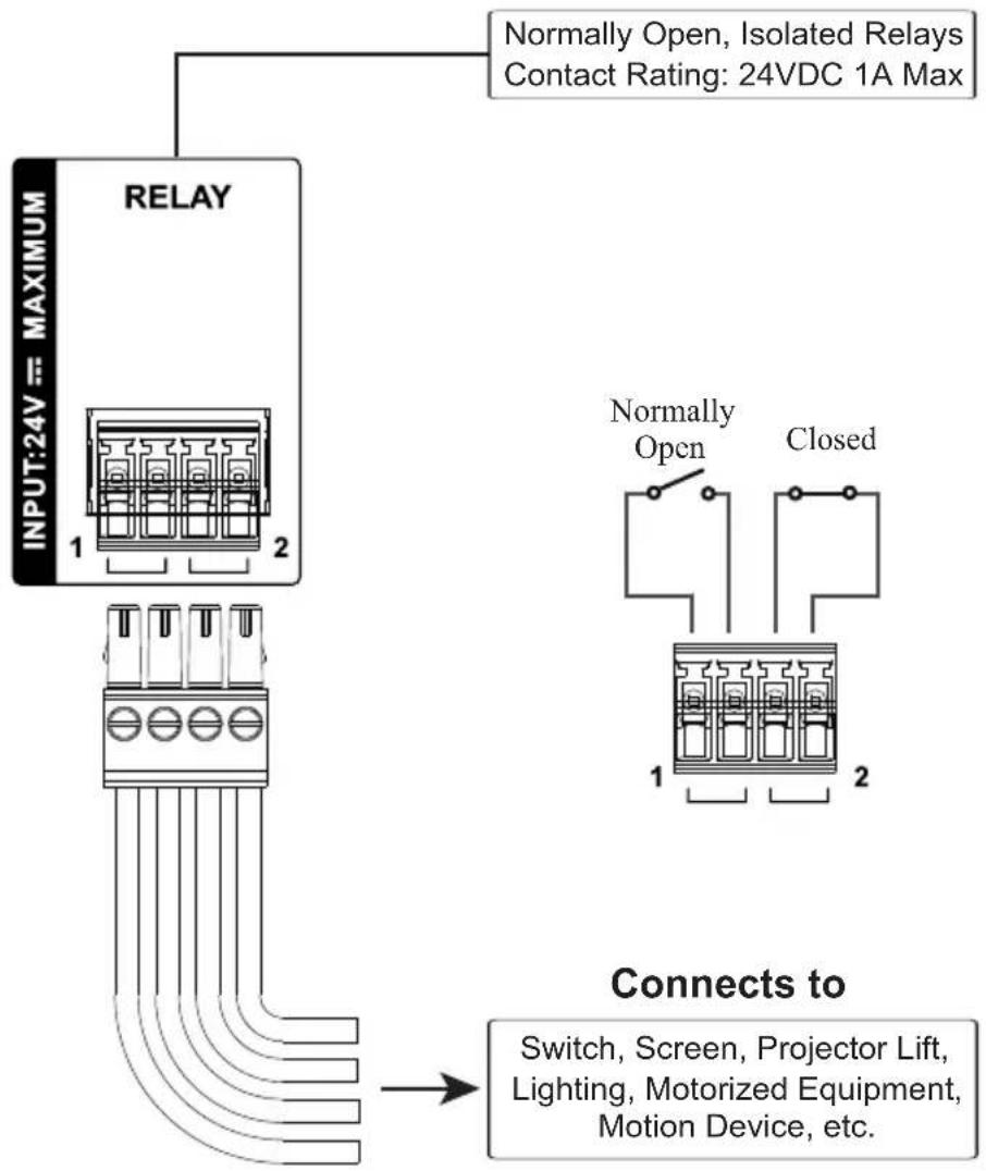
These 2 relay channels provide connections to control hardware devices such as electric screens, projector lifts and other motorized equipment. Each relay is normally open by default.
2 x Relay Channels
Digital Input Device
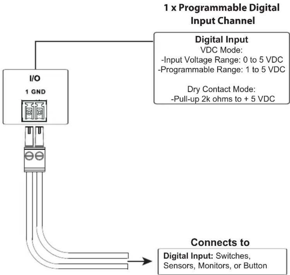
The digital input port on the Control Pad can be used to install a digital input device such as a switch or a sensor. The digital input channel can be configured to the VDC mode or the Dry Contact mode.
flowchart
graph TD
    A["I/O 1 GND"] --> B["Connects to Digital Input: Switches, Sensors, Monitors, or Button"]
    C["Digital Input VDC Mode: -Input Voltage Range: 0 to 5 VDC\n-Programmable Range: 1 to 5 VDC"] --> D["Connects to Digital Input: Switches, Sensors, Monitors, or Button"]
    style A fill:#f9f,stroke:#333
    style C fill:#ccf,stroke:#333
Digital Input (Dry Contact):
Digital inputs are hardware devices (switches, sensors, monitors) with two circuit signals – open and closed. These two signals provide indicators from sensors or switches of an event. An event can be the on/off power, dry contact, sensor or switch status from a device. This information is used to trigger events and functions through the Control Pad.
Digital Input (VDC):
Digital input 5VDC hardware devices (temperature, current and monitor sensors) provide voltage signals between 1 and 5. A digital input port detects if a voltage is above/below a specific threshold (1 to 5). If the voltage coming from a hardware device is higher than the set value, the Control Pad will detect the digital input as high. If the voltage coming from a hardware device is lower than the set value, the Control Pad will detect the digital input as low. This information is used to trigger events and functions through the Control Pad.
Ethernet
The RJ-45 port provides an Ethernet connection for accessing the web console (page 79), controlling up to 8 IP devices, and remote control by the Control System app within the same subnetwork.

flowchart
graph TD
    A["Ethernet"] --> B["Ethernet Switch"]
    B --> C["KNX IP Interface"]
    C --> D["Lighting"]
    C --> E["HVAC Systems"]
    F["The RJ-45 port is used to connect and access TCP, UDP, PJLink, ONVIF, HTTP, HTTPS, and Telnet devices."] --> G["ONVIF"]
    G --> H["TCP"]
    G --> I["PJLink"]
    G --> J["Telnet"]
    G --> K["Modular Matrix Switch"]
    G --> L["Telnet"]
    L --> M["eco PDU"]
    L --> N["UDP"]
    L --> O["HTTP HTTPS"]
    L --> P["Video Conferencing System"]
    B --> Q["ATEN"]
    Q --> R["Expansion Box"]
ATEN Expansion Box
ATEN Expansion Boxes (sold separately) provide additional ports for a flexible expansion of the ATEN Control System. This allows you to add and control additional devices in an environment when more devices are required. With the advantage of an Ethernet-based connection, the expansion boxes are easily connected to the ATEN controller via a LAN connection from a variety of locations across a network. The diagram below provides a setup example using the VK224, a 4-Port Serial Expansion Box.
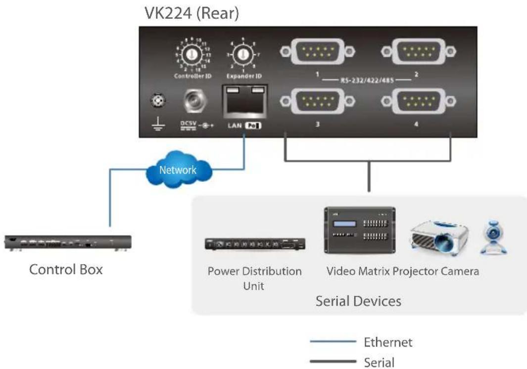
flowchart
graph TD
    A["Control Box"] --> B["VK224 (Rear)"]
    B --> C["Controller ID"]
    B --> D["Expander ID"]
    B --> E["RS-232/422/485"]
    B --> F["LAN"]
    B --> G["3"]
    B --> H["4"]
    B --> I["Network"]
    I --> J["Power Distribution Unit"]
    I --> K["Video Matrix Projector Camera"]
    I --> L["Serial Devices"]
    style A fill:#f9f,stroke:#333
    style B fill:#ccf,stroke:#333
    style C fill:#cfc,stroke:#333
    style D fill:#fcc,stroke:#333
    style E fill:#cff,stroke:#333
    style F fill:#ffc,stroke:#333
    style G fill:#cfc,stroke:#333
    style H fill:#fcc,stroke:#333
    style I fill:#fff,stroke:#333
    style J fill:#fff,stroke:#333
    style K fill:#fff,stroke:#333
    style L fill:#fff,stroke:#333
Note:
- To add and configure ATEN Expansion Boxes, see Left Sidebar, page 110 and Expansion Box (Expander), page 117.
◆ The available Expansion Box models include:
| Model Description |
| VK224 4-Port Serial Expansion |
| VK236 6-Port IR/Serial Expansion Box |
| VK248 8-Channel Relay Expansion Box |
| VK258 8-Channel Digital I/O Expansion Box |
Control Interface Devices
ATEN Keypad
The ATEN Keypad mounts to a wall to provide control of hardware through a controller. The setup of the Keypad to the Control System can be illustrated as follows:
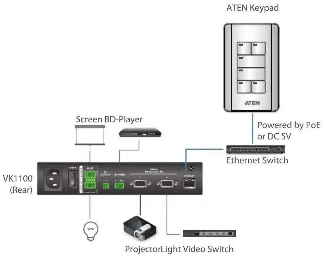
Note:
◆ The following Keypad models are available:
| Model Description | |
| VK108US 8-Button Keypad (US, 1 Gang) | |
| VK112EU 12-Button Keypad (EU, 2 Gang) |
- To have your Keypad buttons customized with text engraving, visit this page to make your order:
https://www.aten.com/ext_data/global_en/VK_Keypad_Engraving_Service/aten_keypad.html
Hardware Overview VK108US

VK112EU

No. Component Description
| 1 buttons VK108US | The Keypad can be customized up to 14 different layouts using 4 to 8 buttons. | |
| VK112EUThe Keypad can be customized up to 12 different layouts using 6 to 12 buttons. | ||
| 2 button LEDs Indicate function and Keypad statuses. For detailed information, seeLED Indications, page 59. | ||
| 3 | s y s t e indicators | m LAN: lights green to indicate that the Keypad is connected to LAN.Link: lights green to indicate that the Keypad is connected to the assigned controller. |
| 4 reset pushbutton Press to reset the Keypad to its default network settings. | ||
| 5 DC power Plug a power adapter into this DC power input. | ||
| 6 keypad ID switch Sets an ID to the Keypad (1~8). | ||
| No. | Component Description | ||
| 7 | controller ID switch | Sets the ID of the controller (1 ~ 16) to which the Keypad connects. | |
| 8 | L A N p | ◆ Connects the Keypad to LAN◆ Supplies power (PoE) if a power sourcing equipment is installed. | |
LED Indications
Refer to the table below for the status descriptions of a Keypad indicated by button LEDs.
| Keypad Button LED Activity Keypad Status | ||
| a button LED lights or | orange The Keypad is p | powered on and the button is currently off. |
| lights white The Keypad | ad is powered on and the button is currently on. | |
| blinks orange and white repeatedly | The function assigned to the button is being executed. | |
| all button LEDs | blink orange and white repeatedly | The firmware of the Control Pad is being upgraded. |
| blink orange The Keypad is disconnected from the Control Box. | ||
Layout Examples
VK108US
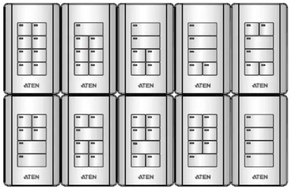
VK112EU
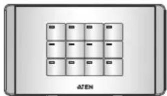
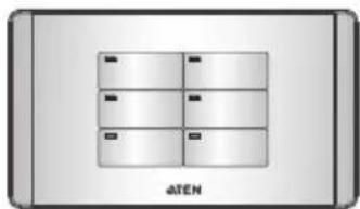
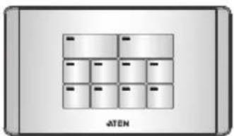
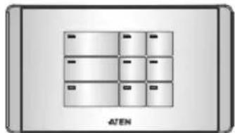

natural_image
Diagram of a 3x4 grid layout with labeled boxes and 'ATEN' text at bottom (no other symbols or text)
natural_image
Exterior view of a modern office building (no signage)
natural_image
Exterior view of a modern office building (no signage)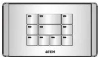
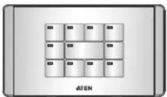
natural_image
Diagram of a grid layout with control buttons, no text or symbols present
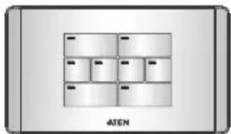

natural_image
Diagram of a device layout with six rectangular compartments and labeled 'ATEN' at the bottom (no readable text or symbols within the diagram itself)Installing ATEN Keypad
- Prepare the installation site.
a) Choose a location where cables are free of interference. You can install the keypad on walls, desks, and podiums.
b) Prepare a recession on the chosen location to accommodate the keypad. You can install the keypad directly on the chosen location or through a wall box. For recommended cutout dimensions, see CAD and Panel Cutout Diagrams, page 340.
- Use the keypad ID switch to set an ID for the unit, and set the controller ID switch to the ID of the controller to which you wish to connect.
Note: One ATEN Control Box/ Control Pad can work with up to 8 Keypads.
- Supply power and network connectivity to the keypad. Do one of the following:
◆ Use an Ethernet cable to connect the keypad to a PoE switch.
If you do not have a power sourcing equipment, use an Ethernet cable to connect the keypad to LAN and a power adapter to supply power. Follow the steps below to install a terminal block to the power adapter.

(1) Cut the connector end of the power adapter.
(2) Strip 5 mm(0.5 cm) off the insulation cover of the power adapter cable to expose the +5V wire and the grounding wire.
(3) Insert the expose +5V wire and the grounding wire tightly into the provided 2-pin terminal block connector. Use a voltmeter to determine the polarity of an exposed wire.
The LAN LED light green to indicate that the Keypad is supplied with power and successfully linked to the network.
Note:
- Make sure to install the Keypad to the same subnet with its assigned controller.
-
The Keypad adopts the default IP address 192.168.0.60 if the network switch does not support DHCP. To configure the IP address, log in the web interface using the default IP address and the default password (password).
-
Secure the Keypad to the chosen surface and install the button caps and faceplate.
a) Secure the Keypad to the chosen surface using two screws.
VK108US

natural_image
Exploded view diagram of a battery pack assembly showing internal components and pin connections (no text or labels)VK112EU

natural_image
Diagram of a device assembly showing components from a front panel to an internal grid, with no visible text or symbols.VK112MK

b) Follow the layout created in the Viewer and assemble the button caps onto the Keypad.
- Assemble button caps of the same row with each other. Put the button with two latches to the far right.

- From the top row, attach each row of button caps to the Keypad by pressing on the latches.
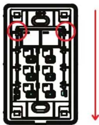
Caution: When removing button caps, place your fingers on the top of button caps and then press downwards, as illustrated below. Pressing upwards from the bottom may cause damages to the button caps.

natural_image
Pure electrical circuit lines without any symbols- Attach the faceplate to the Keypad.
IMPORTANT: After installing the Keypad, create a control interface (Viewer) and upload the Viewer to the controller. For details, see Design, page 100.
ATEN 8" Touch Panel (VK320)
Hardware Overview

| No. | Component Description |
| 1 | microphones Receive audio input. |
| 2 | restart button Pin this button to restart the device. |
| 3 | set button Pin this button to open the system settings page. |
| 4 | USB-C slot Receives a USB-C cable for firmware upgrades and app updates. |
| 5 | LED light bars Lights up when the touch panel is receiving power. |
| 6 | speakers Play beep sounds to indicate control actions. |
| 7 | plate screw Holds the touch panel to the wall plate. |
| 8 | power port Receives a power jack. |
| 9 | Ethernet port Receives an Ethernet cable which supplies network connectivity. It can also receive power if connected to a power sender (PSE), such as a PoE switch. |
Mounting the VK320 Touch Panel
Wall Mount
- (Optional) To use a junction box, cut out a space in the chosen surface to accommodate the junction box.
- Loosen the plate screw and remove the wall plate from the touch panel.
- Connect the device to power through PoE or DC power.
PoE
(a) Connect the supplied 90irc RJ-45 cable adapter to an Ethernet cable (that is connected to a PoE switch), and then thread the other end of the cable through the junction box and the wall plate.
Important: Install the wall plate with the screw hole facing outward. For a portrait view of the touch panel, keep the screw hole at the bottom (as illustrated); for a landscape view, install the plate with the screw hole on the right.
(b) Secure the wall plate to the junction box using the supplied screws.
(c) Plug the other end of the cable adapter to the PoE port of the touch panel.
- Terminal block
Follow the steps in Preparing the Power Cord to install the terminal block.
(a) Connect the power adapter to a power source, and then thread the other end of the cable through the junction box and the wall plate.
Important: Install the wall plate with the screw hole facing outward. For a portrait view of the touch panel, keep the screw hole at the bottom (as illustrated); for a landscape view, install the plate with the screw hole on the right.
(b) Secure the wall plate to the junction box using the supplied screws.
(c) Plug the terminal block to the power port of the touch panel.
- Slide the touch panel onto the wall plate until it is locked in position, and then secure the touch panel with the screw that you removed at step 2. The LED light bars light green to indicate that the panel is receiving power.
Tabletop Mount using the VK102 Tabletop Kit
Optionally purchase a tabletop kit (VK102) for using the touch panel on a desktop. For a step-by-step install procedure, visit the VK102 product page and download VK102 Tabletop Kit Quick Start Guide.
Configuring Network Settings
- Pin the set button once. The Settings page appears.
- Tap Network & Internet.
- Tap the listed settings to configure them as needed.
Changing the Interface Language
- Pin the set button once. The Settings page appears.
- Tap System > Languages & input.
Updating Control System App
To update the Control System app on your touch panel, follow the steps below.
Note: The Control System app can only be updated to a newer version.
- Download the Control System app of your chosen version from the product page and save the file to a type-C USB flash drive.
- Insert the USB flash drive to the USB Type-C port.
-
From the main page, tap . The system settings page appears.
-
Tap Storage > USB drive.
-
Locate and tap the app installer that downloaded. A confirmation message appears.
-
Tap Continue, and then Install to start the update. When the update is complete, a message appears.
Upgrading Firmware for ATEN Touch Panel
To upgrade the firmware of the touch panel to a newer version, follow the steps below.
Note: The firmware of the VK320 touch panel can only be upgraded to a newer version.
- Download the firmware package from the VK320 product page.
- Unzip the downloaded firmware package and save the file to the root directory of a USB flash drive (in FAT32), e.g. E:\
- Insert the USB drive to the USB Type-C port of the touch panel. The touch panel automatically saves a copy of the firmware file to its system. When the copy is complete, a “transfer completed” message appears.
- Pin the Set button on the unit, and then tap System > Advanced > System updates. The upgrade starts. When the firmware upgrade is complete, the touch panel reboots itself.
- A message appears to prompt you to remove the firmware file from the touch panel. Tap Yes to complete the upgrade.
Note: Make sure to remove the firmware file to prevent another upgrade.
Other Configurations & Actions
◆ To access the settings page, pin the set button once.
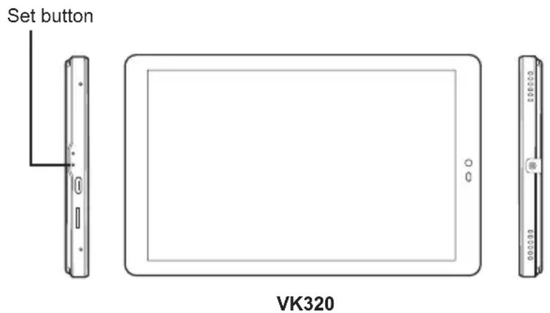
- To restart the device, pin the restart button once.
ATEN 10" Touch Panel (VK330)
Hardware Overview
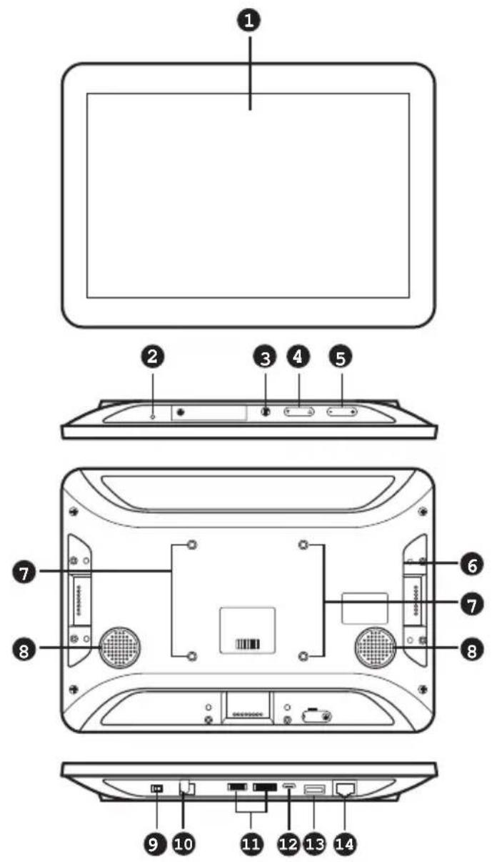
| No. | Component Description |
| 1 | touch screen Tap on the screen to operate the control system and/or configure the touch panel. |
| 2 | status LED Lights on when the touch panel is powered on. |
| 3 | function button Press the Function button to show the settings page. |
| 4 | brightness up / down Press to adjust the display brightness. |
| 5 | volume up / down Press to adjust the volume of the touch panel. |
| 6 | stereo audio out Connects to a stereo audio output. |
| No. | Component Description | |
| 7 | screw holes for panel plate | Screw holes used to secure a panel plate to mount the touch panel on a wall. |
| 8 | speakers Plays beep sounds to indicate control actions. | |
| 9 | contact pins Connect to an Access Inspector (VK401) to receive and transmit data. | |
| 10 | power switch Turns the touch panel on or off. | |
| 11 | power jack Receives a power cord. | |
| 12 | reserved for debugging purpose | These ports are reserved for debugging. |
| 13 | USB Micro-B port Use this port to upgrade/downgrade the device firmware. | |
| 14 | USB type-A port Use this port to update the ATEN Control System app installed in the Touch Panel. For details, see Updating Control System App, page 73. | |
| 15 | LAN port with PoE Receives an Ethernet cable which supplies network connectivity. It can also receive power if connected to a power sender (PSE), such as a PoE switch. | |
Mounting the Touch Panel
The VK330 Touch Panel supports desk mount, wall mount, or any 3rd-party mounting accessory that is VESA compliant (75 x 75 mm). For more information about the mounting accessories, please visit the product web page.
Desk Mount
To mount the VK330 on a desk using ATEN desk mount accessory — VK304 — refer to the diagram below.

natural_image
Technical line drawing of a mechanical device with projection lines and a screen (no text or symbols)Wall Mount
To mount the VK330 onto a wall using ATEN wall mount accessory — VK302 — follow the steps and refer to the diagrams below.
-
Using the wall anchors and screws, secure the wall plate to the wall in the illustrated direction. Secure the panel plate to the VK330 using the M4 screws.
-
Slide the panel plate to the wall plate to secure the VK330 onto the wall.

Installing the Touch Panel
-
Using the 90° RJ-45 cable adapter (if provided for your package edition) and an Ethernet cable, connect the unit to a PoE switch or PoE injector to provide power and access to the network.
-
Put the power switch to ON. The status LED lights green and the Touch Panel starts loading and displays the Start page.
flowchart
graph TD
    A["Start"] --> B["SYSTEM"]
    B --> C["FOR"]
    C --> D["ATEN"]
    D --> E["DEMO"]
    style A fill:#000,stroke:#000,color:#fff
    style B fill:#000,stroke:#000,color:#fff
    style C fill:#000,stroke:#000,color:#fff
    style D fill:#000,stroke:#000,color:#fff
    style E fill:#000,stroke:#000,color:#fff
    note right of A: Control Without Complication
Operating the Touch Panel
Note: In highly humid environment, it is advised that you keep the touch panel powered on and in operation to prevent fogging inside the touch panel.
- To configure system settings of the Touch Panel, press the Function button on the device open the system settings page.
- To return to the ATEN Control System app from the settings page, tap Return to ATEN Control System App.
- For details on using the Control System app, see Demo/Start Screen, page 290.
Changing the Interface Language
- Press the Function button.
- Tap System > Languages & input > Languages > + Add a language.
- Tap a preferred language. The selected option is added to the language list.
- Tap and hold the language you just added to the top of the list. The Touch Panel uses the language that lists first.
Configuring the Network Settings
- Press the Function button.
- Tap Network & Internet > Ethernet > Ethernet IP Mode to configure the settings.
Updating Control System App
To update the Control System app on your ATEN Touch Panel, follow the steps below.
- Download the Control System app from the product web page and save the file to a USB drive.
- Insert the USB drive to the USB Type-A port.
- Press the Function button to go to the system settings page.
- Tap Storage. Under Portable Storage, tap the USB device you inserted.
- Locate and tap the app file (.apk) to start the update.
Upgrading Firmware for ATEN Touch Panel
To upgrade the firmware on your ATEN Touch Panel, follow the steps below.
- Download the ATEN Touch Panel firmware package from the product page.
- Unzip the downloaded firmware package.
- In the update folder, locate the update.zip file and save it to the root directory of a type-C USB flash drive, e.g. E:\

- Insert the USB flash drive to the USB Type-A port of the Touch Panel.
- Press the Function button to go to the system settings page.
- Tap System > System updates.
- Follow the on-screen instructions to upgrade the firmware.
- The touch panel reboots itself when the firmware upgrade is complete.
Note: The Control System App installed on the touch panel may not be of the same version after this upgrade. Update the app to obtain the latest features and benefits.
Accessories
VK401 Access Inspector
Components


natural_image
Simple line drawing of a battery with a top terminal and two side outlets (no text or symbols)| No. | Component Description |
| 1 | contact pins The contact pins transmit detected data to a VK330 Touch Panel. |
| 2 | detection area Detects access cards. |
| 3 | screw holes Use these screw holes and the provided screws to secure an Access Inspector to a VK330 Touch Panel. |
Installing an Access Inspector to a VK330 Touch Panel
Make sure that you power off the VK330 Touch Panel and disconnect it from the power source before installing the Access Inspector.
Note: This application requires centralized management of the control system and Room Booking System (with at least one RBS panel) via ATEN Unizon. For more information, see ATEN Unizon User Manual and ATEN Room Booking System User Manual.
- Attach the VK401 Access Inspector to the VK330 Touch Panel with the VK401's contact pins facing the contact pins of VK330 Touch Panel.

- Fasten the VK401 to the VK330 using the 2 supplied screws.

natural_image
Top-down schematic of a device casing with buttons and display panel (no text or symbols)- Connect the VK330 to the power source and then switch its power switch to turn it on.
Chapter 3
Web-based Configuration and
Control
Overview
The ATEN controller can be configured over a standard TCP/IP connection via its built-in Graphical User Interface (GUI). Because it can be accessed from anywhere over a network or the Internet, operators can easily log in via a web browser. The web interface can be used to upload licenses, set the access key, enable monitors and upgrade the firmware.
Determining the IP Address of the Controller
- DHCP: When connected to a DHCP network, the ATEN controller is automatically assigned with an IP address upon startup. To determine the IP address of VK1200 / VK2200, see LCD Panel. To determine the IP address of other ATEN controllers, see IP Installer.
- Non-DHCP: When no dynamic IP address is assigned to the ATEN controllers within 30 seconds after startup, their default network settings are applied, as described below:
| Models Default IP Address | |
| VK1200 / VK2200 | Control LAN 192.168.0.60 |
| LAN 192.168.1.60 | |
| Other ATEN controllers 192.168.0.60 | |
LCD Panel
For VK1200 / VK2200, users can find its network information on the LCD panel, via Information, as illustrated below.
![UK2200 Control Box ID [01] > IP CLAN 192.168.0.60 LAN 10.0.1.100 > NEXT << BACK TO MENU](/content/2026/05/1091984/images/2d63e120a4103e6f151a5cdd45d8a0f520ecbfa9bac4d780b91646357f81d563.jpg)
IP Installer
Using a Windows PC, download the IP Installer zip file in Support and Downloads from the ATEN controller's product web page. Then extract and execute IPInstaller.exe. A window similar to the one below appears.

Make sure the proper network adapter is selected and click Enumerate to search for and display your ATEN controllers within the Device List.
Login
To access the GUI, type the IP address of the controller into the address bar of any browser. If a Security Alert dialog box appears, accept the certificate — it can be trusted. The Welcome screen appears:

◆ The default access key is: password
- Allows up to 8 concurrent logins
◆ Supports Internet Explorer 11
Dashboard
Overview
The Dashboard appears when you successfully log in to the controller. The Dashboard gives a quick view of the current settings and provides a link (Edit button) to each configuration page.
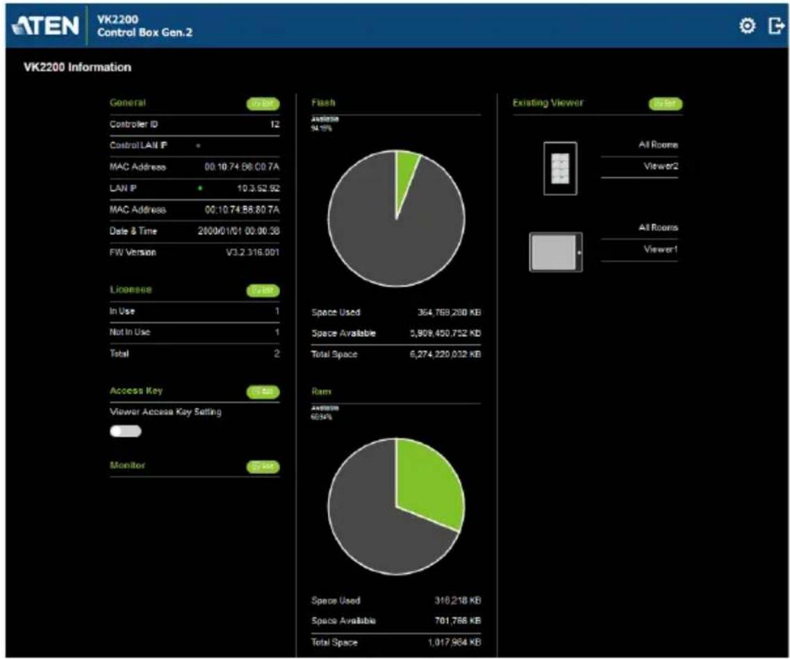
pie
VK2200 Information | Category | Value | |---|---| | Flash | 94.15% | | Space Used | 364,768,280 KB | | Space Available | 5,909,450,752 KB | | Total Space | 6,274,220,032 KB | | RAM | 66.94% | | Space Used | 318,218 KB | | Space Available | 701,766 KB | | Total Space | 1,017,964 KB | | Licensee | 7.18K | | In Use | 1 | | Not In Use | 1 | | Total | 2 | | Access Key | 7.84K | | Viewer Access Key Setting | - | | Monitor | 27.48K | General: 77 Bit Controller ID: 12 Control LAN IP: * MAC Address: 00.10.74.86.00.7A LAN IP: 10.3.52.92 MAC Address: 00.10.74.58.80.7A Date & Time: 2000/01/01 00:00:38 FW Version: V3.2.316.001 Existing Viewer: 6/1st All Rooms Viewer2 All Rooms Viewer1◆ The top bar provides two options:

Click to enter the Settings page.

Click to log out of the web console.
- Other buttons and toggle controls include:
| Button / Toggle Control | Function |
| Click this button to access the configuration page. | |
| Click this button to access the Viewer in a separate web page for remote control.You can also use the URL to remotely access a Viewer from any device with web access or for third-party integration. | |
| Viewer Access Key Setting | Enable this setting to request for the access key when uploading projects and Viewers to the ATEN controller or when downloading Viewers to mobile devices. |
| Monitor toggle buttons | Monitors configured for Flags and digital input devices are listed here. Click on the toggle buttons to enable or disable the monitors. |
Settings
The Settings view contains tabs consisting of different configurations of the controller.

The page is divided into two parts:
- Interactive Display Panel: configures the options
- Top Bar: provides icons to exit the settings page and log out of the web session.
- To access the settings page, log in the controller web GUI, and click
- To return to Dashboard, click
General

The General tab contains network information and the time and firmware upgrade settings.
Setting Descriptions
Controller Info Provides network and identification information pertaining to the controller.
◆ Device Name: Sets the device name.
◆ Controller ID: Displays the controller ID # set on the rear of the unit.
- Control Mode: Indicates the current configuration mode for the controller. Note that when the control mode changes from command-line to GUI mode, I/O configurations made through CLI will be lost.
- GUI mode: When the controller is in GUI mode, it means that the last configuration was made by uploading a Viewer to the controller or by resetting the controller.
Command-line mode: When the controller is in command-line mode, it means that the last configuration was made via command line interface.
- Control LAN IP: (Applicable to VK1200 / VK2200 only) Indicates the control LAN IP address.
MAC Address: (Applicable to VK1200 / VK2200 only) Indicates the control LAN IP address.
◆ IP Address: Provides the IP address of the controller.
- MAC Address: Provides the hardware MAC address of the controller.
| Setting Descriptions | |
| Date & Time | ◆ Automatically◆ Time Zone: Select a time zone for the controller. Choose the city that most closely corresponds to where it is located.NTP Server SettingsAssign an NTP server for the controller to synchronizes its clock. If the controller has access to the Internet, configure the Preferred NTP Server and Alternate NTP Server settings. If the controller is installed in a closed network, configure the Preferred Customer Server IP and Alternate Customer Server IP settings.◆ Preferred NTP Server: Select an NTP server to provide synchronization services to the controller. Make sure to use an NTP server that is located close to where the controller is installed to minimize propagation delays.◆ Alternate NTP Server: Select an alternate NTP server to which the controller connects when it is unable to connect to the preferred NTP server.◆ Preferred Customer Server IP: Select this option to use a private NTP server if the controller is installed in a closed network.◆ Alternate Customer Server IP: Select this option to set up a substitute server if the controller is unable to connect to the preferred server.◆ Adjust Time: Sets the interval at which the controller synchronizes its clock with the assigned NTP server.◆ Sync: Click this button to save your configuration and start synchronizing its clock with the assigned NTP server.◆ Manually: Use the drop-down lists to set the controller's time zone, date, and time. |
| Firmware | ◆ Displays the current firmware version of the controller and option to upgrade/downgrade the firmware.◆ To upgrade/downgrade the firmware, click Update.Important: Since the controller file system uses EXT2 for firmware version 3.0 onward instead of FAT32 for prior versions, downgrading a controller firmware from version 3.0 (or from any later version) to a version prior to 3.0 will result in file formatting. In this case, make sure to back up your project file before the downgrade.◆ Select Check FW Version for the controller to check if the device firmware is a later version than the browsed firmware file, and display the result. |
Licenses for Mobile Control
A license is a software permit that an ATEN controller grants to a mobile device for remote control. If you have three licenses for a controller, you can have three mobile devices remotely operate the controller at the same time.
Note: When using an ATEN Touch Panel for remote control, make sure to upgrade the controller to version 2.8 or later, which recognizes the Touch Panel as an ATEN device and will not require a license.
Refer to the table below for the number of free licenses and the maximum number of paid licenses each controller supports. To purchase additional copies of license, contact your local sales representative.
| Licenses | ATEN Control Box | ATEN Control Pad (VK0100 / VK0200) | |
| VK1100A / VK2100A | VK1200 / VK2200 | ||
| No. of free licenses 2 2 0 | |||
| Maximum no. of licenses 16 32 10 | |||
You can use the Licenses tab to:
☐ Find out the total number of licenses, the number of licenses that are available, and those that are in use
□ Upload licenses to the ATEN controller
□ View license information

| Setting Description | |
| Licenses | In Use: displays the number of licenses being used by mobile devices.Not in Use: displays the number of licenses available for use.Total shows the number of licenses purchased for the controller. |
| Update License | Clicking Add License opens the Add License window to import new licenses to the controller. |
| Remove | When a device is accessing the controller, you can click the Remove button to disconnect the session. |
Storage
The Storage tab displays the following information:
| Setting Descriptions | |
| Flash This section | shows the total amount of flash memory on the controller, as well as the space used and the space available for storing Viewers. |
| RAM This section | shows the total space of working memory on the controller, as well as the space used and the space available for processing. |
| Existing Viewer | This section lists all the Viewers that are stored on the controller with their name and the assigned room(s). Click Remove to delete a single Viewer or Remove All to delete all Viewers from the controller. Click View to access the Viewer in a separate web page for remote control. For more information, see Access Viewers in Web URL for Remote Control, page 85. |
Access Viewers in Web URL for Remote Control
You can remotely operate controller-managed environments on any computer or mobile device by accessing Viewers from the controller's web GUI. This renders Viewers in separate web pages, allowing you to save these pages to ATEN Unizon or any third-party platform that support web page embed for convenient access and control.
- Log in the controller web GUI with a valid access key. The Dashboard page appears.

pie
VK2200 Information | Category | Value | |---|---| | Controller ID | 15 | | Control LAN IP | 10.3.66.220 | | MAC Address | 00:10:74:23:40:2B | | LAN IP | * | | MAC Address | 00:10:74:23:00:2B | | Date & Time | 2001/03/07 18:16:43 | | FW Version | V9.8.308 | | Licenses | State | | In Use | 4 | | Not In Use | 14 | | Total | 18 | | Metric | Value | | :--- | :--- | | Available (%) | 81.96% | | Space Used | 378,252,736 KB | | Space Available | 5,894,967,296 KB | | Total Space | 6,274,220,032 KB | | Existing Viewer | State | |---|---| | All Rooms | - | | Boardroom | - | | Keypad | - | | All Rooms | - | | Boardroom | - | | All Rooms | - | | Boardroom | - | | All Rooms | - | | Boardroom | - | | All Rooms | - | | Boardroom | - | | All Rooms | - | | Boardroom | - | | All Rooms | - | | Boardroom | - | | All Rooms | - | | Boardroom | - | | All Rooms | - | | Boardroom | - | | All Rooms | - | | Boardroom | - | | | All Rooms | - | | Boardroom | - | | All Rooms | - | | Boardroom | - | | All Rooms | - | | Boardroom | - | | All Rooms | - | | Boardroom | - | | All Rooms | - | | Boardroom | - | | All Rooms | - | | Boardroom | - | | All Rooms | - | | Boardroom | - | | All Rooms | - | | Boardroom | - | | All Rooms (Note) | - | | Boardroom (Note) | - | | All Rooms (Note) | - | | Boardroom (Note) | - | | All Rooms (Note) | - | | Boardroom (Note) | - | | All Rooms (Note) | - | | Boardroom (Note) | - | | All Rooms (Note) | - | | Boardroom (Note) | - | | All Rooms (Note) | - | | Boardroom (Note) | - | | All Rooms (Note) / Boardroom (Note) | - | | Boardroom (Note) / All Rooms (Note) | - | | All Rooms (Note) / All Rooms (Note) | - | | Boardroom (Note) / All Rooms (Note) | - | | All Rooms (Note) / All Rooms (Note) | - | | Boardroom (Note) / All Rooms (Note) | - | | All Rooms (Note) / All Rooms (Note) | - | | Boardroom (Note) / All Rooms (Note) | - | | All Rooms (Note) / All Rooms (Note) | - | | Boardroom(Note) / All Rooms (Note) | - | | All Rooms(Note) / All Rooms (Note) | - | | Boardroom(Note) / All Rooms (Note) | - | | All Rooms(Note) / All Rooms (Note) | - | | Boardroom(Note) / All Rooms (Note) | - | | All Rooms(Note) / All Rooms (Note) | - | | Boardroom(Note) / All Rooms (Note) | - | | All Rooms(Note) / All Rooms (Note) | 6,274,220,032 KB | The chart displays a single data point for the 'Flash' metric. The 'General' value is 5.00. The 'Existing Viewer' indicates a single view.- From the Existing Viewer section, click View. The Viewer appears in a separate web page. For example:

Click on the page to perform control actions.
Access
The Access tab allows you to configure the access key (password) of the ATEN controller's web interface and to set a validity period for accessing the ATEN Control System using an activation key.

| Setting Description | |
| Access Key The | access key is the password that is required to do the following:◆ Log in the ATEN controller's web interface.◆ Upload projects and Viewers from Configurator to ATEN controller (page 245).Download Viewers from ATEN controller to mobile devices using ATEN Control System App (page 311).The following settings are available:◆ Current Access Key, New Access Key, Confirm Access Key: Use these three fields to set or change the access key. The default access key ispassword.IMPORTANT: You will be prompted to modify the access key before you can continue with accessing the web GUI or uploading project files.Note: A valid password should only contain upper-case alphabets, lower-case alphabets, and/or numerals.◆ Show on dashboard: Select this option to show the access key setting on the Dashboard tab.◆ Viewer Access Key: Select this option to request for the access key when uploading projects and Viewers to the ATEN controller or when downloading Viewers to mobile devices. Once enabled, you can also configure this setting from the Dashboard tab. |
| Setting Description |
| Activation Key The activation key is a string of letters and numbers used to assign a validity period of accessing the ATEN Control System.To set up a validity period for accessing the ATEN Control System:1. Select Your access to ATEN Control System will expire in and type the number of days.2. Type an activation key. Follow the guidelines below when creating your activation key:Max number of characters: 32Allowed characters: uppercase and lowercase letters, numbers, and underscoreMax. number of days: 999 days3. Type the activation key again to confirm.4. Click Save. The limit is immediately applied. For example:[IMAGE]Note: Keep the activation key somewhere secure because it cannot be recovered. In case you forget the activation key, press the reset button/switch for 8 seconds to set the ATEN controller to default. This will reset all configuration of the controller to default and remove any projects and Viewers stored on the ATEN controller.To disable the validity period, click Enter Activation Key to type the activation key provided by the system integrator. |
Monitor
The Monitor tab allows you to view and enable the monitors that have been configured for Flags and digital input devices in ATEN Configurator. Check the Show on dashboard box to show the Monitor settings on the Dashboard. Click the slide bar next to the monitor you want to enable or use the drop-down menu to select All On or All Off.

For more information about creating monitors, see Monitor, page 196.
Network
The Network tab allows you to view and configure the controller's network settings. Select Manually to set a static IP Address, Subnet Mask, and Default Gateway, or Use DHCP to have the server assign an IP address to the controller.
Note: Make sure to set the ATEN controller's IP address and Default Gateway to the same subnet.
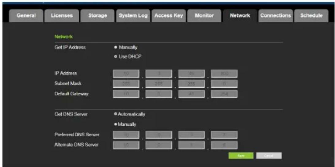
Working as a DHCP Server
For VK1200 / VK2200 only, the control box can operate as a DHCP server for automated assigning dynamic IP addresses to all of the LAN devices managed via its Control LAN. To do this, follow the steps below.:

- From the Get IP Address drop-down list, select Enable DHCP Server, and optionally change the network settings of the ATEN Control System, namely IP address, subnet mask, and default gateway.
- Next to IP Assigned Range, define the desired range of IP that can be used for assigning IP addresses to the connecting IP devices.
- Next to Lease Time, define the amount of time an assigned IP address becomes available for use after the IP device it is previously assigned to has been inactive for.
Connections
The Connections tab allows you to view the connection statuses and IP addresses of licensed devices, ATEN Keypads, and ATEN Expansion Boxes.

Schedule
The Schedule tab lists scheduled events predefined using the ATEN Configurator. You can use this tab to do the following:
- Enable or disable scheduled events.
- Enable or disable scheduled days
For details on setting up scheduled events, see Scheduled Events, page 220.
![General Licenses Storage System Log Access Key Monitor Network Connections Schedule Schedule Event Name Repeat Time OPEN Weekly Sunday [08:00] Monday [08:00] Tuesday [08:00] Wednesday [08:00] Thursday [08:00] Friday [00:00] Saturday [00:00] CLOSE Weekly Sunday [18:00] Monday [18:00] Tuesday [18:00] Wednesday [18:00] Thursday [18:00] Friday [00:00] Saturday [00:00]](/content/2026/05/1091984/images/477c9aa5dee4ccad8c1c7a1efe54bff5e6d5b3b3560941f710bab5d787cbe05f.jpg)
Security
The Security tab allows you to configure SSL and TSL settings to secure the browsing sessions between your computer and the ATEN controller's web interface.
- SSL Certificate: To enable SSL encryption on the controller, purchase and obtain an SSL certificate from a trusted certifying authority and click Upload to apply the certificate.
TLS Support: Each ATEN controller supports TLS 1.0, 1.1, and 1.2 to allow communications with devices supporting different versions of the TLS. If you have any security concerns, disable the Enable TLS 1.0 and TLS 1.1 setting to only allow communications among devices that support TLS 1.2 and click Save.
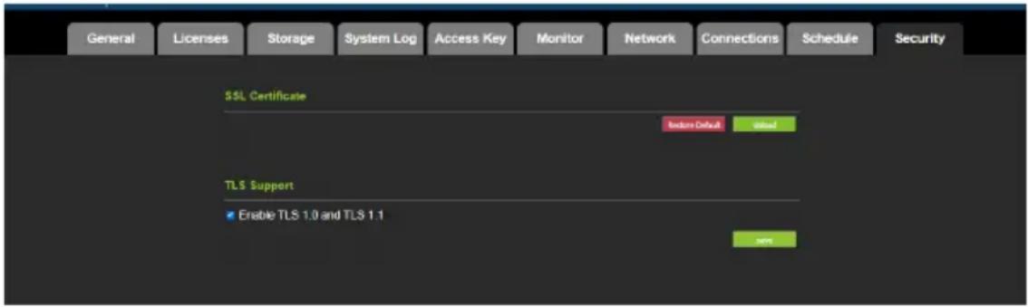
Chapter 4
ATEN Configurator (VK6000)
Overview
The ATEN Configurator (VK6000) is a GUI-based management tool that helps you set up and configure the connected hardware and create control interfaces (Viewer), to be used on control interfaces including mobile devices, ATEN Keypads, ATEN Control Pads and ATEN Touch Panel.
Installing ATEN Configurator
To install the ATEN Configurator software, do the following:
- Download ATEN Configurator.
a) Visit the ATEN download page.
http://www.aten.com/global/en/support-and-downloads/downloads/
b) Search for "VK6000". A list of downloads for VK6000 appear.
c) Click ATEN_configurator_software_x.x.xxx.zip to download.
- Open the downloaded zip file and double-click
ATEN_configurator_software_x.x.xxx.exe to run the setup. This screen appears.

3. Click Next. This screen appears.
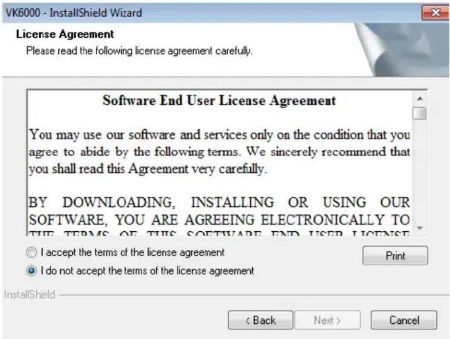
4. If you agree with the License Agreement, select I accept the terms of the license agreement, and click Next. Click Print to print the Software End User License Agreement. This screen appears.

- To change the destination location, click Change. Click Next to proceed using the default location. This screen appears.

- Click Install. When the process is complete, a confirmation message appears.
- Click Finish.
Getting Started Tasks
After you have installed and launched the ATEN Configurator, the main screen (page 98) appears. You will be guided to create and configure a project using the 4 tabs in the Configurator's interface, as illustrated below.

flowchart
graph LR
    A["1. Project"] --> B["2. Device"]
    B --> C["3. Design"]
    C --> D["4. Upload"]
Hint: You can click the tabs to switch among different pages for configuration.
The steps below provides an overview of the getting started tasks.
-
In the Project tab, do the following.
-
Provide information about the ATEN controller that you have set up.
- (Optional) Provide client information for the specified ATEN controller.
Click Add Controller if you have more than one controller in the environment.
Click Start Project to proceed.
-
In the Device tab, do the following.
-
Connect each controller with its managed devices by adding them to the controller's Device Configuration list, enter the connection settings, and specify the physical locations.
- (Optional) Add another controller and/or Expansion Box to the project by clicking Add Controller or Expander.
- Connect the Expansion Box with its managed devices by adding them to the Expansion Box’s Device Configuration list.
For more details, see Configuring Managed Devices, page 109.
Click Design or the Viewer tab to proceed.
![ATEN Configurator - [Untitled Project.vkproj*] File Edit View Object Tools Windows Help 1. Project 2. Device 3. Design 4. Upload Controll... Viewer ... Unizon VK2200-ID01 × Device Configuration](/content/2026/05/1091984/images/48a80ad5abd0007ef2acd9aa8a66a6305d7c98395a25bb609438073624d7f1d6.jpg)
-
In the Design tab, do the following.
-
Create and configure a control interface (Viewer). For more information, see Configuring the Control Interface (Viewer), page 127.
- (Optional) Set up scheduled events to automatically carry out specified actions.
♦ (Optional) Add additional conditions and actions to buttons using Flags. For details, see Flag, page 194. - (Optional) Create a sequence of actions for a button by creating a Macro. For details, see Macro, page 218.
-
(Optional) Create a Variable for a device setting that is controlled by two or more objects in one control interface. For details, see Variables, page 222.
-
In the Upload tab, upload this Viewer to the controller. For details, see The Upload Tab, page 245.
Main Screen
Overview
Double-click the Configurator.exe shortcut to open the ATEN Configurator software. The Project page appears:
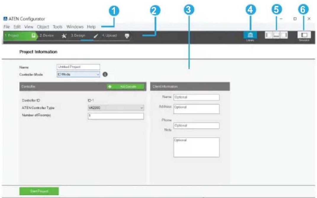
| No. | Control Description | |
| 1 | Menu Bar The menu bar contains a group of the Configurator ‘s main functions by category. For details, see Menu Bar, page 99. | |
| 2 | Project Bar | The Project Bar contains four tab and the Library icon. Each tab relates to a step required to set up the project. Each step and the Library can be selected by clicking on the bar. |
| 3 | Interactive Display Panel | This is the main work area. The page that appears here reflects the project tab that is selected. |
| 4 | Library The Library contains the devices, graphic, flag, macro, and monitor databases. Each section allows you to add custom items or choose from ready made selections. | |
| 5 | Toggle Bar These three icons are used as a toggle to show or hide the right, left and bottom control panel. | |
| 6 | Simulator The Simulator button is used to test the Viewer after it is created in Design. The simulator allows you to tryout the interface as it would work on a mobile device but without actually controlling devices. Use the mouse to click through the page links. | |
Menu Bar
The menu bar contains the Configurator's main functions arranged by category. Refer to the table below to find out what each function does.
| Menu Sub-Menu Description | ||
| File New | Project Select to create a new project. | |
| Open Project Select to browse and | open a previously saved project. | |
| Restore Project from Controller Do | wnloads a previously backed up project from a controller. | |
| Close Closes the current project and | returns to the Project tab. | |
| Save Select to save changes to the | current project. | |
| Save as Use this option to save the | project as a different name. | |
| Export Viewer to USB(Not supported by ATEN Control Pad) | Exports Viewers and an access key to a USB drive. After exporting the data onto a USB drive, plug the USB drive into the Control Box's USB port to upload the Viewer files and the access key. These files can only be read by the Control Box and are not project files that can be opened by the ATEN Configurator software. | |
| Project Report Click to save a PDF | file that contains detailed information about each part of the current project. | |
| Add KNX Device | Import ETS Project | |
| Add Custom KNX Device | ||
| Recent Projects Select to view a list of recent projects that can be clicked on to open. | ||
| Exit Select to close the project and | exit. | |
| Menu Sub-Menu | Description | ||
| Edit Undo | Select to undo a change when editing a Viewer in Create & Design Viewer. | ||
| Redo Select to redo a change when editing a Viewer page in Create & Design Viewer. | |||
| Cut/Copy/Paste Select to cut, copy | or paste text and objects when editing a Viewer page in Create & Design Viewer. When used to copy and paste a button, both the General and Action properties are copied. | ||
| Paste Graphic Only Select to paste | a button's image but not its Action properties in Create & Design Viewer. | ||
| Delete Select to delete highlighted | text and images when editing a page in Create & Design Viewer. | ||
| Delete Action Only Select to delete | the Action properties of a button in Create & Design Viewer. | ||
| Select All / Deselect All Use either | option to select or unselect all objects when editing a viewer page in Create & Design Viewer. | ||
| Preferences Display | Language | Use to select the language for the interface. | |
| SSH Destination Click to choose the location of the executable for the SSH Client software. To execute the program, go to Tools > SSH Client. | |||
| Interface Check a box to enable the feature described below:Show Welcome Page: displays the Welcome screen when the ATEN Configurator software opens.Auto Page Creation: automatically creates a Viewer page in Create Viewer & Design, for every hardware device that is configured in Select Device & Configuration.Show Password: displays the characters of the access key in the Edit Access Key dialog box.Automatically check for updates: automatically checks for updates and notify the user when an update is available. | |||
| Menu Sub-Menu Description | ||
| View | These options are available from Create Viewer & Design Edit Viewer. | |
| Zoom Zooms the Viewer page to 25%, 50%,75%, 100%, 200% or Fit in Window.Note:A mouse wheel can be used to zoom the Viewer page in or out. | ||
| Project Information Select to go to | Project Information. | |
| Device Configuration Select to go to | Select Device &Configuration. | |
| Viewer Design Select to go to Create Viewer & Design. | ||
| Project Upload Select to go to Search & Upload. | ||
| Properties Select to show/hide the | Propertieswindow when editing a Viewer page. | |
| Align to Grid Select to automatically | align objects withthe grid. This places objects in perfectalignment with the grid dots when theyare moved. Use Show Grid to displaythe grid dots. When Align to Grid is notselected, objects can be placedanywhere on the page. | |
| Show Grid Select to display the grid | dots on thepage. Use with the Align to Grid optionto set objects in perfect alignment on thepage. | |
| Show Object ID Select to show object | ID at the top-rightcorner of each object. An object ID isused to specify an object in someconfiguration. | |
| Menu Sub-Menu Description | |||
| Object | These options are available from Create Viewer & Design Edit Viewer. | ||
| Button Adds a button to the Viewer | page. | ||
| Text Adds a text box to the Viewer | page. | ||
| Image Adds an image to the Viewer | page. | ||
| Scroll View Adds a scroll box to the | Viewer page,then double-click it to add buttons. Use the box as a scroll window to easily access a list of buttons on the page. | ||
| Video Adds a video box which allows you to view video. The video box can be resized using the Properties sidebar or by dragging a small box on the boarder to resize it to the desired shape. | |||
| Slider Bar Adds a slider bar to the | Viewer page.Slider bars are used to adjust the value of a device setting, such as the volume level of an audio device. | ||
| Menu | Sub-Menu | Description | |
| Object PowerPoint Control Template Adds a PowerPoint Control template to the Viewer. This control template is used to control PowerPoint files saved in a target computer. | |||
| Menu Sub-Menu Description | |||
| Object Align Left Aligns two | or more selected | objects to the Left side of the object that is selected last. | |
| Center Aligns two | or more selected objects to the horizontal position of the object that is selected last. | ||
| Right Aligns two or | more selected objects to the Right side of the object that is selected last. | ||
| Top Aligns two or | more selected objects to the Top side of the object that is selected last. | ||
| Middle Aligns two | or more selected objects to the vertical position of the object that is selected last. | ||
| Bottom Aligns two | or more selected objects to the Bottom side of the object that is selected last. | ||
| Make Same Size | Width Resizes two | or more selected objects to the same width of the object that is selected last. | |
| Height Resizes two | or more selected objects to the same height of the object that is selected last. | ||
| Both Resizes two | or more selected objects to the same width and height of the object that is selected last. | ||
| Space Evenly | Across Page Width | Spaces two or more selected objects evenly across the width of the page. | |
| Across Page Height | Spaces two or more selected objects evenly across the height of the page. | ||
| Between Objects Horizontally | Adjusts the horizontal space between three or more selected objects to the average distance between each of the selected objects. | ||
| Between Objects Vertically | Adjusts the vertical space between three or more selected objects to the average distance between each of the selected objects. | ||
| Menu | Sub-Menu | Description | |
| Tools Database Generator Opens the ATEN | Database Generatorwhich is used to manually add andconfigure hardware devices. This iswhere you can create custom devices toadd to My Device Library. See ATEN Database Generator, page 249, fordetails. | ||
| Simulator The Simulator is used to | test a Viewer'sinterface after it has been created in Design. The simulator allows you totryout the interface as it would work on amobile device but without actuallycontrolling devices. Use the mouse toclick through the page links. | ||
| SSH Client This runs the SSH Client software | |||
| Windows | New Page Click to create a new Viewer page orselect a page to open in Create Viewer& Design. | ||
| Help About | Provides the firmware version andsupport information for the Configuratorsoftware. | ||
| Check for Updates Checks if ATEN | Configurator is up-to-date. | ||
| Training Videos (Basic) Click to see how-to videos on tasksinvolved in configuring a project file. | |||
| Training Videos (Advanced) Click to see how-to videos on usingadvanced features such as creating avariable, creating a driver usingdatabase generator, and more. | |||
| Driver Downloads Click to download drivers for third-partydevices. | |||
| What's New Click to see new features and functionsin this version. | |||
Creating Projects
The Project tab allows you to enter details about the installation to start the project. Enter the information using the table below as a guide.
![ATEN Configurator - [] File Edit View Object Tools Windows Help 1 Project 2 Device 3 Design 4 Uploaded Project Information Name Untitled Project Controller Mode ID Mode Controller Add Controller Controller ID ID-1 ATEN Controller Type VK2200 Number of Room(s) 1 Controller ID ID-2 ATEN Controller Type VK1200 Number of Room(s) 1 Remove Controller Controller ID ID-3 ATEN Controller Type VK0200 Number of Room(s) 1 Remove Controller Client Information Name Optional Address Optional Phone Optional Note Optional StartProject](/content/2026/05/1091984/images/cc10aecb32b3ee181727a59bf20f1d6a36865094831c15248f89d84d04f752a2.jpg)
Control Description
Name Enter the project name you are setting up. You can create multiple projects but for most installations only one project is required.
| Control Description | |
| Controller Mode | Click to specify how controllers in this project file connect to Expansion Boxes and Keypads.♦ ID Mode (default)♦ Controllers connect to Expansion Boxes or ATEN Keypads by matching controller ID, as set using the controller ID switch on the controller panel and configured in the project file (see Controller ID field below) with the controller ID set on the Expansion Box or Keypad.♦ Using the ID mode, a controller can connect up to 8 Keypads of the same model and 8 Expansion Boxes of the same model.♦ IP Mode♦ Controllers connect to Expansion Boxes / ATEN Keypads through their IP address.Note: When IP Mode is selected, controllers do not use any ID settings on ATEN Keypads or Expansion Boxes as the basis for their connection. However, the controller ID on the controller panel and the project file need to match to successfully apply the configuration.♦ Using the IP mode, the maximum numbers of ATEN Expansion Boxes that controllers can connect are as follows:♦ VK0100 / VK0200: 16♦ VK1100A / VK2100A: 32♦ VK1200 / VK2200: 64♦ Using the IP mode, the maximum numbers of ATEN Keypads that controllers can connect are as follows:♦ VK0100 / VK0200: 10♦ VK1100A / VK2100A: 16♦ VK1200 / VK2200: 32 |
| Add Controller Click to | add controllers to the project. The number added should match the number of controllers installed. A project can have up to 16 controllers. |
| Controller ID Displays | the controller ID. Make sure the ID in this field matches the ID on the controller so that the project file will be uploaded to the specified controller. |
| ATEN Controller Type | Select the model for the controller. |
| Number of Rooms Enter | the number of rooms each controller will control. Each hardware device you add will be associated with a room. When buttons are configured in the Design tab, you can select a Room under Button Action to filter the Device list so that only hardware in that room appears. This link between the controller, devices and room is how the Viewer knows which devices to control. |
| Name Enter the client name associated with the project. | |
| Address Enter the client address associated with the project. | |
| Phone Enter the client phone number associated with the project. | |
| Remove Controller Click to delete a controller from the project. | |
| Start Project | Click to begin configuring hardware devices. The Select Device & Configuration tab will open. |
Configuring Managed Devices
Overview
The Device tab is used to configure controller ports according to the connected hardware device.
![ATEN Configurator - [Untitled Project vkproj*] File Edit View Object Tools Windows Help 1 Project 2 Device 3 Design 4 Upload Control Viewer Unión VK2100-ID01 VK2100-ID01 Type Device Mode Room Unizon Serial 1 None RS232 Room-1 Serial 2 None RS232 Room-1 Serial 3 None RS232 Room-1 Serial 4 None RS232 Room-1 Serial 5 None RS232 Room-1 Serial 6 None RS232 Room-1 I/O 1 None Output Room-1 I/O 2 None Output Room-1 I/O 3 None Output Room-1 I/O 4 None Output Room-1 IR 1 None IR Room-1 IR 2 None IR Room-1 IR 3 None IR Room-1 IR 4 None IR Room-1 Relay 1 None Room-1 Relay 2 None Room-1 Relay 3 None Room-1 Relay 4 None Room-1 Ethernet 1 None Room-1 Add Context & Options Add Port Device Configuration VK2100-ID01 Properties Name AddDevice Category Audio Contenance Blank Model Version Connection Settings Board Plate: 36000 Data Bit: 8 Stop Bit: 1 Party Name Advanced](/content/2026/05/1091984/images/a057806ea03a139e2de06d8068a588973f547a8bd5dfec25599dc2a4cb7c415f.jpg)
| Control Description | |
| DeviceConfigurationList | This section lists the ports for each controller, their connected device, connection mode, device location (room) and if the device is managed by UnizonTM. Click on a controller, expansion box or Room in the left sidebar to display the ports. Each port needs to be configured according to the hardware device connected to it. For details, see Left Sidebar, page 110. |
| Left Sidebar The | left sidebar provides a tree view of the ATEN Control System deployment in each project. Use the sidebar to add/remove a controller, Expansion Box, or Room. |
| Properties This | section allows you to add and configure controllers, Expansion Boxes, managed devices, and rooms. For details, see Configuring the Control Interface (Viewer), page 127. |
| Device Library | Click this icon to open the Library on the Device Library tab which contains a database of hardware devices that can be added to the Device Configuration list. For details, see Device Library, page 126. |
Left Sidebar

Controller
The Left Sidebar provides a tree view of the controllers, Expansion Boxes, and rooms. Each controller in the tree view represents a controller with one or more rooms it manages. Selecting a controller allows you to configure its ports. When a port is configured for a device, it appears listed under the Room.
Each controller must contain at least one room. When installing multiple controllers in one room, add a room with the same name to each controller.
Each controller name ends with an ID number: e.g. VK2200-ID02. This ID number is automatically generated when the controller is added into the project. You can also configure this ID in the controller properties settings.
Use this number to set the Controller ID Switch on the rear of the controller. This links the controller in the software to the physical device being installed.
Right-click a controller to Add Room or Delete Controller.
Room
Each room is associated with a controller and a Viewer so that the information is uploaded to the correct controller to control the hardware devices. Right click a room to Delete or Rename the room. Use the buttons at the bottom of the sidebar to Add Room.
Expansion Box
ATEN Expansion Boxes connect over a network to add ports to the controller via its Ethernet port. Clicking Add Controller or Expander opens a window which allows you to select a device to add.
Device Configuration List
The Device Configuration page lists the controller ports by type. Click a port to view its Properties. Double-click a port to open the ATEN Device Library and search for the hardware device to configure the port. Configure each port according to the hardware device connected to it.
| Device Configuration | ||||
| VK2100-ID01 | ||||
| Type Device Mode Room Unizon | ||||
| Serial 1 None RS232 Room-1 | ||||
| Serial 2 None RS232 Room-1 | ||||
| Serial 3 None RS232 Room-1 | ||||
| Serial 4 None RS232 Room-1 | ||||
| Serial 5 None RS232 Room-1 | ||||
| Serial 6 None RS232 Room-1 | ||||
| I/O 1 None Output Room-1 | ||||
| I/O 2 None Output Room-1 | ||||
| I/O 3 None Output Room-1 | ||||
| I/O 4 None Output Room-1 | ||||
| IR 1 None IR Room-1 + Add More Devices | ||||
| IR 2 None IR Room-1 + Add More Devices | ||||
| IR 3 None IR Room-1 + Add More Devices | ||||
| IR 4 None IR Room-1 + Add More Devices | ||||
| Relay 1 None Room-1 | ||||
| Relay 2 None Room-1 | ||||
| Relay 3 None Room-1 | ||||
| Relay 4 None Room-1 | ||||
| Ethernet 1 None Room-1 + Add More Devices | ||||
| VK224-ID01 | ||||
| Type Device Mode Room Unizon | ||||
| Serial 1 None RS232 Room-1 | ||||
| Serial 2 None RS232 Room-1 | ||||
| Serial 3 None RS232 Room-1 | ||||
| Serial 4 None RS232 Room-1 | ||||
| VK248-ID01 | ||||
| Type Device Mode Room Unizon | ||||
| Relay 1 None Room-1 | ||||
| Relay 2 None Room-1 | ||||
| Relay 3 None Room-1 | ||||
| Control Description | |
| Type Lists the | ports of the controller. |
| Device Lists the | device name entered in Properties. |
| Mode Lists the | port's communication mode. Click an arrow to select options:♦ Serial: RS-232, RS-422, or RS-485♦ I/O: Input (VDC), Input (Dry Contact) or Output♦ IR: IR or R-S232 |
| Room Lists the | room selected for a device. The rooms available depend on the number of rooms added to the controller. No drop-down menu appears if there is only one room. Each controller must have at least one room. Select the room where the device is installed. |
| UnizonTM Select | ct this option to allow UnizonTM to manage and monitor the corresponding device.Note:Configuration will also be required on UnizonTM for this feature to work. For an overview of how to set up the function, see Centralized Monitoring and Control via UnizonTM , page 237. |
| + Add More Devices | RS-422, R-S485, LAN and IR ports can cascade additional devices that are connected to the first unit. IR ports can cascade 1 device, RS-422 and RS-485 ports can cascade up to 2 devices and LAN ports can cascade up to 25 devices. |
Adding Devices to the Device Configuration List
Adding Non-KNX-Compliant Devices to ATEN Configurator
To add devices that are not KNX compliant, use one of the following methods.
Via ATEN Device Library or My Library
- In the Device Configuration list, click a port where you have physically installed a device.

- Click library. In the pop-up window, click the drop-down list to select ATEN Device Library or My Device Library, and then double-click an item to add the device. The selected device is added to Device Configuration.
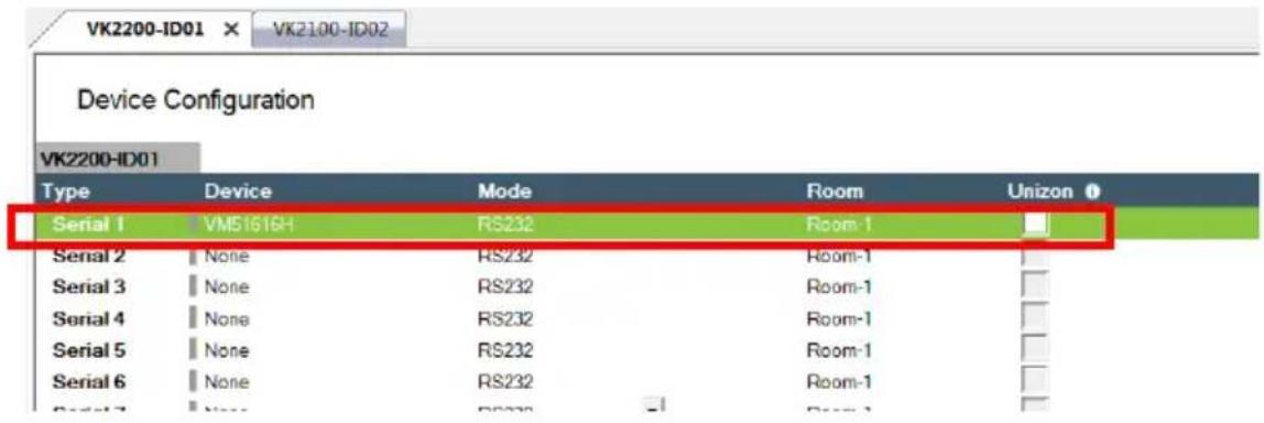
Via the Properties Column
- In the Device Configuration list, click a port where you have physically installed a device.

- Use one of the following to add a device.
Select from Library:
Use this method to automatically bring in default settings for the selected device.
(a) Click the arrow button and select Add device from the Library to open the Library.

(b) Click the drop-down list to select ATEN Device Library or My Device Library, and then double-click an item to add the device.
- Specify and configure settings
Use this method to type and configure each setting for the device. When the configuration is complete, click Add Device.
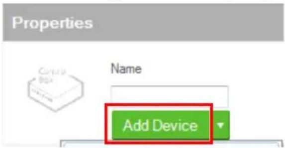
Note:
If the device is not in the Library, create the device using Database Generator. For details, see Editing / Adding a New Device, page 256.

Adding KNX Devices
There are two ways to add KNX devices into ATEN Control System projects:
- Add a KNX device individually (page 115)
- Import a pre-configured ETS project (page 116)
Adding a KNX Device
- In the Devices tab, go to File > Add KNX Device > Add Custom KNX Device. A KNX IP Interface (with a default room) is added.

- On the controller where you wish to add the KNX device, right-click the controller and then select Add KNX Room > Default Room.
The KNX device is added.

Importing an ETS Project
- In the Devices tab, go to File > Add KNX Device > Import ETS Project. The configurations for your KNX devices appear in the Controller tab on the left-side bar.
- In the Controller tab, click on KNX IP Interface and type its IP address and port in the Properties column.
Device Properties
The Properties panel provides information and configuration fields for controllers, Expansion Boxes, remote devices, or rooms. Click a device or room from the left sidebar or the Device Configuration list to display its properties.
Controller Properties

Click a controller from the left sidebar or from the Device Configuration list to configure or view the following properties.
◆Name: Displays the device model.
◆Controller ID: Sets the controller ID. With the controller set to ID mode (Creating Projects, page 106), the controller connects to ATEN Expansion Box and Keypad by matching this ID with that set on the Expansion Box or Keypad.
Expansion Box (Expander)
Click an expansion box from the left sidebar or from the Device Configuration list to configure or view the following properties

◆ Name: Displays the device model.
- Expander ID: Select the expander ID. Make sure the ID matches the one set physically on the Expansion Box.
- IP Address: Specify the IP address of the expansion box. This setting is only required when the connection mode (with the controller) is set to IP mode. For more information, see Creating Projects, page 106.
Serial Device Properties
Properties

Name
VM1600
Remove
Category
Video Matrix Switches
Brand
ATEN
Model
VM1600
Version
V1.3.126

Connection Settings
Baud Rate
19200

Data Bit

Stop Bit

Parity
None
Advanced
Delay Interval

Seconds
Feedback Timeout
Seconds
End Character


Keep Connection Alive
Format

ASCII

HEX
Command

Interval
1.0
Seconds (1.0\~60.0)
Click a serial device from the Device Configuration list to configure its properties.
◆Name: Displays the device model.
- Add Device: Use this button to add devices. For details, see Adding Non-KNX-Compliant Devices to ATEN Configurator, page 113.
◆Category: Displays the category of the selected device.
- Brand: Displays the brand of the selected device.
◆Model: Displays the model of the selected device.
◆Version: Shows the firmware version selected for the device. Use the drop-down menu to select a different firmware version. Click the menu box next to the version number to open a PDF with the version history. The version history and different versions for a device can be manually added/updated via the Database Generator (see step 3 of Editing / Adding a New Device, page 256).
- Connection Settings: Click the drop-down lists to configure the baud rate, data bit, stop bit, parity settings, and flow control for the selected serial device.
◆Advance Settings: Click Advanced to display the following settings.
◆Delay Interval: Sets a time delay for each command before they are sent to the device.
- Feedback Timeout: Sets the maximum interval that the controller allows in between parts of a feedback message. The controller uses this value to identify the end of a message.
- End Character: Type the end-of-text character of the device to inform controller the end of a message and to shorten the response time.
- Keep Connection Alive: The controller sends a command to the serial device to maintain the connection and avoid timeout issues.
◆ Command: Type a command to be sent to the selected device.
- Interval: Type the interval at which the controller sends the command.
I/O Device Properties
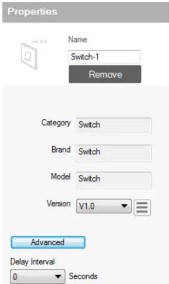
Click an I/O device from the Device Configuration list and select Input (VDC), Input (Dry Contact), or Output to configure its properties.
◆Name: Displays the device model.
- Add Device: Use this button to add devices. For details, see Adding Non-KNX-Compliant Devices to ATEN Configurator, page 113.
◆Category: Displays the category of the selected device.
◆Brand: Displays the brand of the selected device.
◆Model: Displays the model of the selected device.
◆Version: Shows the firmware version selected for the device. Use the dropdown menu to select a different firmware version. Click the menu box next to the version number to open a
PDF with the version history. The version history and different versions for a device can be manually added/updated via the Database Generator (see step 3 of Editing / Adding a New Device, page 256).
- Lower Threshold & Upper Threshold: Set the thresholds according to the hardware device you are connecting and then configure a Monitor (see page 196).
◆ Advance Settings: Click Advanced to display the Delay Interval setting.
- Delay Interval: Sets a time delay for each command before they are sent to the device.
IR/Relay Device Properties

Click an IR/Relay device from the Device Configuration list to configure its properties.
◆Name: Displays the device model.
- Add Device: Use this button to add devices. For details, see Adding Non-KNX-Compliant Devices to ATEN Configurator, page 113.
◆Category: Displays the category of the selected device.
◆Brand: Displays the brand of the selected device.
◆Model: Displays the model of the selected device.
◆Version: Shows the firmware version selected for the device. Use the dropdown menu to select a different firmware version. Click the menu box next to the version number to open a PDF with the version history. The version history and different versions for a device can be
manually added/updated via the Database Generator (see step 3 of Editing / Adding a New Device, page 256).
◆ Advance Settings: Click Advanced to display the Delay Interval setting.
- Delay Interval: Sets a time delay for each command before they are sent to the device.
Ethernet Device Properties
Properties

Name
ControlAssist
Remove
Category
Tool
Brand
ATEN
Model
ControlAssist
Version
V1.2

Connection Settings
Protocol Type
HTTPS
IP Address
10.3.41.121
Port
6277
Username
administrator
Password
********

Delay Interval
0

Seconds
Click an Ethernet device to configure its properties.
◆Name: Displays the device model.
- Add Device: Use this button to add devices. For details, see Adding Non-KNX-Compliant Devices to ATEN Configurator, page 113.
◆Category: Displays the category of the selected device.
◆Brand: Displays the brand of the selected device.
◆Model: Displays the model of the selected device.
◆Version: Shows the firmware version selected for the device. Use the drop-down menu to select a different firmware version. Click the menu box next to the version number to open a PDF with the version history. The version history and different versions for a device can be manually added/updated via the Database Generator (see step 3 of Editing / Adding a New Device, page 256).
- Connection Settings
Depending on the selected protocol, some of the following settings may not be required and are not displayed.
- Protocol Type: Click to select the protocol for the Ethernet device. The ATEN Control System supports control of devices via telnet, ONVIF, TCP, UDP, HTTP, HTTPS, and WebSocket. Configure the following fields as required.
IP Address: Type to assign a fixed IP address to the Ethernet device. - Port: Type to assign a communication port.
- Username & Password: Type the device's login/access credentials.
- VE Manager Password: Type the administrator password of the VE Manager to allow the controller to access video sources connected to the video extenders managed by the VE Manager.
- Auth Type: Sets the authentication type that the device uses.
- URIPath: Type the part of the WebSocket URI that follows its communication port. For example, if the URI is wss://
:31416/Dicentis/API, type Dicentis/API in this field.
SubProtocol: Type the subprotocol for the Ethernet device. This information shall be available in the device's reference or user manual. - WSS: Select to encrypt the WebSocket connection.
- Edit Additional Info:
◆ ExtHeader: Type the required data for handshake header.
◆ Extension: Type the required data for the Sec-WebSocket-Extensions header field.
- Edit Login Command: Click to edit the login command.
◆ Monitor Connection
- Check Status (ICMP): Select this option to allow the controller to send control messages to receive connection status for this Ethernet device.
Note: To allow the online/offline status to be accessible to Unizon ™ for remote management, select the Unizon ™ checkbox that corresponds to the device in the Device Configuration list.
- NOP (for Telnet only): Select this option to send a no-operation command to the remote end of a Telnet connection to maintain the connection status of the device with controller.
- Stream: To allow video streaming to the controller via RTSP, select this option and type the streaming IP address, port, and login credentials of the Ethernet device.
◆ Advance Settings: Click Advanced to display the Delay Interval setting.
- Delay Interval: Sets a time delay for each command before they are sent to the device.
- Delay after Login (for telnet only): Sets a delay (to allow a connection to be established) before the First and Second Commands are sent to the device.
- Feedback Timeout: Sets the maximum interval that the controller allows in between parts of a feedback message. The controller uses this value to identify the end of a message.
- End character: Type the end-of-text character of the device to inform controller the end of a message and to shorten the response time.
- Send command after connection (for telnet and TCP only): Sends commands to the device after a successful connection has been established.
♦ Format: Sets the command format.
- First Command: Sets the command.
Second Command: Sets the second command.
- Automatically reconnect if no return message is received: Select this option to continue reconnection attempts when no return message is received from the device.
- Keep Connection Alive (for telnet and TCP only): The controller sends a command to the device to maintain the connection and avoid timeout issues.
◆ Command: Type a command to be sent to the selected device.
- Interval: Type the interval at which the controller sends the command.
Migrating Devices to another Controller
When you migrate a managed device from one controller to another, you can have its configuration duplicated without setting it up again.
To migrate the configuration of a managed device to another controller, follow the steps below.
- Click the Devices tab.
- In the left sidebar, right-click the device you wish to migrate.
- In the pop-up menu, select Switch To, and then select the controller, and a port to which you wish to migrate. The device and its configuration is moved immediately.

Library
The Project Bar provides the Library option. Use the Device Library tab (shown below) to configure controller ports according to the connected hardware devices. The Device Library provides an extensive database of hardware devices that can be double-clicked or drag and dropped into the Device Configuration page to configure controller ports. The Device Library is discussed on the next page.

Device Library
The Device Library tab is a database of hardware devices that instantly configure controller ports. Search the library for the device connected to a controller port then add it to configure the port. For devices not in the library, use the ATEN Database Generator to create custom hardware (see page 249). Click Library on the Project bar or double-click a port on the Device Configuration page to open the ATEN Device Library.


- Add a device by clicking Add to Project or by drag & drop.
- To search for a device type keywords into the box and click
- Click a tab to filter by All, Serial, DO, IR, Relay or Ethernet.
- Click headings to sort by Brand, Device Type, Model or Version.
◆ Use the drop-down menu to select:
♦ ATEN Device Library – ATEN’s database of hardware devices.
- My Device Library – Devices added from the Database Generator.
- Create Device – Opens the Database Generator to create custom hardware devices for My Device Library (page 250).
Configuring the Control Interface (Viewer)
This section provides information on how to configure a control interface, the viewer, for your control system and the functions of different control objects.
Getting Started with Configuring Viewers
| Step | Action Refer to | |
| 1. | Understand the usages of Pages and Subpages. | The Design Tab, page 128 |
| 2. | Plan and consider the following before creating the viewer:required control actions and suitable control elementsplacement of these control elements among Pages, and on Subpages if needed | Control Object Properties, page 145Viewer List, page 129 |
| 3. | Create a viewer. Adding Viewers, page 133 | |
| 4. | Based on your planning, add the required Pages / Subpages. | Adding / Removing a Page, page 137Configuring a Subpage, page 138 |
| 5. | Add and configure control objects on the created Pages / Subpages. | Configuring Control Objects, page 142 |
The Design Tab
Use the Design tab to configure viewers for your control system. A design tab contains following elements to help you create, configure, and manage your viewers:
② Control / Monitor List
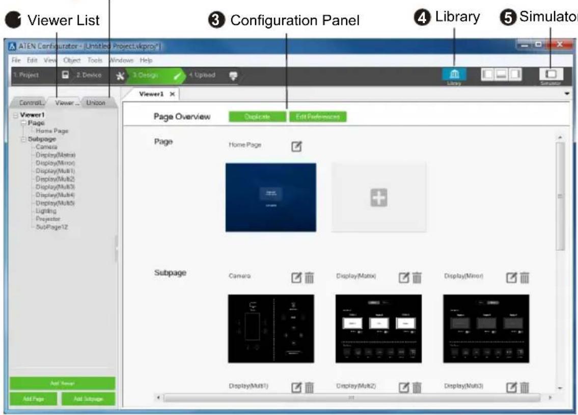
① Viewer List
The Viewer List provides a tree view of added Viewers and the associated control pages, as illustrated on the right.
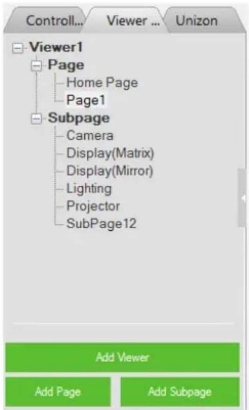
flowchart
graph TD
    A["Viewer1"] --> B["Page"]
    B --> C["Home Page"]
    B --> D["Page1"]
    E["Subpage"] --> F["Camera"]
    E --> G["Display(Matrix)"]
    E --> H["Display(Mirror)"]
    E --> I["Lighting"]
    E --> J["Projector"]
    E --> K["SubPage12"]
In a Viewer, you may find the following page types:
Home Page: This is the main page (for mobile devices and ATEN touch panel) or the key layout (for ATEN Control Pads and Keypads). A Home Page typically contains buttons that redirect to frequently used features and control pages, such as display, lighting, air conditioning, etc.

Page: This is a full-size control page to which you can redirect by tapping an associated button or icon from the Home Page or other Pages.
Subpage: A Subpage is a reduced-size control page that is embedded within a Home Page or Page through an adjustable frame (the green frame as illustrated below), called the iFrame. The advantage of using subpages is that it allows you to retain some elements of the page, such as buttons of a menu bar or a company logo, while switching among different subpages. In the example below, this page is designed to have a menu bar on the left and a reserved area (iFrame) for displaying three subpages that can be switched to by tapping the menu options on the left.

Use Viewer List to add, remove, or edit Viewers and the associated pages. More specifically, you can use the Viewer List to do the following tasks:
◆ To add a new Viewer, click the Add Viewer button.
- To add a new Page or Subpage, click the corresponding button at the bottom.
◆ To delete, rename, or copy an added page, right-click it from the list.
- To duplicate the visual design of a control page (without its configurations), right-click it to select Copy, and right-click the target Page or Subpage category and select Paste.
- To open a control page, click the Page or Subpage from the Viewer list, the Page / Subpage appears as a separate tab in the configuration panel.
- To see a thumbnail of the added control pages within a Viewer, click a Viewer from the list. This Viewer appears as a tab in the configuration panel. For example:
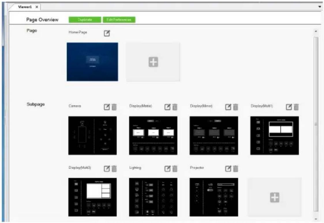
② Monitor / Control List
The monitor / control list shows the functions and settings monitored or controlled by ATEN Unizon™, categorized by device type. For more information about remote management via ATEN Unizon™, see Centralized Monitoring and Control via Unizon™, page 237.

3 Configuration Panel
The configuration panel is where the Viewer overview and control pages open in tabs for configuration.
4 Library
The Library is a repository of built-in and user-created features and functions, including graphics (page 191), flags (page 194), monitoring events (page 196), macros (page 218), schedules (page 220), and variables (page 222). For an overview of these functions, see Library, page 190.
5 Simulator
Use the Simulator button to simulate the control elements on your Viewer (without actual effect on controller-managed devices). Use the mouse to click through the page links.
Note: To view how Subpages appear, click the iFrame of the Subpage and select the Subpage you want to preview for the Preview Subpage setting. Your configuration for the selected Subpage appears.

Adding Viewers
Deciding How Many & What Viewer to Create
Scenario 1
If you have 4 control devices in your project – one ATEN Control Pad, two ATEN Keypads (sharing identical key layout and control functions with each other, but different with the Control Pad), and an iPad, you will need to create 3 viewers, as illustrated on the right.
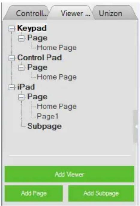
flowchart
graph TD
    A["Keypad"] --> B["Page"]
    B --> C["Home Page"]
    D["Control Pad"] --> E["Page"]
    E --> F["Home Page"]
    G["iPad"] --> H["Page"]
    H --> I["Home Page"]
    H --> J["Page1"]
    H --> K["Subpage"]
Scenario 2
If you have 3 control devices in your project – one ATEN Control Pad and two ATEN Keypads (sharing identical key layout and control functions with each other and with the Control Pad), you will need to:
- create one viewer for Control Pad
- enable the Connect Keypad setting and specify the associated Keypads. This way, the two Keypads will share the layout and control functions specified in this Viewer.
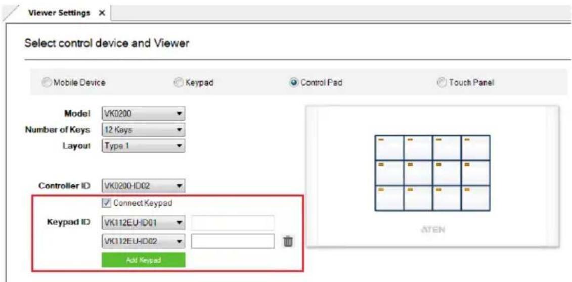
Configuring a Viewer
-
In the target project file, go to the Design tab. The Viewer Settings page appears. If not, click Add Viewer from the Viewer List.
-
Select the physical device for the Viewer.
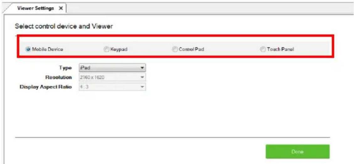
- Configure the settings for your selected device.
Mobile Device
| Setting Description | |
| Type Use this drop-down menu to select the mobile device that will be used to control hardware devices in a room. This sets the resolution for the Viewer to fit on the mobile device's screen.Choose a Custom selection to configure a screen size with the Resolution drop-down menu below it.Note: If you select Custom Windows Device – the Windows OS has a limitation for adding buttons to Viewers used on Windows mobile devices. See Windows OS Button Limitation, page 360, for details. | |
| Orientation Select one of the following display orientation:◆ Landscape: A horizontal display where the width is greater than the height.◆ Portrait: A vertical display where the height is greater than the width. | |
| Resolution Use this drop-down menu to set a custom screen resolution for the mobile device being used to control hardware devices. This option becomes available when you select one of the Custom selections from the Type drop-down menu. | |
| Display Aspect Ratio | Indicates the aspect ratio used for the selected device. |
♦ Keypad
| Setting Description | |
| Model Specify the Keypad model. | |
| Number of Keys Specify the total number of keys for your Keypad. | |
| Layout Specify the Keypad layout. This setting should match the physical Keypad layout (see page 60 for details). Depending on the total number of keys the Keypad has, you may have 1 or multiple options for this setting. | |
| Controller ID Select the ID number of the controller to which the Keypad will connect. This ID must match the controller ID set on the Keypad (see Hardware Overview, page 57). | |
| Keypad ID Select the Keypad, distinguished by its ID number to match the Keypad ID set on the Keypad (see page 64). Up to 8 Keypads can connect to one controller. | |
| blank field (after Keypad ID) | For controller to connect to the Keypad through the Keypad's IP address, make sure the controller mode setting (in the Project tab) is set to IP mode, and type the IP address of the Keypad in this field. |
| Add Keypad | Click Add Keypad to add one or more Keypads that will connect to the same controller and share identical key layout and control functions. |
- Control Pad
| Setting Description | |
| Model Specify the | model for the Control Pad. |
| Number of Keys | Specify the total number of keys for your Control Pad. |
| Layout Specify the | layout for the Control Pad. This setting should match the physical layout (see page 60 for details). Depending on the total number of keys the Control Pad has, you may have 1 or multiple options for this setting. |
| Controller ID | specify the ID of the Control Pad. |
| Connect Keypad | Select this option if the connected Keypad(s) share identical key layout and control functions with the Control Pad. |
| Keypad ID Click the | drop-down menu to specify the ID of the added Keypad. |
| blank field(after Keypad ID) | (Optional) Type the IP address of the Keypad for the controller to identify and establish connection with. Use this feature when you have more than 16 Keypads in the project or when the network switch blocks multicast signals between the Keypad and the controller. |
| Add Keypad Click | this button to add Keypad that connects to this Control Pad and shares identical key layout and control functions. |
◆ Touch Panel
| Setting Description | |
| Type Use this drop | -down menu to select the Touch Panel that will be used to control hardware devices in a room. |
| Orientation Select | one of the following display orientation:♦ Landscape: A horizontal display where the width is greater than the height.♦ Portrait: A vertical display where the height is greater than the width. |
| Resolution Indicates | the screen resolution of the selected Touch Panel. |
| Display Aspect Ratio | Indicates the aspect ratio of the selected device. |
4. Click Done to save the configuration. An overview appears.

- Add or remove the Pages / Subpages to your viewer as required.
Adding / Removing a Page
- To add a Page to a viewer, click from the Viewer list or from the viewer's Page Overview.

◆ To remove a Page, do any of the following.
◆ In the viewer list, right-click the Page and select Delete.
In Page Overview, click for the associated Page to be removed.

Configuring a Subpage
- Click the target viewer from the Viewer List, and then click add one or more Subpages to the selected viewer.
to Add Subpage
- Make sure the Page contains an iFrame for displaying Subpage controls. If not, right-click within the Page and select Add iFrame. A green frame (iFrame) appears.
- Preview a Subpage within the iFrame.
a) Click within the iFrame. The iFrame border turns blue.

natural_image
Pure geometric diagram with a rectangle and diagonal lines on a dark blue background, no text or symbols present.b) Go to Properties > Preview Subpage, and select a Subpage that you have created. The Subpage appears in the selected iFrame.
-
Adjust the size and location of the iFrame.
-
To move the iFrame, mouse over within the iFrame and then click-and-drag the iFrame.
-
To resize the iFrame, click within the iFrame, and drag-and-drop the sides or any of the corners to resize.
-
If you have two or more Subpages sharing an iFrame, create a button for switching to each of the Subpages.
a) Right-click within the page and select Add Button.
b) Configure the button properties as required.
c) Click the button, click Link Subpage, and then double-click a Subpage from the Function column to add the action. For example:
 Curtain(Relay) Condition Link Link SubPage Change Button State Change Label 2 Function Camera Display(Matrix) Display(Mirror) Display(Multi1) Display(Multi2) Display(Multi3) Display(Multi4) Display(Multi5) Lighting Projector SubPage12 3 Commands Link To: Camera to iFrame_1](/content/2026/05/1091984/images/76e8794ba8ff355e52d2c876aa6ba6c99136f630c985f2f4f8eddd9f045bd1f8.jpg)
d) Proceed to configure each button. Now the control page should contain buttons that switch to the defined Subpage.
For example:

- If you wish to keep a set of controls on the Page and only have them shown when the iFrame is closed, follow the steps below to add and configure a button for this purpose.
a) Right-click within the page and select Add Button.
b) Configure the button properties as required.
c) Click the button in the preview area, and add a Link Subpage action of any Subpage.
d) Double-click the added command and select Hide and the iFrame to be hid.

Note: The iFrame ID should match the ID indicated at the top-right corner of the iFrame in the preview area.
Duplicating a Viewer
To duplicate the Viewer along with its Pages / Subpages, do the following.
-
Click the target viewer from the viewer list. The page overview appears.
-
Click . The selected viewer is duplicated.
Viewer Control Objects
Understanding Control Objects
The ATEN control system supports a wide range of control objects, such as buttons, slider bars, videos, and PowerPoint controls that you can use and customize.
Each button has a symbol in the top left corner to indicate:
◆ “A” the button’s actions are configured correctly.
♦ “!” the button’s actions need to be modified or they will not work.
- Buttons with no symbol indicate that functions have not been added to it. For details on adding functions, see Button / Slider Bar / Dial Kit Actions, page 166.
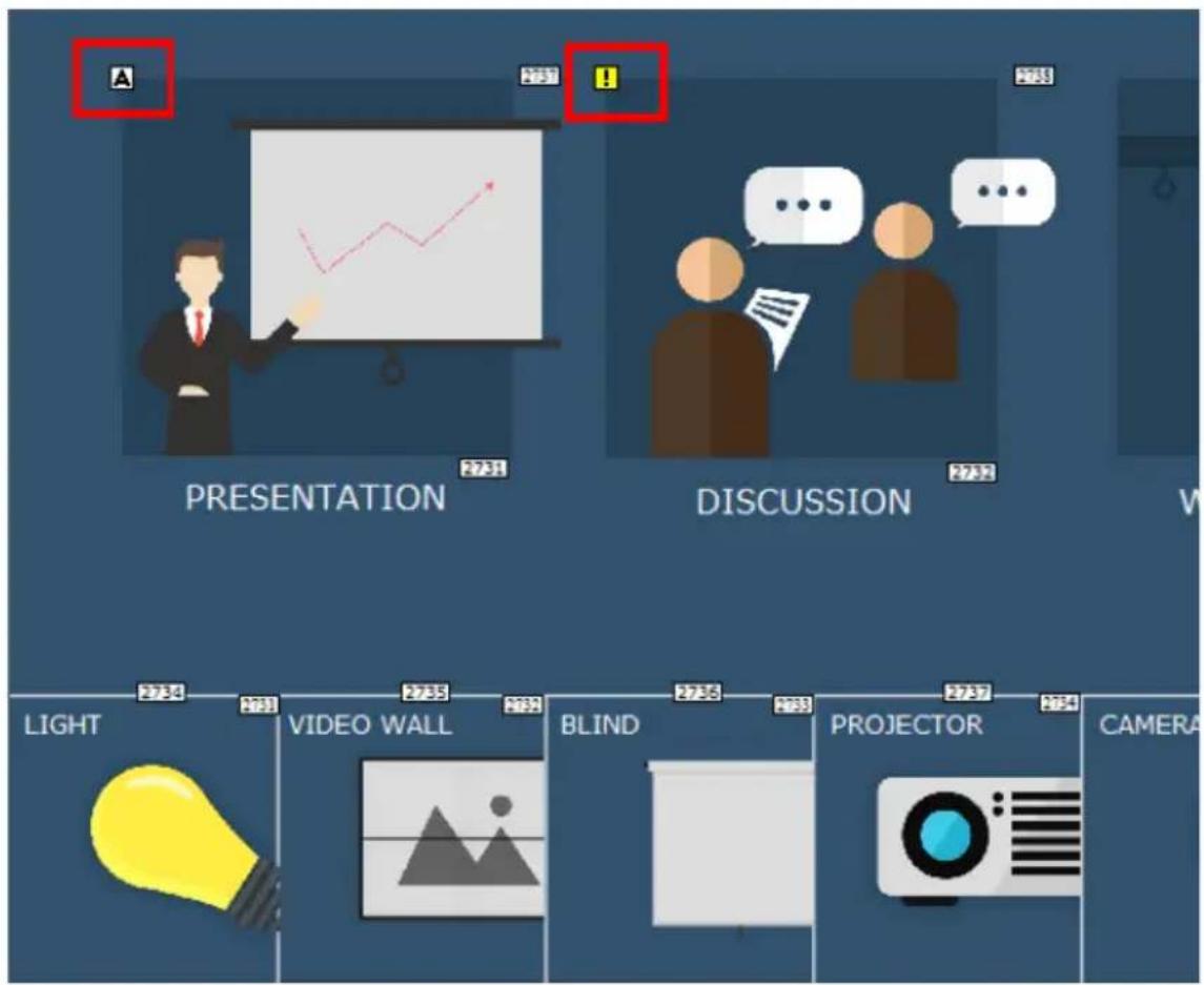
flowchart
graph TD
    A["PRESENTATION"] --> B["PRODUCTION"]
    B --> C["PROJECTION"]
    C --> D["LIGHT"]
    D --> E["VIDEO WALL"]
    E --> F["BLIND"]
    F --> G["CAMERA"]
Each object is identified by an ID at the top right corner. These IDs are assigned in the order of creation. These IDs help identify a label when configuring a Change Label (page 184) or a button when configuring a Change Button State (page 183).
Configuring Control Objects
-
Use one of the following methods to open the Page you wish to configure.
-
Click the Page from the Viewer List.
- Click its associated Viewer from the Viewer List to open the Page overview and then click to open the Page.
The Page opens in a tab. For example:

- To add a control object, right-click any space in the Page, and select an object from the pop-up menu.
Note:
- For detailed information of each object type, see Control Object Properties, page 145.
-
The Windows OS has a limitation when adding buttons to Viewer pages for use on Windows mobile devices. See Windows OS Button Limitation, page 360, for details.
-
Click the added object to configure its settings and/or associated actions.

Element Tasks
Configuration panel
Shows a preview of the selected Page. You can also do the following on the preview panel:
- To zoom in and out on the preview, scroll the mouse wheel.
◆ To relocate an object, drag and drop the object. - To layer an object, right-click the object and set the Order options.
- To group multiple objects, drag the mouse to select the objects, right-click on any of the objects and select Group.
- To align object, drag the mouse to select the objects, right-click on any of the objects and select Align.
- To set objects in perfect alignment, use the View menu options to select Show Grid and Align to Grid.
| Element Tasks | |
| Properties panel | Use the panel to configure selected object properties. For detailed information about object properties, refer to the following sections:Note: The iFrame ID should match the ID indicated at the top-right corner of the iFrame in the preview area., page 140Object Properties for ATEN Keypad / Control Pad, page 163 |
| Library | Use Library to customize the appearance of the page and its buttons. For more information, see Library, page 125. |
| Button Action or Slider Bar Action | Use this panel to define the functions of each button and slider bar. For detailed information, see Button /Slider Bar / Dial Kit Actions, page 166. |
| Advanced functions | To add additional conditions and actions to buttons, use the Flag function. For more information, see Flag, page 194.For a button to initiate a sequence of actions, create a Macro. For more information, see Macro, page 218. |
Control Object Properties
Buttons
The Button properties provide options to configure the appearance of a button, and the confirmation message and progress message before carrying out the associated action.

- Alignment – Aligns a group of objects. Select multiple objects for the buttons to become available:
Mode
Use this drop-down menu to select one of the following button types.
- Normal – This is a button that stays the same when pressed.
- Toggle – for a button that switches between two images/colors to indicate the button status. This also splits the Commands list under Button Action (page 166) – to provide two commands for the button: Toggle ON and Toggle OFF.
- Press and Release – for a button that switches between two images/colors when pressed and released. This splits the Commands list under Button Action (page 166) to provide two commands for the button: Press and Release.
- Long Press for a button that switches between two images/colors when pressed and released. This button continuously re-sends a command to a device as long as it is pressed, at the Interval specified (see Interval, below) and stops sending the command once the button is released.
Note: Use the Normal or Long Press option to set the image/color of the button based on its status.
◆ Appearance
Click the Appearance tab to configure the look of the button.
Note: The Appearance settings are applicable to all button modes.
However, the Appearance tab only exists for Normal and Toggle buttons to categorize different sets of settings.
- Name – (optional) type the text you want to use for the button (or slow double-click the button on the Viewer page).
- Font – use the drop-down menu to select the font type.
- Color – use the drop-down menu to change the color of the text.
- Size – enter a number (1-200) to set the size of the text for the button.
- Format – formats text to Bold, Italic or Underline for the button.
- Alignment – click a box to align the text Right, Center or Left; and Top, Middle or Bottom within the button box.
- Style – use the drop-down menu to select the style type.
- Image – Select this option from the drop-down menu and click Normal and Pressed to import an image to use as the button’s standard background and when the button is pressed.
- Color – Select this option from the drop-down menu to use color blocks for the toggle button and configure the colors for the normal and pressed status.
- Transparency – enter a number (0-100) or use the slider-bar to set the transparency of the button.
- Send Command Every (Long Press mode buttons only) – use the drop-down menu to select the amount of time between each command that is sent (repeatedly) to the device while the button is pressed.
- Position and Size – X and Y position the button at the coordinates entered. Width and Height set the size of the button box. Click Reset Image Size to reset the button size.
- Reset Image Size – click to reset the button size.
- Set Sync Condition – automatically synchronizes the button setting to the selected variable. To create variables, see Variables, page 222.
- Use as status indicator – This option is only applicable to toggle buttons accessed from a Windows-based Viewer. Select this option to disable the control functioning of the toggle button and use it as a status indicator, which changes its appearance as defined by the Style settings.
- Execute first (only applicable to normal-mode buttons) – Select this option for the button to automatically initiate its actions (commands) when its located page opens.
- Restrict access to this button on ATEN Control System App with a password– Limit the use of the selected button by requesting a password when the button is tapped in the Viewer. To enable this function, click this option and type the password in the box below.
Note:
- This function is only supported by the Normal and Toggle mode buttons (page 146).
- A valid password should not start or end with a space and should only contain upper-case alphabets, lower-case alphabets, numerals, and/or special characters including ()\~:-_
♦ Dialog
Click the Dialog tab to set up a confirmation message that displays in the Viewer when the button is pressed.
Note: The Dialog settings are only available for Normal and Toggle buttons.
- Confirm the associated action with the following message when the button is pressed – Click the check box to enable this feature.
Action – Select a button action (Toggle On or Toggle Off) to display the confirmation message. -
Content drop-down list – Select one of the following for customization.
-
Background – Customize the wording for the confirmation message. Type the message in the Name field and optionally customize its font and style.
- OK – Customize the wording on the button for carrying out the associated action. Type in the Name field and optionally customize its font and style.
- Cancel – Customize the wording on the button for canceling the associated action. Type in the Name field and optionally customize its font and style.
Message
Click the Message tab to set up a progress message that displays while the associated action is being carried out.
Note: The Message settings are only available for Normal and Toggle buttons.
- Confirm the associated action with the following message when the button is pressed – Click the check box to enable this feature.
Action – Select a button action (Toggle On or Toggle Off) for displaying the progress message. - Content drop-down list – Select one of the following for customization.
- Background – Configure the wording for the progress message. Type the message in the Name field and optionally customize its font and style.
- Progress Bar – Configure the display duration (in seconds), font, and color of the progress indicator.
Groups
You can unify the properties of two or more control objects (buttons, slider bars, etc.) at the same time. Depending on the elements that your group of objects have, different properties will be open for configuration. Use your mouse to drag and select the objects from a page, the properties that are open for configuration appear in the Properties column.
For example, if you want to unify the text that appear on multiple buttons, drag and select these buttons and then configure their properties, as illustrated below.

Labels
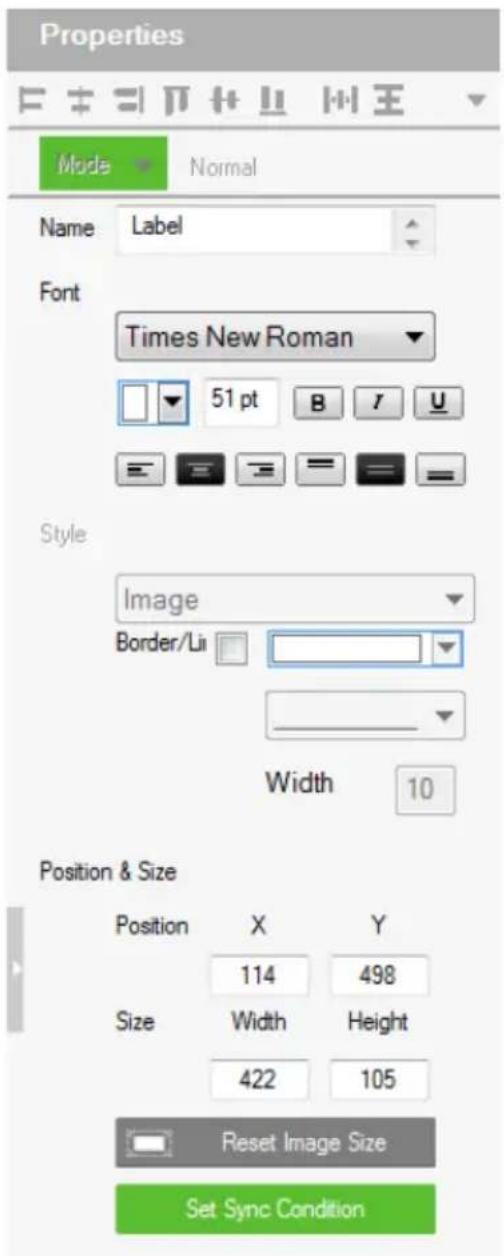
The Label properties provide settings for the displayed text and its format.
- Alignment – Aligns a group of objects. Select multiple objects for the buttons to become available:

- Name – enter the text you want to use for the label or slow double-click the label on the Edit page.
- Font – use the drop-down menu to select the font type.
- Color – use the drop-down menu to change the color of the text.
◆Size – enter a number (1-200) to set the size of the text. - Format– format text to Bold, Italic or Underline.
- Alignment – click a box to align the text Right, Center or Left; and Top, Middle or Bottom within the label box.
- Border/Line – select this option to configure the color, format, and width of the display screen border.
- Position and Size – X and Y position the label at the coordinates entered. Width and Height set the size of the label.
- Set Sync Condition – Displays the value of the selected variable in percentage or its raw form. To create variables, see Variables, page 222.
Slider Bars

Right click on a Viewer page and select Slider Bar to add a bar. A Slider Bar can control a device, link to another page, or run a macro.
Use the Mode drop-down menu to select the type of slider bar (Basic Slider Bar or Advanced Slider Bar).
Basic Slider Bar
◆A slider bar where you enter the minimum and maximum values to calculate the range and levels on a slider bar, and then add one command to configure the Basic Slider Bar's action (See Slider Value, page 172). Choose options under Value to configure the slider bar's range.
- Direction – sets the bearing of the slider bar.
- Style – click the drop-down menus to select the Foreground Color and Background Color for the slider bar.
- Value—Sets the total number of levels for the slider bar.
- ASCII / HEX – click a radio button to select the format for the slider bar values.
- Minimum – enter the lowest level on the bar.
♦Maximum – enter the highest level on the bar.
- Level – this represents the number of levels on the slider bar. You can calculate the value of each level with the formula: Maximum Value - Minimum Value / Level = Value Per Level. The Level is automatically calculated according to the Minimum and Maximum values you enter.
♦ Position and Size – depending on whether the bar is set Vertical or
Horizontal you can use either the Size: Width or Height box to enter a number to resize the length of the slider bar.
- Set Sync Condition – Automatically synchronizes the slider bar to the selected variable. To create a variable, see Variables, page 222.
Advanced Slider Bar
- A slider bar where you set the number of levels and add a command for each level in the bar (see Level, in the table, on page 166). Choose options under Value to configure the slider bar's range:
♦ Direction – sets the bearing of the slider bar. - Style – click the drop-down menus to select the Foreground Color and Background Color for the slider bar.
- Value – Sets the total number of levels for the slider bar.Level – this represents the number of levels on the slider bar. For each level you must add a separate command in the Slider Bar Action – Commands list (see Level, in the table, on page 166).
PowerPoint Control and Media Control Templates

Click a PowerPoint control template or a media control template to configure its position, size, and the PC that controls it.
- Position and Size - X and Y position the label at the coordinates entered. Width and Height set the size of the label.
- Select Device – Select the PC that stores the PowerPoint or media files using the drop-down list.
Images
The Properties for an image provide options to change and import images to the page. Images can be layered with other objects so that they can be placed as a background or as highlights for buttons (see Layering Images, page 155). You can Group, Order, Align, Make Same Size or Space Evenly from the Object menu.
Note: For imported images, make sure the file names contain English alphabets and/or numerals only.

-Style – shows the image selected. Click inside the box to import an image (*.png,*.jpg,*.jpeg,*.bmp) to the page.
- Transparency – enter a number (0-100) or use the slider-bar to set the transparency of the image selected.
♦ Position and Size – X and Y position the image at the coordinates entered. Width and Height set the size of the image.
- Reset Image Size – resets the image size.
Layering Images
Images can be layered with other objects, such as labels and buttons, so that they can be placed as a background or as highlight for the page and/or other objects.
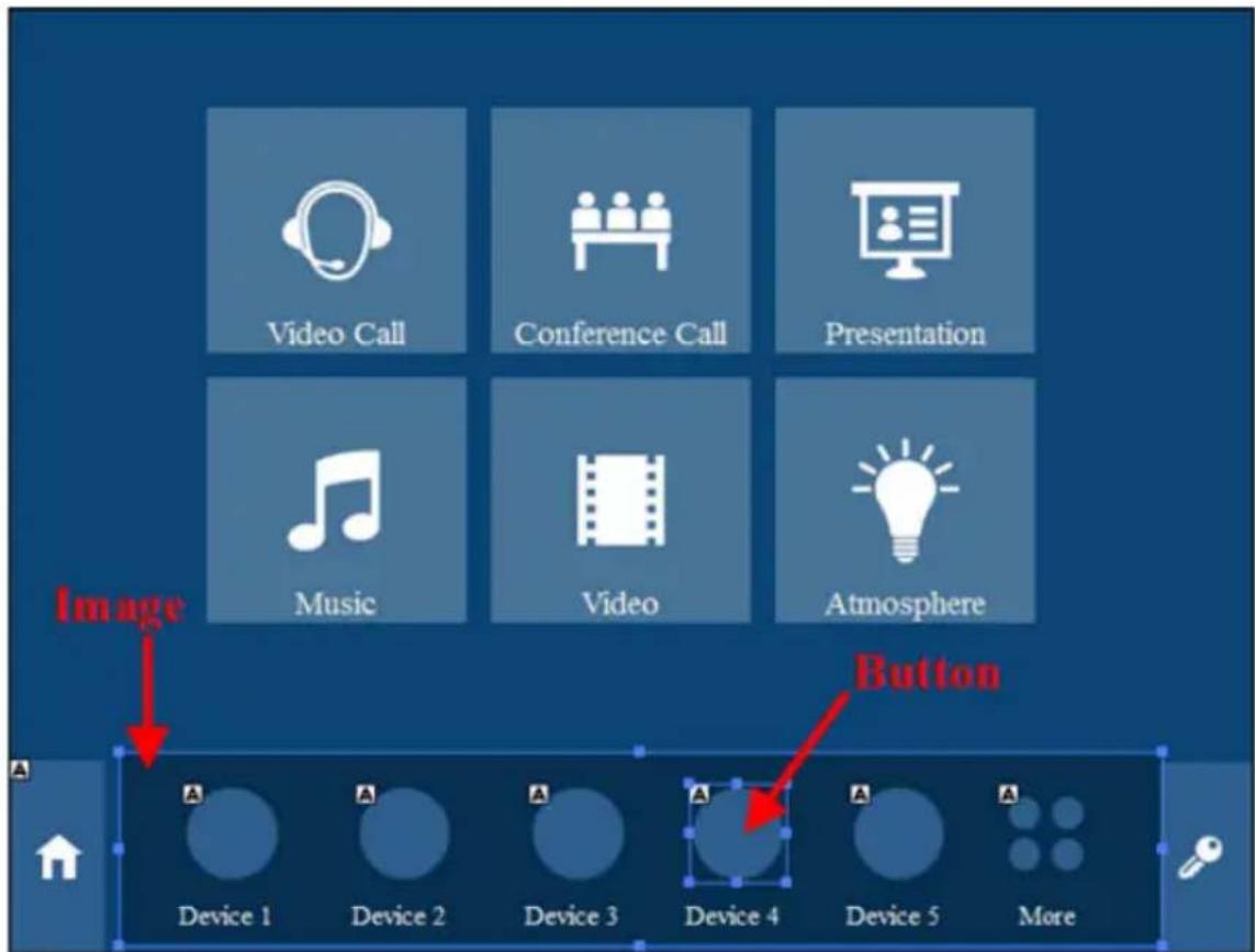
Videos
A video object is a control used for video preview, video assignment on managed displays, or video streaming by RTSP. For more details of each, see the corresponding section below:
♦ Video previews: See Setting Up a Video Preview Window, page 156.
♦ Video assignment: See Setting Up a Video Control Window, page 156.
♦ Video streaming: See Setting Up a Video Streaming Window, page 159.
Setting Up a Video Preview Window
You can set up video preview windows to view video sources from ONVIF-compliant cameras managed by the controller.
- In your project file, make sure you have added ONVIF-compliant cameras as Ethernet devices in the Device Configuration list.
- Right-click a viewer page and select Add Video.
- Click the added video object and configure the following properties.
◆ Mode: Select ONVIF.
♦ Position & Size: Configure these settings as required.
- Select Device: Select the added ONVIF-compliant camera.
Setting Up a Video Control Window
Video control windows are objects on the Viewer which allow you to see previews of video sources (on a source object) or the assigned video sources (on a display object), and to switch video sources by tapping or dragging and dropping actions from the Viewer. Note that video control window is only applicable to ATEN networked video extenders.
For example, the following Viewer contains 8 video control objects, the top 3 are video source objects, each show a preview of its connected video source, and the bottom 5 are display objects, each showing its assigned video source.

To switch a video source on a display, tap a source object and then tap a display object. The switch takes effect immediately. Alternatively, you can drag-and-drop a source object onto a display object if you have this control action enabled.
To set up a video control object, follow the steps below.
- In Configurator, you are advised to add at least one video transmitter as Ethernet device (to the Device Configuration list) for every 4 video control objects to use the as a gateway to obtain previews.
Important:
◆ Videos can only be transmitted via video transmitters to the controller.
◆ To ensure preview quality:
- Add at least one video transmitter (to the Device Configuration list) for every 4 video control objects. Adding more video control objects will likely reduce the refresh rate and smoothness of the preview.
- Avoid concurrent viewing from more than one user via the Control System App.
◆ Use the VE89 control app to preview video walls.
- To ensure stable preview delivery, it is recommended to use the windows version of the Control System App for prolonged viewing or monitoring. Prolonged viewing on iOS platforms may result in automatic termination of the process due to the platform’s protection mechanism to ensure its normal functioning.
- Right-click a Viewer page and select Add Video.
- Click the added object and configure its properties.
◆ Mode: Select VE89 Series.
♦ Position & Size: Configure these fields as required.
- Select Device: Select a video transmitter as the gateway for obtaining a preview of what is displayed on the specified extender (as configured for Port and ID).
Important: Only connect up to 4 control objects to one device.
- Port: Select the device type. Select Transmitter for a source object and Receiver for a display object,
ID: Type the device ID for the specific transmitter or receiver. Allow drag-and-drop: Select this option to allow drag-and-drop controls.
4. Click the added object and configure the action.
For example:
(a) Create a variable to store the video source on a source object.
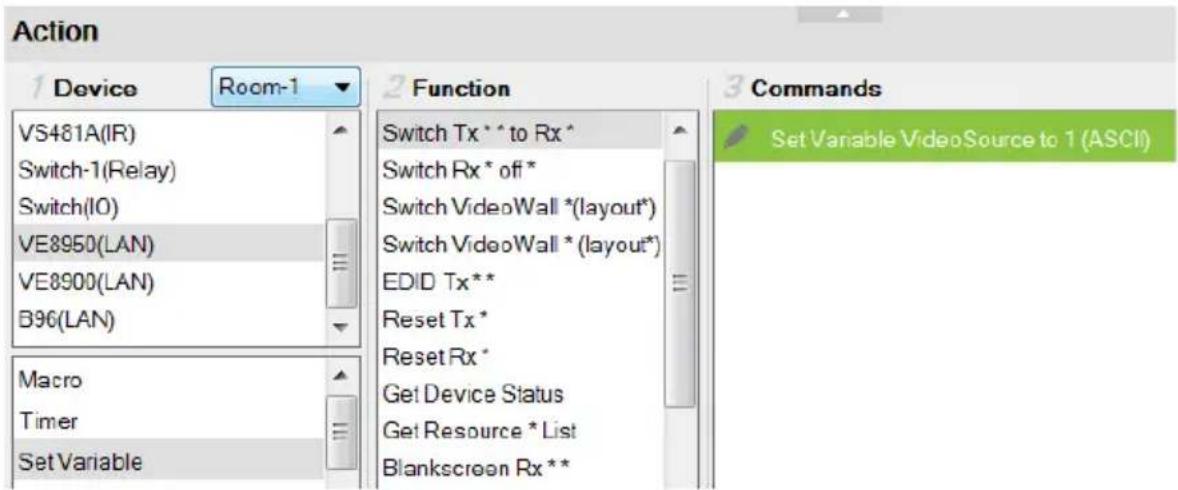
(b) Add the switching action on a display object.

For more information about creating actions, see Button / Slider Bar / Dial Kit Actions, page 166.
Note: To ensure smoothness of video transmission, prevent accessing this Viewer page from two or more devices at the same time.
Setting Up a Video Streaming Window
You can set up a window to stream video content via RTSP.
- In your project file, make sure you have added an RTSP-compliant device and configured the Stream settings.
- In a Viewer page, right-click in the blank space and select Add Video.
- Click the added video object, and configure its properties as follows.
Mode: Select RTSP.
- Position & Size: (Optional) Specify the position and size as required. Alternatively, drag any of the object corners for resizing; mouse over the object to drag-and-drop it to reposition within the Viewer page.
- Select Device: Select the added Ethernet device.
- RTSP Settings
Default: Select this option to use the typical format for the RTSP URL (rtsp://username: password@ip:port). Type the RTSP URL of the device in the blank below.
- Custom: Select this option to use a different RTSP URL format. Type the URL in the blank below.
Dial Kit
A dial kit template consists of a display screen and a set of dial keys. To configure their appearance, click on the display area or a key.

Properties for Display Screen

Properties for Dial Key
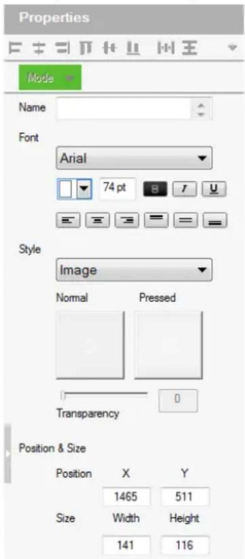
- Font – use the drop-down menu to select the font for the typed text.
- Color – use the drop-down menu to change the color of the text.
- Size – enter a number (1-200) to set the size of the text for the button.
- Format – formats text to Bold, Italic or Underline for the button.
- Alignment – click a box to align the text Right, Center or Left; and Top, Middle or Bottom within the button box.
- Style – use the drop-down menu to select the style type.
Note: The image and color settings are only applicable to dial keys.
- Image – select this option to import different images for the dial key when it is pressed and not pressed (normal).
- Transparency—enter a number (0-100) or use the slider-bar to set the transparency of the button.
- Color – select this option to use different color blocks to indicate a pressed and a normal dial key.
- Border/Line – select this option to configure the color, format, and width of the display screen border.
- Position and Size – X and Y position the button at the coordinates entered. Width and Height set the size of the button box. Click Reset Image Size to reset the button size.
Note: If you are using the Call 📋 and End Call 🌐 dials, click the dial key to configure its action. For a detailed procedure, see Example: Configuring actions of dial keys., page 173.
Frame & Line
Use frames and lines to visually group or separate control objects in your Viewer. Click a frame or line object to configure its properties.

- Style – configure the color, format, and width of the line or border of the frame.
- Rounder corder – use the scroll bar or the number box to configure the roundness of the frame corner.
◆ Fill – select this option to fill the frame with the selected color. - Position and Size – X and Y position the frame/line at the coordinates entered. Width and Height set the size of the frame/line.
Object Properties for ATEN Keypad / Control Pad
After you have added a Viewer (page 133) for your Keypad / Control, you can start configuring the Viewer. In the Viewer page, click on a button to configure its settings. The following settings appear in the Properties panel.

Mode
Use this drop-down menu to select one of the following button types.
- Normal – This is a button that stays the same when pressed.
- Toggle – for a button that switches between two images/colors to indicate the button status. This also splits the Commands list under Button Action (page 166) – to provide two commands for the button: Toggle ON and Toggle OFF.
- Press and Release – for a button that switches between two images/ colors when pressed and released. This splits the Commands list under Button Action (page 166) to provide two commands for the button: Press and Release.
- Long Press for a button that switches between two images/colors when pressed and released. This button continuously re-sends a command to a device as long as it is pressed, at the Interval specified (see Interval, below) and stops sending the command once the button is released.
Note: Use the Normal or Long Press option to set the image/color of the button based on its status.
- Name – (optional) type the text you want to use for the button (or slow double-click the button on the Viewer page).
- Font – use the drop-down menu to select the font type.
- Color – use the drop-down menu to change the color of the text.
- Size – enter a number (1-200) to set the size of the text for the button.
- Format – formats text to Bold, Italic or Underline for the button.
- Alignment – click a box to align the text Right, Center or Left; and Top, Middle or Bottom within the button box.
- Style – use the drop-down menu to select the style type.
- Image – imports an image to use as the button’s standard background and click Pressed to import an image to use when the button is pressed.
- Color – allows you to use drop-down menus to select the buttons color for Normal and Pressed.
- Transparency – enter a number (0-100) or use the slider-bar to set the transparency of the button.
- Send Command After Holding – Sets the required time for holding the button to apply the action for which the button is configured.
- Position and Size – X and Y position the button at the coordinates entered. Width and Height set the size of the button box.
- Set Sync Condition – Automatically synchronizes the button to the selected variable. To create a variable, see Variables, page 222. This option is only available for toggle buttons.
Button / Slider Bar / Dial Kit Actions
Understanding Button/Slider Bar/Dial Kit Actions
After you have added a button, slider bar, or a dial kit on your Viewer, define the actions it initiates using the Button/Slider Bar Actions panel. To access the panel, click on a button, slider bar, or dial key in the Viewer. The Button/Slider Bar Action panel appears.

The Button/Slider Bar Actions panel consists of the following elements:
| Setting Description | |
| Device Lists the added devices and the advanced functions. | |
| Room Select the room | that contains the devices the Viewer will control. Use this drop-down menu to select rooms in the KNX system and display KNX devices. The Viewer will only upload to a controller configured with the same Room name (see Left Sidebar, page 110). Select All Rooms to allow the Viewer to control all rooms. Selecting All Rooms will upload the Viewer to all controllers.The Accessible Room defines what Devices are available to configure new Actions in Button/Slider Bar Properties (see page 166). Only Devices listed under the same Room (see page 110) as the Viewer's Accessible Room will be listed for use in Button/Slider Bar Properties. |
| Function Lists the supported functions for your chosen device or advanced option. Double-click a function to add it to the Command List, which shows a sequence of tasks to be executed when specified conditions are met for the button, slider bar, or dial key. For details on functions, see Functions, page 169. | |
| Setting Description | |
| Commands Lists the | commands that initiate when the button or dial key is pressed. Device and Advanced Option functions can be added and associated in the Commands list together. Commands initiate in the order that they are added to the list. Right-click in the Commands list to use the menu selections: Move Up, Move Down, Copy, Paste, Delete, Save as Macro, or Test Tool. |
| Toggle ON / Toggle OFF or Press / Release | When the Button Mode (page 146) is set to Toggle or Press and Release, the Commands list splits to set the two c commands: Toggle ON / Press – lists the commands that initiate when the button is first pressed or pressed and held. Toggle OFF / Release – lists the commands that initiate when the button is pressed a second time (Toggle), or released (Press and Release). When the button is pressed again, Toggle ON initiates and the cycle repeats. |
 | The Level drop-down menu appears when an Advanced Slider Bar is selected on the Viewer page. The number of levels in the drop-down menu reflect the Level set in the Advanced Slider Bar's properties (page 152). Use the drop-down menu to select a level and then add a command for each of the Advanced Slider Bar's levels (see page 172 for details). |
 | Use Move up to move an action up in the Commands list, or Move down to move an action down in the Commands list. |
 | Use Delete to remove an action from the Commands list. |
 | Use Save as Macro to save the commands in the Commands list as a macro. |
 | Use Test Tool to connect to a controller and test the action(s) in the Commands list. |
You can configure a button with Device commands (On, Off, Stop, Play, etc.); as a Macro to send multiple commands to one or more devices; or as a Link to other Viewer pages. Advanced Options allow you to add conditions to the commands, as described on the next page.
Configuring Button/Slider Bar Actions
To add one or more actions to a button, slider bar, or dial key, follow the steps below.

- In the project file, click to select the button, slider bar, or dial key in the Viewer. The Button/Slider Bar Action panel appears.
- In the Button/Slider Bar Action panel, select a Room.
- Add commands.
For details on device functions and advanced functions, see Functions, page 169.
a) Click a device or an advanced option to display its supported functions.
b) Double-click a function to add it to the Commands list.
c) Repeat step 3a and 3b if you wish to initiate a sequence of actions.
- In the Commands list, double-click the commands to configure them.
Functions
Button/slider bar functions can be understood as device functions and advanced functions.
- Device functions – These are functions that the selected controller or a device managed by the controller initiates. The supported device functions vary depending on the device you select in the Device list, as illustrated below. For details on controller functions, see Device Functions, page 171. Controller functions

VM3404H functions

- Advanced functions – These are functions that involve more than one devices in the project. Use the indicated column to select an advanced function, the available options are listed in the Function list. For details about each advanced function, see Advanced Functions, page 174.

Device Functions
◆ Each ATEN controller supports the following functions.
- Delay – adds a delay in seconds. Enter a number between 0.1-180.
- Relay – adds an Open, Close, Toggle or Pulse action on the selected controller and Relay port.
- DO – adds an Open, Close, Toggle or Pulse action on the selected controller and Digital Output port.
- Wake on LAN – powers on the specified computer (MAC address) over Ethernet.
- Serial Raw (ASCII) – adds a serial command in the ASCII mode.
- Serial Raw (HEX) – adds a serial command in the HEX mode.
- Telnet Raw (ASCII) – adds a telnet command in the ASCII mode.
- TCP Raw (ASCII) – adds a TCP command in the ASCII mode.
- TCP Raw (HEX) – adds a TCP command in the HEX mode.
♦ UDP Raw (ASCII) – adds a UDP command in the ASCII mode.
◆ UDP Raw (HEX) – adds a UDP command in the HEX mode.
- HTTP – adds an HTTP command.
- HTTPS – adds an HTTPS command.
- Pronto Hex Code – adds an IR command using Pronto Hex codes.
- Value Types
When a device command has multiple values you can double-click it and use the Show Flag Menu* to select a device setting:

- Library Value – use the drop-down menu to select a device setting for the command. The selection of settings in the drop-down menu can be modified using the Database Generator to edit the command string (see Editing / Adding a New Device, page 256).
Flag2 Flag Variable – clicking this button allows a Flag with a set of values to be selected for the action. The button’s action will select a setting according to the Flag value. Each value in a Flag can be set to a different device using a Set Flag (as a button to select
the device). When that (Set Flag) button is pressed, the Flag value is set for that particular device, and will be used as the setting for this action, when it's button is pressed.
Volume Variables – Select this option to use a Variable in the command. After selecting the option, a drop-down menu containing a list of the Variables that you created appear.
Slider Value Slider Value – select this option to configure a Basic Slider Bar's command. The range and change levels are automatically configured according to the minimum and maximum values set for the Basic Slider Bar. This option only appears when a Basic Slider Bar is selected on the Viewer page and you are adding Slider Bar Action commands.
Note: The Show Flag Menu allows you to use a single Flag for all devices rather than adding a Conditional Flag for each device.
- Dial Value Dial Value – select this option to use the string of values that has been dialed using the dial kit via Viewer from a mobile device.
Level 1 Level – When an Advanced Slider Bar is selected on a Viewer page, the Level drop-down menu appears above the Commands list. A command must be added to each level of an Advanced Slider Bar. To configure each level, use the drop-down menu to select a level and then add a command to it.

Applications of Device Functions
Example: Configuring actions of dial keys.
Out of the 15 keys on a dial kit, only the Call and End Call keys require configuration, the actions for other keys are pre-configured to send out the number or character as indicated on the keys.

Follow the steps below to add an action to the Call key.
- Click the Call key in the Viewer to display the Button Action panel.
- Select a device (e.g. a video conferencing system) and double-click to add a function for the key. In this case, it should be a dialing function.

- Double-click the added command and select Dial Value.

Advanced Functions
Use advanced options for button和社会 actions that involve a series of actions (Macro), actions that the involve page redirect (Link), or actions that involve change or update of device settings of multiple objects (Set Variable).
Note: Associate Set Flag, Condition, Change Button State, or Change Label commands with device commands in the Commands list by dragging and dropping them into a tree view list, which allows them to initiate together (see Applications of Advanced Functions, page 176).
- Macro – sends multiple commands to one or more devices. Select to add a macro command from the Function list. To create a macro, add multiple device actions to the Commands list, then click the Save as Macro icon or access the function by clicking the Library icon (page 98).
-
Link – a command used on a button to:
-
redirect a Viewer Page to another Page when the button is pressed, for example, a Home page button, which redirects the display to the home page.
- redirect one or more Viewers to a specified Page when the button is pressed. For example, when an Exit button is pressed, you can have all Viewers (used by touch panels and/or mobile devices in one meeting room) return to their home page.
◆ Configure the following fields for the command:

- Link To: Select a destination page
- Myself/Mirror: Select Myself to have the Viewer link to a selected page only on the tapped device; select Mirror to have all the devices that use the same Viewer file to return to the selected page.
For more information on configuring a button, see Configuring Button/Slider Bar Actions, page 168.
- Set Variable – creates a variable to represent a device setting (e.g. speaker volume) that can be used by two or more control objects (e.g. slider bar or buttons) in the Viewer. This function is used when you have more than one Viewer objects controlling the same device.
Note: To complete this setting, go to Properties of the control objects and configure the Set Sync Conditions setting.
- Set Flag – sets a flag value to represent the new device status when a command changes a device setting. Set Flags are added to the Commands list after device commands to change the Flag (device status).
- Condition – adds one or more conditions that must be met for commands to initiate. The conditions can be based on a Variable or a feedback value (setting value sent from a managed device).
- Variable conditions— Use Variable conditions for the controller to carry out actions (commands) when the specified Variable meets the specified conditions. Use Variable If, Variable Else If, and/or Variable Else to fully cover all scenarios in your application. For example, if you want a display a warning message on the Viewer when the volume of a speaker is at its maximum (10 dB), you will need to: (a) Set up a Variable for the speaker volume; (b) Select a Variable If condition; (c) Double-click the condition to set the Variable value to 10; (d) Drag a Change Label command and nest it under the condition you selected in step (a); (e) Double-click the Change Label command to type the warning message you wish to display when the speaker volume reaches 10 db.
- Feedback conditions – Use feedback conditions for the controller to carry out actions (commands) when the specified feedback value meets the specified conditions. Use Feedback If, Feedback Else If, and/or Feedback Else to fully cover all scenarios in your application.
Note: The Else If and Else conditions can only be nested under the If conditions and can not be used on their own.
- Change Button State – this command changes the image of another button when this button is pressed – allowing the image of any other button to change when the command from this button is sent. Change Button State is added to the end of the Commands lists. When adding this to a Toggle button it allows the image to switch with the toggle behavior: Normal or Pressed. In this situation the Change Button State is added to the end of both the Toggle ON and Toggle OFF Commands lists.
- Change Label – this option changes a label’s text with text that you enter manually or with text from a device’s return message. A Manual Change Label can be added to the beginning or end and with a Condition in the Commands list. Adding it to a Condition guarantees the label only changes when the command initiates.
- Change Group Button State – this option adds a command that changes the button selected in a Radio Group (page 103). Create a Radio Group
and then a Function will be listed for it when Change Group Button State is selected. Add the Change Group Button State to the Commands list of a button and use the drop-down menu to select the button in the Radio Group you want selected.
- Change Slider Bar Level – this option adds a command that changes the level of a Slider Bar. Create a Slider Bar and then a Function will be listed for it when Change Slider Bar Level is selected. Add the Change Slider Bar Level to the Commands list of a button and use the drop-down menus to select the Slider Bar and Level to change.
- Change Button Name – this option adds a command that displays specified text on another button when this button is tapped. A typical application of this command is when you want to show the assigned source on an output device as soon as the source is switched.
- Function – lists the commands that can be added to the Commands list. Select an option under Device, then double-click or drag & drop commands from the Function list to add them to the Commands list.
Applications of Advanced Functions
Advanced Options allow you to include conditions with commands in the Commands list. Associate Set Flag, Condition, Change Button State or Change Label functions with a command in the Commands list by dragging and dropping them into a tree view listed with the command, so that they initiate in the order listed.
Set Flag
Adds a Set Flag to change a Flag's value when a command changes a device setting. This sets the Flag value to match the new device setting (e.g. ON or OFF). Always add a Set Flag to a Condition Flag, after the device action(s):

To add a Set Flag:
- Under Device, select Set Flag.
-
From the Function list, select the Flag.
-
From the Function list, drag and drop the Flag to add it to the end of the Condition Flag, in a tree view list:
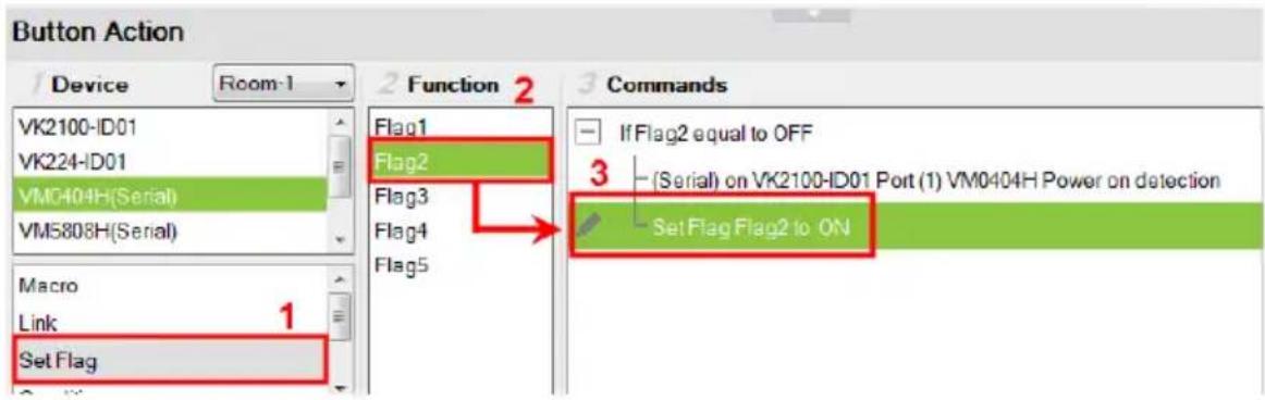
- Double-click Set Flag in the Commands list to use the drop-down menus to set the Flag and Value.

Condition
Adds a condition that must be met before the commands listed with it can initiate. When the button is pressed, the Condition's set value must equal the Flag or Feedback value for the command(s) to initiate. There are two condition types: Flag and Feedback.
- Flag – Adds a condition based on a Flag’s value. “If Flag equals Value” is true, the condition is met and the commands listed with the Condition will initiate. Always add a Condition Flag at the top of the Commands list, drag and drop the device command(s) and then a Set Flag at the end, in a tree view list:

To add a Condition Flag:
- Under Device, click Condition.
-
From the Function list, select Flag.
-
Double-click Flag to add the Condition Flag to the Commands list.

- Double-click the Condition Flag in the Commands list to use the dropdown menus to set the Flag and Value.

- From the Function list, drag & drop device commands to add them to the Condition Flag, in a tree view list:

- Add a Set Flag after the last device command in the Commands list:
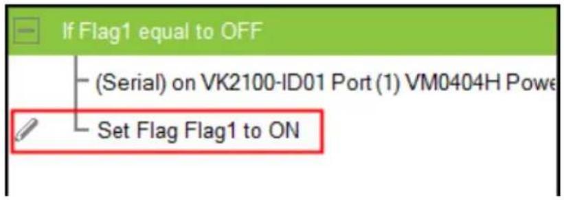
- Feedback – adds a condition based on the text from a serial/telnet/TCP device's return message. Always add a Condition Feedback to a serial/
telnet/TCP command, with command(s) added below the Condition Feedback, in a tree view list:
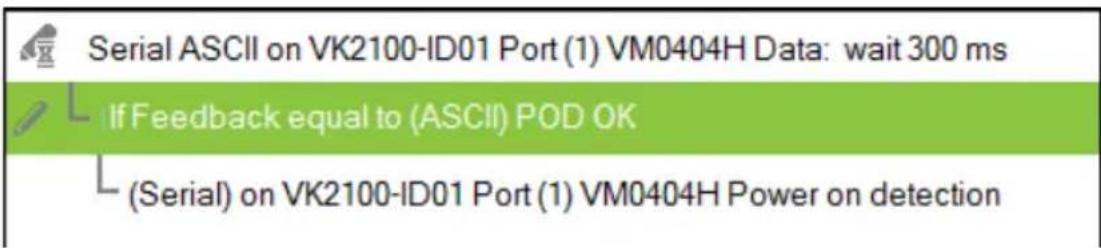
Receive Time – when a Feedback condition is added to a device command the wait to Receive Time drop-down menu appears allowing you to set the amount of time to wait before it stops receiving the return message from the device.
There are three Condition Feedback types:
- Equal – when the text sent from a serial/telnet/TCP device’s return message matches all of the text entered for a Condition Feedback Equals, the commands listed below it will initiate.
- Include – when the text sent from a serial/telnet/TCP device’s return message matches part of the text entered for a Condition Feedback Include, the commands listed below it will initiate.
- Bypass – this option bypasses matching text from the serial/telnet/TCP return message and initiates a Change Label command. The label’s text will change to the return message sent from the device (i.e. the Feedback Result). A Change Label must be added to the Feedback Bypass for it to work.
To add a Condition Feedback Equal/Include:
- Under Device, click Condition.
-
From the Function list, select Feedback.
-
From the Function list, drag and drop Feedback to add it to the Serial/Telnet/TCP command, in a tree view list:

- Double-click If Feedback equals to in the Commands list and use the drop-down menu to select equal to or include and enter the Text.

Text entered here must match all (equal to) or part (include) of the text from a serial/telnet/TCP device's return message for the command(s) to initiate. Use the ASCII / HEX drop-down menu to select the format.
- From the Function list, drag & drop device command(s) to add them to the Feedback Equal/Include Condition, in a tree view list:

To add a Feedback Bypass Condition with Change Label:
- Under Device, click Condition.
-
Select Feedback from the Function list.
-
From the Function list, drag and drop Feedback to add it to the Serial/Telnet/TCP command, in a tree view list:
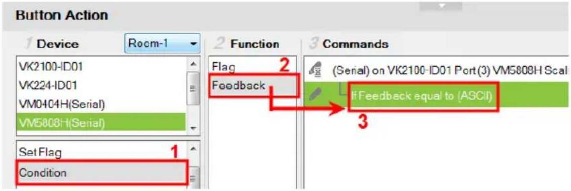
- Double-click If Feedback equals to in the Commands list and use the drop-down menu to select bypass.

-
Under Device, select Change Label.
-
From the Function list, select the Viewer Page where the label is located.
-
From the Function list, drag and drop the Viewer Page to add it to the Feedback Bypass Condition, in a tree view list:

- Double-click Change Label in the Commands list and use the dropdown menu to select a label. Labels are identified by object IDs (see page 144).
- Change Label Video wall - Video Wall_274 to FEEDBACK_RESULT
The label's text will change to the serial/telnet/TCP device's return message.
Change Button State
This option is used to change another buttons image when this button is pressed – allowing the button image to switch depending on the status: Normal or Pressed. Change Button State is added to the end of the Commands lists and should point to a Toggle button. Adding this to a Toggle button allows the image to switch with the toggle behavior: Normal or Pressed.
To add a Change Button State:

- Under Properties, use the Mode drop-down menu to select a button type.
- Under Style, click the Normal and Pressed button to select an image/color* for the button's state.
Note: Use the Style drop-down menu to select Image to import an image file for the button state, or Color to choose a color format for the button state.
- Add the Toggle ON and Toggle OFF device commands to the Commands lists.
-
Under Device, select Change Button State.
-
In the Function list, select the Viewer page.
- Select the Toggle ON radio button, then in the Function list, double-click the Viewer page to add it to the end of the Toggle ON commands in the Commands list.
- Select the Toggle OFF radio button, then in the Function list, double-click the Viewer page to add it to the end of the Toggle OFF commands in the Commands list.
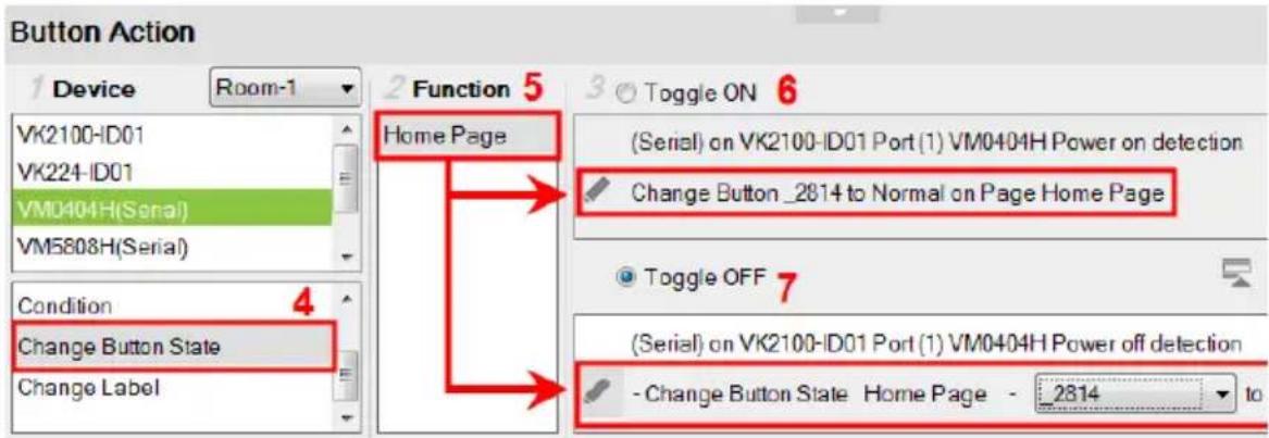
- In each Commands list, double-click the Change Button State command to set the Button and State (Normal or Pressed).

Change Label
Changes a label's text with text that you enter manually or with text from a serial/telnet/TCP device's return message (Feedback Result). A Change Label that uses a return message, must be added to a Feedback Bypass Condition (page 181). A Manual Change Label can be added anywhere in the Commands list. Adding it to a Condition guarantees the label changes only when the command initiates.
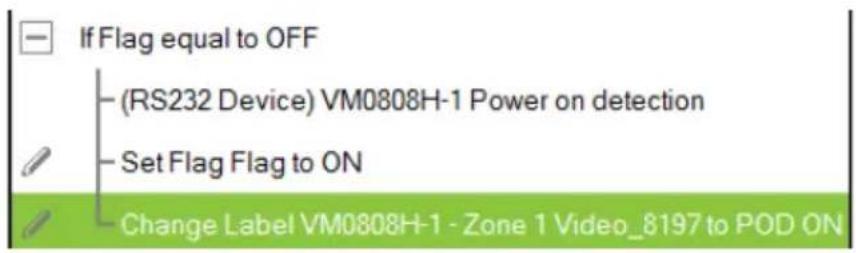
To add a Manual Change Label:
- Under Device, click Change Label.
- In the Function list, select the Viewer page where the label is located.
- Double-click or drag and drop the Viewer page to add the Change Label to the Commands list.

-
Add a Change Label to multiple or Toggle ON / Toggle OFF Command lists to have the same label change text for different actions.
-
In the Commands list, double-click Change Label to use the drop-down menu to select a Label and input the Text. This is the text in the label that will appear when the button is pushed.

Repeat the steps to add a Change Label for the reverse action (i.g., On and Off).
Change Group Button State
Adds a command that changes the selection in a Radio Group (see page 103). To use this function, first create a Radio Group and then add a button to the Viewer page. Add a Change Group Button State independently or with a device command:
To add a Change Group Button State:
- Under Device, select Change Group Button State.
- From the Function list, select the Viewer Page where the Radio Group is located.
- From the Function list, drag and drop the Viewer Page to add it to the Commands list:

- Double-click Change Group Button in the Commands list and use the drop-down menu to select the Button.
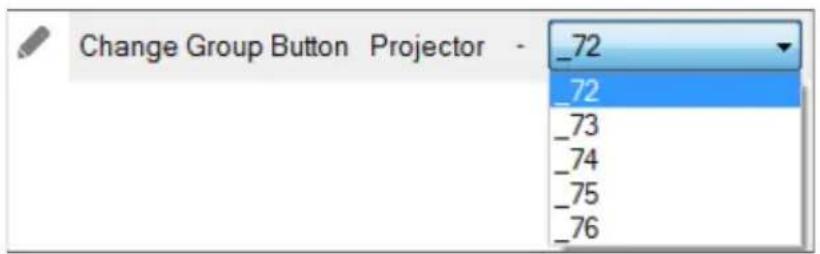
Change Slider Bar Level
Adds a command that changes the level of a Slider Bar. To use this function, first create a Slider Bar on a Viewer page. Add a Change Slider Bar Level independently or with a device command.
To add a Change Slider Bar Level:
- Under Device, select Change Slider Bar Level.
- From the Function list, select the Viewer Page where the Slider Bar is located.
- From the Function list, drag and drop the Viewer Page to add it to the Commands list:
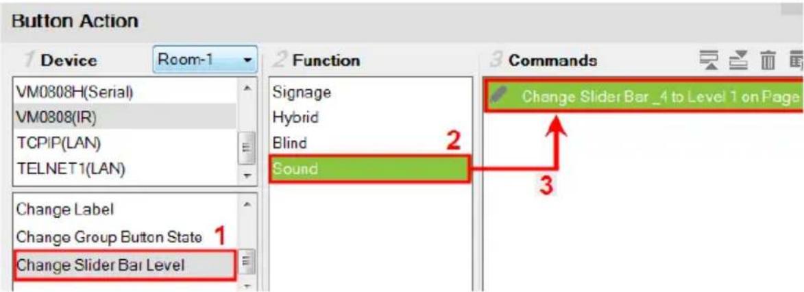
- Double-click Change Slider Bar in the Commands list and use the dropdown menus to select the Slider Bar and Level.

Change Button Name
The Change Button Name command is used to display specified text on a selected button when the configured button is tapped. An application of this command is indicating the assigned source for a display device on a Viewer as soon as the source is assigned. This way, you can keep track of the source that is currently showing on a particular display device.
Example:
- Indicate the currently assigned source on a display device (in the Viewer).
- Assume an environment consisting of one monitor and five sources buttons (computer, laptop, camera...etc.), as illustrated below, and that when a source button is tapped, the source will be immediately assigned to the display.
Configuration goal: To have the assigned source printing on the display button (on the Viewer page), configure each source button so that when it is tapped, the following actions (commands) initiate: (1) Display the source to the display; (2) Print the name of the assigned source onto the display device.

- Click a source button to display the Button Action panel.
- In the Button Action panel, select Change Button Name.
- From the Function list, double-click the Viewer page where the source button is located. In this example, double-click the Video Wall option. The Change Button Name command is added.
-
From the Commands list, double-click the Change Button Name command and configure the following.
-
Select the ID of the display button to indicate the location of print the text. In this example, it is the video wall's ID.
-
Type the text you wish to show when the source button is tapped. In this example, enter “PC”.
-
Follow steps 1 to 4 to configure each of the source buttons.
Library
The Library icon on the Project bar offers the following functions. The table below provides an overview of each function.
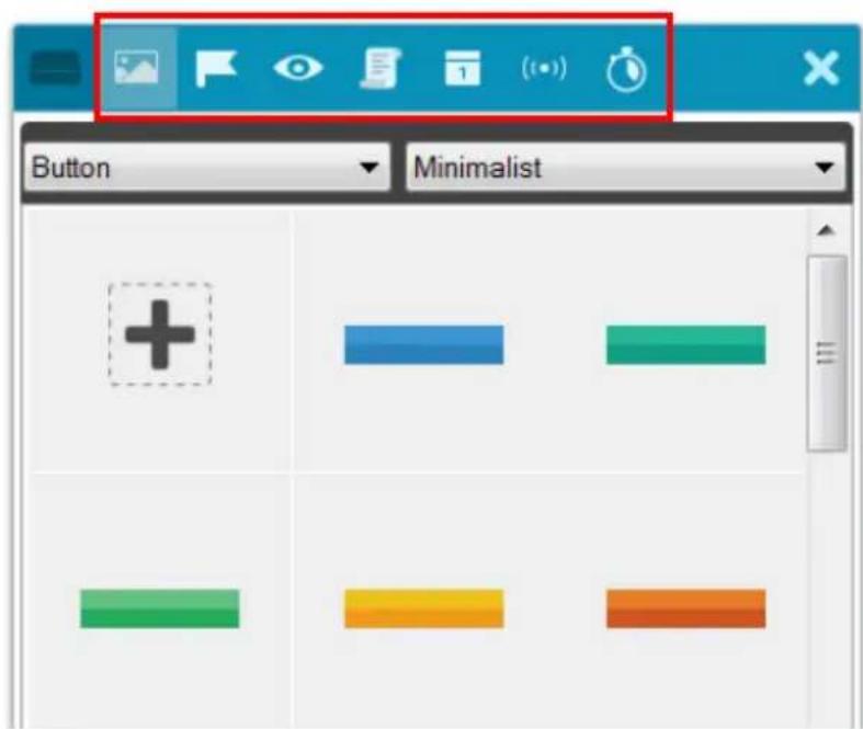
| Control Description | ||
 | Graphic Library | Find graphic templates such as backgrounds, buttons, device icons, and control interfaces for your viewer. For details, see Graphic Library, page 191. |
 | Flag Flags are created to include parameters when settings are changed to indicate the current status. For details, see Flag, page 194. | |
 | Monitor Monitors allow you to set Conditions for Digital Input (dry contact) and Digital Input (VDC) signals and Flags on a port that will initiate an Action. In addition, you can create Listen to port and Query port monitors which check a device's status to initiate actions. For details, see Monitor, page 196. | |
 | Macro Macros initiate a sequence of actions on one or more hardware devices. For details, see Macro, page 218. | |
 | Schedule | Click to create scheduled events. For details, see Scheduled Events, page 220. |
| Control Description | |
 | Variables Creates a Variable for a device setting (e.g. volume) that is controlled by two or more objects (e.g. slider bar or buttons) on the Viewer. When the device setting is changed through one of the objects, its setting is automatically synced and reflected on all the objects. For details, see Variables, page 222. |
 | Timer A timer event is a device action that initiates as soon as the defined countdown time is up. The advantage of using a timer event, as opposed to a combination of delay command and device command, is that it saves time by executing the defined action while other actions (commands) within the series execute. For more details, see Timers, page 231. |

Graphic Library
The Library icon on the Project bar provides a Graphics tab and dropdown menus with ready-to-use graphics for backgrounds, buttons, icons and device interfaces. Device Interface provides entire page layouts that you can use as templates for different types of devices. Double-click or drag and drop graphics to add them to the page. Images can be imported for icons and buttons in various formats (*.png,*.jpg,*.jpeg,*.bmp).
Button

Background

Image (Device Icon)

Device Interface
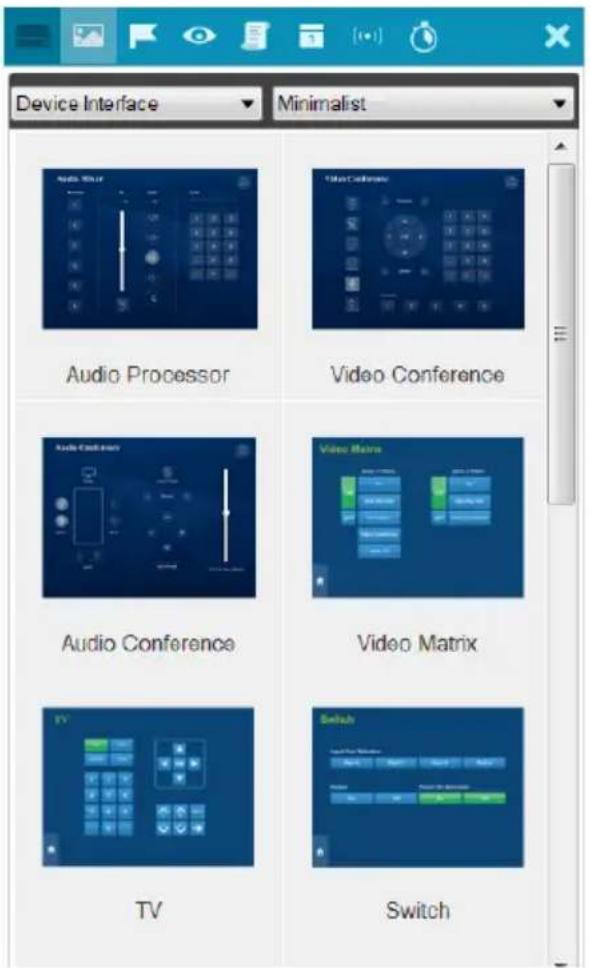

Flag
Flags are created for control buttons to include parameters for when settings are changed or requests are made to change settings on a device. Flags indicate what the status is and what action to take according to the value. Flags are added as actions to Button Properties as a Condition or Set Flag value.
Conditions tell a button to initiate associated actions if the flag value is true: "If Flag equals Value" initiate the action. Actions are associated with a condition so that they only initiate if the flag value is correct. That way an ON command is only sent to a device if the current flag value is OFF.
Set Flag changes the flag value when a device setting has changed. So that if a device is OFF and the action turns the device ON, adding a “Set Flag 1 to ON” will change the flag value to ON. Now the flag’s value matches the device status so that actions associated with flag Conditions will initiate accordingly.
Create flags for a device and add them as a Condition and Set Flag value in the Action – Button Properties (see Button / Slider Bar / Dial Kit Actions, page 166).
To create a Flag:
- Select Flag and click + Create New . The New Flag menu appears.

-
Enter a Name and select a radio button to set the flag value.
-
Select On/Off and use the drop-down menu to select the Default Value.
-
Enter a range (1-100) for the values in the two boxes and use the drop-down menu to select the Default Value. Use the drop-down menu to select the format ASCII or HEX.
-
Click to create more flags or double-click a flag to edit it. The flags will appear in the list, as shown below.

- Name – Lists the Flag names which have been created.
- Value – Lists the flag's values or range of values.
- Default – Lists the flag’s default value.
-
X – Deletes a flag from the list.
-
Select Condition or Set Flag to add flags as a command in Button Action by selecting a button on a Viewer page (see Button / Slider Bar / Dial Kit Actions, page 166).

Monitor
Understanding Monitor
A Monitor allows you to set conditions on a port using Digital Input (VDC) and Digital Input (Dry Contact) signals, return messages, and Flags. When the condition is met, the controller will initiate the desired action. Digital Input (VDC) hardware devices provide voltage signals between 1 and 24. Digital Input (Dry Contact) hardware devices provide open and closed circuit signals. Hardware devices with return messages can be monitored using Listen to port or Query port conditions via text they transmit. These signals provide indicators from sensors or switches of an event. An event can be the temperature, power, dry contact, sensor, switch status, or message from a device. There are two parts to a monitor, the Condition and Action.
Monitor Page Options
There different types of monitors you can create to fulfill different scenarios. A monitor (as illustrated below) contain the following configuration fields:

| Control Description | |
| Type Use this drop | -down list to select a monitor type:If – select this option for a single condition monitor. “If” the single condition is met, the action initiates. For details, see Creating an If Monitor, page 202.Switch– select this option for multiple conditions that use more than one “If” conditions for the monitor. In this type, if one of the conditions is met, the monitor will initiate the action. For details, see Creating a Switch Monitor, page 205.Bypass– select this option to transmit device feedback message to the selected variable actively listening for a message or by receiving a return message from the specified devices. For details, see Creating a Bypass Monitor, page 209.While Loop– select this option to execute the specified actions at the defined frequency (Query Frequency). For details, see Creating a While Loop Monitor, page 211.Professional– select this option to create variables and load values into these variables using programming script. For details, see Creating a Professional Monitor, page 212. |
| Name Enter a name | for the monitor. |
| Query Frequency | Use this drop-down menu to select how frequently the monitor checks a device for a signal. |
| Condition Use this | section to add one or more conditions that will need to be met for the Action to initiate. You can create up to 32 conditions for each monitor. For details, see Condition Types, page 198. |
| Action Use this section | to create the commands that will initiate when the monitor's conditions are met. For details, see Device Functions, page 171 and Advanced Functions, page 174. |
 | Click to hide or display the Device and Status/Function columns in the Condition and Action lists so that you can see a complete row of Conditions/Commands. |
 | Click to move an selected command up or down in the Commands list. |
 | Click to remove an selected command from the Commands list. |
Condition Types
Note that you can create up to 32 conditions for each monitor.
- Listen to port / Query port
- (Query port only) Click F(x) to open the drop-down menu to select a device command to send out; or enter a command string; and then the click Edit Return Message icon and do as explained below.

- Edit Return Message
(Listen to port / Query port) Next configure the parameters for the return message from the device. This message must match for the condition to be met. In the Condition list double-click the command and then click to open the Edit Return Message window:
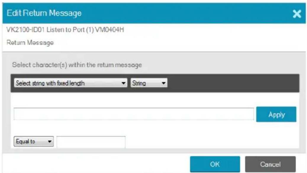
Use the drop-down menu and enter a string of that will represent the characters in a return message from the serial device:
- Select string with fixed length

Use this to set a string of characters that are set within a fixed parameter. Enter a string of characters and use the S to set the start of the string and E to set the end and then click Apply. The return message will need to fit the fixed string of characters set in the text box next to the Drop-Down Menu (see next page) for the monitor to be triggered.
- Select string with a non-fixed length

Use this to set a string of characters where the parameters are variable. Enter a string of characters and use the S to set the start of the string and E to set the end and then click Apply. The return message will need to fit the fixed string of characters set in the text box next to the Drop-Down Menu (see below) for the monitor to be triggered.
- Drop-Down Menu

Above, enter characters that the Select string with fixed length or Select string with non-fixed length string must match and how they must be matched: Equal to, Not equal to, Include, or Exclude for the condition to be triggered.
- Flag
Creates a flag condition for the monitor. Use the drop-down menus to set a format (how the flag value must be matched) and the flag value for the condition to be triggered.

I/O Input
Create a trigger signal from a device according to the voltage. Only device with a Digital Input (dry contract) or Digital Input (VDC) port appear in the Status list. Double-click a device in the Status list to add it to the
Condition list. Double-click the command in the Condition list to configure the setting:

The High or Low status tells the Monitor to initiate an Action when the device signal is above or below the threshold setting* for the port:
Digital Input (VDC)
- High - states that when the voltage signal is above the Upper Threshold to initiate the Action.
- Low - states that when the voltage signal is below the Lower Threshold to initiate the Action.
Digital Input (Dry Contact)
According to an open or closed circuit status for the port:
- Open - states that when the circuit is Open to initiate the Action.
◆ Closed - states that when the circuit is Closed to initiate the Action.
Functions
- Delay – adds a delay in seconds. Enter a number between 0.1-180.
- Relay – adds an Open, Close, Toggle or Pulse action on the selected controller and Relay port.
- DO – adds an Open, Close, Toggle or Pulse action on the selected controller and Digital Output port.
- Wake on LAN – powers on the specified computer (MAC address) over Ethernet.
- Serial Raw (ASCII) – adds a serial command in the ASCII mode.
- Serial Raw (HEX) – adds a serial command in the HEX mode.
- Telnet Raw (ASCII) – adds a telnet command in the ASCII mode.
- TCP Raw (ASCII) – adds a TCP command in the ASCII mode.
- TCP Raw (HEX) – adds a TCP command in the HEX mode.
- UDP Raw (ASCII) – adds a UDP command in the ASCII mode.
- UDP Raw (HEX) – adds a UDP command in the HEX mode.
- HTTP – adds an HTTP command.
- HTTPS – adds an HTTPS command.
- TCP Feedback Raw (ASCII) – adds a feedback in ASCII format to having received a monitored input from a TCP client device.
- TCP Feedback Raw (HEX) – adds a feedback in HEX format to having received a monitored input from a TCP client device.
Creating an If Monitor
To create a monitor for a device port with a Condition that initiates an Action, do the following.
-
In the Design tab, click Library 📄 and click Monitor 📷.
-
Select a controller to which you want to create the monitor.
- Click
- Select If from the drop-down menu and enter a name for the monitor.
- Use the drop-down menu to set the Query Frequency.
- Select All Conditions or Any Conditions.
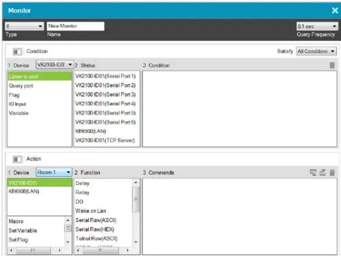
These options are only for advanced setups that require multiple events from hardware devices connected to multiple conditions. Most devices only require one signal Status added to the Condition List to initiate an Action. Most installations will not need to use this option, therefore it can be ignored.
- All Conditions: Add multiple conditions – all of which must be met for the Action to initiate.
-
Any Conditions: Add multiple conditions – one of which must be met for the Action to initiate.
-
Under Device, select a Controller from the drop-down menu, and then choose one of the following monitor types. For details, see Condition Types, page 198.
-
Listen to port – to create a monitor that actively listens for a message from the device. Under Status, double-click a device port to add it to the Condition list.
- Query port – to create a monitor that sends out a command to the device until a feedback message is received from the device.
- Flag – to create a flag condition for the monitor.
-
I/O Input – to create a trigger signal from a device according to the voltage.
-
Under Status, double-click to add a device port or flag to the Condition list. Then double-click the device port or flag in the Condition list to configure the condition settings.
Note: To set the controller as a TCP server, use the TCP Server option in the Status column, and make sure to type a TCP server port in the controller's properties settings (page 116).
-
(Optional) Use the Operator option to add additional High or Low conditions (see step 4, page 203).
-
Go to the Action section at the bottom of the page to select the hardware Device and add the Function to the Commands list, as explain in the steps that follow.

Note: For more information about Functions, see Button / Slider Bar / Dial Kit Actions, page 166.
a) First select the hardware under Devices.

b) Under Function, double-click a command to add it to the Commands list. This Command initiates when the Condition is met. For details on Functions and Commands, see Device Functions, page 171 and Advanced Functions, page 174.
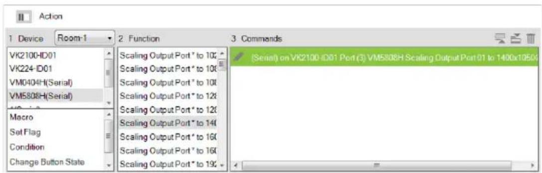
Note: If you have configured the controller as a TCP server, add TCP Feedback Raw (ASCII) or TCP Feedback Raw (HEX) command to provide feedback to the TCP client.
Creating a Switch Monitor
- In the Design tab, click Library 📄 and click Monitor 📷.
- Select a controller to which you want to create the monitor.

- Click

- Select Switch from the drop-down menu and enter a name for the monitor.
- Use the drop-down menu to set the Query Frequency.
- Use the options to create multiple condition comparisons, as explained below.
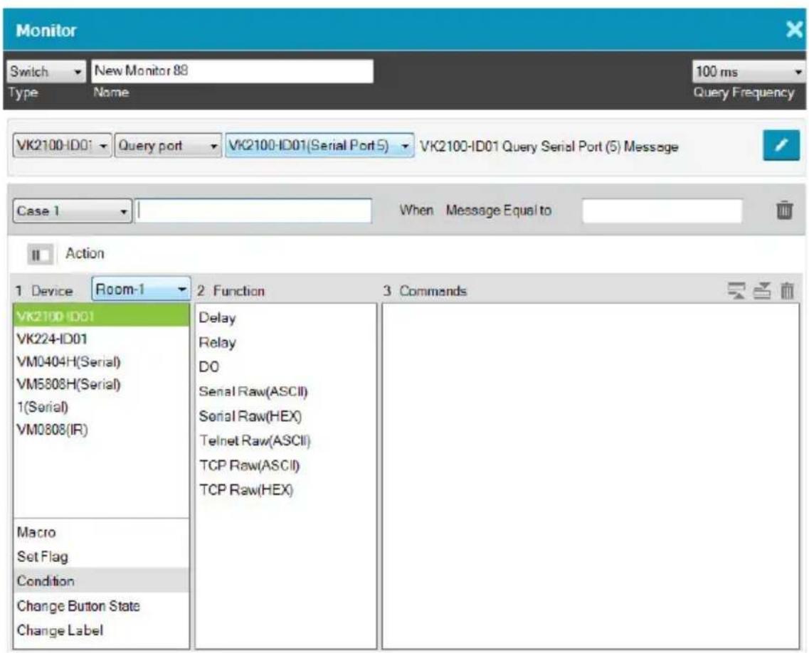
| Control Description | |
| Type Use the drop-down menu to select:If – select this option for a single condition comparison monitor.Switch– select this option for multi-condition comparisons that use multiple “If” comparisons for the command. | |
| Name Enter a unique name for the monitor. | |
| Query Frequency Use this drop-down menu to select how frequently the monitor checks a device for a signal. Options are: 100 ms - 1 second. | |
| Drop-Down Menus Under the Type drop-down menu are four addition drop-down menus used to configure the Switch Condition:Controller– use the first drop-down to menu select the controller for a Switch condition.Listen to port / Query port– use the second drop-down menu to select the condition type for a Switch condition (see step 4, page 203 for details).Serial Device PortUse the third drop-down menu to select a serial device port and configure Edit Return Message (to configure, see Edit Return Message, page 198).To set the controller as a TCP server, use the TCP Server option in the Status column, and make sure to type a TCP server port in the controller’s properties settings (page 116).Case– use the fourth drop-down menu to add cases by selecting Add More Cases for comparison that need to be met before monitor’s condition will initiate. In the left text box enter a name for the Case, in the right text box enter the character string that the return message should match. | |
| Action | Use this section to create commands for the monitor. See Button /Slider Bar / Dial Kit Actions, page 166, for details on configuring commands. |
| Click this icon to switch to the Action list view so that you can see a complete row of the command’s functions. This is a toggle button. | |
| x Closes the Monitor window. | |
- Go to the Action section at the bottom of the page to select the hardware Device and add the Function to the Commands list, as explain in the steps that follow.

Note: For more information about Functions, see Button / Slider Bar / Dial Kit Actions, page 166.
- First select the hardware under Devices.

- Under Function, double-click a command to add it to the Commands list. This is the Command that initiates when the Condition is met. For details on what each function does, see Device Functions, page 171 and Advanced Functions, page 174.
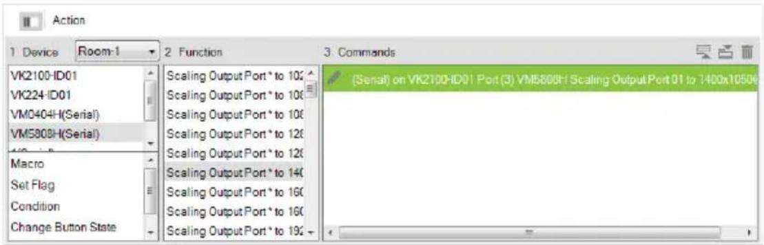
Note: If you have configured the controller as a TCP server, add TCP Feedback Raw (ASCII) or TCP Feedback Raw (HEX) command to provide feedback to the TCP client.
- You can also add a Macro, Link, Set Flag or Monitor's Condition.
- After adding all the functions to the Commands list, the Switch monitor is complete.
Creating a Bypass Monitor
Follow the steps below to create a bypass monitor.
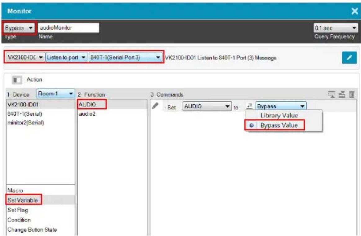
-
In the Design tab, click Library 📄 and click Monitor 📷.
-
Select a controller to which you want to create the monitor.
- Click
-
Select Bypass from the drop-down menu and enter a name for the monitor.
-
Configure the following settings.
-
Query frequency: sets how frequently the monitor checks the device for a signal. Valid values range from 100 ms to 1 second.
In the second drop-down list, select one of the following:
- Listen to port: actively listens for a message from the specified device.
- Query port: when a setting is changed on the specified device, the device sends a feedback message to the controller, informing the latest setting.
In the last drop-down list, select the port or the device to be monitored.
- Configure the actions.
a) Select Set Variable.
b) Double-click the variable you wish to update when controller detects a change for the specified device setting.
c) For a variable, double-click the command and select Bypass.

Creating a While Loop Monitor
Follow the steps below to create a while loop monitor.

- In the Design tab, click Library and click Monitor.
- Select a controller to which you want to create the monitor.

- Click

- Select While Loop from the drop-down menu and enter a name for the monitor.
- Use the Query Frequency drop-down menu to define the frequency at which the device checks for signals.
- From the Device list, select a device.
-
(Optional) Select an advanced option. For details, see Advanced Functions, page 174.
-
Double-click a function to added it to the Commands list. For details, see Device Functions, page 171 and Advanced Functions, page 174.
- Configure the added commands if required.
Creating a Professional Monitor
Example: Keep track of the assigned sources by indicating the input port number of the assigned source on each of the four screens on a Viewer page, as illustrated below.
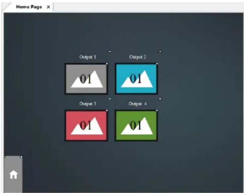
For the controller to print the port number of the assigned source on each screen and keep this information up-to-date, the controller needs to:
- constantly keep track of the assigned source
- constantly print the port number on each screen icon
Follow the steps below to create a professional monitor.

- In the Design tab, click Library 📄 and click Monitor 📷.
- Click to create a new monitor.
- Configure the following settings.
◆ From the Type drop-down menu, select Professional.
- Name the monitor.
♦ Define the query frequency.
- Configure the condition settings.
In this example, the controller VK2100 is set to query the input and output ports of the Matrix Switch, VM6404H, that connects to the controller every 0.1 second.
- Add the condition(s) that must be met for initiating actions. For details on conditions, see Condition Types, page 198.
- Select a Trigger Mode for the added conditions.
- And: Only initiate the added actions (commands) if the values of all specified inputs change.
- Or: Initiate the added actions (commands) if the value of any specified input changes.
- Independent: Use this option when you have multiple sets of actions. The added actions (commands) initiate if the corresponding set of inputs change in value.
- Always: Initiate the added actions (commands) at the specified frequency.
5. Configure the Action settings.
a) Click Edit to script the codes.
Note:
- This editor follows Lua’s programming rules. ATEN suggests using Notepad++ to script the codes before adding them to the Editor.
- For details on built-in commands, see Built-in Commands, page 215.
- When scripting codes for I/O inputs, use lower case “l” to represent the close status (e.g. input_io == ‘l’), and “h” to represent open status (e.g. input_io == ‘h’).
In this example, use Script Editor to:
♦ Convert data format.
- Create four variables representing the assigned input for each screen. In this example, InputNToOutput1, InputNToOutput2, InputNToOutput3, and InputNToOutput4 are created.
- Load the input number of the assigned source to the created variables.
Below is sample of the scripts used for this scenario:
function vk_parser(input)
    local vminput = vk_hex_toascii(input)
    -- local vminput = input
    if vminput == nil or vminput == "" then
    return
end

local map = {}
for vmout, vmin in string.gmatch(vminput, "o([0-9]*)i([0-9]*) video [^ ]* audio [^ ] * [^\n]** ) do
    map[vmout] = vmin
end

local vk_var_1_InputNToOutput1 = map["01"]
local vk_var_2_InputNToOutput2 = map["02"]
local vk_var_3_InputNToOutput3 = map["03"]
local vk_var_4_InputNToOutput4 = map["04"]

vk_doc commands_1_VMRead(vk_var_1_InputNToOutput1, vk_var_2_InputNToOutput2, vk_var_3_InputNToOutput3, vk_var_4_InputNToOutput4) end
b) Add actions.
In this example, add four Change Button Name commands:
Change Button Name SyncVM Home Page 01_2 to output InputNToOutput1 ASCII
For details, see Device Functions, page 171 and Advanced Functions, page 174.
Built-in Commands
| Command Description |
| jsonobj Converts JSON strings to tables. |
| vk_ascii_to_hex Converts strings from ASCII to Hex. |
| vk_doc commands_ID_name Defines the commands to be executed, e.g., vk_doc commands_1_output. A the user should define his/her own commands and their corresponding IDs. As long as the ID does not change, the command name can change.The same ID cannot be used for two different commands. The same applies to command names. |
| vk_hex_to_ascii Converts strings from Hex to ASCII. |
| Command Description | |
| vk_parser(input1, input2) | ◆ Use this command to indicate a start to a set of scripts.◆ The brackets should contain equal number of inputs that you added in the Professional Monitor setup.◆ If the Trigger Mode is set to independent, the script should contain only one input, but the number of parsers should match the number of inputs added to the Monitor, e.g. vk_parser_1(input), vk_parser_2(input). |
| vk_var_ID_name Create a variable. | |
Duplicating a Created Monitor
To duplicate a created monitor to another controller, right-click a monitor, mouse over Duplicate, and then select a target controller.
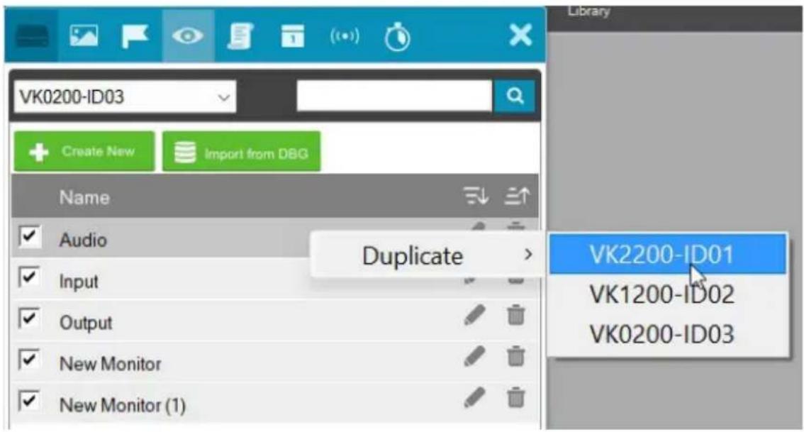

Macro
Macros allow you to create a button that will initiate a sequence of actions across the same or different hardware devices. This saves time by allowing multiple devices to initiate actions all at once from one button. For example, you can create a macro to start a video presentation by adding functions to: dim lights, power on source, power on display, lower screen and play source. You can also add time delays between actions in a macro. Each project can store up to 104 macros.
When you click opens:

from the Library's Macro tab, the window

To create a macro:
- Select Macro and click .
- Enter a Name and select a Viewer from the drop-down menu, then click OK.
- Go to the Actions section at the bottom of the page to select hardware under Device and add the Function to the Commands list:
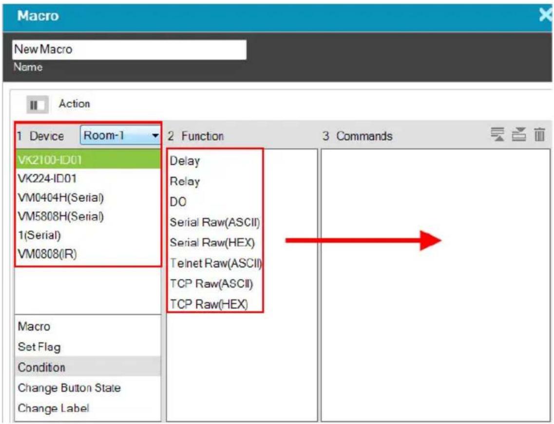
Note: For more information about adding Functions, see Button / Slider Bar / Dial Kit Actions, page 166.
- After adding all the functions to the Commands list, the macro is complete.
- In Create Viewer & Design, create a button and add a macro to the Button Action properties (see page 166) by selecting Macro under Devices (see Device Functions, page 171 for details).

Scheduled Events
You can have one or a series of tasks execute recurringly on specified time of the day. Each project can store up to 60 scheduled events. Note that this feature is not applicable to Control Pads.
Creating a Scheduled Event
-
In the Design tab, click Library and click Schedule
-
Select a controller to which you wish to create an event.

- Click . A new event window appears.
- Name the event.
- Click to specify a recurring schedule for the event.
- Configure event actions.
a) In the Device column, select a device.
b) In the Function column, double-click the desired functions. The corresponding commands appear in the Commands column. For details on what each function does, see Device Functions, page 171.
c) In the Commands column, double-click each command to configure the settings.
-
Optionally add system functions. For detailed information, see Applications of Advanced Functions, page 176.
-
These commands will initiate in the listed order. To change the order of the commands, click .
Duplicating a Scheduled Event
To duplicate a created event to another controller, right-click an event from the event list, mouse over Duplicate, and then select a target controller.


Variables
Understanding Variables
A Variable is a value holder that stores a single device setting (e.g. speaker volume) and can be assigned to multiple control objects (e.g. a slider button, a maximum volume button, and a minimum volume button). This way, when a device setting is adjusted via a Viewer object, the new setting will be loaded into this Variable and then reflected to all Viewer objects that use this Variable. Each project can store up to 128 Variables.
Below is a Variable list that has two variables created, temperature and speaker volume, for devices controlled by VK1200-ID02.

This feature is useful for automatic synchronization of device settings, especially when you have two or more objects in a Viewer controlling a single device setting. Take the example of controlling a speaker volume on a Viewer. On your Viewer, you may have a slider bar which you use to adjust the volume, a button that sets the speaker to its maximum volume, and another button for minimum volume. When you tap the maximum volume button, you would like the following status changes reflected on the Viewer:
◆ The maximum volume button shows a toggle-on status
- The minimum volume button synchronized with this setting and shows a toggle-off status
- The slider bar synchronizes with this setting and moves to its highest volume
Creating a Variable for Devices that Return Feedback Messages
Follow the steps below to configure a Variable if the Variable (device setting) is for a device that returns feedback messages to the controller.
- Create a Variable for the device setting (e.g. speaker volume).
a) In the Design tab, click Library.
b) In the pop-up window, click the Variable (●) icon.
c) Using the indicated drop-down list, select the controller which controls the target device. The variables created for the devices managed by the selected controller are listed.
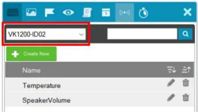
d) Click . A Variable setup page appears.
e) In the setup page, configure the following settings.
◆ Name: Type a name for the Variable.
- String format: Select the string format for the target device.
Setting range: Type two numbers to define the range for the variable. Valid numbers include negative numbers and numbers that contain one decimal place.
Note: If one of the numbers contains a decimal place (e.g. -5.0), make sure to specify the other number in the same format (e.g. 10.0).
- Unicode: (Only available for string variables) Select this setting for multilingual text to be encoded and represented correctly in the variable.
◆ Default value: Type a default for the setting.
◆ Description: Optionally add additional information for the variable.
Your settings may look like this:

- Configure control objects for the Viewer. For details, see Configuring the Control Interface (Viewer), page 127.
a) In the Design tab, add control objects to your Viewer.
Note: The Variable function is only applicable to toggle buttons, basic-mode slider bars, and radio groups of normal buttons. Configure the Mode setting before you proceed.

b) For a slider bar object, click it in the Viewer page and configure the Value settings in Properties.
c) In Properties, click Set Sync Condition and select the variable you created using the drop-down list.
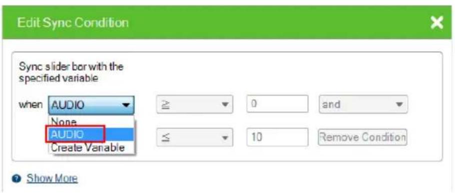
- Create a Monitor to set up the conditions for which the device sends its latest setting to the variable. For detailed steps, see Creating a Bypass Monitor, page 209.
Creating a Variable for Devices that Do Not Return Feedback Messages
Follow the steps below to configure a Variable if the Variable (device setting) is for a device that does not return feedback messages to the controller.
- Create a Variable for the device setting (e.g. speaker volume).

a) In the Design tab, click Library.
b) Click the Variable (●) icon.
c) Using the indicated drop-down list, select the controller which controls the target device. The variables created for the devices managed by the selected controller are listed.
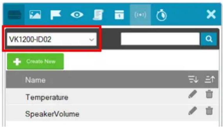
d) Click . A Variable setup page appears.
e) In the Setup page, configure the following settings.
- Name: Type a name for the Variable.
- String format: Select the string format for the target device.
Setting range: Type two numbers to define the range for the variable. Valid numbers include negative numbers and numbers that contain one decimal place.
Note: If one of the numbers contains a decimal place (e.g. -5.0), make sure to specify the other number in the same format (e.g. 10.0).
- Unicode: (Only available for string variables) Select this setting for multilingual text to be encoded and represented correctly in the variable.
Note: This feature is only effective if the target controller uses firmware v3.6 or later.
- Default value: Type a default for the setting.
◆ Description: Optionally add additional information for the variable. -
Select a command execution type.
-
Execute commands with no conditions: Execute the command (action) when the value of the specified Variable changes.
-
Execute commands with the specified conditions: Execute the corresponding command (action) when the value of the Variable matches.
-
Configure control objects for the Viewer.
a) Add a control object to the Viewer. For details, see Configuring the Control Interface (Viewer), page 127.
Note: Make sure to configure the mode setting before proceeding to the next step.
b) For a slider bar, click it and configure value settings in Properties.
c) Click Set Variable, and then double-click the Variable you created in step 1.
d) In Properties, click Set Sync Condition and select the Variable you created using the drop-down list.

- Repeat steps (a) to (d) with each of the objects. If you select Execute commands with the specified conditions, follow the steps below to add commands.
a) Refer to step 4 to first configure the control objects.
b) Click Library, click the Variable (●) icon, and then click the Variable you created in step 1.
c) Click the drop-down list below the Execute commands with the specified conditions option and select a condition.
d) Add an action (command) when this condition is met. Select a device, double-click a desired function, and then double-click the command to configure the setting.
In the case of speaker volume, when the volume changes to 0 (i.e. the condition is Variable = 0), the action will be “to change the speaker volume to 0”, as illustrated below.
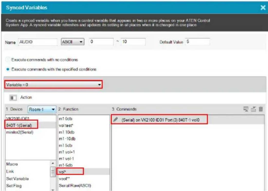
e) Repeat steps 2(c) and 2(d) to add one or more actions to each condition.
- If you select Execute commands with no conditions, follow the steps below to add commands.
a) In the Device list, click to select the device. In this example, the mixer, 840T-1(Serial), is selected.
b) Double-click the action (command) and change the value type to Variable Value.

Creating a Button for Bypassing Feedback to a Variable
Instead of creating a monitor event which automatically monitors the specified parameter at a defined interval, you can save the controller bandwidth by creating a button which performs the monitoring and saves the feedback to a variable only when pressed.
- Create a variable for storing the received feedback. Select STRING for the variable. Configure other settings as required.

a) In the Design tab, click Library.
b) Click the Variable (●) icon.
c) Using the indicated drop-down list, select the controller which controls the target device. The variables created for the devices managed by the selected controller are listed.
d) Click . A Variable setup page appears.
e) In the Setup page, configure the following settings.
◆ Name: Type a name for the Variable.
◆ String format: Select STRING.
- Unicode: (Only available for string variables) Select this setting for multilingual text to be encoded and represented correctly in the variable.
◆ Default value: Type a default for the setting.
◆ Description: Optionally add additional information for the variable.
- Select a command execution type.
- Execute commands with no conditions: Execute the command (action) when the value of the specified Variable changes.
-
Execute commands with the specified conditions: Execute the corresponding command (action) when the Variable matches
-
In a Viewer page, create a button object.
-
Configure its button actions.
a) Add a command for receiving feedback.
b) Select Condition and then drag-and-drop a Feedback If command under your feedback command.

c) Set the feedback to bypass.
- Add a variable command. Select a variable to store the feedback and then select Bypass.

Timers
A timer event is used to initiate a device action as soon as the defined countdown time is up. The advantage of using a timer event, as opposed to a combination of delay command and device command, is that it saves time by executing the defined action while other actions (commands) within the series execute.
On top of initiating a specified action, you can also create additional controls on the Viewer to manually restart or stop the action. For example, for a start meeting button, you would like to initiate the following series of actions when triggered:
| Sequence of Action | Target Device | Device Action Requirements | |
| 1 | projector the projector to switch | Turn on the projector It takes to its HDMI source | 8 seconds for the projector to turn on and get ready. |
| 2 Set | This action can only be initiated when the projector is turned on. | ||
| 2 | A T E Switch | Display input Mto display 1 via ATEN Matrix Switch (VM5808H) | fThis action is independent of the previous one, and can be initiated at the same time. |
| 3 projector screen Bring | down the projector screen | - | |
| 4 air conditioner Turn on | air conditioner | - | |
| 5 lighting system Turn on | the lights | - | |
Among these actions, action #2 (switching source on a projector) can be designed as a timer event because:
- it needs a countdown (of 8 seconds) before the action can be initiated
◆ the remaining actions can be initiated without action #2 being completed
The configuration for the start meeting button is as follows, with the projector source switching configured as a timer event:

Configuring a Timer Event
- Create a timer event in the Library.
a) In Configurator, go to 3. Design > Library 📄, and then click Timer in the pop-up window. This screen appears.
b) Select a controller to which you wish to create the timer event to.
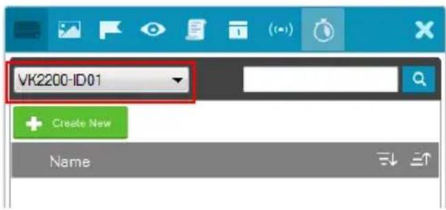
c) Click . The Timer window appears.
d) Add a device action (command). For more details about commands (device actions), see Configuring Button/Slider Bar Actions, page 168. For example, for a projector to switch its input source to HDMI, click the device in the Device column and then double-click the input source
command from the Function column. Double-click the added command to select HDMI for the Input Source.

To see only the added actions (commands) in this view, click

e) Rename the timer event and configure the countdown duration.

- Apply the timer to a control element (e.g. a button or a slider bar).
a) Click the target control element.
Example: a meeting start button
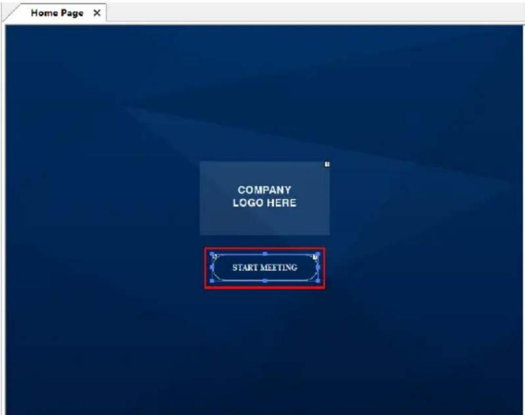
b) In Action settings, click the target device (for the timer event), click Timer, and then double-click a function to add a timer event.
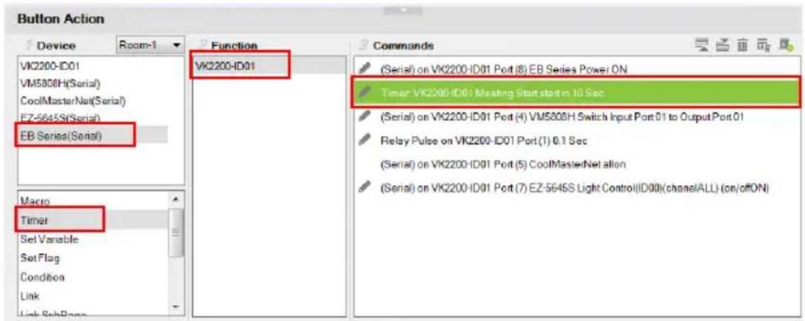
c) To configure the timer, double-click the added timer in the Commands column and select from the drop-down menus.

The following settings are available:
- controller:
- timer: to change the current timer to another that is already created in the Library.
- timer type: you can change the action from starting a specified action to stop or restart.
◆ countdown duration
The timer action starts counting down as soon as the associated control is triggered, and the action initiates when the countdown time is up.
- (Optional) Create another control (e.g. a button) for stopping or restarting the timer.
a) Add the control element to the Viewer page.
b) Click the control element, and add the timer event you created in step 1, and double-click the command to select Restart or Stop from the dropdown list.

Duplicating a Created Timer
To duplicate a created timer to another controller, right-click a timer, mouse over Duplicate, and then select a target controller.

Centralized Monitoring and Control via Unizon™
Overview
Unizon™
Unizon ™ is a server-based software for centralized monitoring and control of standalone ATEN Video Matrix and ATEN-controller-managed AV devices, including ATEN and third-party devices. One ATEN control system allows management from up to two Unizon ™ servers. Note that a license is required for using Unizon ™ . For more information, see ATEN Unizon ™ User Manual.
Monitor ATEN-controller-managed Devices via Unizon™
When an ATEN-controller-managed AV device is added to Unizon ™ , the following information is available in the Unizon ™ platform:
♦ connection status with Unizon™
- current IP address
◆ firmware version
◆ license usage (only applicable to ATEN controllers)
You can also create parameters to be monitored via Unizon™. For example, you may want to monitor the total hours used on a projector lamp so that you can arrange for replacement in advance when the accumulated lamp hour reaches a specified number. For setup details, see Creating a Monitor Item, page 239.
Control ATEN-controller-managed Devices via Unizon™
You can remotely operate ATEN-controller-managed devices via Unizon ™ , such as switching video sources on displays, changing the resolution setting, etc., by creating control items in the controller project file. For setup details, see Creating a Control Item, page 242.
Enabling Monitoring and Control via Unizon™
Follow the steps below to enable monitoring and control of controller-managed devices via Unizon TM .
- In Configurator, select devices to allow management via Unizon TM .
a) Open the target project and go to the Device tab.
b) In the Unizon column, select devices for remote management via Unizon™. For example:

- (Optional) Create parameters for monitoring and/or control. For detailed steps, see:
♦ Creating a Monitor Item, page 239
♦ Creating a Control Item, page 242
-
Upload the project to the controller.
-
On Unizon™'s web interface, add the controller. For details, see ATEN Unizon™ User Manual.
Creating a Monitor Item
- Open the project file, go to Design >Unizon, and click on the device category of the target device to open the configuration page.
Example: To add a monitor item to a third-party projector, click Projector.

- In the configuration page, click
and then select Item

Add Monitor Item in a pop-up dialog box. A new monitor item is added.

- Double-click the header Monitor Item to rename the parameter.
Example: Rename it to Lamp Hour.

- Create a variable to store the value of the parameter and optionally configure alert settings.
Example: Create a variable to store the accumulated lamp hour and set up an alert at a specific number.
a) Under the monitor item you just created, click Sync Variable. The Properties panel appears on the right.
b) In the Properties panel, click Set Sync Condition. The Edit Sync Condition dialog box appears.
c) In the General tab, click the first drop-down menu and select Create Variable to create a variable. For details about creating variables, see Variables, page 222.
d) In the General tab, select the variable you just created and configure related settings. For example:

e) Optionally set up alerts for this monitor item. For example:
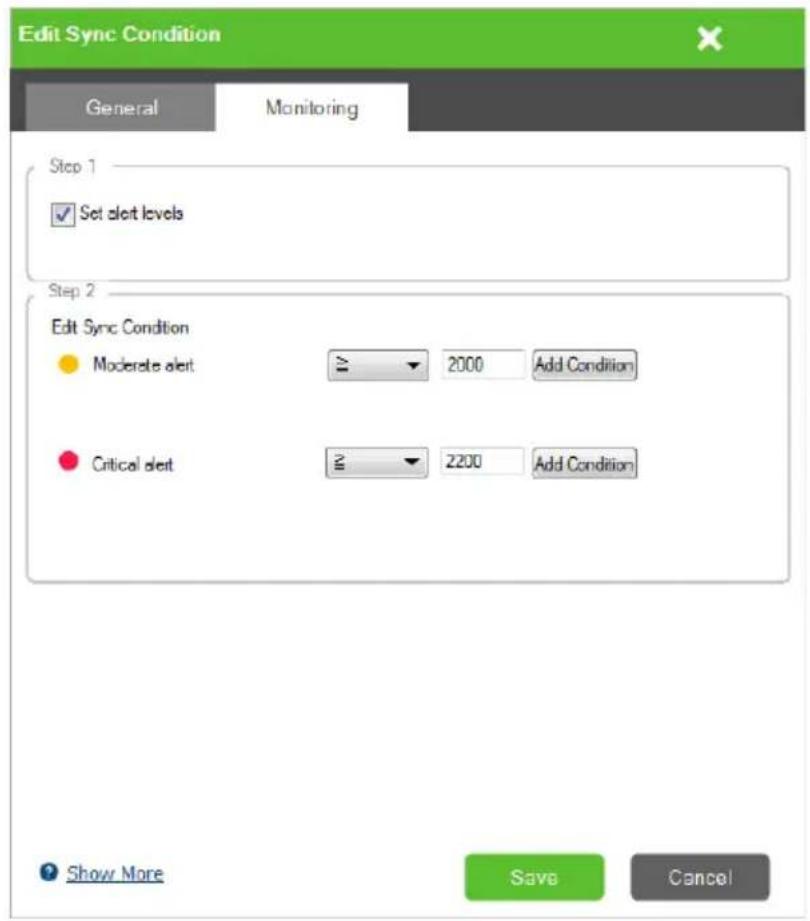
Creating a Control Item
- Open the project file, go to Design >Unizon, and click on the device category of the target device to open the configuration page.
Example: To add a control item to a Video Matrix, click Video Matrix Switch.

- In the configuration page, click
and then select Item
Add Control Item in a pop-up dialog box. A new control item is added.
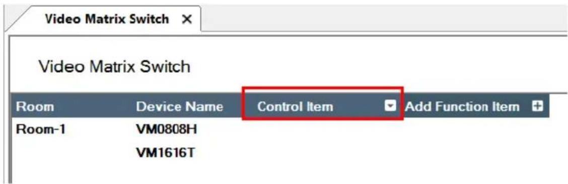
- Double-click the header Control Item to rename the parameter.
Example: Rename it to Output 1.

- Add and configure control options to this item.
Example: Create input 1 to 4 as options for switch the source on output 1.
a) Click
b) In the pop-up dialog box, type the name of the control option and click Create. Proceed to create all the control options as required.
Example: Type Input 1 and click Create. Add Input 2, 3, and 4.

c) Click Input 1 and add the action in the Action panel. Proceed to configure each control action.
Note:
- The same entries are created for all devices in the list. Skip this step if the control action does not apply.
- For full details about configuring control actions, see Configuring Button/Slider Bar Actions, page 168.


Removing a Monitor / Control Item
To remove a monitor or control item, right-click the header and select Delete.
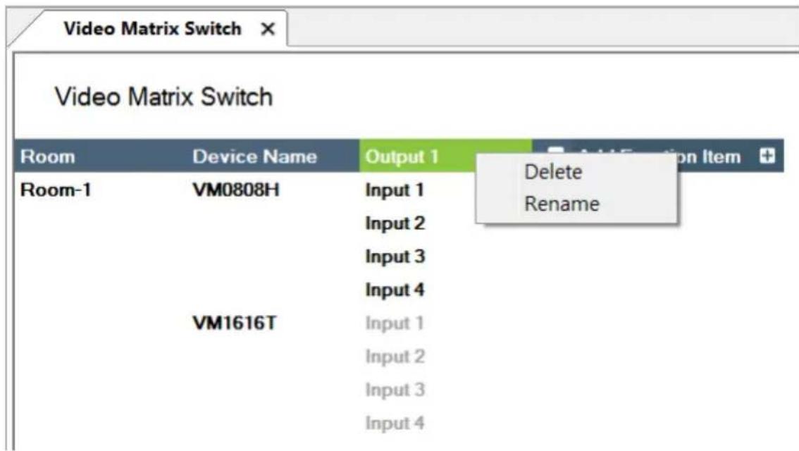
The Upload Tab
The Upload page allows you to upload Viewers and/or back up projects to controllers.

To back up a project and its Viewers to a controller:
-
Browse for the ATEN controller where you wish to save the configured Viewers.
-
Auto Search: Browsers for controllers on the same LAN with the Configurator.
-
Search by IP address: Use this function to browse for controllers that are on different LANs to the Configurator.
-
Verify the selected controller and viewer and configure the selection if required.

- Controller highlighted black: This is the controller that is found in the network and its ID matches the one you specified in this project file. The viewers created for the controller are listed below this item.
- Controller highlighted gray: This is the controller that also exists in the network, but does not match the controller ID specified in this project file.
- Optionally click on the following to configure password authentication settings.
Note: Due to security concerns, the access key of any ATEN controller will need to be modified at least once before the controller can be accessed for any of its functions. If you have not modified the access key, the upload will not be performed. To resolve this issue, log in to the controller's web interface and follow the on-screen prompt to modify the access key.
- Edit Access Key: Click to edit the access key you entered for uploading Viewers to the controller and download Viewers from a mobile device.
Note: A valid access key should only contain upper-case alphabets,
lower-case alphabets, and/or numerals. : An access key is required to upload Viewers to the controller and download Viewers from a mobile device.
◆ : An access key is not required to upload Viewers to the controller and download Viewers from a mobile device.
- : The access key has been changed on the controller's web interface (Dashboard). To change the lock status, click on the icon and type the new access key to proceed.
4. Click Upload to Controller.
Note: By default, the project file is uploaded along with your selected Viewers. To only upload the selected Viewers, click Also upload project file to disable the function.
Viewing Controller Information
Click to view the controller's information.
♦ IP Address: Displays the IP address.
♦ MAC Address: Displays the MAC address.
◆ License: Displays the number of licenses available and in use.
- Select License: Allows you to load a new license file.
- Reset License: Resets all license(s) in use by mobile devices. This will disconnect all mobile device connections to the controller.
- Firmware Version: Displays the firmware version.
◆ Capacity: Displays the amount of space available for uploading Viewers.
- Viewers: Lists the Viewers currently stored on the controller.
- Remove Viewer: Click the trash can icon to remove the Viewer stored on the controller.
◆ Project: Lists the project file currently stored in the controller.
This Page Intentionally Left Blank
Chapter 5
ATEN Database Generator
Overview
The ATEN Database Generator is a repository that allows you to establish and store commands for operating devices managed by ATEN Control System, and reuse them when configuring Viewers.
Accessing the Database Generator
In ATEN Configurator, goto Tools > Database Generator. The following window appears with the Add Device to My Library dialog box opened if you are accessing the Database Generator for the first time.

| Menu Description | |
| Add New Device Configure a custom hardware device to add to My Library. | |
| Add Device from ATEN Device Library | Add devices from the ATEN Device Library to My Library. |
| Add Device from Driver File | Add devices from a database file (*.vkd) to My Library. |
| Check Box | Click Do not show this dialog again to prevent the dialog from appearing when the Database Generator is opened. Use the Preferences menu option to bring the dialog window back. |
| Close Click the Close | button to exit the dialog window. |
| Add New Device Configure a custom hardware device to add to My Library. | |
My Library
My Library allows you to create custom hardware devices which can be selected to configure ports on the controller. My Library lists all the hardware devices that you have created, added, and edited using the Database Generator. You can create new hardware devices or add existing devices from the ATEN Device Library (page 274). These devices can then be selected from My Device Library for use.


Function Tabs
More functions can be accessed from the function tabs toward the top of the My Library window. Refer to the table below for information about each function.

Tab Description
File The File menu provides options to:
- Add New Device: Configure a custom hardware device to add to Device Library.
- Add Device from ATEN Device Library: Add devices from the ATEN Device Library to My Library.
- Add Device from Driver File: Add devices from a database file (*.vkd) to My Library.
- Export My Library: Saves My Library as a database file (*.vkd) that can be imported later.
- Export Selected Device: Saves the selected device(s) as a database file (*.vkd) that can be imported later.
- Controller Connection: Searches for a controller to test the connection or run the learning mode for the IR port.
- Quit: Exits the program.
| Tab Description | |
| Edit The Edit menu provides options to:Delete: Deletes the selected devices from the database.Duplicate: Makes a copy of the selected device(s) and adds them to the library with the extension “-Copy”Preferences: Provides options to:Set the LanguageShow Add Device dialog on startupShow IR Learning tipsSet the IR Learning Timeout - how long to attempt a connection to an IR device before IR learning stops. | |
| Library Provides a list of the Libraries that you can open to select devices from and edit or add to My Library. The libraries that are listed here appear when you select a database using Add Device from Driver File. | |
| Help Provides support and software version information. |
Controls on the My Library Window
You can add new devices by creating a new device, duplicating an existing device, selecting a device from the ATEN Library or importing a driver file. Use the check boxes to select individual devices or All to select the entire list.


Click to add a new custom device to the database.

Select a device and click this icon to create a duplicate.

Click to add and edit a device from the ATEN Device Library.

Click to add a device from the driver file.
EDIT
Select a device and click Edit to change the settings.
Search
Key in word strings then click Search to find a device.
- Click All, Serial, IR, DO, Relay or Ethernet to filter the list by type.
- Click Brand, Category, Model, Type or Version to sort the devices.
- Click Export Selected Device to save the selected devices.
- Click Delete Selected Devices to remove the selected devices.
Editing / Adding a New Device
To edit or add a device to My Library, do the following:
- From the menu select File → Add New Device, or select a device from My Library and click Edit.
- Under General, use the drop-down menus or type in the Brand Name, Category, Model and Version.
Note: The Category determines what buttons are auto generated when a Viewer page is created for the device. - Use the History button to open the Version History editor and make notes about the updates being made to the device configuration. You can create and use different versions of the same device and track the changes. The version history can be viewed and different versions selected from the ATEN Configurator, under device Properties.
-
Check the hardware type and configure the device. ATEN database generator supports serial, IR, digital output, relay, and Ethernet devices. For more information about configuring each of these device type devices, refer to the following sections.
-
Serial: See Serial Device, page 257.
- IR: See IR Device, page 261.
◆ Digital output: See Digital Output Device, page 263.
♦ Relay: See Relay Device, page 264.
◆ Ethernet: See Ethernet Device, page 265.
Serial Device
![ATEN Database Generator File Edit Library Help ATEN Presentation Switch VP1420 Save Save As Cancel General Brand ATEN Category Presentation Switch Model VP1420 Version V1.1.103 History Type Serial IR Digital Output Relay Ethernet Settings Baud Rate 19200 Data Bit 8 Stop Bit 1 Parity None Flow Control None Mode RS232 Listen Advanced Function List Serial R DO Fisky Ethernet String Format HEX ASCII + Command Message Display mode * displaymode [matrix, mirror]x0D/x0A Edit Send Echo * echo [on, off]x0D/x0A Edit Send Get Device Status read x0D/x0A Edit Send Get FW Version read version x0D/x0A Edit Send Get Output Audio... mute o[all=*,sys,01-03]x0D/x0A Edit Send Get Output Audio... read o[all=*,01-03] connection Edit Send Get Output Scale... scaling o[all=*,01-02]x0D/x0A Edit Send Get Output Video... read o[all=*,01-02] connection Edit Send Get Standby Stat... standby x0D/x0A Edit Send Mute Output ** mute o[all=*,sys,01-03] [on,off]x0D/x0A Edit Send Power on power onx0D/x0A Edit Send Standby * standby [on, off]x0D/x0A Edit Send Switch Input * to ... sw i[01-04] o[all=*,01-02]x0D/x0A Edit Send Switch mode * swmode plugin [auto, off]x0D/x0A Edit Send](/content/2026/05/1091984/images/03a14e595cf1a363ae81c89bf5cbc1e296536e8833acf7a58c9a654092e2fa4a.jpg)

Click to add an Action.

Click to create a duplicate of the Action.

Click to delete the selected action.

Click to enter a string within () which allows the text to be edited in the VK6000 in the Button Action - Commands list (see page 168).

Click to add a drop menu into a Command string, then enter the ber sequence in the brackets []. The Function name must include sterisk (*) for each drop menu in the Command string. The drop- n menu will appear where the (*) is entered in the Function name.

Click to add an Enter into the Command string.
Right-click one or more serial commands to copy and paste them as Ethernet commands of all protocols (except HTTP/HTTPS):
![Function List Serial IR DO Relay Ethernet String Format HEX Copy Paste Duplicate Delete Message Echo* Edit Send Get Device Sta Edit Send Get FW Version read version\x0D\x0A Edit Send Get Output Audio... mute o[all=*,sys,01-03]'x0D\x0A Edit Send](/content/2026/05/1091984/images/ac6fe540eaa2660e1622933e79a5ef1dc1d5bc57a021da348dc3ebac5c3b7fb3.jpg)
- Settings – Use the drop-down menus to set the: Baud Rate, Data Bit, Stop Bit, Parity, Flow Control and Mode settings.
- Listen – Use this function to create a list of device parameters that you want the controller to monitor by receiving notifications on setting or status changes of the specified parameters.
Note: To set up queries for the status of a device parameter, go to the Function List and click to add the querying action as a command.
- Advanced
- Delay Interval – Sets a time delay for each command before they are sent to the device.
- Feedback Timeout – Sets the maximum interval that the controller allows in between parts of a feedback message. If the controller has not received any feedback for longer than the specified Feedback Timeout, the controller identifies the last bit of the received information as the end of a feedback message.
- Receive Duration – Sets the allowed duration of time for the serial device to receive a complete message from the controller.
- Checksum Type – To have the checksum automatically calculated and filled in by the controller, select Modbus for this setting.
- Keep Connection Alive – Specify an interval that the controller waits before sending the specified command to test if the connection to the serial device is up or down.
- Function List – Use this section to configure the device functions by adding actions to the list.
- String Format – Use the buttons to select HEX or ASCII. To use HEX strings with ASCII one, select ASCII and type \x before typing the HEX strings.
Note: HEX strings are also supported under the ASCII format.
- Function – Lists the actions created for a device. A Function name must include an asterisk (*) if you are adding a drop menu to the Command string. Double-click to edit the function name.
- Command – Shows the command string created for the action. Double-click to edit the string.
-
Message – The Message column is used to create and store feedback and/or queries for the corresponding command.
-
For more information about adding feedback, see Testing Commands, page 270.
- For more information about creating queries, see Configuring Queries, page 272.
- Click Send to connect to a controller and test the typed command.

- Click to select a controller from the list. Use the Refresh button to refresh the list. To browse for controllers in the LAN, click the Intelligent Search button or type the IP address of the controller.
- Click OK to proceed to test the command. For details, see Testing Commands, page 270.
Text Command Tools
The following formats allow you to enter command strings with text that provide special features. These formats work in Serial and Ethernet commands.
- () entering text in () allows the command to be edited in the VK6000.
Example: (A1 A9) (A8 B6) – this command string will provide two editable text boxes from the VK6000 in the Button Action - Commands list which allow you to change the command string:

◆ = using the equals sign before a text command allows you to type in words which will show up in a drop-down menu to describe the command, rather than show the text command itself.
Example: [Power On=0A, Power Off=0B, Standby Mode=0C] – this command string will provide a drop-down menu with three choices using the text before the equal signs to describe each command – from the VK6000 in the Button Action - Commands list:
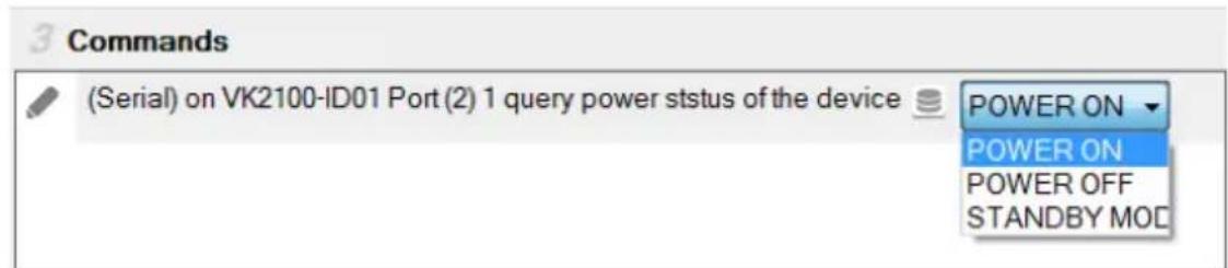
◆ “” quotation marks allow three symbols (, = @) to be added to a command that uses the equal sign as described in the example above. Three symbols not allowed within the quotation marks include (“” () []). Quotation marks can be used to the left of = in a HEX command; on either side of = in an ASCII command; and anywhere in an Ethernet command.
HEX Example: ["Power=On" = 0A, "POWER=Off" = 0B]
ASCII Example: ["Power=On" = pwn, "POWER=Off" = pwf]
In the HEX example, “Power=On” allows the equal sign to be inserted before =0A. If the quotes are removed, the command Power=On=0A would fail as an Invalid String.
IR Device


Click to add an Action.

Click to create a duplicate of the Action

Click to delete the selected action.
- Settings – Use the drop-down menu to set the Repeat setting (number of times a signal is sent): 1 Time, 2 Times or 3 Times (Default).
◆ Advanced
- Delay Interval – Sets a time delay for each command before they are sent to the IR device.
- Receive Duration – Sets the allowed duration of time for the IR device to receive a complete message from the controller.
- Function List – Use this section to configure the IR functions by adding actions to the list.
- Click to add an action. In the pop-up dialog box:
- Auto Learn: Select this option to add the action through learning,
- Manual Input: Select this option to add the action using Pronto hex codes. Double-click the command to enter the Pronto code for the device.
Note: To obtain Pronto codes for a control system managed, third-party device, search Internet forums or the manufacturer's product web pages.
- Quick Mode – Click to run Learning Mode for all IR actions in the Function List. When the Quick Mode window opens, click Start, a pop-up window appears to select a controller. Check a box to select a controller and click Select. Click Start a second time to run Quick Mode using the Learn instructions below.
- Function – Lists the actions created for a device. Double-click to edit the Function the name.
- Status – Reports the status (Tested, Failed, Learned) of the Learn and Test buttons.
- Learn – Use to transfer commands from an IR remote to the Control Box. Click Learn. The Select Controller window appears.
- Click to select a controller from the list. Use the Refresh button to refresh the list. To browse for controllers in the LAN, click the Intelligent Search button or type the IP address of the controller.

- Click Learn a second time to start learning mode. When the IR Learn LED flashes green, point the IR remote at the Control Box's front panel IR Receiver and push a button on the remote. Press the button on the remote just as you would when using it with the hardware device. If the device responds to a long hold or quick tap of the remote's button then you must press the button in the same manor (long hold or quick tap) when it using for Learning mode. The Control Box will beep and the Learn LED will light solid (then turn off) when IR learning is successful. The LED also turns off if Learning mode times out.
- Test – Use to test if commands are sent successfully to the Control Box and hardware device.
- Click Test, a pop-up window appears to select a controller and the IR port. Check a box to choose a controller and use the drop-down menu to select the IR port and then click Select.
- Click Test a second time to test if the IR data transmits successfully to the Control Box. Check the hardware device to confirm that it responded appropriately.
- The Status column reports the Learn and Test results.
Digital Output Device


Click to add an Action.

Click to create a duplicate of the Action

Click to delete the selected Action.
- Advanced – Click to use the Delay Interval drop-down menu to set a timed delay for each command before it is sent to the device.
- Function List – Use this section to configure the Digital Output device functions by adding actions to the list.
◆ Function – Lists the actions created for a device. Double-click to edit the Function name.
- Command – Shows the command selected for the action. Click the drop-down menu to select an action (Open, Close, Toggle, Pulse).
Relay Device
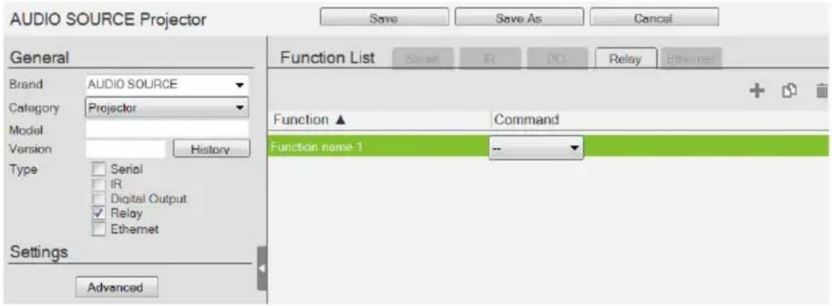

Click to add an Action.

Click to create a duplicate of the Action

Click to delete the selected Action.
- Advanced – Click to use the Delay Interval drop-down menu to set a timed delay for each command before it is sent to the device.
-
Function List – Use this section to configure the Relay device functions by adding actions to the list.
-
Function – Lists the actions created for a device. Double-click to edit the Function name.
- Command – Shows the command selected for the action. Click the drop-down menu to select an action (Open, Close, Toggle, Pulse).
Ethernet Device


Click to add an Action.

Click to create a duplicate of the Action.

Click to delete the selected action.

Click to enter a string within () which allows the text to be edited in the VK6000 in the Button Action - Commands list (see page 168).

Click to add a drop menu into a Command string, then enter the ber sequence in the brackets []. The Function name must include sterisk (*) for each drop menu in the Command string.

Click to add an Enter into the Command string.
Right-click one or more Ethernet commands (except HTTP/HTTPS) to copy and paste them as serial commands:
![Function List Serial IR DO Relay Ethernet + - Function ▲ Copy Command Feedback Trun on OutputPart* Paste sw o[01-04] onxDv0A Duplicate Delete](/content/2026/05/1091984/images/f94d55dd448c7afd1f67add6134300619b8da05dbf94c646d1b7c77a9b56207f.jpg)
For special command string tools, see Text Command Tools, page 260.
- Settings
- Protocol – Click the drop-down list to select a protocol for the device
- Port – Type the port number for the device.
- Advanced – Click to configure the following settings. The supported settings may vary depending on the device protocol and authentication type.
| Delay Interval Sets a | time delay for each command before they are sent to the device. |
| Delay Time after Login | Sets a time interval that the controller waits to request for login credentials of a device after establishing connection with the device. |
| Receive Duration Sets | the allowed duration of time for the Ethernet device to receive a complete message from the controller. |
| Send command after successful connection | Enter a First and Second Command to send to the device after a successful connection has been established. |
| Auth Type Sets the authentication type for the device. | |
| Timeout Specifies the maximum time that the device allows for receiving each feedback message from the device before timing out. | |
| URI path | Type the part of the WebSocket URI that follows its communication port. For example, if the URI is wss://:31416/Dicentis/API, type /Dicentis/API in this field. |
| Sub-protocol | Type the subprotocol for the Ethernet device. This information shall be available in the device's reference or user manual. |
| ExHeader Type the required data for handshake header. | |
| Extension | Type the required data for the Sec-WebSocket-Extensions header field. |
| Login Command Sets the command for logging in to the device. | |
Parameter Sets the parameters (keys) of the device that are required for the controller to connect to the device. For example, the device username and password are required when connecting to the device, and the valid values are admin and 123456 respectively.
| Keep Connection Alive | Specify an interval during which the controller sends the specified command to make sure the it is connected to the Ethernet device. |
| Automatically reconnect if no return message is received | Check this box if you want to continue reconnection attempts when no return message is received from the device. |
| WSS Select to encrypt the WebSocket connection. | |
| Use Default Click this button to restore to default settings. | |
- Function List – Use this section to configure the device functions by adding actions to the list.
- String Format – Use the buttons to select HEX or ASCII. (TCP only)
- Function – Lists the actions created for a device. A Function name must include an asterisk (*) for each drop menu you add to the Command string. Double-click to edit the function name. The dropdown menu will appear where the (*) is entered in the Function name
- Command – Shows the command string created for the action.
- To edit a command for a Telnet, PJLINK, ONVIF, or TCP compliant device, double-click the Command field (green area in the interface).
- To edit a command for an HTTP or HTTPS compliant device, click the Edit button. The Edit HTTP Command window appears.

- Feedback – Stores return messages generated by testing the command strings. Double-click to manually add or remove stored messages. This function is not applicable for ONVIF devices.
- Send – Click this button to test the command for the function. The return messages can be saved to Feedback.
This screen appears when Send is clicked. Select a controller for the device to connect and configure the fields such as device IP address.

| Intelligent Search Click | to locate controller without specifying an IP address. This option only searches for controllers on the same local area network. For controllers across a network device, such as a router or switch, you must specify the IP address. |
| Search by IP address | Enter the IP address and click Search to locate a controller. |
| Controller ID Use the c | check box to select the Controller, fill in the IP Address, Username and/or Password and then click OK. Next use the instructions below this table. |
| Refresh Click this button | to refresh the Controller ID list. |
| IP Address Type the IP | address of the device. |
| Username Type the dev | vice's username. |
| Password Type the dev | vice's password to grant access right to the controller. |
| Receive message for S | specifies the maximum allowed time that the device receives messages from the selected controller. |
Note: The username and password are not required for UDP and TCP devices, and the username is not required for PJLINK devices.
Testing Commands
After selecting a controller for the device and configure the required settings (if any) in the select controller window, click OK to proceed to test the typed command. The Test Command window appears.

Select which device to send command to by choosing Send to all or Send to specific and then click Send Test Command. This window appears.

The test results will appear in the yellow area of the window and the feedback messages listed in the Feedback column.
- Add – Click to save a feedback message in the Saved Feedback message window.
- Pause / Continue – Click to pause sending/receiving the command/return message.
- Save & Exit – Save the feedback messages to the list and close the window.
Configuring Queries
You can set up queries to actively monitor parameters of a serial or Ethernet device and store the obtained value into a variable for reuse in a control system project.
Take the example of querying the cumulative number of hours that a projector lamp has been used to be able to estimate the remaining lifespan and plan for replacement in advance.
- In Database Generator, click Edit to enter the settings page for the projector.
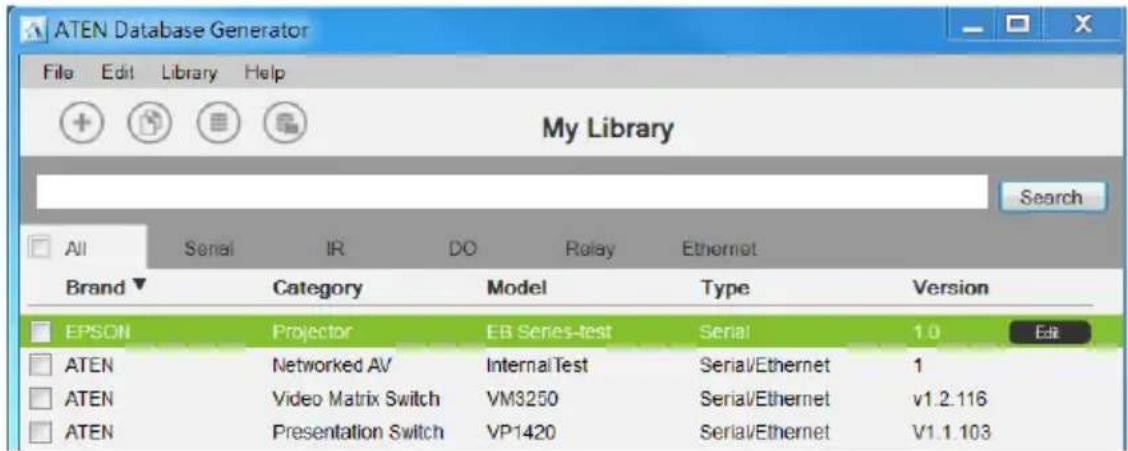
- Add a command by clicking and double-click the command column to type the command of requesting for the cumulative lamp usage (hour). Consult the user manual for the device to find out the operation command.

- Set up a variable to store the queried value.
a) In the Message column, click Edit. The Edit Messages window appears.
b) Click the Script tab and click +Add Script and name the script.
c) Write up a script to create a variable that stores the requested value, in this case, the cumulative lamp hour.
![Edit Messages Feedback Script Read Lamp Hour 1 Edit Script Script Information Query 0.1 Sec Trigger Mode and function vk_parser(input) if input == nil or input == "" then return end for index, hour in string gmatch (s, "LAMP(%?+)") do local index = tonumber(index) projectorInfoTable[index] = {} _G[Projector_TAG_DEFINE_LAMP] = hour end 2 Configure Variable Variable List Name Way Range Default vk_var_ S_ NULL + Add Script Next Save](/content/2026/05/1091984/images/8b17fc23c639252133a54037f2ad9bee119e4f81712e41f65faabf96c73d99b6.jpg)
d) Click Save.
ATEN Library
The ATEN Library can be accessed from the project bar and provides the complete list of hardware devices available in the database. The You can add any device in the ATEN Library to My Library. Once a device is added to My Library, the device settings can be edited as needed.

- Use the check boxes to select devices to add to My Library. Check All to select all devices in the list.
◆ Key in word strings then click Search to find a device. - Click All, Serial, DO, IR, Relay or Ethernet to filter the device list by type.
- Click Brand, Category, Model, Type or Version to sort the devices.
- Click Add to My Library to add the selected devices to My Library.
- Click Cancel to return to My Library.
Chapter 6
Remote PC Control
Overview
While being capable of controlling serial, IR, I/O, and relay equipment, ATEN controllers also support remote control of computers This control is achieved with a program, ControlAssist, that grants control right to a specified ATEN controller via the network. When a computer is installed with ControlAssist, you can remotely perform the following:
- Control PowerPoint slides
- Control media files through Windows Media Player
- Initiate actions on third-party programs using hotkeys that have been defined for the programs
- Perform system control such as shutting down the computer, execute command prompt, set system volume, and run a program
Note: For a full list of supported actions, see Supported PC Control Actions, page 286.
Specifications
◆ Supported computers
- Only Windows-based computers are supported for remote control.
- Each computer is deemed as an Ethernet device to the ATEN controller, and therefore follows the specification that each controller can support up to 25 Ethernet devices.
- To use ATEN Viewers on a Windows platform, make sure to install Internet Explorer version 11 or later.
◆ PowerPoint File Control
- ControlAssist only supports PowerPoint files that contain 200 slides or less, and are created using Microsoft Office 2007/2010/2013, or WPS Office.
- ControlAssist only supports the following PowerPoint file formats: pps, ppt, and pptx.
Media File Control
- ControlAssist only supports media files created using Windows Media Player.
- When a media file is remotely enabled and controlled using an ATEN Viewer, the file opens in Windows Media Player and this setting can not be changed.
- If you encounter any issues playing a media file, try install a third-party video codec.
- ControlAssist only supports control of the following media file formats:
| Category File Formats | |
| Windows Media format asf, wma, wmv, wm | |
| Windows Media Metafiles asx, was, wvx, wmx, wpl | |
| Microsoft Digital Video Recording dvr-ms | |
| Windows Media Download Package wmd | |
| Audio Visual Interleave avi | |
| Moving Pictures Experts Group mpg, mpeg, m1v, mp2, mpa, mpe, m3u | |
| Musical Instrument Digital Interface mid, midi, rmi | |
| Audio Interchange File Format aif, aifc, aiff | |
| Sun Microsystems and NeXT au, snd | |
| Audio for Windows wav | |
| CD Audio Track | cda |
| Indeo Video Technology | ivf |
| Windows Media Player Skins | wmz, wms |
| QuickTime movie file | mov |
| MP4 audio file | m4a |
| MP4 video file | mp4, m4v, mp4v, 3g2, 3pg2, 3gp, 3gpp |
| Windows audio file aac, adt, adts |
Setting Up Remote PC Control
Follow the steps below to install the required programs on the target computers, configure the associated controller, and customize the Viewer for remote PC control.
- Make sure you have installed Microsoft Visual C++ Redistributable for Visual Studio 2015 to the target computer. To download the package, go to https://www.microsoft.com/en-us/download/details.aspx?id=48145
- Install ControlAssist on the computer you wish to control. For detailed steps, see Installing ControlAssist on Target Computers, page 277.
- Add the computer into the control system. For detailed steps, see Adding Target Computers to the Control System, page 280.
- Create a control interface to be used on a licensed mobile device.
- For detailed steps, see Configuring a Control Interface, page 282.
- For details on licenses, see Licenses for Mobile Control, page 84.
Installing ControlAssist on Target Computers
Follow the steps below to install ControlAssist on the computers you wish to control.
- Download ControlAssist.
a) Visit the ATEN download page: https://www.aten.com/global/en/products/professional-audiovideo/control-system/controlassist/
b) Search for “VK6000”. A list of downloads for VK6000 appears.
c) Click ControlAssist_Vx.x.xxx.zip to download.
- From the downloaded file, double-click ControlAssist_Setup to install the program. An installation wizard appears.
- Follow the on-screen instruction to complete the installation.
-
When the installation is complete, ControlAssist runs in the system tray.
-
To configure ControlAssist, right-click in the system tray and select Settings. This window appears.

Click the Basic Settings, Certification & Private Key, or About ATEN ControlAssist to access the following settings/information.
| Control Default | Description | |
| Basic SettingsThe settings with which an ATEN controller needs to establish connection with the computer and to gain control right. | ||
| Username admin The | credentials required for an ATENcontroller to establish connection with the computer. | |
| Password password | Note: To change the username and password, make sure to log in the computer using an Administrator account. | |
| Port 6277 The port through which ATEN Configuratorestablishes connection with the ControlAssist-installed computer. | ||
| Session timeout 3600 | The maximal time allowed for the controller to establish connection with ControlAssist. | |
| Root Folder N/A This field specifies the computer path underwhich files are display in the PowerPoint Control and Media templates' file list. To display files at the computer's partition level,type %MY_COMPUTER% in this field. | ||
©
Adding Target Computers to the Control System
After you have installed ControlAssist on the computers you wish to control, follow the steps below to establish connection between the controller and the target computers.
- From ATEN Configurator, locate and open your project file.
- Click the Device tab, and from the Ethernet device type category, click on a blank device or click Add More Devices to add one.
- Click Library. This window appears.

- Use the search box to search for "controlassist" to load the ControlAssist database. This screen appears.

- Click Add to Project. This computer, identified as an Ethernet device installed with ControlAssist, appears in the Device Configuration List.
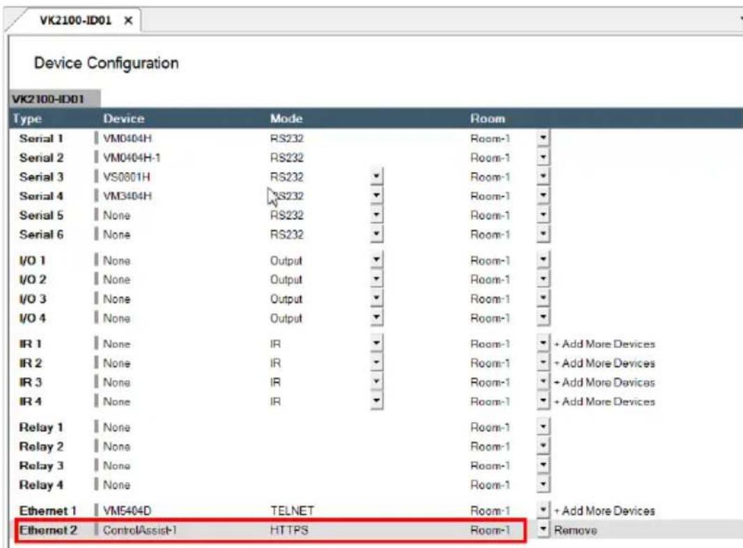
- Select the newly added device and configure the Properties settings on the right of the interface.
Hint: If you have more than one computers installed with ControlAssist, change the device name to distinguish these PCs.
For details on Properties settings, see Ethernet Device Properties, page 121.
Configuring a Control Interface
Example 1:
Follow the steps below to create a control interface that allows you to browse and play any file from the specified root folder (see page 277) in the target computer. You can follow the same logic for creating a media control page.
- In the Design tab, make sure your home page contains a presentation button and the Viewer contains a PowerPoint page.

- Configure the button to have it link to the PowerPoint page if pressed in the Viewer.
a) Click the presentation button.
b) Select Link and then double-click the PowerPoint page.

- Configure the PowerPoint page if you did not use a built-in Viewer template.
a) In the left sidebar, click PowerPoint.
b) In the PowerPoint page, right-click any blank spot and select PowerPoint Control Template. A pre-made screen is added.
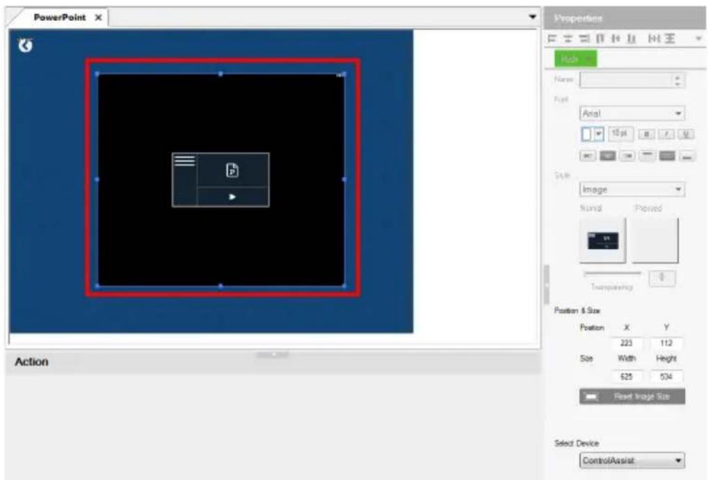
c) In the Properties column, use the Select Device drop-down menu to select the PC that stores the PowerPoint files you want to play.
Example 2:
Follow the steps below to create a quick access button for opening and playing a specific PowerPoint file. You can follow the same logic to create a button for opening and playing a specific media file.
![ATEN Configurator - [Computex 20LT053D.vkproj*] File Edit View Object Tools Windows Help 1 Project 2 Device 3 Design 4 Upload Controller Viewer iPad standby presentation conference Page1 TV standby presentation conference Presentation Select Search on Main TV 2a 2b Button Action Device RECO-1 Device RECO-1 Device RECO-1 Device RECO-1 Device RECO-1 Device RECO-1 Device RECO-1 Device RECO-1 Device RECO-1 Device RECO-1 Device RECO-1 Device RECO-1 Device RECO-1 Device RECO-1 Device RECO-1 设备 Link Set Flag Condition Charge Button State. Function [Media Control] Switch Mode mode * [Media Control] Switch Report mode * [Media Control] Next * [Media Control] Previous * [Media Control] Close * [Media Control] Open play list * [PowerPoint control] Open file * [PowerPoint control] Start Presentation * [PowerPoint control] End Presentation * [PowerPoint control] Close * [PowerPoint control] Go to Next slide. Commands [Control/Assist] or VK2100/IDE1 Ethernet (S) Control/Assist (PowerPoint cables) (O) [Control/Assist] or VK2100/IDE1 Ethernet (S) Control/Assist (PowerPoint cables) (S)](/content/2026/05/1091984/images/779470b11ae619b1c14502595c5e3b5f0226d5c029b5e70e5d14f41e76b2351d.jpg)
- Create an outlook for the interface.
a) In ATEN Configurator, click the Design tab.
b) Click Add Page and rename the page to "presentation".
c) Customize the interface and add control buttons using the Properties settings in the right-hand column. For details, see Configuring the Control Interface (Viewer), page 127.
- Define the action of each button. For example, for the PowerPoint button to open and start a slide show when pressed, do the following:
a) In the preview pane, click the PowerPoint button.
b) Select ControlAssist (LAN).
c) Double-click [PowerPoint] Open file and then [PowerPoint] Start presentation.
d) Configure the commands and arrange them in the order of execution.
Tip: The asterisk (*) at the end of a Function indicates that it requires configuration in the Commands column.
For details on supported control actions, see Supported PC Control Actions, page 286.
- From the Upload tab, deploy and back up the project to the controller. For details, see The Upload Tab, page 245.
Supported PC Control Actions
| Command Function | |
| Note: Commands indicated with an asterisk require configuration after being added to the Commands column in the Configurator. | |
| [Media Control]Note: The commands in this group apply to Windows Media Player only. | |
| Close Closes the player. | |
| Next Plays next in the playlist. | |
| Open file* Opens and plays the specified file in Windows Media Player. | |
| Open playlist* | Opens and plays the specified playlist in Windows Media Player. |
| Pause Pauses the playback. | |
| Play Plays the opened file in Windows Media Player. | |
| Previous Plays previous in the playlist. | |
| Set volume to* Sets the player to a specified volume. | |
| Stop Stops the playback. | |
| Switch to full screen mode* | Enables or disables the player to full-screen display. |
| Switch to mute mode* Enables or disables mute mode. | |
| Switch to repeat mode* Enables or disables repeated play. | |
| Volume* Adjusts the player's volume up or down. | |
| [PowerPoint Control] | |
| Open file* Opens the specified PowerPoint file. | |
| Start presentation | Starts the slide show of the specified PowerPoint file. |
| End presentation | Ends the slide show of the specified PowerPoint file. |
| Close Closes the opened PowerPoint file. | |
| Go to next slide* | Goes to the next slide. |
| Go to previous slide | Goes to the previous slide. |
| Go to slide | Goes to a specified slide number. |
| [System Control] | |
| Open file* Opens a specified file saved in the target computer. | |
| Open URL* | Opens a specified URL. |
| Run program* | Runs an application. |
| Shut down PC | Shuts down the computer. |
| Set volume* Adjusts the computer's volume. | |
| Execute Command Prompt* | Executes the specified command via Command Prompt. |
| Bring application to top* Keeps the window of the specified program on top of other windows that are open on the desktop. | |
| [Hotkey Control] | |
Create action Executes the associated hotkey(s) on the program that opens topmost on the computer desktop.For example, if you have “Ctrl + f” defined as the hotkey for extending a program to full screen in the program itself, to remotely simulate this action, you should have one Create action command associated with two Select key commands, one defined as “Ctrl”, and the other as “f”: 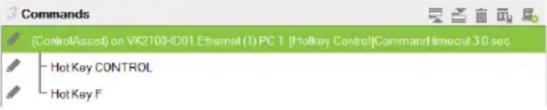 | |
| Select key* Use this command to specify the hotkey as defined in the target program. If the hotkey involves pressing two or more keys at the same time, you will have two or more Select key commands associated to one Create action command. See the example in the Create action command above. | |
Note: Adhere to the following guidelines when specifying file paths:
- Include the file name and file extension of the target file.
◆ Use double backward slashes between folder levels. - If the file path contains space, put the file path in double quotations.
- The following are examples of valid file paths:
"C:\ControlAssist\Presentation.pptx"
"C:\ControlAssist\Presentation Demo.pptx"
This Page Intentionally Left Blank
Chapter 7
ATEN Control System App
Overview
The ATEN Control System App is a platform that allows you to operate your control system using pre-made Viewers on mobile devices with an iOS, Android, or Windows platform.
Requirements
Make sure your mobile device uses a supported version of the mobile operating system listed below before installing the app.
| Mobile Operating System Supported Version | |
| iOS 10.0 or later | |
| Android 8.0 or later | |
| Windows 7 or later | |
Installing the App
To install the ATEN Control System App on a mobile device, do the following:
- From the mobile device, tap the App Store icon.
or Google Play - In the search box, type "aten control".
- Tap ATEN Control System, and then download and install the app.
- The ATEN Control System icon the icon to open the app.


Note: The button sound is enabled by default. To mute button sound, go to Settings of the mobile device, find ATEN Control app and disable the button sound setting.
Demo/Start Screen
When you open the ATEN Control System app for the first time, the demo/start screen appears:

flowchart
graph TD
    A["Start"] --> B["SYSTEM"]
    B --> C["FOR"]
    C --> D["NO"]
    D --> E["DEMO"]
    style A fill:#90EE90,stroke:#333
    style B fill:#90EE90,stroke:#333
    style C fill:#90EE90,stroke:#333
    style D fill:#90EE90,stroke:#333
    style E fill:#90EE90,stroke:#333
    note right of A: Control Without Complication
Tap Demo to try the ATEN Control System app. Tap Start to find a controller and download Viewers (see Overview, page 295).
Note: The default demo/start screen appears until a Viewer is downloaded to the Control System app. After a Viewer is downloaded, the default demo/start screen will reappear only if the app is reinstalled, which will also delete all Viewers.
The Demo page provides two sample Viewers. Tap either one to view the controls of different hardware devices.
To return to the demo/start page, tap Quit Demo at the top right corner.
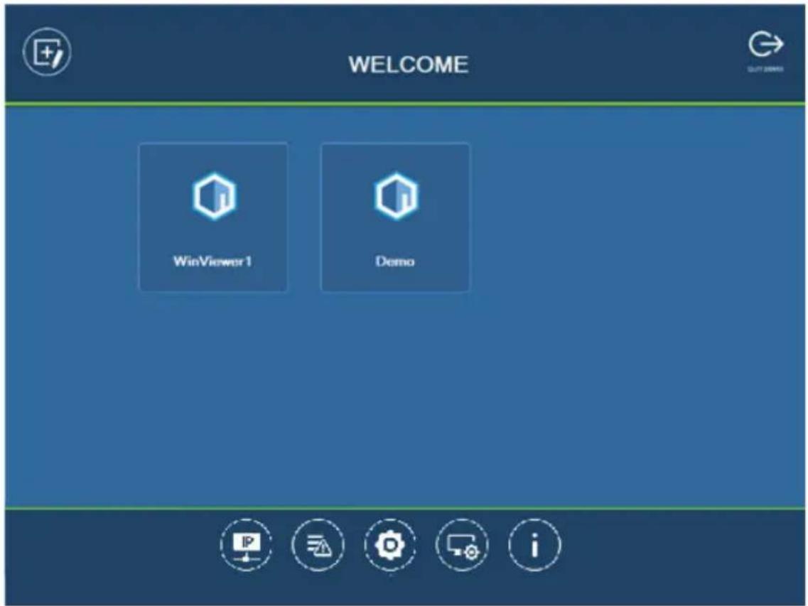
Select a Viewer or press any of the buttons on the Welcome page to demo the app. The first Viewer's name will depend on the OS of the device.
WinViewer1 / iPad / Android1

This demo shows a Conference call interface with controls for a Projector, Screen and Lighting. Tap any of the device icons to open each of the following control pages:

Demo
This demo shows different buttons that can be pressed to control the Projector, Lights, Video Wall and Camera. Tap the icons to view control pages for each device. Tap the Quit Demo icon to return to the previous page, or press on the background until the logout dialog appears.

Control Pages

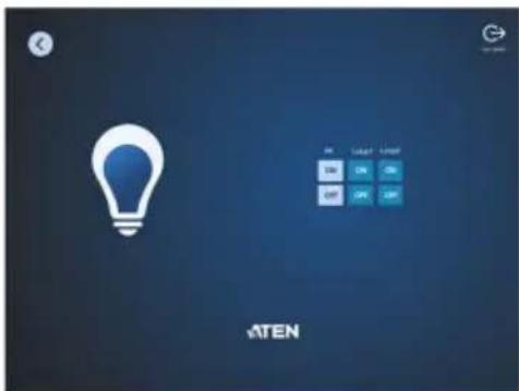


The images above show control pages for the Projector, Lights, Video Wall and Camera in Demo. Tap the Home icon in the lower left corner to return to the previous page, or press on the background until the logout dialog appears. To return to the demo/start page, tap Quit Demo at the top right corner.
Overview
Welcome (List of Viewers) Page
The Welcome screen is the home screen of the ATEN Control System app. It lists downloaded Viewers and provides administrative options. Tap a Viewer to open the controls for a room (see Configuring the Control Interface (Viewer), page 127), or use the administrative options listed below.

| Control Description | |
 | Manage Viewer – Use this page to add, update, and remove downloaded Viewers. See page 296 for details. |
 | Manage LAN Device – Use this page to access controller's web console or configure the network settings for controllers and the devices that they manage. See page 297 for details. |
 | Log Report – Use this page to lookup logs to troubleshoot connectivity issues. See page 302 for details. |
 | Preferences – Use this page to set a password for accessing the app or configure the app's usage settings. See page 303 for details. |
 | Settings – Use this page to access the system settings page of ATEN Touch Panel. This tab is only accessible when the Control System app is used on an ATEN Touch Panel. |
 | Information – This page provides information about the ATEN Control System's software version. See page 310 for details. |

Manage Viewer
The Manage Viewer page allows you to add, update, and remove downloaded Viewers. To download Viewers, tap Add Viewer.

| Control Description | |
 | Tap Add Viewer to download Viewers. See page 311 for details. |
 | Tap the Information icon to view the MAC Address, IP Address and Controller ID of the controller associated with the Viewer. |
| Update | Tap Update to connect to the controller and download an updated version of the Viewer. After the update, the “Downloaded Successfully” prompt will appear |
| Remove | Tap Remove to delete the Viewer. A dialog box will appear to confirm deletion of the Viewer.Tap Delete to remove the Viewer, or Cancel to cancel the deletion.Note: Viewers are only deleted on the mobile device, and will still be available on the controller. |
| Done Tap | Done to return to the Welcome page. |

Manage LAN Device
The Manage LAN Device page allows you to edit network settings for the controllers and LAN devices added in the Configurator software
(see Device Library, page 126).

| Control Description | |
 | Tap to expand controllers to view connected LAN devices. |
 | Tap to open the web GUI (Chapter 3, Web-based Configuration and Control). |
Depending on the LAN device you select, different options are available. Tap on a device to open the settings page. Use Edit to change settings, Apply to save or OK to exit.
Controller
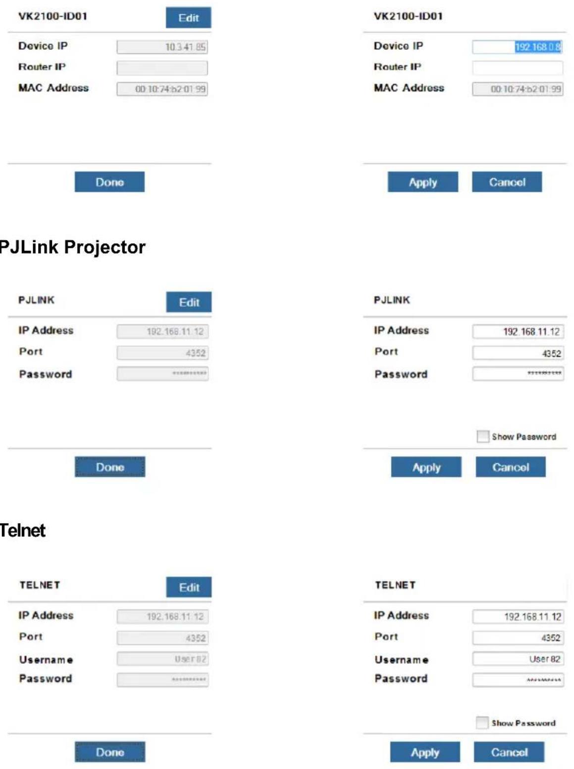
Telnet
ONVIF


TCP


UDP

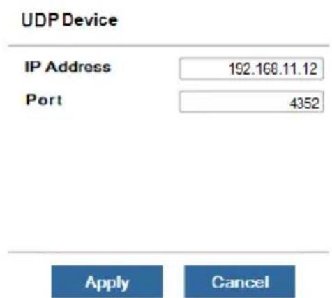
Simulating Viewer Controls with Demo Mode
You can preview Viewers and simulate control actions without connecting to a controller using the demo mode.
- To simulate controls of a target Viewer, download the Viewer file. For details, see Download Viewer, page 311.
Note: If you wish to use built-in Viewers, skip this step.
- Tap the ATEN Control app icon from your mobile device. This screen appears.
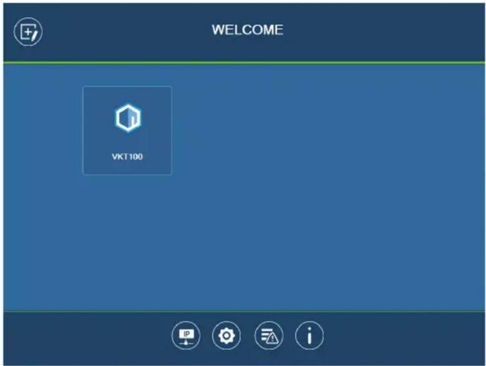
Note: If you have not downloaded any Viewers to the app, a Demo/Start page appears. Tap Demo to use built-in Viewers for the simulation.
- Tap Settings . The Preferences page appears.
- Tap Enable demo mode to select the setting and tap Set. Demo mode is immediately applied.
- Tap to return to the Welcome page.
-
Tap a Viewer to view and try out its control interface.
-
To close the Viewer, long tap any space on the mobile device and click OK in a pop-up dialog box.
- To disable demo mode, close the Viewer and then go to Settings to disable the demo mode setting.


Log Report
The Log Report page lists information and errors which can be used to troubleshoot issues. Tap and drag the list to scroll through the logs. Tap Back to exit.
![Log Report Latest report 2017-05-17 10:20:40:848 [00001022] Loading...](/content/2026/05/1091984/images/34b80a666cb2dcf3b82e88dabfdb47346dcaa8b506dc985f87766a7f7c9a61db.jpg)
| Control Description | |
 | Tap Save to save the log file. |
 | Tap Report History to view saved logs (see page 309). |
 | Tap Delete to delete the log information. |
 | Tap Back to exit. |

Preferences
The Preferences page provides settings for operation preferences of the Control System app, access to Room Booking System, and AppSwitcher.

General
- Seconds to press before the exit dialog appears: This sets the duration of idle time. When the app idles for the specified duration, an Exit dialog appears to check if the user wants to close the app.
Screen Mode
Note: This setting only takes effect on Viewer control pages.
- Screen saver: Select this option to start a screen saver when the mobile device has idled for the specified duration.
Screen lock: Select this option for the mobile device to lock the screen based on its related setting on the mobile device.
◆ Always on: Select this option to have the screen on all the time.
- Enable password protection: To restrict access to app settings and prevent unwanted configuration, enable password authentication for leaving the control pages.
- Allow keyboard usage when this app is in full screen: Enable this option to allow keyboard operation when the app is in full screen.
- Notify me when this app disconnects from the Internet: Select this option to notify the user when the app disconnects from the Internet.
- Connect to ATEN Control System devices based on the Manage Device IP list: Select this option for the app to identify and connect to controllers by IP address instead of the controller ID. This is useful when you create projects by duplication, in which case you do not need to reconfigure the controller ID in each project.
- Show alert messages for Ethernet devices managed by the controller (only applicable to the iOS version of the app): Enable this setting to receive status notifications for the managed Ethernet devices.
- Always open viewers in full screen (only applicable to the Windows version of the app): Enable this setting to open Viewers (i.e. control pages, for examples see page 292) in full screen.
- Show minimize, maximize, and close buttons (only applicable to the Windows version of the app): Enable this setting to show the minimize, maximize, and close buttons at the top-right corner of a Viewer (i.e. control page, for examples see page 292).
- Enable demo mode: Select this setting to allow viewing of the control pages within the Viewer (with no actual effects) when no controller is connected.
- Enable physical buttons on Viewer device (only applicable to VK330): To prevent access to physical buttons on the touch panel, disable this setting.
- Use fast connection: Enable this setting for the Viewer to connect to its designated controller more quickly by skipping the checkup of extension boxes to the controller.
Receiving Room Usage Notifications from ATEN Room Booking System
You can receive notifications of room usage including check-in, check-out, and reservation extension on ATEN Touch Panel / Android mobile device as soon as the action is made.
This feature also requires management and configuration of ATEN Unizon. For more information, see ATEN Unizon User Manual. The Access to RBS control setting merely allows the device to be able to receive notifications from ATEN Unizon.
Allowing Room Usage Notifications
- Go to Preferences > Advanced page, enable Access to RBS control to allow ATEN Unizon to send notifications to the mobile device.
- (Optional) Enable/disable notification sound.
- Tap Set to save the settings. The RBS control icon appears.
Remote RBS Control
You can check in, check out, or extend meeting reservation using ATEN Touch Panel / Android mobile device.
To allow these remote actions:
- Go to Preferences > Advanced.
- Enable the Access to RBS Control setting and tap Set.
The RBS control icon appears.
AppSwitcher
You can maximize the usage of an ATEN Touch Panel (VK330) using AppSwitcher which allows you to install multiple apps (ATEN or third-party apps) on the Touch Panel and to switch apps should your need changes.
Adding Apps to ATEN Touch Panel And AppSwitcher
Follow the procedure below to install apps to an ATEN Touch Panel and to add them to AppSwitcher to make them available for switching.
- Go to Preferences > Advanced, enable the Access to app switch setting.

-
Tap Add App to install an app to the mobile device.
-
Tap C to refresh the list. The installed apps appear on the list.
-
To make an app available for switching, tap the app to add it to AppSwitcher. Apps added to AppSwitcher are marked with black icon. Tap again to unselect. You can add multiple apps to AppSwitcher.
-
Tap Set. The AppSwitcher control icon 📋 appears.
-
To uninstall an app, tap Remove App.
Using AppSwitcher
You can switch among the installed and added apps using AppSwitcher.
- On your Viewer, find the AppSwitcher control
If you can not find the control, go to Preferences > Advanced page, enable the Access to app switch setting, and tap Set. The AppSwitcher control should appear.
- Tap . A list of available apps appear.

- Tap from the list to switch the control to the selected app. For example:

Note: If the app you wish to use is not in the list, tap Go to Preferences, and then make sure the app is installed and added to AppSwitcher. For detailed instructions, see Adding Apps to the Device and AppSwitcher, page 306.
- To return to the previous control page, tap Back to main control.

Report History
When you tap Report History, you can view and export logs. Saved log files are listed by date in the left column. Tap a log file to view it in the window to the right. Tap and drag the list to scroll through the logs. Tap Back to exit.
![Reports Apr 27, 2017 20170427_2.vklog 20170427 11:25 saved 20170427_1.vklog 20170427 11:20 saved Apr 26, 2017 20170426_2.vklog 20170426 15:42 saved 20170426_1.vklog 20170426 15:16 saved 2017-04-26 15:16:25.854 [20020903] Receive Quick Action FeedBack 2017-04-26 15:16:25.883 [00020112] Action Feedback: 4261415601 enable 2017-04-26 15:16:26.009 [00020006] Send Quick Action Request to (fe000ab1_press) 2017-04-26 15:16:26.009 [00020910] Send Quick Command 10.3.41.85 Success. 2017-04-26 15:16:26.157 [20020903] Receive Quick Action FeedBack 2017-04-26 15:16:26.203 [00020112] Action Feedback: 4261415601 enable 2017-04-26 15:16:26.322 [00020006] Send Quick Action Request to (fe000ab1_press) 2017-04-26 15:16:26.322 [00020910] Send Quick Command 10.3.41.85 Success. 2017-04-26 15:16:26.491 [20020903] Receive Quick Action FeedBack 2017-04-26 15:16:26.492 [00020112] Action Feedback: 4261415601 enable](/content/2026/05/1091984/images/a2f68c65a6f38cc9010e95bb72d6a3dd3c2acdfd0877bb1624aa836fc3079980.jpg)

Tap Export to send the log as an e-mail attachment.

Information
The Information page displays the ATEN Control System's version.


Download Viewer
The Download Viewer page allows you to search for controllers and download Viewers. This page is accessed from Welcome→Manage Viewer→Add Viewer.

| Control Description | |
| Search by IP Address | Tap to enter a controller's IP address, then tap the Search icon to find it. When controllers are found on the network, they are listed in the Add Viewer box.A Search History drop-down menu will appear for previously searched IP addresses. |
| Auto Search Auto S | Search allows you to search for controllers without specifying an IP address. The controller must be powered on and connected to the same local network. |
| Add Viewer This panel lists the controllers that have been found on the network. Each controller lists Viewers that can be downloaded to the mobile device. To upload Viewers to a controller, see The Upload Tab, page 245. | |
| Back Icon Back returns you to the Welcome page. | |
| Download After you | select the Viewers you want to download, click Download to start the process. |
Downloading Viewers
When controllers are found, they appear in the Add Viewer panel. Check the boxes of the Viewers you would like to download, then tap Download.

| Control Description | |
| Add Viewer The | main window lists the controllers that have been found on the network. Under each controller is a list of Viewers with a check box.Use the check boxes to select the Viewers you want to download, then clickDownload.If the Lock icon appears, you will be prompted to enter the access key.After Viewers download, the “Downloaded Successfully” prompt appears. TapDoneto return to the Welcome page where the Viewers will be listed.Note:After you download a Viewers to the mobile device, the default Welcome screen no longer appears. |
| Access Key | When the a Viewers requires an access key a window appears prompting you to enter the key. Enter the correct access key and then clickOKto download the Viewers from the controller. To set the access key, seeThe Upload Tab, page 245. |
 | Tap the Information icon to view theIP Address, MAC AddressandLicenseinformation of the controller. The license information provides the total number of licenses available and the number in use. |
Appendix
Safety Instructions
General
- Read all of these instructions. Save them for future reference.
◆ Follow all warnings and instructions marked on the device. - This product is for indoor use only.
- Do not place the device on any unstable surface (cart, stand, table, etc.). If the device falls, serious damage will result.
- Caution: Risk of explosion if the battery is replaced by an incorrect type. Always dispose of used batteries according to the proper instructions.
♦ Do not use the device near water. - Do not place the device near, or over, radiators or heat registers.
- The device cabinet is provided with slots and openings to allow for adequate ventilation. To ensure reliable operation, and to protect against overheating, these openings must never be blocked or covered.
- The device should never be placed on a soft surface (bed, sofa, rug, etc.) as this will block its ventilation openings. Likewise, the device should not be placed in a built-in enclosure unless adequate ventilation has been provided.
- Never spill liquid of any kind on the device.
- Unplug the device from the wall outlet before cleaning. Do not use liquid or aerosol cleaners. Use a damp cloth for cleaning.
- The device should be operated from the type of power source indicated on the marking label. If you are not sure of the type of power available, consult your dealer or local power company.
- To prevent damage to your installation it is important that all devices are properly grounded.
- Do not allow anything to rest on the power cord or cables. Route the power cord and cables so that they cannot be stepped on or tripped over.
- Position system cables and power cables carefully; Be sure that nothing rests on any cables.
-
Never push objects of any kind into or through cabinet slots. They may touch dangerous voltage points or short out parts resulting in a risk of fire or electrical shock.
-
Do not attempt to service the device yourself. Refer all servicing to qualified service personnel.
-
If the following conditions occur, unplug the device from the wall outlet and bring it to qualified service personnel for repair.
-
The power cord or plug has become damaged or frayed.
♦ Liquid has been spilled into the device. - The device has been exposed to rain or water.
- The device has been dropped, or the cabinet has been damaged.
- The device exhibits a distinct change in performance, indicating a need for service.
- The device does not operate normally when the operating instructions are followed.
- Only adjust those controls that are covered in the operating instructions. Improper adjustment of other controls may result in damage that will require extensive work by a qualified technician to repair.
- Avoid circuit overloads. Before connecting equipment to a circuit, know the power supply’s limit and never exceed it. Always review the electrical specifications of a circuit to ensure that you are not creating a dangerous condition or that one doesn’t already exist. Circuit overloads can cause a fire and destroy equipment.
Rack Mount
- Before working on the rack, make sure that the stabilizers are secured to the rack, extended to the floor, and that the full weight of the rack rests on the floor. Install front and side stabilizers on a single rack or front stabilizers for joined multiple racks before working on the rack.
- Always load the rack from the bottom up, and load the heaviest item in the rack first.
- Make sure that the rack is level and stable before extending a device from the rack.
- Use caution when pressing the device rail release latches and sliding a device into or out of a rack; the slide rails can pinch your fingers.
- After a device is inserted into the rack, carefully extend the rail into a locking position, and then slide the device into the rack.
- Do not overload the AC supply branch circuit that provides power to the rack. The total rack load should not exceed 80 percent of the branch circuit rating.
- Make sure that all equipment used on the rack – including power strips and other electrical connectors – is properly grounded.
- Ensure that proper airflow is provided to devices in the rack.
- Ensure that the operating ambient temperature of the rack environment does not exceed the maximum ambient temperature specified for the equipment by the manufacturer.
- Do not step on or stand on any device when servicing other devices in a rack.
Technical Support
International
- For online technical support – including troubleshooting, documentation, and software updates: http://eservice.aten.com
- For telephone support, see Telephone Support, page iv:
North America
| Email Support support@aten-usa.com | ||
| Online Technical Support | Troubleshooting Documentation Software Updates | https://eservice.aten.com |
| Telephone Support 1-888-999-ATEN | ext 4988 | |
When you contact us, please have the following information ready beforehand:
◆ Product model number, serial number, and date of purchase.
- Your computer configuration, including operating system, revision level, expansion cards, and software.
◆ Any error messages displayed at the time the error occurred.
- The sequence of operations that led up to the error.
◆ Any other information you feel may be of help.
Specifications
| VK0100 VK0200 | ||
| Interface | ||
| Keypad Layout Up to 14 | layout variations using 4 ~ 8 buttons | Up to 125 layout variations using 6 ~ 12 buttons |
| Serial • 2 x Bidirectional | RS-232 Port (2 x 3-Pole Terminal Block Connector)Baud Rate: 300 to 115200 (default: 9600)Data Bit: 8 (default) or 7Stop Bit: 1 (default) or 2Parity: None (default), even or odd | |
| Relay • 2 x Relay Channel | el (2 x 2-Pole Terminal Block Connector)Normally open, isolated RelaysContact Rating: Max 24 VDC, 1A | |
| Digital Input • 1 x Digital | Input Channel (1 x 2-Pole Terminal Block Connector);VDC Mode- Input Voltage Range: 0 to 5 V DC- Programmable Range: 1 to 5 V DCDry Contact Mode-Pull-up 2k ohms to + 5 V DC | |
| Ethernet • 1 x RJ-45 Female | Male, 10/100Base-TSupported Protocol: ARP, ICMP, TCP/IP, DHCP, HTTPS, SSHDHCP-enabled. Default IP settings (IP address 192.168.0.60, subnet mask 255.255.255.0) will be automatically applied if no IP address is assigned within 30 seconds of connecting to the network. | |
| Switches & Buttons | ||
| Controller ID Switch 1 x | 16-segment Switch | |
| Reset Button 1 x Semi-recessed Pushbutton | ||
| Power | ||
| Power Consumption DC | 5V : 1.1W : 5 BTU/hPoE : 1.375 W : 6 BTU/h | DC 5V : 1.15W : 5 BTU/hPoE : 1.44 W / 7 BTU/h |
| VK0100 VK0200 |
Note:
- The measurement in Watts indicates the typical power consumption of the device with no external loading.
- The measurement in BTU/h indicates the power consumption of the device when it is fully loaded.
| Environmental | ||
| Operating Temperature | 0 – 50 °C | |
| Storage Temperature –20 – 60 °C | ||
| Humidity 0 - 80% RH, Non-Condensing | ||
| Physical Properties | ||
| Housing Plastic | ||
| Weight 0.16 kg (0.35 lb) | 0.19 kg (0.42 lb) | |
| Dimensions 11.63 x 7.06 | 6 x 4.84 cm(4.58 x 2.78 x 1.91 in) | 8.32 x 14.76 x 4.84 cm(3.28 x 5.81 x 1.91 in) |
| Mobile Control License | ||
| No. of free licenses 0 | ||
| Max. no. of paid licenses | 10 | |
| Note: Each time a mobile device connects to an ATEN Control Pad for remote control, one license on the Control Pad will be occupied. To purchase and add additional licenses to your Control Pad, contact your local sales representative for more information. | ||
| VK108US VK112EU | ||
| Interface | ||
| Keypad Layout Up to 14 layout variations using 4 ~ 8 buttons | Up to 125 layout variations using 6 ~ 12 buttons | |
| Ethernet • 1 x RJ-45 Female, 10/100Base-T• Supported Protocol: ARP, ICMP, TCP/IP, DHCP, HTTPS• DHCP-enabled. Default IP settings (IP address 192.168.0.60, subnet mask 255.255.255.0) will be automatically applied if no IP address is assigned within 30 seconds of connecting to the network. | ||
| Switches & Buttons | ||
| Controller ID Switch 1 x 16-segment switch | ||
| Keypad ID Switch 1 x 8-segment switch | ||
| Reset Button | ||
| 1 x semi-recessed pushbutton | ||
| Power | ||
| Power Consumption DC 5V : 1.25W : 6 BTU/hDC 48V : 1.58W : 7BTU/h | DC 5V : 1.25W : 6 BTU/hPoE: 1.56W : 7BTU/h | |
| Note:• The measurement in Watts indicates the typical power consumption of the device with no external loading.• The measurement in BTU/h indicates the power consumption of the device when it is fully loaded. | ||
| Environmental | ||
| Operating Temperature 0 - 50 °C | ||
| Storage Temperature -20 - 60 °C | ||
| Humidity 0 - 80% RH, Non-Condensing | ||
| Physical Properties | ||
| Housing Plastic | ||
| Weight 0.13 kg (0.29 lb) 0.17 kg (0.37 lb) | ||
| Device Dimensions | 11.63 x 7.06 x 4.84 cm(4.58 x 2.78 x 1.91 in) | 8.32 x 14.76 x 4.80 cm(3.28 x 5.81 x 1.89 in) |
| Faceplate Dimensions | 11.92 x 7.42 x 0.92 cm(4.69 x 2.92 x 0.36 in) | 8.62 x 15.12 x 0.92 cm(3.39 x 5.95 x 0.36 in) |
| VK1100A | |
| Memory | |
| SDRAM 512 MB | |
| Flash 8 GB | |
| Interfaces | |
| Serial 1 x Programmable | bidirectionalRS-232/422/485 port (1 x 5-pole terminal block connector, configurable via pin assignments)◆ Baud Rate: 300 to 115200 (default: 9600)◆ Data Bit: 8 (default) or 7◆ Stop Bit: 1 (default) or 2◆ Parity: None (default), Even, or Odd◆ Flow Control: None (default) or RTS/CTS1 x bidirectional RS-232 port(1 x 3-pole terminal block connector)◆ Baud Rate: 300 ~ 115200 (default: 9600)◆ Data Bit: 8 (default) or 7◆ Stop Bit: 1 (default) or 2◆ Parity: None (default), Even, or Odd |
| IR/Serial 2 x Programmable | IR / UnidirectionalRS-232 Ports (2 x 2-Pole Terminal Block Connectors) |
| IR:◆ Carrier Frequency: 10 ~ 455 kHz◆ Signal Level: TTL (0 ~ 5 V DC) | |
| Serial:◆ Baud Rate: 300 ~ 115200 (default: 9600)◆ Data Bit: 8 (default) or 7◆ Stop Bit: 1 (default) or 2◆ Parity: None (default), Even, or Odd◆ Signal Level: TTL (0 ~ 5 V DC) | |
VK1100A
| I/O 2 x Programmable Digital Input / Output Channels(1 x 3-Pole Terminal Block Connector) | |
| Relay | 4 x Relay Channels (2 x 4-Pole Terminal Block Connector)Normally Open, Isolated RelaysContact Rating: Max 24 V DC, 2 A |
| V DC | 1 x 12 V DC Output Port (1 x 2-Pole Terminal Block Connector)Power Supply: 12 V DC, 1 A Max |
| Ethernet | 2 x RJ-45 Female, 10/100/1000 Base-TSupported protocol: ARP, ICMP, TCP/IP, DHCP, HTTPS, SSHDHCP-enabled. Default IP settings (IP address 192.168.0.60 / 192.168.1.60 for Control LAN / LAN, subnet mask 255.255.255.0) will be automatically applied if no IP address is assigned within 30 seconds of connecting to the network. |
| USB 1 x USB Type-A | |
| Switches | |
| Power 1 x on/off Switch | |
| IR Learning | |
| 1 x IR Receiver LED | |
| Reset Button | |
| 1 x Semi-recessed pushbutton | |
| VK1100A | |
| Power | |
| Power Consumption AC | 110 V : 4.3 W : 82 BTU/hAC 220 V : 4.5 W : 83 BTU/h |
| Note:◆ The measurement in Watts indicates the typical power consumption of the device with no external loading.◆ The measurement in BTU/h indicates the power consumption of the device when it is fully loaded. | |
| Maximum Input Power Rating | internal power: 100 - 240 V AC, 50 - 60 Hz |
| Environmental | |
| Operating Temperature 0 | -50 °C |
| Storage Temperature -20 | -60 °C |
| Humidity 0 - 80% RH, Non-condensing | |
| Physical Properties | |
| Housing Metal | |
| Weight 1.19 kg | |
| Dimensions (L x W x H) | 21.50 x 16.23 x 4.18 cm |
| Mobile Control License | |
| No. of free licenses 2 | |
| Max. no. of licenses 16 | |
| Note: The ATEN Control Box Gen. 2 comes with two free licenses which are stored in the device itself. Each time a mobile device connects to an ATEN Control Box Gen. 2 for remote control, one license on the Control Box Gen. 2 will be occupied. To purchase and add additional licenses to your Control Box, contact your local sales representative for more information. | |
| VK1200 | |
| System | |
| SD RAM 1 GB | |
| Flash Memory 8 GB | |
| Interface | |
| Serial 1 x Programmable bidirectionalRS-232/422/485 port (1 x 5-pole terminal block connector)1 x Programmable bidirectional RS-232 port(1 x 3-pole terminal block connector)◆ Baud Rate: 300 ~ 115200 (default: 9600)◆ Data Bit: 8 (default) or 7◆ Stop Bit: 1 (default) or 2◆ Parity: None (default), Even, or Odd◆ Flow Control: None (default) RTS/CTS (for 5-pole terminal block) | |
| IR/Serial 2 x Programmable IR / UnidirectionalRS-232 Ports (2 x 2-Pole Terminal Block Connectors) | |
| I/O 2 x Programmable Digital Input / Output Channels(1 x 3-Pole Terminal Block Connector) | |
| Relay | 4 x Relay Channels (2 x 4-Pole Terminal Block Connector)Normally Open, Isolated RelaysContact Rating: Max 24 V DC, 2 A |
| V DC | 1 x 12 V DC Output Port (1 x 2-Pole Terminal Block Connectors)Power Supply: 12 V DC, 1 A Max |
| Ethernet | 2 x RJ-45 Female, 10/100/1000 Base-TSupported protocol: ARP, ICMP, TCP/IP, DHCP, HTTPS, SSHDHCP-enabled. Default IP settings (IP address 192.168.0.60 / 192.168.1.60 for Control LAN / LAN, subnet mask 255.255.255.0) will be automatically applied if no IP address is assigned within 30 seconds of connecting to the network. |
| USB 1 x USB Type-A | |
| LCD Panel | |
| Size 1.6" | |
| LCM Display 64 x 128 resolution | |
| LCM Setting 3 x Pushbuttons (Up, Down, Enter) | |
| Switches | |
| Power 1 x on/off Switch | |
| IR Learning | |
VK1200
1 x IR Receiver LED
Reset Button
1 x Semi-recessed pushbutton
Power
| Power Consumption AC 1 | 10 V : 4.7 W : 81 BTU/h |
| AC 220 V : 4.5 W : 81 BTU/h |
Note:
- The measurement in Watts indicates the typical power consumption of the device with no external loading.
- The measurement in BTU/h indicates the power consumption of the device when it is fully loaded.
| Maximum Input Power Rating | internal power: 100 - 240 V AC, 50 - 60 Hz |
Environmental
Operating Temperature 0–50 °C
Storage Temperature -20-60 °C
Humidity 0 – 80% RH, Non-condensing
Physical Properties
Housing Metal
Weight 1.23 kg
Dimensions (L x W x H) 20.00 x 16.41 x 4.40 cm
Mobile Control License
No, of free licenses 2
Max. no. of licenses 32
Note: The ATEN Control Box comes with two free licenses which are stored in the device itself. Each time a mobile device connects to an ATEN Control Box for remote control, one license on the Control Box will be occupied. To purchase and add additional licenses to your Control Box, contact your local sales representative for more information.
| VK2200 | |
| System | |
| SDRAM 2 GB | |
| Flash Memory 8 GB | |
| Interface | |
| Serial 2 x Bidirectional RS-232/422/485 Ports(2 x 5-Pole Terminal Block Connectors)◆ Baud Rate: 300 ~ 115200 (default: 9600)◆ Data Bit: 8 (default) or 7◆ Stop Bit: 1 (default) or 2◆ Parity: None (default), Even or Odd◆ Flow Control: None (default) or RTS/CTS6 x Programmable Bidirectional RS-232 Ports(6 x 3-Pole Terminal Block Connector)◆ Baud Rate: 300 ~ 115200 (default: 9600)◆ Data Bit: 8 (default) or 7◆ Stop Bit: 1 (default) or 2◆ Parity: None (default), Even or Odd | |
| IR/Serial 8 x Programmable IR / Unidirectional RS-232Ports (4 x 4-Pole Terminal Block Connectors) | |
VK2200
| I/O 8 x Programmable Digital Input / OutputChannels (2 x 5-Pole Terminal Block Connectors) | |
| Relay | 8 x Relay Channels (4 x 4-Pole Terminal Block Connector)Normally Open, Isolated RelaysContact Rating: Max 24 V DC, 2 A |
| V DC | 4 x 12 V DC Output Ports (2 x 4-Pole Terminal Block Connectors)Power Supply: 12 V DC, 2 A Max (Shared By 4 Ports) |
| Ethernet | 2 x RJ-45 Female, 10/100/1000 Base-TSupported protocol: ARP, ICMP, TCP/IP, DHCP, HTTPS, SSHDHCP-enabled. Default IP settings (IP address 192.168.0.60 / 192.168.1.60 for Control LAN / LAN, subnet mask 255.255.255.0) will be automatically applied if no IP address is assigned within 30 seconds of connecting to the network. |
| USB 1 x USB Type-A | |
| LCD Panel | |
| Size 1.6" | |
| LCM Display 64 x 128 resolution | |
| LCM Setting 3 x Pushbuttons (Up, Down, Enter) | |
| Switches | |
| Power 1 x on/off switch | |
| IR Learning | |
| VK2200 | |
| 1 x IR Receiver LED | |
| Reset Button | |
| 1 x Semi-recessed pushbutton | |
| Power | |
| Power Consumption AC 1 | 10 V : 5.7 W : 139 BTU/hAC 220 V : 6.8 W : 144 BTU/h |
| Note:The measurement in Watts indicates the typical power consumption of the device with no external loading.The measurement in BTU/h indicates the power consumption of the device when it is fully loaded. | |
| Max. Input Power Rating Internal power: 100 - 240 V AC, 50 - 60 Hz | |
| Environmental | |
| Operating Temperature 0 – 50 °C | |
| Storage Temperature -20 – 60 °C | |
| Humidity 0 – 80% RH, Non-condensing | |
| Physical Properties | |
| Housing Metal | |
| Weight 2.62 kg | |
| Dimensions (L x W x H) 43 | .24 x 16.32 x 4.40 cm |
| Mobile Control License | |
| No, of free licenses 2 | |
| Max. no. of licenses 32 | |
| Note: The ATEN Control Box comes with two free licenses which are stored in the device itself. Each time a mobile device connects to an ATEN Control Box for remote control, one license on the Control Box will be occupied. To purchase and add additional licenses to your ATEN Control Box, contact your local sales representative for more information. | |
| VK320 | |
| Processor | |
| Quad-core | |
| Memory | |
| SDRAM 2GB | |
| Flash 32GB | |
| Panel | |
| Display Type IPS-LCD | |
| Size 8" | |
| Touch Screen Capacitive | |
| Resolution 1280 x 800 | |
| Aspect Ratio 16:10 | |
| Color Depth 8 bit | |
| Contrast Ratio 800:1 | |
| Backlight LCD | |
| Viewing Angle ±85° (H), ±85° (V) | |
| Luminance | 300 cd/m2 |
| Interfaces | |
| Ethernet 1 x RJ-45 Female, 10/100 BaseT | |
| USB 1 x USB Type-C | |
| Power | |
| Power over Ethernet (PoE) | 802.3 at PoE+ |
| Power Consumption | DC12V : 12W : 40.95 BTU/hPoE: 14.1W : 4801 BTU/h |
Note:
- The measurement in Watts indicates the typical power consumption of the device with no external loading.
- The measurement in BTU/h indicates the power consumption of the device when it is fully loaded.
Environmental
| VK320 | |
| Operating Temperature | 0–40 °C |
| Storage Temperature | -10–55 °C |
| Humidity 10–75% RH, Non-condensing | |
| Physical Properties | |
| Housing Plastic | |
| Weight 0.33 kg (0.73 lb) | |
| Dimensions (L x W x H) | 20.01 x 12.46 x 3.77 cm (7.88 x 4.91 x 1.48 in.) |
| VK330 | |
| Processor | |
| Quad-core | |
| Memory | |
| SDRAM 2 GB | |
| Flash 16 GB | |
| Panel Specifications | |
| Display Type TFT-LCD | |
| Size 10.1" | |
| Touch Screen Capacitive | |
| Resolution 1280 x 800 | |
| Aspect Ratio 16:10 | |
| Color Depth 8 bit | |
| Contrast Ratio 800:1 | |
| Backlight LED | |
| Viewing Angle ±85° (H), ±85° (V) | |
| Luminance 500 cd/m2 | |
| Interfaces | |
| Ethernet 1 x RJ-45 Female, 10/ | 100/1000 BaseT |
| USB | 1 x USB Type-A |
| Power | |
| Power over Ethernet (PoE) | 802.3 at PoE+ |
| Power Consumption | DC 12V : 12.8W :43.65 BTU/hPoE:14W:47.77BTU |
Note:
- The measurement in Watts indicates the typical power consumption of the device with no external loading.
- The measurement in BTU/h indicates the power consumption of the device when it is fully loaded.
| Environmental | |
| Operating Temperature | 0–40 °C |
| Storage Temperature | -10–55 °C |
| VK330 | |
| Humidity 10–80% RH, Non-condensing | |
| Physical Properties | |
| Housing ABS + PC | |
| Weight 0.62 kg (1.37 lb) | |
| Dimensions (L x W x H) 25.22 x 17.78 x 2.45 cm (9.93 x 7 x 0.96 in.) | |
| VK401 | |
| Mode of Operation (Frequency) | |
| 13.56 MHz | |
| Interface | |
| Connector Type Pogo pin | |
| Industrial Protocols | |
| ISO 14443A/B, ISO 15693, Mifare, Felica (Card UID) | |
| Sensing Distance | |
| Up to 30 mm (depends on the tag type) | |
| Environmental | |
| Operational Temperature 0 – 40 °C | |
| Physical Properties | |
| Housing Plastic | |
| Weight 0.03 kg (0.08 lb) | |
| Dimensions (L x W x H) 5.60 x | 7.00 x 2.33 cm |
VK224
Interfaces
Serial 4 x programmable, bi-directional RS-232/422/485
ports (4 x DB9 Male Connector, configurable via pin assignments)
◆ Baud Rate: 300 to 115200 (default: 9600)
◆ Data Bit: 8 (default) or 7
♦ Stop Bit: 1 (default) or 2
♦ Parity: None (default), Even or Odd
◆ Flow Control: None (default) RTS/CTS
RS-232
Pin 2: RX
Pin 3: TX
Pin 5: GND
Pin 7: RTS
Pin 8: CTS
RS-422
◆ Pin 1: RX-
Pin 2: RX+
Pin 3: TX+
Pin 4: TX-
Pin 5: GND
RS-485
Pin 3: D+
Pin 4: D-
◆ Pin 5: GND*
Note: A ground terminal connection is recommended but not required.
Ethernet
◆ 1 x RJ-45 Female, 10/100Base-T
◆ Supported Protocol: ARP, ICMP, TCP/IP, DHCP, HTTPS, SSH
DHCP-enabled. Default IP settings (IP address 192.168.0.60, subnet mask 255.255.255.0) will be automatically applied if no IP address is assigned within 30 seconds of connecting to the network.
| VK224 | |
| Switches | |
| Controller ID 1 x 16-segment Switch | |
| Expansion Box ID 1 x 8-segment Switch | |
| Reset Button | |
| 1 x Semi-recessed Pushbutton | |
| USB | |
| 1 x USB Type A | |
| Power Consumption |
DC5V:3.8W:28BTU/h; DC48V:4.75W:33BTU/h
Note:
- The measurement in Watts indicates the typical power consumption of the device with no external loading.
- The measurement in BTU/h indicates the power consumption of the device when it is fully loaded.
| Environmental | |
| Operating Temperature | 0–50 °C |
| Storage Temperature -20 | -60 °C |
| Humidity 0–80% RH, Non-condensing | |
| Physical Properties | |
| Housing Metal | |
| Metal 0.45 kg (0.99 lb) | |
| Dimensions (L x W x H) | 13.00 x 7.58 x 4.20 cm (5.12 x 2.98 x 1.65 in.) |
| VK236 | |
| Interfaces | |
| IR/Serial 6 x Programmable | IR / Uni-directional RS-232 Port6 x 2-Pole Terminal Block ConnectorIR: TTL level (0 to 5 V)Carrier Frequency: 10KHz~455KHz;Serial: Uni-directional RS-232 (+ - 5 V)Baud Rate: 300 to 115200 (default: 9600)Data Bit: 8 (default) or 7Stop Bit: 1 (default) or 2Parity: None (default), Even or Odd |
| Ethernet | 1 x RJ-45 Female, 10/100Base-TSupported Protocol: ARP, ICMP, TCP/IP, DHCP, HTTPS, SSHDHCP-enabled. Default IP settings (IP address 192.168.0.60, subnet mask 255.255.255.0) will be automatically applied if no IP address is assigned within 30 seconds of connecting to the network. |
| Switches | |
| Controller ID 1 x 16-segment Switch | |
| Expansion Box ID 1 x 8-segment Switch | |
| Reset Button | |
| 1 x Semi-recessed Pushbutton | |
| USB | |
| 1 x USB Type A (firmware upgrades only) | |
| Power Consumption | |
| DC5V:1.31W:17BTU/h;DC48V:1.64W:18BTU/h | |
| Note:The measurement in Watts indicates the typical power consumption of the device with no external loading.The measurement in BTU/h indicates the power consumption of the device when it is fully loaded. | |
| Environmental | |
| Operating Temperature 0–50 °C | |
| Storage Temperature -20–60 °C | |
| Humidity 0–80% RH, Non-condensing | |
| Physical Properties | |
| Housing Metal | |
| Metal 0.45 kg (0.99 lb) | |
| Dimensions (L x W x H) 1 | 3.00 x 7.58 x 4.20 cm (5.12 x 2.98 x 1.65 in.) |
| VK248 | |
| Interfaces | |
| Relay | ♦ 8 normally open relays (8 x 2-pole terminal block)♦ Contact Rating: Max 24 VDC, 2A |
| Ethernet | ♦ 1 x RJ-45 Female, 10/100Base-T♦ Supported Protocol: ARP, ICMP, TCP/IP, DHCP, HTTPS, SSH♦ DHCP-enabled. Default IP settings (IP address 192.168.0.60, subnet mask 255.255.255.0) will be automatically applied if no IP address is assigned within 30 seconds of connecting to the network. |
| Switches | |
| Controller ID 1 x 16-segment Switch | |
| Expansion Box ID 1 x 8-segment Switch | |
| Reset Button | |
| 1 x Semi-recessed Pushbutton | |
| USB | |
| 1 x USB Type A (firmware upgrades only) | |
| Power Consumption | |
VK248
DC5V:2.82W:24BTU/h;
DC48V:3.53W:27BTU/h
Note:
- The measurement in Watts indicates the typical power consumption of the device with no external loading.
- The measurement in BTU/h indicates the power consumption of the device when it is fully loaded.
| Environmental | |
| Operating Temperature 0 | -50 °C |
| Storage Temperature -20 | -60 °C |
| Humidity 0–80% RH, Non | -condensing |
| Power Output | |
| 12 VDC, 300mA | |
| Physical Properties | |
| Housing Metal | |
| Metal 0.65 kg (1.43 lb) | |
| Dimensions (L x W x H) 2 | 0.00 x 7.58 x 4.20 cm (7.87 x 2.98 x 1.65 in.) |
| VK258 | |
| Interfaces | |
| Relay | ◆ 8 x Programmable Digital Input / Output Channel◆ Digital Input◆ VDC ModeInput Voltage Range: 0 to 24 VDCProgrammable Range: 1 to 24 VDC◆ Dry Contact ModePull-up 2k ohms to +12 VDC◆ Digital Output: 300 mA sink from 24 VDC |
| Ethernet | ◆ 1 x RJ-45 Female, 10/100Base-T◆ Supported Protocol: ARP, ICMP, TCP/IP, DHCP, HTTPS, SSH◆ DHCP-enabled. Default IP settings (IP address 192.168.0.60, subnet mask 255.255.255.0) will be automatically applied if no IP address is assigned within 30 seconds of connecting to the network. |
| Switches | |
| Controller ID 1 x 16-segment Switch | |
| Expansion Box ID 1 x 8-segment Switch | |
| Reset Button | |
| 1 x Semi-recessed Pushbutton | |
| USB | |
| 1 x USB Type A (firmware upgrades only) | |
| Power | |
| Power Consumption DC | 5V:2.2W:36BTU/h; PoE:2.75W:39BTU/h |
| Note:◆ The measurement in Watts indicates the typical power consumption of the device with no external loading.◆ The measurement in BTU/h indicates the power consumption of the device when it is fully loaded. | |
| Power Output 12 VDC, | 300 mA |
| Environmental | |
| Operating Temperature 0–50 °C | |
| Storage Temperature -20–60 °C | |
| Humidity 0–80% RH, Non-condensing | |
| Physical Properties | |
| Housing Metal | |
| Metal 0.46 kg (1.01 lb) | |
| Dimensions (L x W x H) | 13.00 x 7.58 x 4.20 cm (5.12 x 2.98 x 1.65 in.) |
| Control System Project Specifications | ||
| Project Elements Maximum Number | ||
| Managed IP devices | VK0100 / VK0200 8 | |
| VK1100A / VK2100A 25 | ||
| VK1200 / VK2200 64 | ||
| Rooms 16 | ||
| Viewers 32 | ||
| Macros | 1024 | |
| Variables | 1024 | |
| monitoring event | VK0100 / VK0200 10 | |
| VK1100A / VK2100A 20 | ||
| VK1200 / VK2200 40 | ||
| scheduling event | VK1100A / VK2100A | 60 |
| VK1200 / VK2200 | ||
| Viewer pages | 160 per Viewer | |
| control objects | 320 per page | |
| commands | 128 per button | |
CAD Drawings

ATEN
VK0100
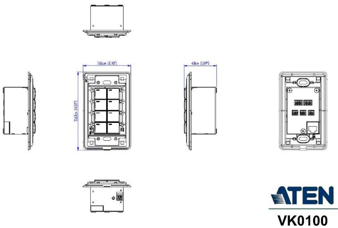
ATEN
VK0100
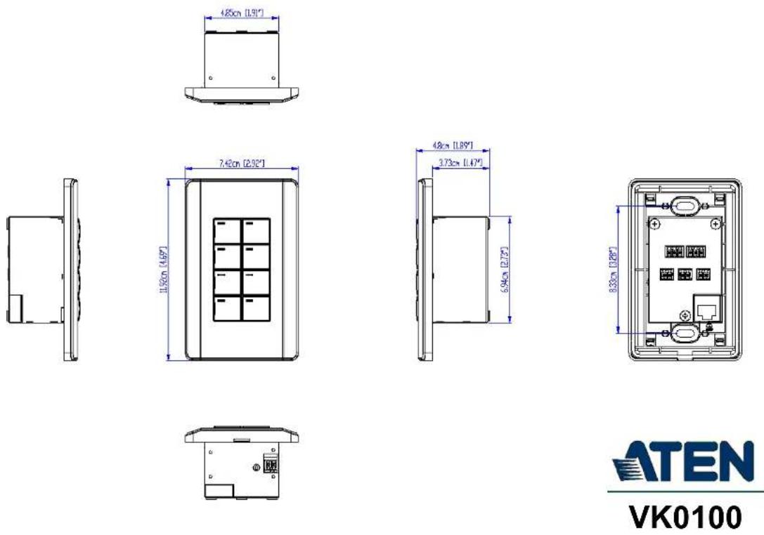
ATEN
VK0100
Panel Mount Cutout
![Width of faceplate = 7.4 cm [2.92"] Height of faceplate = 11.9 cm [4.69"] 5.4 cm [2.13"] 7.2 cm [2.83"] 8.4 cm [3.31"] Cutout Area 1.8 cm [0.71"]](/content/2026/05/1091984/images/f7e8d268b5be39167342f6b953240e2aa94c084589ccaea76d6dcd89b0aad042.jpg)
Note: ATEN recommends a 1-gang wall box with a depth of at least 5 cm (1.97 inches) to accommodate the connectors and cables.
ATEN
VK0100
CAD Drawings

ATEN
VK0200

ATEN
VK0200

ATEN
VK0200
Panel Mount Cutout
![Width of faceplate = 15.1 cm [5.95"] Height of faceplate = 8.6 cm [3.39"] 10.1 cm [3.98"] 5.4 cm [2.13"] Cutout Area](/content/2026/05/1091984/images/bc8f0bc52fc784733bb5f055039f0e111fedfb8e69087e1baa78e78ee6686f36.jpg)
Note: ATEN recommends a 2-gang wall box with a depth of at least 5 cm (1.97 inches) to accommodate the connectors and cables.
ATEN
VK0200
CAD Drawings

ATEN
VK108US
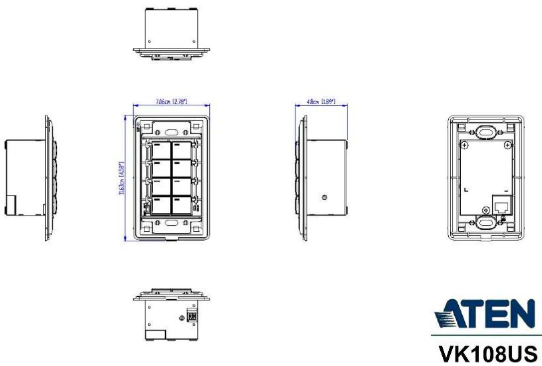
ATEN
VK108US
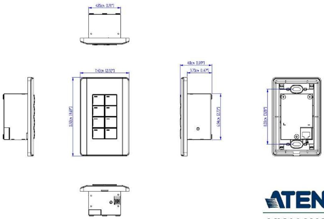
ATEN
VK108US
Panel Mount Cutout
![Width of faceplate = 7.4 cm [2.92"] Height of faceplate = 11.9 cm [4.69"] 5.4 cm [2.13"] 7.2 cm [2.83"] 8.4 cm [3.31"] Cutout Area 1.8 cm [0.71"]](/content/2026/05/1091984/images/a0cd302e5b39fcd34dabf8d24363dc9119790eb9b6c354275f2ce88bd8796059.jpg)
Note: ATEN recommends a 1-gang wall box with a depth of at least 5 cm (1.97 inches) to accommodate the connectors and cables.
ATEN
VK108US
CAD Drawings

ATEN
VK112EU

ATEN
VK112EU
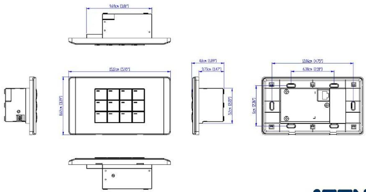
ATEN
VK112EU
Panel Mount Cutout
![Width of faceplate = 15.1 cm [5.95"] Height of faceplate = 8.6 cm [3.39"] 10.1 cm [3.98"] 5.4 cm [2.13"] Cutout Area](/content/2026/05/1091984/images/a744688c9f1c009302a9595e9488aa13344578cc6d479b689a0ac8997218b9b4.jpg)
Note: ATEN recommends a 2-gang wall box with a depth of at least 5 cm (1.97 inches) to accommodate the connectors and cables.
ATEN
VK112EU
Datapoint Types
ATEN Control System supports the following KNX Datapoint Types (DPT):
| DPT ID DPT Format DPT Name | ||
| 1.001 B | 1 | DPT_Switch |
| 1.002 B | 1 | DPT_Bool |
| 1.003 B | 1 | DPT_Enable |
| 1.004 B | 1 | DPT_Ramp |
| 1.005 B | 1 | DPT_Alarm |
| 1.006 B | 1 | DPT_BinaryValue |
| 1.007 B | 1 | DPT_Step |
| 1.008 B | 1 | DPTUpDown |
| 1.009 B | 1 | DPT_OpenClose |
| 1.010 B | 1 | DPT_Start |
| 1.011 B | 1 | DPT_State |
| 1.012 B | 1 | DPT_Invert |
| 1.013 B | 1 | DPT_DimSendStyle |
| 1.014 B | 1 | DPT_InputSource |
| 1.015 B | 1 | DPT_Reset |
| 1.016 B | 1 | DPT_Ack |
| 1.017 B | 1 | DPT_Trigger |
| 1.018 B | 1 | DPT_Occupancy |
| 1.019 B | 1 | DPT_Window_Door |
| 1.021 B | 1 | DPT_LogicalFunction |
| 1.022 B | 1 | DPT_Scene_AB |
| 1.023 B | 1 | DPT_ShutterBlinds_Mode |
| 1.100 B | 1 | DPT_Heat/Cool |
| 2.001 B | 2 | DPT_Switch_Control |
| 2.002 B | 2 | DPT_Bool_Control |
| 2.003 B | 2 | DPT_Enable_Control |
| 2.004 B | 2 | DPT_Ramp_Control |
| 2.005 B | 2 | DPT_Alarm_Control |
| 2.006 B | 2 | DPT_BinaryValue_Control |
| 2.007 B | 2 | DPT_Step_Control |
| 2.008 B | 2 | DPT_Direction1_Control |
| 2.009 B | 2 | DPT_Direction2_Control |
| 2.010 B | 2 | DPT_Start_Control |
| 2.011 B | 2 | DPT_State_Control |
| 2.012 B | 2 | DPT_Invert_Control |
| 3.007 B | 1U3 | DPT_Control_Dimming |
| 3.008 B | 1U3 | DPT_Control_Blinds |
| 4.001 A | 8 | DPT_ASCII |
| 4.002 A | 8 | DPT_Char_8859_1 |
| 5.001 U | 8 | DPT_Scaling |
| 5.003 U | 8 | DPT_Angle |
| 5.004 U | 8 | DPT_Percent_U8 |
| 5.005 U | 8 | DPT_DecimalFactor |
| 5.006 U | 8 | DPT_Tariff |
| 5.010 U | 8 | DPT_Value_1_Ucount |
| 6.001 V | 8 | DPT_Percent_V8 |
| 6.010 V | 8 | DPT_Value_1_Count |
| 6.020 B | 5N3 | DPT_Status_Mode3 |
| 7.013 U | 16 | DPT_Brightness |
| 8.011 V | 16 | DPT_Rotation_Angle |
| 9.001 F | 16 | DPT_Value_Temp |
| 18.001 B | 1R1U6 | DPT_SceneControl |
| 20.100 N | 8 | DPT_FuelType |
| 20.101 N | 8 | DPT_BurnerType |
| 20.102 N | 8 | DPT_HVACMode |
| 20.103 N | 8 | DPT_DHWMode |
| 20.104 N | 8 | DPT_LoadPriority |
| 20.105 N | 8 | DPT_HVACContrMode |
| 20.106 N | 8 | DPT_HVACEmergMode |
| 20.107 N | 8 | DPT_ChangeoverMode |
| 20.108 N | 8 | DPT_ValveMode |
| 20.109 N | 8 | DPT_DamperMode |
| 20.110 N | 8 | DPT_HeaterMode |
| 20.111 N | 8 | DPT_FanMode |
| 20.112 N | 8 | DPT_MasterSlaveMode |
| 20.113 N | 8 | DPT_StatusRoomSetp |
| 23.001 N | 2 | DPT_OnOff_Action |
| 23.002 N | 2 | DPT_Alarm_Reaction |
| 23.003 N | 2 | DPTUpDown_Action |
| 23.102 N | 2 | DPT_HVAC_PB_Action |
ATEN Control Box Reset Button
The reset button on ATEN Control Boxes can be used to reset system settings as described below.
| Reset Button Functions | ||
| Control Box ON/OFF | Operation Description | |
| ON Short press | Resets the Control Box's network | settings. |
| Press and hold until the front panel LEDs blink once, with the buzzer beeping once (about 8 seconds) | Resets all settings back to factory default (deleting all Viewers, Projects, and account/password) but retains the network and license settings. | |
| OFF While pressing | singing and holding, turn on the Control Box, and release when the buzzer beeps once, with the front panel LEDs blinking. | Enters Recovery Mode without resetting the Control Box's settings. |
| While pressing and holding, turn on the Control Box, and release when the buzzer beeps twice, with the front panel LEDs blinking. | Resets all settings back to factory default but retains the license settings, and enters Recovery Mode. | |
| While pressing and holding, turn on the Control Box, and release when the buzzer beeps 3 times, with the front panel LEDs blinking. | Resets all of the Control Box's settings, including Viewers, Projects, account/password, network, and licenses. | |
Windows OS Button Limitation
There is a limitation for overlapping buttons when adding buttons for a Viewer to be used on Windows mobile devices. When two or more buttons are layered on one another, such as (A) on top of (B), users are unable to press the top most button (A), and instead triggers the bottom button (B) every time trying to press (A). To resolve this issue, copy the top most button (A), and add the duplicate (C) under both (A) and (B) on the Viewer.

When the top button (A) is pressed, the lowest button (C) is executed.
ATEN Standard Warranty Policy
The warranty policy may vary by product category and region of purchase. For details, please visit ATEN's official website, select your purchase counties/regions and then go to the Support Center, or contact your local ATEN sales representative for further assistance.
© Copyright 2024 ATEN® International Co., Ltd.
Released: 2024-11-18
ATEN and the ATEN logo are registered trademarks of ATEN International Co., Ltd. All rights reserved. All other brand names and trademarks are the registered property of their respective owners.
- VK Series & Configurator
- ATEN Control System User Manual
- Compliance Statements
- FEDERAL COMMUNICATIONS COMMISSION INTERFERENCE STATEMENT
- FCC Caution
- Warning
- Achtung
- Industry Canada Statement
- CAN ICES-003 (A) / NMB-003 (A)
- RoHS
- User Information
- Online Registration
- Telephone Support
- User Notice
- Product Information
- Package Contents
- VK0100
- VK0200
- VK1100A
- VK1200
- VK2100A
- VK2200
- VK112EU
- VK108US
- VK224
- VK236
- VK248
- VK258
- VK320
- VK330
- Latest Package Edition
- Previous Package Edition
- Contents
- Introduction
- Hardware Setup and Panel Operation
- Web-based Configuration and Control
- ATEN Configurator (VK6000)
- ATEN Database Generator
- Remote PC Control
- ATEN Control System App
- Appendix
- About this Manual
- Chapter 1, Introduction
- Chapter 2, Hardware Setup
- Chapter 3, Browser Operation
- Chapter 4, ATEN Configurator (VK6000)
- Chapter 5, ATEN Database Generator
- Chapter 6, Remote PC Control
- Chapter 7, ATEN Control System App
- Note:
- Conventions
- What's New in Version 3.7
- Chapter 1
- Introduction
- Overview
- Benefits
- Intelligent Control
- Optimized Performance
- Simplified Setup
- Effortless Expandability
- User-Oriented Convenience
- On-the-Go Control
- Features
- Controllers
- ATEN Control Box Gen. 2
- ATEN Control Pad
- ATEN Configurator
- Control Interfaces
- ATEN Keypads
- ATEN Touch Panel
- ATEN Control System App
- Accessories
- Access Inspector (VK401)
- Requirements
- ◆ Hardware devices to be controlled by your ATEN controller
- ♦ Cables
- - A computer for configuring your ATEN Control System
- ♦ (Optional) Remote control through 10 or 32 mobile devices respectively for Control Pad or VK1200 / VK2200
- Chapter 2
- Hardware Setup and Panel Operation
- ATEN Control Box
- VK1100A / VK1200 / VK2100A / VK2200 Panel Components
- VK1100A Front View
- Placement
- Desktop
- Rack Mounting
- ■ VK2100A / VK2200
- ■ VK1100A / VK1200
- Single Rack Mount (2X-049G)
- Double Rack Mount (2X-021G)
- ■ VK1100
- Control Box Connections
- VK1100A Installation Diagram
- VK1200 Installation Diagram
- VK2100A Installation Diagram
- V DC Power Output
- Independent Power Supply
- Digital Output Power Supply
- Digital Output Dual Power Supply (VK2100A/ VK2200 only)
- Relay
- Using Self-supplied Power
- Connects to room control equipment
- Relay Power Supply
- Application: Control Using External Relays
- IR / Serial
- Digital I/O
- Digital Input (Dry Contact):
- Digital Input (VDC Mode):
- RS-232 (3-Pin)
- RS-232 / 422 / 485 (DB-9)
- RS-232 / 422 / 485 (5-Pin)
- Ethernet / Control LAN
- Panel Components
- LED Indications
- Installing the Control Pads
- Wiring Information
- RS-232 Serial Connection
- Relay Connections
- Digital Input Device
- Digital Input (VDC):
- Ethernet
- ATEN Expansion Box
- Control Interface Devices
- ATEN Keypad
- Hardware Overview VK108US
- Layout Examples
- Installing ATEN Keypad
- VK112MK
- ATEN 8" Touch Panel (VK320)
- Hardware Overview
- Mounting the VK320 Touch Panel
- Wall Mount
- PoE
- - Terminal block
- Tabletop Mount using the VK102 Tabletop Kit
- Configuring Network Settings
- Changing the Interface Language
- Updating Control System App
- Upgrading Firmware for ATEN Touch Panel
- Other Configurations & Actions
- ATEN 10" Touch Panel (VK330)
- Mounting the Touch Panel
- Desk Mount
- Installing the Touch Panel
- Operating the Touch Panel
- Configuring the Network Settings
- VK401 Access Inspector
- Components
- Installing an Access Inspector to a VK330 Touch Panel
- Chapter 3
- Web-based Configuration and
- Control
- Determining the IP Address of the Controller
- LCD Panel
- IP Installer
- Login
- Dashboard
- Settings
- General
- Setting Descriptions
- Licenses for Mobile Control
- Storage
- Access Viewers in Web URL for Remote Control
- Access
- Monitor
- Network
- Working as a DHCP Server
- Connections
- Schedule
- Security
- Chapter 4
- ATEN Configurator (VK6000)
- Installing ATEN Configurator
- Click Next. This screen appears.
- If you agree with the License Agreement, select I accept the terms of the license agreement, and click Next. Click Print to print the Software End User License Agreement. This screen appears.
- Getting Started Tasks
- Main Screen
- Menu Bar
- Creating Projects
- Control Description
- Configuring Managed Devices
- Left Sidebar
- Controller
- Room
- Expansion Box
- Device Configuration List
- Adding Devices to the Device Configuration List
- Adding Non-KNX-Compliant Devices to ATEN Configurator
- Via ATEN Device Library or My Library
- Via the Properties Column
- Adding KNX Devices
- Adding a KNX Device
- Importing an ETS Project
- Device Properties
- Controller Properties
- Expansion Box (Expander)
- Serial Device Properties
- Properties
- Connection Settings
- Advanced
- Keep Connection Alive
- I/O Device Properties
- IR/Relay Device Properties
- Ethernet Device Properties
- - Connection Settings
- ◆ Monitor Connection
- Migrating Devices to another Controller
- Library
- Device Library
- Configuring the Control Interface (Viewer)
- The Design Tab
- ① Viewer List
- ② Monitor / Control List
- Configuration Panel
- Library
- Simulator
- Adding Viewers
- Deciding How Many & What Viewer to Create
- Scenario 1
- Scenario 2
- Configuring a Viewer
- ◆ Touch Panel
- Click Done to save the configuration. An overview appears.
- Adding / Removing a Page
- Configuring a Subpage
- For example:
- Duplicating a Viewer
- Viewer Control Objects
- Understanding Control Objects
- Configuring Control Objects
- Element Tasks
- Control Object Properties
- Buttons
- ♦ Dialog
- Message
- Groups
- Labels
- Slider Bars
- Basic Slider Bar
- Advanced Slider Bar
- PowerPoint Control and Media Control Templates
- Images
- Layering Images
- Videos
- Setting Up a Video Preview Window
- Setting Up a Video Control Window
- Important:
- Click the added object and configure the action.
- Setting Up a Video Streaming Window
- Dial Kit
- Note: The image and color settings are only applicable to dial keys.
- Frame & Line
- Object Properties for ATEN Keypad / Control Pad
- Mode
- Button / Slider Bar / Dial Kit Actions
- Understanding Button/Slider Bar/Dial Kit Actions
- Configuring Button/Slider Bar Actions
- Functions
- Device Functions
- - Value Types
- Applications of Device Functions
- Example: Configuring actions of dial keys.
- Advanced Functions
- Applications of Advanced Functions
- Set Flag
- Condition
- Change Button State
- Change Label
- Change Group Button State
- Change Slider Bar Level
- Change Button Name
- Example:
- Graphic Library
- Button
- Background
- Image (Device Icon)
- Device Interface
- Flag
- Understanding Monitor
- Monitor Page Options
- Condition Types
- - Listen to port / Query port
- - Select string with a non-fixed length
- - Drop-Down Menu
- - Flag
- I/O Input
- Creating an If Monitor
- Creating a Switch Monitor
- Creating a Bypass Monitor
- Creating a While Loop Monitor
- Creating a Professional Monitor
- Configure the Action settings.
- b) Add actions.
- Duplicating a Created Monitor
- Macro
- To create a macro:
- Scheduled Events
- Creating a Scheduled Event
- Duplicating a Scheduled Event
- Variables
- Understanding Variables
- Creating a Variable for Devices that Return Feedback Messages
- Creating a Variable for Devices that Do Not Return Feedback Messages
- Creating a Button for Bypassing Feedback to a Variable
- Timers
- Configuring a Timer Event
- Duplicating a Created Timer
- Centralized Monitoring and Control via Unizon™
- Unizon™
- Monitor ATEN-controller-managed Devices via Unizon™
- Control ATEN-controller-managed Devices via Unizon™
- Enabling Monitoring and Control via Unizon™
- Creating a Monitor Item
- Creating a Control Item
- Removing a Monitor / Control Item
- The Upload Tab
- Click Upload to Controller.
- Viewing Controller Information
- Chapter 5
- ATEN Database Generator
- Accessing the Database Generator
- My Library
- Function Tabs
- Tab Description
- Controls on the My Library Window
- EDIT
- Search
- Editing / Adding a New Device
- Serial Device
- Text Command Tools
- IR Device
- Digital Output Device
- Relay Device
- Ethernet Device
- - Settings
- Testing Commands
- Configuring Queries
- ATEN Library
- Chapter 6
- Remote PC Control
- Specifications
- Setting Up Remote PC Control
- Installing ControlAssist on Target Computers
- Adding Target Computers to the Control System
- Configuring a Control Interface
- Example 1:
- Example 2:
- Chapter 7
- Installing the App
- Demo/Start Screen
- WinViewer1 / iPad / Android1
- Demo
- Control Pages
- Welcome (List of Viewers) Page
- Manage Viewer
- Manage LAN Device
- ONVIF
- TCP
- UDP
- Simulating Viewer Controls with Demo Mode
- Log Report
- Preferences
- Receiving Room Usage Notifications from ATEN Room Booking System
- Allowing Room Usage Notifications
- Remote RBS Control
- AppSwitcher
- Adding Apps to ATEN Touch Panel And AppSwitcher
- Using AppSwitcher
- Report History
- Information
- Download Viewer
- Downloading Viewers
- Safety Instructions
- Rack Mount
- Technical Support
- International
- Reset Button
- Power
- Environmental
- Physical Properties
- Mobile Control License
- Interfaces
- RS-232
- RS-422
- RS-485
- Panel Mount Cutout
- CAD Drawings
- Datapoint Types
- ATEN Control Box Reset Button
- Windows OS Button Limitation
- ATEN Standard Warranty Policy
Brand : ATEN
Model : VK224
Category : Electronic control system