
RGB2VGA - Video Converter Smart-AVI - Free user manual and instructions
Find the device manual for free RGB2VGA Smart-AVI in PDF.


| Product Type | Video Converter |
| Brand | Smart-AVI |
| Model | RGB2VGA |
| Input Interfaces | RGB, RGBS, CGA/EGA (via optional adapter), DVI |
| Output Interfaces | DVI-I (with VGA adapter included) |
| Maximum Output Resolution | 1280x1024@75Hz (VGA) / 1280x1024@60Hz (DVI) |
| Refresh Rates | 50Hz, 60Hz, 75Hz |
| Color Depth | 15-bit (5-bit per channel) |
| Bandwidth | 165 MHz |
| Power Supply | 6V DC, 2A (universal PSU 90-240VAC) |
| Power Consumption | Approx. 8W |
| Dimensions (W x D x H) | 6.7 x 5.2 x 1.7 inches (170 x 133 x 44 mm) |
| Weight | 1.0 kg (2.2 lb) |
| Operating Temperature | 41 to 113°F (5 to 45°C) |
| Storage Temperature | -13 to 140°F (-25 to 60°C) |
| Humidity | max. 80% non-condensing |
| Scaling Modes | 1:1 (no scaling), Full screen (non-proportional), Proportional, 1:2 (double size) |
| On-Screen Display (OSD) | Yes, with infrared remote control or Windows software |
| Diagnostic LEDs | Monitor Detect (green), Device Ready (red), Video Signal (green) |
| Package Contents | Converter unit, RGB(S)-to-DVI cable, DVI-I-to-VGA adapter, power supply, programming cable, infrared remote, user manual |
| Warranty | Refer to manufacturer; no user-serviceable parts |
Frequently Asked Questions - RGB2VGA Smart-AVI
User questions about RGB2VGA Smart-AVI
0 question about this device. Answer the ones you know or ask your own.
Ask a new question about this device
Download the instructions for your Video Converter in PDF format for free! Find your manual RGB2VGA - Smart-AVI and take your electronic device back in hand. On this page are published all the documents necessary for the use of your device. RGB2VGA by Smart-AVI.
USER MANUAL RGB2VGA Smart-AVI
Welcome to the RGB to DVI(/VGA) Converter Family!
Thank you for purchasing an RGB to DVI(/VGA) Converter! We appreciate your business, and we think you'll appreciate the many ways that your enhanced RGB Graphic system will save you money, time, and effort.
That's because our RGB to DVI(/VGA) Converter is all about breaking away from the traditional model of attaching a new display to an old graphic source. You can encounter many potential problems in connecting a flat screen to an RGB graphic source – unless you use our RGB to DVI(/VGA) Converter products! Attach a flat screen to any graphic source and match the output to your requirements. The RGB to DVI(/VGA) Converter – the one-stop answer for all your RGB adapting needs! And with a special adaptor cable (not supplied as standard), you can also attach a screen to a CGA or EGA source.
This manual will tell you all about your new RGB to DVI(/VGA) Converter, including how to install, operate, and troubleshoot it. For an introduction to the Converter, see Chapter 2. The Converter product codes covered in this manual are:
K238-3F: RGB to DVI (or VGA) Converter
Copyrights and Trademarks
©2005. All rights reserved. This information may not be reproduced in any manner without the prior written consent of the manufacturer.
Information in this document is subject to change without notice and the manufacturer shall not be liable for any direct, indirect, special, incidental or consequential damages in connection with the use of this material.
All trademark and trade names mentioned in this document are acknowledged to be the property of their respective owners.
Disclaimer
While every precaution has been taken in the preparation of this manual, the manufacturer assumes no responsibility for errors or omissions. Neither does the manufacturer assume any liability for damages resulting from the use of the information contained herein. The manufacturer reserves the right to change the specifications, functions, or circuitry of the product without notice.
The manufacturer cannot accept liability for damage due to misuse of the product or due to any other circumstances outside the manufacturer's control (whether environmental or installation related). The manufacturer shall not be responsible for any loss, damage, or injury arising directly, indirectly, or consequently from the use of this product.
Cautions and Notes
The following symbols are used in this guide:

CAUTION. This indicates an important operating instruction that should be followed to avoid any potential damage to hardware or property, loss of data, or personal injury.

NOTE. This indicates important information to help you make the best use of this product.
EUROPEAN UNION DECLARATION OF CONFORMITY
This is to certify that, when installed and used according to the instructions in this manual, together with the specified cables and the maximum cable length <3m, the Units are shielded against the generation of radio interferences in accordance with the application of Council Directive 89/336/EEC as well as these standards:
EN 55022: 1999 Class B
EN 55024: 1999
IEC 61000-4-2: 2001
IEC 61000-4-3: 2001
IEC 61000-4-4: 2001
EN 61000-3-2 2001
EN 61000-3-3 2002
The device was tested in a typical configuration with PC.
CE
Safety Precautions and Installation Guidelines
To ensure reliable and safe long-term operation, please note the following installation guidelines:
- Only use in dry, indoor environments.
- The Converter and any power supplies can get warm. Do not locate them in an enclosed space without any airflow.
- Do not place a power supply directly on top of a unit.
- Do not obstruct a unit's ventilation holes.

To safeguard against personal injury and avoid possible damage to equipment or property, please observe the following:
- Only use power supplies originally supplied with the product or manufacturer-approved replacements. Do not attempt to dismantle or repair any power supply. Do not use a power supply if it appears to be defective or has a damaged case.
- Connect all power supplies to grounded outlets. In each case, ensure that the ground connection is maintained from the outlet socket through to the power supply's AC power input.
- Do not attempt to modify or repair this product
Contents
1. Quick Setup 8
1.1 Video Input/Output 9
1.2 Command Summary 10
2. Overview 11
2.1 Introduction 11
2.2 Glossary 11
2.3 Features 13
2.4 Product Range 14
2.5 Compatibility 15
2.6 How to Use This Guide 15
3. Installation 17
3.1 Package Contents 17
3.2 Connection Cable Requirements 18
3.3 System Setup 19
3.4 Diagnostic LEDs 21
4. Device Control 22
4.1 Opening the OSD 23
4.2 Using the OSD 25
5. Monitor Setup 34
6. RGB to DVI(/VGA) Converter Setup 35
6.1 Overview 35
6.2 Setup Instructions for RGB Input 36
6.3 Setup of a new Video Mode 38
7. Troubleshooting 40
7.1 Video 40
Appendix A: Example Applications 42
Appendix B: Rack Mount Options 43
Appendix C: System Upgrade 45
Appendix D: Supported Video Modes 45
Appendix E: Calling Technical Support 48
Appendix F: Specifications 49
Appendix G: Connectors and Cables 50
1. Quick Setup
This section briefly describes how to install your RGB to DVI(/VGA) Converter and optimize the video signals. Unless you are an experienced user, we recommend that you follow the full procedures described in the rest of this manual. Refer to the command summary on page 10 when following this procedure.
![graph TD A["Install system\n1. Connect the RGB to DVI(/VGA) Converter to the RGB (video) source.\n2. Connect a display to the RGB to DVI(/VGA) Converter.\n3. Power up the system."] --> B{Do you have a DVI monitor?} B -->|No| C["Do you have a flat screen (TFT)?"] B -->|Yes| D{Is the RGB video mode in…](/content/2026/05/1091549/images/296502ac1974937386d74e5559485bf8331de7b4213d15e02fae10649db91079.jpg)
1.1 Video Input/Output
If possible, always use a DVI output to a monitor from the RGB to DVI(/VGA) Converter, especially with flat screens. This provides the optimum video signal. If you use a VGA output from the RGB to DVI(/VGA) Converter, it must convert the digitized data to analogue values. Similarly, if your TFT screen uses a VGA input, it must digitize the signal from the RGB to DVI(/VGA) Converter. In these cases, the built-in video processors (in the TFT) must determine the resolution and pixel phase for an optimized digitization. Your RGB to DVI(/VGA) Converter allows you to optimize the video signal manually or automatically using its on-screen utility (see Chapter 4). If you are using a VGA input to a TFT monitor, please follow the manufacturer's instructions.
You may have several possible options for video source output/monitor input. If this is the case, for the optimum video quality, please select the highest ranked available combination from the following table:
| Video Quality | RGB to DVI(/VGA) Converter input | RGB to DVI(/VGA) Converter output |
| 1 | RGB progressive scan | DVI |
| RGBS progressive scan | ||
| 2 | RGB video (e.g. from SCART) interlaced | DVI |
| 3 | RGB progressive scan | VGA |
| RGBS progressive scan | ||
| 4 | RGB video (e.g. from SCART) interlaced | VGA |
1.2 Command Summary
The following table summarizes the remote control buttons and 'hot' key command sequences used in system configuration and video tuning on the RGB to DVI(/VGA) Converter.
| Infrared Remote Control (IR-RC) | Command | Utility * |
| Exit OSD | <X> | |
| Enter OSD | <O> + <S>+ <D>+ <Enter> | |
| Accept and store modified parameter | ||
| Select Submenu | <S> | |
| Select parameter modification | ||
| Select next position | <R> | |
| Increase parameter | ||
| Select previous position | ||
| Decrease parameter | ||
| Direct Brightness Control | ||
| Direct Contrast Control | ||
| Reset to factory defaults (press twice!) | ||
| Back to the Menu selection |
* Commands are not case-sensitive.
2. Overview
2.1 Introduction
VGA is the most familiar of the various graphics data standards or protocols for connecting a display (monitor or flat screen) to a graphic source. For many years, computers have generally connected to a display through a VGA interface. However, with the increased popularity of TFT flat screens, a new standard has been developed: DVI. In DVI, graphic data is transmitted digitally; VGA is an analogue standard.
Over the years, other analogue standards have also found popularity: CGA, EGA and also RGB. An RGB Video transmission consists of R (red), G (green) and B (blue) signals at a level of 0.7Vpp. The Green signal also carries the (composite) synchronisation signals.
A screen designed for VGA cannot normally display RGB signals for two reasons:
- A VGA screen requires H/V-Synchronization as TTL signals
- Many RGB sources generate HSYNC frequencies below of 30kHz – to slow for modern VGA displays.
With TFT screens, there is an additional problem: the incoming video signal has to be digitised. Horizontal and vertical resolutions are normally selected from an internal table with several, common, video modes. Unusual resolutions, often generated by older RGB graphic sources cannot be detected.
To display RGB data on a modern VGA or DVI display, the RGB to DVI(/VGA) Converter digitises the incoming signals, stores them in an internal video memory and displays them from there in a common resolution. The picture can be displayed in original size or format filling. The RGB to DVI(/VGA) Converter is equipped with various automatic and manual video correction tools in an on screen utility (see page 22).
2.2 Glossary
The following terms are used in this guide:
| RGB | Video signal consisting of R (red) G (green) and B (blue) signals. The signals have a level of 0.7Vpp. The Green signal also carries the (composite) synchronisation signals. |
| RGBS | Video signal consisting of R (red) G (green) and B (blue) signals and the additional (composite) SYNC signal. All signals have 0.7Vpp. |
| CGA/EGA | Legacy graphic standard - all signals are TTL level. |
| VGA (also called RGBHV) | Video signal consisting of R (red) G (green) and B (blue) signals and the additional horizontal/vertical synchronisation signals. The color signals have a level of 0.7Vpp; the synchronisation TTL (5Volts). |
| DVI | Digital Video standard established by the Digital Display Working Group (www.ddwg.org). R, G, B, CLOCK signals in an up to 1.4 Gbit/sec data stream. The signals have a TMDS level. |
| PSU | The desktop power supply for the RGB to DVI(/VGA) Converter. |
THE RGB TO DVI(/VGA) CONVERTER
![graph TD A["PLC – programmable logic controller"] --> C["Video-Equipment (DVD, VCR, Set-top)"] B["Legacy CPU’s"] --> C C --> D["RGB to DVI(/VGA) Converter"] D --> E["Computer monitor"]](/content/2026/05/1091549/images/6e08765a009fc5eb865d6196cb2f84a538ef9eabad79b95dc0b0447931a6400d.jpg)
Figure 1 RGB to DVI(/VGA) Converter system
2.3 Features
RGB to DVI(/VGA) Converter offers the following features:
• Support for RGB and RGBS in progressive scan or interlaced mode.
• Support for EGS/CGA using the optional Adaptor + Cable (436-EG).
- Selectable output for attached display: 640x480, 800x600, 1024x768, 1280x1024.
- Refresh rate selectable for best match to CRT or TFT – 50Hz, 60Hz or 75Hz.
• Picture scaling available:
- No scaling – original picture is centered into a black box.
- Format filling – the picture is stretched to fit the screen.
- Proportional stretching – the picture is stretched linearly in both dimensions with the same factor, until one dimension fits the screen size.
- Fixed scaling – scaled to 1:2 and displayed with (eventually) black borders.
- All control and video tuning carried out using an on screen display (OSD) with settings stored in EEPROM memory.
• A large table of known RGB resolutions (more than 80) preinstalled.
• Private video mode available through OSD.
- RGB to DVI(/VGA) Converter firmware and settings flash-upgradeable.
• Status indicator LEDs on each device.
- Small footprint chassis.
- Rack mount options available.
• Video cables and adaptors included.
Optional accessories:
- EGA/CGA to DVI Adaptor: Type 436-EG
- Rack mount Kit 19"/1U: Type 437-1G
2.4 Product Range
This table lists the product codes for the converter and its various upgrade kits:
| RGB to DVI(/VGA) Converter | |||
| K238-3F RGB to DVI (or VGA) Converter | |||
| Upgrade Kits | |||
| 436-EG EGA/CGA to DVI Adaptor + Cable | |||
| 437-1G 19"/1U Rackmount Kit for up to 3 | |||
| 437 -G2 Double-width housing for 2 devices | |||
| 433-1U 19"/1U housing for up to 3 devices with internal, common power supply | |||
| 433-2U 19"/2U housing for up to 6 devices with internal, common power supply | |||
| 285-2K Mounting Brackets (screw-fixed) | |||
| 286-2K Mounting Brackets (snap-on) | |||
| 260-6H Universal switch mode p.s.u. 90...230VAC/6VDC-2A |
2.5 Compatibility
Interface Compatibility
- RGB: Video signal consisting of R (red) G (green) and B (blue) signals. The signals have a level of 0.7Vpp. The Green-Signal also carries the (composite) synchronisation signals.
- RGBS: Video signal consisting of R (red) G (green) and B (blue) signals and the additional (composite) SYNC signal. All signals have 0.7Vpp.
- VGA (also called RGBHV): Video signal consisting of R (red) G (green) and B (blue) signals and additional horizontal/vertical synchronisation signals. The color signals have a level of 0.7Vpp; the synchronisation TTL (5Volts).
- Digital Video (DVI): DVI single link for resolution up to 1280x1024 at 60/75Hz. Digital Video standard established by the Digital Display Working Group (www.ddwg.org) R, G, B, CLOCK in an up to 1.4 Gbit/sec data stream. The signals have a TMDS level.
- CGA (Colour Graphic Adaptor): Legacy graphic standard, established by IBM, supporting text with 40 or 80 characters in 25 lines with 16 colours or graphics in 640x200 with 2 colours or 320x200 with 4 colours.
- EGA: Legacy graphic standard (Enhanced Graphic Adaptor), established by IBM, supporting text with 80 characters in up to 43 lines graphics in 640x350 in 16 colours from a palette of 64.
Supported SYNC forms
- RGsB: RGB with SYNC on Green. The colour signals have a level of 0.7Vpp. The Green-Signal also carries the (composite) synchronisation signals (app. -0.3V)
- RGBs: RGB with composite SYNC signal. All signals have 0.7Vpp.
- RGBS: RGB with composite SYNC signal. The colour signals have 0.7Vpp, the SYNC Signal is TTL-Level (5V)
- RGBHV: RGB with separate SYNC signals. The colour signals have 0.7Vpp, the SYNC Signals have TTL-Level (5V)
- MDA: black and white with separate SYNC signals (e.g. HERCULES). All Signals have TTL-Level (5V) (with EGA/CGA to DVI Adaptor only)
- CGA: colour with separate SYNC signals. All Signals have TTL-Level (5V) (with EGA/CGA to DVI Adaptor only)
- EGA: colour (2 pins per colour) with separate SYNC signals. All Signals have TTL-Level (5V) (with EGA/CGA to DVI Adaptor only)
2.6 How to Use This Guide
This guide describes the installation and configuration of the RGB to DVI(/VGA) Converter. Although the connection and operation of the system is relatively straightforward, you should consider the following before getting started:
Connection & Compatibility
If you have purchased an RGB to DVI(/VGA) Converter Kit, this will contain PSU and all the cables/adapters required to connect the RGB to DVI(/VGA) Converter to your graphic source. See also Package Contents (page 17)
For information about connection and installation, see Installation, page 17.
Adjusting the RGB to DVI(/VGA) Converter to RGB Video
Although there are several preconfigured resolutions stored in the internal resolution table of the RGB to DVI(/VGA) Converter, under some circumstances it is required to manually adapt the RGB to DVI(/VGA) Converter to your specific resolution: see RGB to DVI(/VGA) Converter Setup (page 35).
Adjusting the monitor to the RGB to DVI(/VGA) Converter
If you use a flat screen with VGA input, you will need to adjust the monitor to the picture width and the pixel phase. You can do this using the Auto Adjust or Manual Adjust procedures (see page 35).
- For experienced users there is a Quick Setup section at the start of this guide (see page 8).
- For the full procedure, see Monitor Setup (page 34) and/or RGB to DVI(/VGA) Converter Setup (page 35).
3. Installation
For first-time users, we recommend that you carry out a test placement, confined to a single room, before commencing full installation. This will allow you to identify and solve any cabling problems, and experiment with the RGB to DVI(/VGA) Converter more conveniently.
3.1 Package Contents
You should receive the following items in your RGB to DVI(/VGA) Converter package:
• RGB to DVI(/VGA) Converter unit.
- RGB(S) to DVI-I cable
- 6V DC 12W universal power supply for RGB to DVI(/VGA) Converter.
- DVI-I to VGA adaptor (DVI-I dual link male to HD15 female) connector.
• Programming cable (DB9 female to RJ11 4p4c).
- User manual (Quick Setup).
• German-type power cord.
• Infrared Remote Control (IR-RC)
The CGA/EGA to DVI Adaptor is supplied with:
• EGA to DVI-I adaptor
• DB9 female to DB9 male cable 1,8m
If anything is missing, please contact Technical Support (see Appendix E: Calling Technical Support).
3.2 Connection Cable Requirements
To connect the RGB to DVI(/VGA) Converter to your graphic source you will need:
- RGB(S): 3 (4 with RGBS) coaxial cables type RG59B/U or similar, terminated with BNC connectors at the converters end. Please ensure that the connection is tension-free.
• CGA: CGA/EGA to DVI Adaptor (with 436-CG upgrade kit only)
• EGA: CGA/EGA to DVI Adaptor (with 436-EG upgrade kit only) - Power Supply
Connect the supplied 6V/DC power supply to the Plug terminal on the rear of the RGB to DVI(/VGA) Converter.
3.3 System Setup
To install your RGB to DVI(/VGA) Converter:
-
Switch off all devices.
-
Connect your TFT directly to the device; connect a VGA screen by using the equipped DVI-I to VGA adapter.

Connect the VGA monitor cable to the adapter; then plug in the adapter into the device. Otherwise, the VGA mode is not detected, DVI output is generated and there will be no picture on the screen (see also Diagnostic LEDs on page 21).

Under some circumstances, if your TFT supports both DVI and VGA through a DVI-I cable, it might be necessary to use an additional DVI-I to DVI-D adaptor to get a DVI output. Please contact technical support for this accessory.
-
Connect the graphic source to the input connectors as shown in Figure 1, using the equipped 4xBNC-to-DVI adaptor. Please note, for connecting a CGA or EGA source, connect the optional CGA-to-DVI adaptor or EGA-to-DVI adaptor instead of the 4xBNC-to-DVI adaptor.
-
Connect the 6V power supply to power the unit.

Only use the power supply originally supplied with this equipment or a manufacturer-approved replacement.
- Power up the system.

Figure 2 RGB to DVI(/VGA) Converter
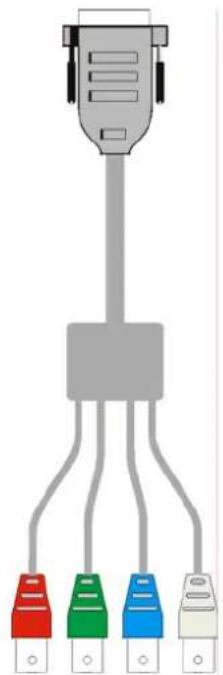
Figure 4 RGB-to-DVI Cable
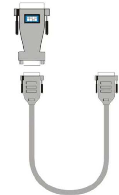
EGA/CGA
to
DVI
Converte
t y
(in list of parts) (NOT in list of parts - Option)
p
3.4 Diagnostic LEDs
Each RGB to DVI(/VGA) Converter is fitted with three indicator LEDs: Monitor Detect, Device Ready and Video Signal. The Monitor Detect LED is to the left of the video output connector. The Device Ready and Video Signal LEDs are next to the Power socket.
The location of the LEDs is shown below:
Monitor Detect

Video Signal Device Ready
(Green) (Red)
Figure 3 Diagnostic LEDs on RGB to DVI(/VGA) Converter
| LED | Appearance | Diagnostics |
| Monitor Detect | On | Attached DVI monitor (TFT) detected |
| Flashing | Attached VGA monitor (CRT) detected | |
| Off | No monitor detected | |
| Device Ready(Red LED) | Off | Device not ready |
| On | Device ready | |
| Video Signal(Green LED) | Off | No video signal or valid mode detected |
| On | Attached and valid mode detected |
4. Device Control
If you are using the CGA/EGA input (with adaptors only) or use an RGB format stored in the internal table, no adjustment should be required. In other cases, you may need to optimize the output using the RGB to DVI(/VGA) Converter's on-screen display (OSD).

Figure 4 OSD Utility
You can adjust the following properties using the IR-Remote Control:
- Brightness/contrast
You can adjust the following properties using the OSD:
• Auto Configuration ON/OFF
• Color, Color Temperature adjustments
- Brightness/contrast
- Input Image Sizing
• Output Image Scaling and Sizing
- Video Mode selection for similar Video Modes (see Appendix D: Supported Video Modes on page 45).
- OSD operation, factory reset.
4.1 Opening the OSD
You can access the OSD in three ways:
• Using the equipped Infrared Remote Control (IR-RC).
• Using our WINDOWS™ program with a serial connection to the programming port.
There is a summary of OSD commands on page 10.
Using the IR-RC
For direct brightness adjust For direct contrast adjust

more brightness
less brightness
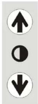
more contrast
less contrast
Reset to factory defaults
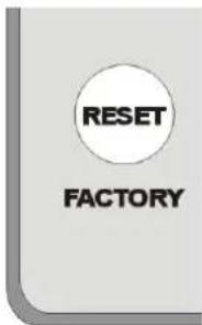
Reset to factory
defaults (from flash)
= resetting user
presets
(press twice !!)
To navigate within the OSD:

THE RGB TO DVI(/VGA) CONVERTER
Using our WINDOWS™ program
On all devices, you can use our small WINDOWS ™ program, running on a WINDOWS ™ computer for OSD access:
- Download the program from our server.
- Connect the programming cable to the programming port.
- Connect the programming cable to the serial port of your computer, where the program is running.
-
Start the program and follow the on-screen instructions.
-
Type in the following key sequence:
lt; O gt; + lt; S gt; + lt; D gt; followed by lt; ENTER gt
When the OSD starts, it displays information about the attached device and firmware version, for example:
To navigate within the OSD:
• Use the
- Press the <S> key to select the highlighted submenu or function.
- Select the Exit button to go back to the previous menu level.
- Press the <X> key to exit the OSD mode.
4.2 Using the OSD
The OSD is an icon-based utility. The top line of symbols shows the main menu categories:

Input Select
Specify whether the input is RGB (RGBS) or digital (for future expansion)

Scale Mode
Select the screen resolution of the attached display and select one of four scaling modes.
Brightness - Contrast
Adjust brightness or contrast or reset to default values.

Color
Adjust color calibration, temperature, flesh/skin tone, hue and saturation.

Image
Adjust pixel clock and phase. Define picture size and position.

Tools
Set OSD position and size, factory reset.
- Use the left and right arrow keys (
and keys in Windows program) to highlight the icon you want. The OSD displays additional icons relating to commands in the selected menu category. - Press the Enter key (
key in Windows program). The OSD highlights the first command icon. - Use the Left and Right arrow keys (
and keys in Windows program) to highlight the command or submenu you want. In the case of the latter, your selection will cause the OSD to display additional command icons (Color Temperature commands, for example). - Press the Enter key (
key in Windows program) to accept a highlighted command. If this requires the increase or decrease of a value (Contrast, for example), the OSD displays a value bar:

- Use the Left and Right arrow keys (
and keys in Windows program) to change the value as required.
THE RGB TO DVI(/VGA) CONVERTER
- In many cases, after you have chosen a new setting, the OSD displays the following confirmation message (or similar):

-
Highlight the key button and press the Enter key (
key in Windows program) to confirm your choice. Alternatively, highlight the No button and press the Enter key (key in Windows program) to discard the new setting and restore the previous value. -
Select the Exit icon to close a submenu.
-
Press the Esc key (
key in Windows program) to close the OSD, saving all settings, and restore normal mouse and keyboard functions.
The following table summarizes the keyboard actions and icons used to navigate the OSD utility, and to select and adjust the RGB to DVI(/VGA) Converter's parameters:
| Key/Icon | |||
| IR-RC | Terminal Windows program | or | Action |
 | Close the OSD, restore normal keyboard and mouse functions. | ||
 | Return to previous Menu selection. | ||
 | Open the highlighted menu or submenuAccept the highlighted command | ||
 | Select the previous menu or command iconDecrease the highlighted parameter | ||
 | Select the next menu or command iconIncrease the selected parameter | ||
Input Select (for future expansion)

disabled funtion for this firmware level

Select RGB (RGBS) source
Select digital input `(for future expansion)
Return to main menu
Figure 5 Input Select menu
Physical Resolution of attached screen

Use the Scale Mode menu to specify the physical resolution of the attached screen; this ensures the best matching pictures on a TFT screen. Use output scaling (see below) to stretch the picture to the maximum available screen space.

No change to the resolution/refresh: The output resolution/refresh rate is the same like the input resolution/refresh rate
Choice of four fixed screen resolutions at refresh rate of 60Hz (for LCD/flat screens) 640x480, 800x600, 1024x768, 1280x1024
Calling Output Scaling Sub-Menu
Select or Deselect line doubling for de-interlacing (video sources with interlaced signals only)
Return to main menu
Figure 6 Scale Mode menu
Choice of four fixed screen resolutions at refresh rate of 75Hz (for CRT/tube screens) 640x480, 800x600, 1024x768, 1280x1024
Select 50Hz Output-Mode for Video-Applications (resolution keeps unchanged – select before from Choice of four)
Output Scaling

Use the Output Scaling submenu to specify the best match between screen size and user requirements. Four modes are available:
1:1 – the picture is displayed with its original size and aspect ratio within a black frame. All pixels remain 1 wide and 1 high. Pictures with less than 300 lines are displayed in double height. Interlaced pictures are displayed in double height (deinterlaced)
OFF (Full screen) - The picture is stretched to fill all available screen space (non-proportional).
PROP (Proportional) – The picture is stretched (up scaling only!) to fill one screen dimension completely. The other dimension is made up with black borders (e.g. to keep a 16:9 ratio on scaling - proportional) Horizontal and vertical size of the screen must be both at least the size of the appropriate picture dimension.
1:2 – the picture is displayed at double the original size within a black frame. All pixels become 2 wide and 2 high. Horizontal and vertical size of the screen must be both at least the double size of the appropriate picture dimension.

Full Screen: the picture is stretched to fill all available screen space
No scaling: picture displayed in original size within black borders
Double size: picture displayed in original size within black border
Return to previous menu
Proportional: picture is stretched until one screen dimension is filled completely. The other dimension is made up with black borders (e.g. to keep 16:9 ratio on scaling)
Figure 7 Output Scaling sub-menu
Brightness/Contrast

Use this menu to adjust the brightness and contrast of the video image, or to adjust the black level of a display.

Figure 8 Brightness-Contrast menu
Select Colors and Color Temperatures
Use the Colors menu to adjust the color balance of the video image. The menu provides a number of options including automatic calibration, manual adjustment in RGB or CMY color space, hue and saturation adjustment and the setup of flesh/skin tone.

Hue Saturation Back to main menu
Automatic color calibration
Standard RGB color selection
View Color temperature submenu (see Color Temperature, page 36)
Flesh tone/Skin tone
Set up colors in CMY space – automatically adjusts settings in RGB space
Figure 9 Color menu
Color Temperature

Use the Color Temperature submenu to set up the color profile in RGB color space or by using one of five predefined color temperatures. To view this menu, select the Colors icon from the main menu and then select the Color Temperature icon.
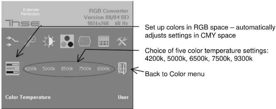
Figure 10 Color Temperature sub-menu
Image
Use the Image menu to adjust the vertical and horizontal screen position, picture size and to set the pixel clock and phase. Doing some tunings on SYNC problems.
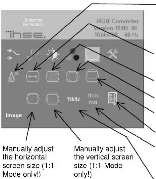
Figure 11 Image menu
Automatic detection of the number of pixels per line and the best phase (best point for A/D conversion within each pixel) see also RGB to DVI(/VGA) Converter Setup, page 35.
Manually adjust the number of pixels per line (Pixel clock)
Manually adjust the best phase (best point for A/D conversion within each pixel)
Manually adjust the horizontal picture position
Manually adjust the vertical picture position
Back to main menu
Select or deselect the threshold Checking on SYNC problems (see, page 40)
Select or deselect the 15kHz Glitch Filter on SYNC problems (see, page 40)
Tools

Use the Tools menu to set the position and size of the OSD window, adjust the sharpness for a fixed resolution setting, reset the RGB to DVI(/VGA) Converter system to its factory default settings or provide a test pattern.

Adjust sharpness (fixed resolution modes only). When resolution is changed by an imposed fixed resolution, sharpness can be affected. Use this option to switch between three settings for optimum sharpness
Display a 'burst' pattern for monitor setup (see Monitor Setup, page 34)
Figure 12 Tools menu
OSD
Use the OSD submenu to define the position and size of the OSD window. To view this menu, select the Tools icon from the main menu and then select the OSD icon.
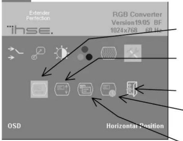
Figure 13 OSD sub-menu
Manually adjust the horizontal position of the OSD window
Manually adjust the vertical position of the OSD window
Back to Tools menu
Choose OSD Timeout ON/OFF (ON – OSD will disappear after some seconds. OFF – OSD will keep alive until user closes)
Toggle the size of the OSD window between single and double size
Factory Reset

Use the Factory Reset submenu to reset the unit to factory defaults, save user presets or restore user presets
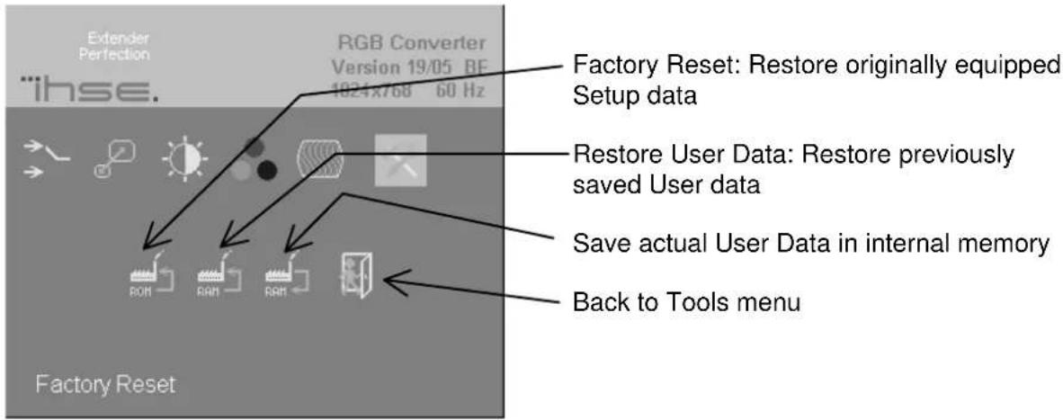
Figure 14 Factory Reset sub-menu
Auto Configuration

Use the Auto Configuration submenu to define whether the Converter carries out automatic detection of the number of pixels per line and the best phase after a mode change (a change of screen resolution and/or refresh rate at the graphic source).
Using automatic detection (while displaying an appropriate test pattern) ensures an optimized image but the procedure introduces a delay in the picture appearing on the attached console screen. If you want the picture to appear as fast as possible, you may want to disable this feature. Auto Configuration is disabled in the default factory settings.
To view the Auto Configuration menu, select the Tools icon from the main menu and then select the Auto Configuration icon.

Disable Automatic detection of pixels per line and phase after a mode change
Enable Automatic detection of pixels per line and phase after a mode change
Back to Tools menu
Figure 15 Auto-Configuration sub-menu
Video Mode

Use the Video Mode menu to select one of twelve Video Modes for a specific resolution. Please see (page 45) for more information about Video Modes and supported screen resolutions.

Choice of twelve different video modes. Please see also page 48
Figure 16 Video Mode menu
5. Monitor Setup
This procedure is designed to correct for discrepancies in the video signal due to analogue/digital video conversion by the Monitor. You do not need to follow this procedure if you have:
• A CRT monitor connected to the RGB to DVI(/VGA) Converter through the VGA input
• A TFT monitor connected to the RGB to DVI(/VGA) Converter through the DVI input
In these cases, there is no need to adjust the monitor because the video format is not converted.
Please make sure that you carry out this procedure before setting up the RGB to DVI(/VGA) Converter (page 35). If you are using a TFT monitor at the RGB to DVI(/VGA) Converter with a VGA cable, the TFT monitor digitizes the video data stream and this may affect video quality. By setting up the TFT monitor first, you ensure that you are correcting discrepancies due solely to the RGB to DVI(/VGA) Converter system in the RGB to DVI(/VGA) Converter Setup procedure.
- Connect the RGB to DVI(/VGA) Converter system and display the regular desktop in the desired screen resolution. Monitor Setup may vary depending on screen resolution and/or refresh rate.
- Display the OSD utility (see page 23).
- Select the Tools menu option (see page 31).
- Select the ‘burst’ pattern option. Your TFT should show fine, 1 pixel wide, black and white vertical stripes over the entire screen. The OSD will stay visible in the middle of the screen.
- Depending on the type of TFT, press the 'AUTO' Button on the monitor control panel or select Auto Adjust in the TFT Setup Menu. Refer to the manual supplied with your monitor for more information.
- If the vertical stripes are sharp and without jitter or smearing, the adjustment has been successful. Go to step 8.
- If the picture quality is not acceptable after the automatic adjustment, you will have to manually adjust the pixel clock and pixel phase (in this order). Please follow the instructions in your monitor's user manual.
- Press any key to exit the test pattern display.
- Exit the OSD.
6. RGB to DVI(/VGA) Converter Setup
6.1 Overview
You need to optimize the video signal across your RGB to DVI(/VGA) Converter system if it undergoes one or more conversions between analog and digital formats. The exact procedure depends on your RGB to DVI(/VGA) Converter setup:
| Graphics card | Monitor type | Monitor Input used | Video Optimization Procedure(s) | ||
| RGB/ CGA/ EGA | TFT | VGA | TFT adjustment (see Monitor Setup, page 34) Optimization using OSD (see Setup Instructions for RGB Input, page 36) | ||
| RGB/ CGA/ EGA | CRT | VGA | Optimization using OSD (see Setup Instructions for RGB Input, page 36) | ||
| RGB/ CGA/ EGA | TFT | DVI | Optimization using OSD (see Setup Instructions for RGB Input, page 36) | ||
| VIDEO | TFT | VGA | TFT adjustment only (see Monitor Setup, page 34) | ||
| VIDEO | CRT | VGA | No | setup | required |
| VIDEO | TFT | DVI | No | setup | required |
6.2 Setup Instructions for RGB Input
This procedure is designed to correct for discrepancies in the video signal due to analogue/digital video conversion by the RGB to DVI(/VGA) Converter. You do not need to follow this procedure if you have a digital signal, connected to the RGB to DVI(/VGA) Converter. In this case, the video signal is already converted into a digital format and digitally processed through the RGB to DVI(/VGA) Converter.
If you are using a TFT monitor at RGB to DVI(/VGA) Converter with a VGA cable, you should carry out the Monitor Setup procedure first (see page 34). In this configuration, the TFT digitize the video data stream and affect video quality. By setting up the TFT monitor, you ensure that you are correcting discrepancies due solely to the RGB to DVI(/VGA) Converter in this procedure. Alternatively, you could replace the TFT monitor with a CRT monitor while you carry out this procedure or use a TFT with DVI-cable. You can then reconnect the TFT monitor and optimize its video image afterwards.
- Display from your graphic source a picture with as much detail as possible. If possible, display a ‘burst-pattern’ (see Figure 17) - a picture with alternating, 1-pixel wide, black and white, vertical stripes.
If you are unable to view the test card, display some black text on a white background. For example, you could open Notepad, maximize it to full screen, and fill the page with letter 'I's in a 12pt sans serif font. Proceed with step 2.
-
Display the OSD (see page 23).
-
Select the Image menu option:
-
Select the first command icon: Automatic detection of number of pixels per line and the best phase.
-
Assess the desktop test pattern. If the vertical stripes are sharp and without jitter or smearing, the adjustment has been successful. Go to step 9.
-
If the picture quality is not acceptable after the automatic adjustment, you will have to manually adjust the pixel clock and pixel phase (in this order).
-
With a poorly adjusted pixel clock you may see one or more vertical areas, where the lines are smeared (see Figure 17a):
a. Return to the OSD utility and select the menu command: Manually adjust the number of pixels per line (Pixel clock) from the Image menu.
b. Adjust the pixel clock value until all stripes have disappeared.
c. Confirm the setting.

- Problems with the pixel phase will cause horizontal noise, horizontal wave-formed lines, flicker or smearing with zebra-pattern (see Figure 17b):
a. From the OSD's Image menu, select the menu command: Manually adjust the best phase (best point for A/D conversion within each pixel).

b. Modify the phase until all distortions have disappeared.
c. Confirm the setting.
- If necessary adjust the size of the visible part of the picture. (The horizontal and vertical size is displayed in numeric values for exact adjustment)

- If necessary adjust the position of the visible part of the screen. It may be necessary to adjust the picture size (step 9) again

- If appropriate, re-attach your TFT monitor and adjust its image according to the manufacturer's instructions.
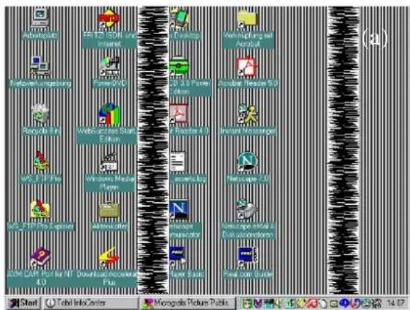

Figure 17 Burst test pattern applied to desktop showing problems with (a) pixel clock setting, (b) pixel phase setting.
6.3 Setup of a new Video Mode
The RGB to DVI(/VGA) Converter is preinstalled with several video modes and screen resolutions in various refresh rates suitable for using with an RGB source. If the mode generated by your RGB graphic source is not represented, you need to Setup a custom mode. The steps are similar to 6.2 Setup Instructions for RGB Input. Your custom mode is stored automatically and can be used in the same way as the preinstalled modes.
- Display from your graphic source a picture with as much detail as possible. If possible, display a ‘burst-pattern’ (see Figure 17) - a picture with alternating, 1-pixel wide, black and white, vertical stripes.
If you are unable to view the test card, display some black text on a white background. For example, you could open Notepad, maximize it to full screen, and fill the page with letter 'I's in a 12pt sans serif font. Proceed with step 2.
-
Display the OSD (see page 23).
-
Select the Scale Mode Menu (Physical Resolution of attached Screen – see page 29) and select the size of your used monitor (resolution must be equal or higher than the resolution, generated by your graphic card)
-
Select the Output Scaling Submenu (see page 30). Select NO SCALING - Mode (1:1)
-
Select the Video Mode Submenu (see page 35). Try-out all available modes and select the best matching one (all rows and all columns of your screen picture are displayed)
-
Select the Image menu option (see page 32)
-
Select the command icon: Automatic detection of number of pixels per line and the best phase.

-
The picture size may have been changed! Assess the desktop test pattern. If the vertical stripes are sharp and without jitter or smearing, the adjustment has been successful. Go to step 12.
-
If the picture quality is not acceptable after the automatic adjustment, you will have to manually adjust the pixel clock and pixel phase (in this order).
-
With a poorly adjusted pixel clock you may see one or more vertical areas, where the lines are smeared (see Figure 17a on page 39):
a. In the Image menu option (see page 32) select the command icon: Manually adjust the number of pixels per line (Pixel clock)
b. Adjust the pixel clock value until all stripes have disappeared.
c. Confirm the setting.

- Problems with the pixel phase will cause horizontal noise, horizontal wave-formed lines, flicker or smearing with zebra-pattern (see Figure 17b on page 39):
a. In the Image menu option (see page 32) select the command icon: Manually adjust the best phase (best point for A/D conversion within each pixel).
b. Modify the phase until all distortions have disappeared.
c. Confirm the setting.
- If necessary, adjust the position of the visible part of the screen. (Image menu option - see page 32)

- If necessary, adjust the size of the visible part of the picture. (The horizontal and vertical size is displayed in numeric values for exact adjustment).

- Select the Output Scaling Submenu (see page 30). Select the desired Scaling Mode
- If appropriate, re-attach your TFT monitor and adjust its image according to the manufacturer's instructions.
7. Troubleshooting
7.1 Video
There isn't a picture.
Check the power supply connection at the RGB to DVI(/VGA) Converter. Is the Device Ready (Red LED) illuminated (see page 21)? If not, the internal power-supply may be damaged or there may be an internal error.
Check if the Monitor detect LED is illuminated (see page 21)? If not, there may be a problem with the Interconnection cable.
Check that you are using a supported video mode (see Appendix D: Supported Video Modes). At the RGB to DVI(/VGA) Converter, is the Video Signal LED illuminated (see page 21)? If not, do you need to Setup a new video mode? (see Setup of a new Video Mode on page 38)?
The green LED is blinking
This problem normally occurs only with RGsB Signals if you have long coaxial cables, EMI noisy environment, high current power cables nearby or glitches from old graphic cards.
For Video Signals with HS< app. 20kHz, try to select 15kHz Glitch Filter to ON in Image Menu (Refer to page 32)
For Video Signals with HS> app. 20kHz, try to deselect Threshold Checking (OFF) in Image Menu (Refer to page 32)
After several seconds (minutes) intermittent loss of picture
This problem normally occurs only with RGsB Signals if you have long coaxial cables, EMI noisy environment, high current power cables nearby or glitches from old graphic cards.
For Video Signals with HS< app. 20kHz, try to select 15kHz Glitch Filter to ON in Image Menu (Refer to page 32)
For Video Signals with HS> app. 20kHz, try to deselect Threshold Checking (OFF) in Image Menu (Refer to page 32)
I Can't access to the OSD because of intermittent loss of picture
Disconnect the input signals from the Video Source. Wait until the message „No Signal detected“ appears. Now you can access to the OSD and make your settings. After doing the setup, reconnect the signal source.
There is horizontal jitter on the picture.
The pixel clock and/or phase is misaligned: Refer to page 36.
Characters are smeared.
The phase is misaligned: Refer to page 36.
Thin vertical lines are missing.
The phase is misaligned: Refer to page 36.
No output to a connected CRT or TFT with VGA input.
First connect your VGA monitor cable to the adapter and then plug in the adapter to the device. Otherwise, the VGA mode is not detected, DVI output is generated and there is no picture on the screen (See also Diagnostic LEDs on page 21).
Alternatively do a power-cycle with the device, while the screen stays attached.
There are parts of the picture missing.
The picture size is incorrect: refer to page 38 (Setup of a new Video Mode).
Appendix A: Example Applications
This section illustrates some specific applications using the RGB to DVI(/VGA) Converter:
For more details, please discuss suitable converter architecture with Technical Support (see Appendix E: Calling Technical Support).

Figure 18 RGB to DVI(/VGA) Converter attached to a PLC
![graph TD A["Computer monitor"] -->|USB| B["EGA/CGA"] B --> C["Server with VGA port"]](/content/2026/05/1091549/images/004dddd4982c7aa1be038fe51e26fdb070ffcedafa6325110b019b0beb248c92.jpg)
K238-3F
RGB to DVI(/VGA) Converter with optional EGA/CGA support, attached to an old fashioned Computer
Figure 19 RGB to DVI(/VGA) Converter with optional EGA/CGA support, attached to an old fashioned Computer
Appendix B: Rack Mount Options
RGB to DVI(/VGA) Converters can be mounted in a 19" rack using the mounting kit: DVI-KVM-Rackmount Kit
This contains the following parts:

Figure 20 Rack Mounting Kit
To mount a unit:
- Align the holes on the base plate with the vacant screw holes on the base of the RGB to DVI(/VGA) Converter unit.
- Fasten the base of the unit to the plate of the mounting kit using the supplied screws.
- Close the remaining gaps with blanking plates.
The kit allows you to mount various combinations of regular and double width housings:
- One regular unit (using two small plates) 2. Two regular units (using one small plate)


- Mounting of three regular units 4. Mounting of one double width unit (using wide plate)
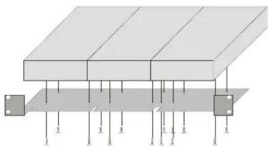

- Mounting of double width and regular units ( using narrow strip)

Appendix C: System Upgrade
System Update / Onboard Programming
It is occasionally necessary to update the firmware of the system. Normally, this procedure is carried out in the factory. If you want to update the firmware yourself, contact Technical Support. You will need a programming cable and software to carry out the update. Please follow the supplied instructions carefully.
Appendix D: Supported Video Modes
The following table shows the video modes originally supported by the Converter.
| Video Mode | Video Mode Resolution | Refresh Rates | Pixel- | |||
| Name | Horiz | Vertical (H)ert | Horizont. (kHz) | clock | ||
| 3 | MONA | S5 | 442 | 416 | 54,4 | |
| 0 | AS 230 / 235 / OS 252 | 448 | 288 | 50,0 | 15,6 | 10,0 |
| 7 | GBE 3977 - 64x32 | 448 | 288 | 50,0 | 15,6 | 10,0 |
| 1 | WF 470 | 512 | 240 | 49,1 | 15,6 | 12,0 |
| 2 | WF 470 neu | 512 | 245 | 50,1 | 15,6 | 12,0 |
| 1 | WF 470 / AS 215 | 512 | 256 | 50,1 | 15,6 | 12,0 |
| 2 | WF 470 / AS 215 | 512 | 512 | 50,0 | 31,3 | 24,0 |
| 5 | GEM 80 graph i | 560 | 224 | 50,0 | 15,6 | 11,8 |
| 5 | GEM 80 graph i | 560 | 224 | 60,0 | 15,8 | 11,8 |
| 5 | GEM 80 graph i | 560 | 224 | 75,0 | 18,2 | 12,0 |
| 8 | GBE 3977 - 80x48 | 560 | 288 | 50,0 | 15,6 | 13,0 |
| 10 | DISET - 80x25 | 560 | 288 | 50,0 | 15,6 | 12,2 |
| 1 | MONA-C | 560 | 413 | 58,2 | 25,8 | 20,0 |
| 5 | GEM 80 graph progr. | 560 | 448 | 50,0 | 31,3 | 23,5 |
| 5 | GEM 80 graph progr. | 560 | 448 | 60,0 | 31,5 | 23,7 |
| 5 | GEM 80 graph progr. | 560 | 448 | 75,0 | 36,4 | 24,0 |
| 2 | WF 480 | 580 | 480 | 60,0 | 30,6 | 25,0 |
| 0 | CGA | 640 | 200 | 60,0 | 15,8 | 14,2 |
| 6 | CP526/527 | 640 | 234 | 50,1 | 15,4 | |
| 4 | IVE1 | 640 | 284 | 50,0 | 15,7 | 12,3 |
| 6 | GEM 80 text | 640 | 288 | 48,8 | 15,6 | 13,0 |
| 1 | Prokon 2 | 640 | 288 | 83,1 | 27,4 | |
| 1 | EGA (TTL) | 640 | 350 | 59,9 | 21,9 | 16,3 |
| 2 | DOS graphic Mode | 640 | 350 | 70,0 | 31,4 | 25,1 |
| 0 | Vesa Standard | 640 | 350 | 85,0 | 37,9 | 31,5 |
| 1 | IVE3 | 640 | 379 | 50,0 | 21,8 | 17,3 |
24,
13,1
| Video Mode | Video Mode Resolution | Refresh Rates | Pixel- | |||
| Mode | Name | Horiz | Vertical (W)rt | Horizont. (kHz) | clock | |
| 1 | IVE4 | 640 | 385 | 50,0 | ||
| 1 | IVE2 | 640 | 398 | 50,0 | ||
| 0 | VGA | 640 | 400 | 56,0 | ||
| 1 | OP 398 K | 640 | 400 | 60,0 | 27,5 | 22,2 |
| 0 | VGA | 640 | 400 | 70,0 | ||
| 1 | Vesa Standard | 640 | 400 | 85,0 | 37,8 | 31,5 |
| 1 | COROS LS-C | 640 | 405 | 59,1 | 25,4 | 21,8 |
| 1 | Prokon 1 | 640 | 432 | 53,8 | 25,5 | 23,0 |
| 1 | Prokon 3 | 640 | 432 | 59,0 | 27,4 | 23,0 |
| 1 | CP 526 highres. 50 Hz | 640 | 468 | 50,0 | 31,2 | 26,2 |
| 1 | CP 526 highres. 60 Hz | 640 | 468 | 60,0 | 30,9 | 26,2 |
| 3 | CP 528 highres. 60 Hz | 640 | 468 | 60,0 | 30,9 | 28,3 |
| 1 | WF 480 / Gracis | 640 | 480 | 59,9 | 30,6 | 27,6 |
| 0 | Vesa Standard | 640 | 480 | 60,0 | 31,5 | 25,2 |
| 2 | MAC Mode | 640 | 480 | 66,7 | 35,0 | 31,4 |
| 0 | Vesa Standard | 640 | 480 | 72,8 | 37,9 | 31,5 |
| 0 | Vesa Standard | 640 | 480 | 75,0 | 37,5 | 31,5 |
| 0 | Vesa Standard | 640 | 480 | 85,0 | 43,3 | 36,0 |
| 1 | NEC | 642 | 200 | 60,0 | ||
| 1 | Std.- VGA | 656 | 496 | 59,9 | 31,5 | 25,2 |
| 4 | NTSC (halfline) | 680 | 240 | 60,0 | 15,7 | 12,9 |
| 3 | NTSC Interlaced | 720 | 240 | 60,0 | 15,8 | 13,5 |
| 3 | PAL Interlaced | 720 | 288 | 50,0 | 15,6 | 13,5 |
| 1 | ABB DSAV110 | 720 | 336 | 50,0 | 17,9 | 15,5 |
| 1 | ABB DSAV111 | 720 | 336 | 61,2 | 21,8 | 19,7 |
| 1 | Hercules monochrom | 720 | 350 | 49,8 | 18,4 | 16,3 |
| 1 | DOS Text Mode | 720 | 400 | 70,0 | 31,4 | 28,3 |
| 2 | Vesa Standard | 720 | 400 | 85,0 | 37,9 | 35,5 |
| 2 | VDU 2000 Coros | 720 | 405 | 59,1 | 25,4 | 24,5 |
| 1 | Teleperm / DS 078 | 720 | 408 | 60,0 | 25,7 | 23,1 |
| 3 | NTSC progressive | 720 | 480 | 60,0 | 31,5 | 27,0 |
| 3 | PAL progressive | 720 | 576 | 50,0 | 31,3 | 27,0 |
| 3 | PC-Textmode | 738 | 414 | 70,1 | 31,5 | 28,3 |
| 2 | MTBI | 746 | 246 | 60,0 | 15,7 | 14,1 |
| 2 | CP 527/ 60 | 800 | 468 | 59,9 | 30,9 | 32,7 |
| 4 | Vesa Standard | 800 | 600 | 56,2 | 35,1 | 36,0 |
| 0 | Vesa Standard | 800 | 600 | 60,3 | 37,9 | 40,0 |
| 0 | Vesa Standard | 800 | 600 | 72,1 | 48,0 | 49,9 |
| 0 | Vesa Standard | 800 | 600 | 75,0 | 46,9 | 49,5 |
| 0 | Vesa Standard | 800 | 600 | 85,0 | 53,6 | 56,2 |
| Video | Video Mode Resolution Refresh Rates Pixel- | |||||
| Mode | Name | Horiz | Vertical (Hz)rt | Horizont. (kHz) | clock | |
| 1 | MAC Mode | 832 | 624 | 75,0 | ||
| 0 | Vesa Standard | 1024 | 768 | 60,0 | 48,4 | 65,0 |
| 0 | Vesa Standard | 1024 | 768 | 70,0 | 56,4 | 74,9 |
| 1 | SUN Mode | 1024 | 768 | 72,0 | 58,0 | 75,2 |
| 0 | Vesa Standard | 1024 | 768 | 75,0 | 60,0 | 78,7 |
| 0 | Vesa Standard | 1024 | 768 | 85,0 | 68,7 | 94,5 |
| 2 | Industrie Standard (I) | 1024 | 768 | 87,0 | 35,5 | 44,9 |
| 11 | DISET oversample | 1120 | 288 | 50,0 | 15,6 | 24,5 |
| 1 | DMT1185 | 1152 | 864 | 70,0 | 63,5 | 100,1 |
| 0 | Vesa Standard | 1152 | 864 | 75,0 | 67,5 | 108,0 |
| 1 | SUN Mode | 1152 | 900 | 66,7 | 62,5 | 95,5 |
| 9 | GBE 3977 oversample | 1164 | 288 | 50,0 | 15,6 | 26,0 |
| 1 | TV Mode | 1280 | 768 | 60,0 | 48,1 | 81,2 |
| 0 | Vesa Standard | 1280 | 960 | 60,0 | 60,0 | 108,0 |
| 1 | DMT127A | 1280 | 960 | 75,0 | 75,0 | 126,0 |
| 0 | TV Mode | 1280 | 1024 | 50,1 | 53,4 | 90,1 |
| 0 | Vesa Standard | 1280 | 1024 | 60,0 | 64,0 | 108,0 |
| 1 | SUN Mode | 1280 | 1024 | 66,7 | 71,7 | 117,0 |
| 1 | SXGA Unix | 1280 | 1024 | 73,0 | 77,2 | 131,0 |
| 0 | Vesa Standard | 1280 | 1024 | 75,0 | 80,0 | 135,0 |
49,5
Appendix E: Calling Technical Support
If you determine that your RGB to DVI(/VGA) Converter is malfunctioning, do not attempt to alter or repair it. It contains no user-serviceable parts. Contact Technical Support.
Before you do, make a record of the history of the problem. We will be able to provide more efficient and accurate assistance if you have a complete description, including:
- The firmware-revision level printed on the bottom of the RGB to DVI(/VGA) Converter (very important):
Version Number Format:
Board: xxLO/RE Myyy Pzzz Auuu Gvvvvvv
Firmware: C/M/S xx Pyy Mzz
• The nature and duration of the problem.
- When the problem occurs.
- The results of any testing you’ve already done.
- The components involved in the problem—that is, what type of graphic source, what type, make and model of monitor, type and make of cable, etc.
- Any particular application that, when used, appears to create the problem or make it worse.
To solve some problems, it might be necessary to upgrade the RGB to DVI(/VGA) Converter's firmware. If this turns out to be the case for your difficulty, our Technical Support technicians will arrange for you to receive the new firmware and will tell you how to install it.
Shipping and Packaging
If you need to transport or ship your RGB to DVI(/VGA) Converter:
• Package it carefully. We recommend that you use the original container.
- If you are shipping it for repair, please include the Unit's external power supply. If you are returning it, please include everything you received with it. Before you ship the RGB to DVI(/VGA) Converter back to your dealer for repair or return, contact him to get a Return Material Authorization (RMA) number.
Appendix F: Specifications
Power Requirements
| Voltage | PSU: 90..240VAC-0.5A-47..63Hz/6VDC-2000 mA |
| Power required | RGB to DVI(/VGA) Converter: approx. 8W |
Interface
(Depending on type of device)
| Monitor | VGA (res.: 1280x1024@75Hz, plug&play supported)DVI (res.: 1280x1024@60Hz, plug&play supported) |
| Colour Depth | 15 Bit for converting to DVI/VGA (5 Bit per colour) |
| Bandwidth | 165 MHz |
| RGB/RGBS | 0,7Vpp for color signals without Sync, 1Vpp for GREEN (with Sync), 0,7Vpp for composite Sync |
| CGA/EGA | TTL for colours and Sync |
| FBAS / Composite | 1Vpp composite video signal |
| Y/C | 0,7Vpp for luminance signal and chrominance |
Size and Shipping Weight
| RGB to DVI(/VGA) Converter | 6.7"x5.2"x1.7" (170x133x44mm)Weight: 2.2lb (1.0kg) each |
| Shipping box | Shipping Box: 18.1"x9.8"x4.7" (460x250x120mm)Weight: 9.5lb (4.3kg) |
Environmental
| Operating Temperature | 41 to 113°F (5 to 45 °C) |
| Storage Temperature | -13 to 140°F (-25 to 60 °C) |
| Relative Humidity | max. 80% non-condensing |
Appendix G: Connectors and Cables
RGB to DVI(/VGA) Converter Connector Pinouts
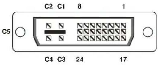
DVI-I Female connector (for Input and Output)

| Pin | Signal | Pin | Signal | Pin | Signal | |
| 1 | T.M.D.S data 2-9 | T.M.D.S | data 1-17 | T.M.D.S data 0- | ||
| 2 | T.M.D.S data 2+10 | T.M.D.S | data 1+18 | T.M.D.S data 0+ | ||
| 3 | T.M.D.S data 2 GND | 11 T. | M.D.S data 1 GND | 19 T.M.D.S | data 0 GND | |
| 4 | n.c. | 12 n.c. | 20 n.c. | |||
| 5 | n.c. | 13 n.c. | 21 n.c. | |||
| 6 | DDC Input (SCL) | 14 +5V | Power 22 | T.M.D.S clock GND | ||
| 7 | DDC Output(SDA) | 15 GND | 23 T.M.D.S clock + | |||
| 8 | Analog VSYNC | 16 Hot Plug recognition | 24 | T.M.D.S clock - | ||
| C1 | Analog Red | C3 | Analog Blue | |||
| C2 | Analog Green | C5 Analog GND | C4 | Analog HYSNC |
Programming

| Pin | Signal | |||
| 1 | TxD (to PC RxD) | |||
| 2 | RxD | (from | PC | TxD) |
| 3 | DTR | from | PC | |
| 4 | GND | |||
Power

| Pin | Signal |
| 1 | GND |
| 2 | Earth |
| 3 | n.c. |
| 4 | +6VDC |
| Housing | Shield |
Adapter Cables
DVI/VGA Adapter
RGB to DVI(/VGA) Converter: Monitor: DVI-I male connector HD15 female connector
Pin Signal Pin
| 6 DDC Input (SCL) | 15 DDC Input (SCL) |
| 7 DDC Output(SDA) | 12 DDC Output (SDA) |
| 8 Analog VSYNC | 14 Analog VSYNC |
| C1 Analog Red | 1 Analog Red |
| C2 Analog Green | 2 Analog Green |
| C3 Analog Blue | 3 Analog Blue |
| C4 Analog HYSNC | 13 Analog HSYNC |
| C5 Analog GND | 6,7,8 Analoc |

Signal

- WELCOME TO THE RGB TO DVI(/VGA) CONVERTER FAMILY
- COPYRIGHTS AND TRADEMARKS
- DISCLAIMER
- CAUTIONS AND NOTES
- EUROPEAN UNION DECLARATION OF CONFORMITY
- SAFETY PRECAUTIONS AND INSTALLATION GUIDELINES
- CONTENTS
- QUICK SETUP 8
- OVERVIEW 11
- INSTALLATION 17
- DEVICE CONTROL 22
- MONITOR SETUP 34
- RGB TO DVI(/VGA) CONVERTER SETUP 35
- TROUBLESHOOTING 40
- QUICK SETUP
- 1.1 VIDEO INPUT/OUTPUT
- 1.2 COMMAND SUMMARY
- OVERVIEW
- 2.1 INTRODUCTION
- 2.2 GLOSSARY
- THE RGB TO DVI(/VGA) CONVERTER
- 2.3 FEATURES
- OPTIONAL ACCESSORIES
- 2.4 PRODUCT RANGE
- 2.5 COMPATIBILITY
- INTERFACE COMPATIBILITY
- SUPPORTED SYNC FORMS
- 2.6 HOW TO USE THIS GUIDE
- CONNECTION & COMPATIBILITY
- ADJUSTING THE RGB TO DVI(/VGA) CONVERTER TO RGB VIDEO
- ADJUSTING THE MONITOR TO THE RGB TO DVI(/VGA) CONVERTER
- INSTALLATION
- 3.1 PACKAGE CONTENTS
- 3.2 CONNECTION CABLE REQUIREMENTS
- 3.3 SYSTEM SETUP
- 3.4 DIAGNOSTIC LEDS
- DEVICE CONTROL
- 4.1 OPENING THE OSD
- USING THE IR-RC
- FOR DIRECT BRIGHTNESS ADJUST FOR DIRECT CONTRAST ADJUST
- RESET TO FACTORY DEFAULTS
- TO NAVIGATE WITHIN THE OSD
- USING OUR WINDOWS™ PROGRAM
- 4.2 USING THE OSD
- INPUT SELECT
- SCALE MODE
- BRIGHTNESS - CONTRAST
- COLOR
- IMAGE
- TOOLS
- INPUT SELECT (FOR FUTURE EXPANSION)
- PHYSICAL RESOLUTION OF ATTACHED SCREEN
- OUTPUT SCALING
- BRIGHTNESS/CONTRAST
- SELECT COLORS AND COLOR TEMPERATURES
- COLOR TEMPERATURE
- FIGURE 12 TOOLS MENU
- OSD
- FACTORY RESET
- AUTO CONFIGURATION
- VIDEO MODE
- MONITOR SETUP
- RGB TO DVI(/VGA) CONVERTER SETUP
- 6.1 OVERVIEW
- 6.2 SETUP INSTRUCTIONS FOR RGB INPUT
- 6.3 SETUP OF A NEW VIDEO MODE
- TROUBLESHOOTING
- 7.1 VIDEO
- THERE ISN'T A PICTURE
- THE GREEN LED IS BLINKING
- AFTER SEVERAL SECONDS (MINUTES) INTERMITTENT LOSS OF PICTURE
- I CAN'T ACCESS TO THE OSD BECAUSE OF INTERMITTENT LOSS OF PICTURE
- THERE IS HORIZONTAL JITTER ON THE PICTURE
- CHARACTERS ARE SMEARED
- THIN VERTICAL LINES ARE MISSING
- NO OUTPUT TO A CONNECTED CRT OR TFT WITH VGA INPUT
- THERE ARE PARTS OF THE PICTURE MISSING
- APPENDIX A: EXAMPLE APPLICATIONS
- K238-3F
- APPENDIX B: RACK MOUNT OPTIONS
- APPENDIX C: SYSTEM UPGRADE
- SYSTEM UPDATE / ONBOARD PROGRAMMING
- APPENDIX D: SUPPORTED VIDEO MODES
- APPENDIX E: CALLING TECHNICAL SUPPORT
- SHIPPING AND PACKAGING
- APPENDIX F: SPECIFICATIONS
- INTERFACE
- APPENDIX G: CONNECTORS AND CABLES
- PROGRAMMING
- POWER
- ADAPTER CABLES
- DVI/VGA ADAPTER
Brand : Smart-AVI
Model : RGB2VGA
Category : Video Converter