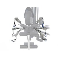
GT/X Functional Cable Arm - Fitness Equipment BodyCraft - Free user manual and instructions
Find the device manual for free GT/X Functional Cable Arm BodyCraft in PDF.


| Product Type | Functional Cable Arm Attachment |
| Brand | BodyCraft |
| Model | GT/X Functional Cable Arm |
| Compatible With | BodyCraft GT/X Home Gym Systems |
| Main Functions | Lat pulldowns, rows, tricep pushdowns, bicep curls, cable crossovers |
| Weight Capacity | Up to 200 lbs (90 kg) per side |
| Dimensions (L x W x H) | 48 x 12 x 6 inches (122 x 30 x 15 cm) approx. |
| Weight | 25 lbs (11.3 kg) |
| Material | Heavy-duty steel frame with powder coat finish |
| Cable Type | Aircraft-grade steel cable with nylon coating |
| Pulley System | Sealed ball bearings for smooth operation |
| Attachments Included | Ankle strap, V-grip bar, straight bar, lat bar |
| Mounting Type | Bolt-on to existing GT/X frame |
| Power Source | None (manual operation) |
| Maintenance | Wipe clean with damp cloth; lubricate pulleys every 6 months |
| Safety Features | Safety stop pins, adjustable pulleys with locking knobs |
| Spare Parts Available | Cables, pulleys, handles, mounting brackets |
| Repairability | Replacement parts available; user-replaceable cables |
| Warranty | Lifetime frame, 1 year parts |
Frequently Asked Questions - GT/X Functional Cable Arm BodyCraft
User questions about GT/X Functional Cable Arm BodyCraft
0 question about this device. Answer the ones you know or ask your own.
Ask a new question about this device
Download the instructions for your Fitness Equipment in PDF format for free! Find your manual GT/X Functional Cable Arm - BodyCraft and take your electronic device back in hand. On this page are published all the documents necessary for the use of your device. GT/X Functional Cable Arm by BodyCraft.
USER MANUAL GT/X Functional Cable Arm BodyCraft
GT Strength Training System

natural_image
Technical line drawing of a mechanical exercise machine (no text or symbols present)To see in FULL COLOR & additional information, scan this QR code.


natural_image
Technical line drawing of a mechanical exercise machine with blue frame and articulated arm (no text or symbols)Shown with Available Options:
GT-FCA (Functional Cable Arms), GT-LP (Leg Press),
S-Trainer-1 (Speed Trainer)
See Page 10 for option details
Base Serial Number: ____
Purchased Date: ____ / ____ / ____
Dealer's Name:
Please register your products at:
https://www.bodycraft.com/product-registration/


natural_image
Mechanical fitness equipment diagram showing arm and legs assembly (no text or labels)Owner's Manual
GT-X_OM_v1.8

WWW.BODYCRAFT.COM

800-990-5556

SERVICE@BODYCRAFT.COM
Congratulations and Welcome to the BODYCRAFT Family
Thank you for selecting BODYCRAFT. Your choice reflects a wise investment in you and your facility. We hope you use it for many healthy years!
BODYCRAFT offers a complete array of high-quality fitness equipment. Please refer to our website at www.bodycraft.com to view more ways to enhance your lifestyle.
Your BODYCRAFT machine has all the quality and design elements to make your workout extremely efficient and comfortable. Your new unit is a serious strength training machine that will keep you motivated, challenged and within reach of your fitness goals. Strength & cardiovascular training is vital for all ages which will provide an effective workout, producing results that will encourage you to reach your fitness goals and maintain the body you have always wanted.
Spending 15 to 30 minutes a day, three times a week, is all you need to start seeing the benefits of a regular exercise program.
As a premium exercise equipment manufacturer, we are committed to your complete satisfaction. If you have questions, suggestions or find missing or damaged parts, we guarantee your complete satisfaction through our authorized dealer network or by contacting us directly. Please call your local dealer or BODYCRAFT.
BODYCRAFT (a division of Recreation Supply, Inc.)
7699 Green Meadows Dr.
Lewis Center, OH 43035
Phone: 800-990-5556 9 am - 5 pm EST Email: service@bodycraft.com
Proof of purchase must be supplied to validate warranty and the product must have been registered with BODYCRAFT via online at www.bodycraft.com or by calling 800-990-5556 or 740-965-2442 M-F 9 a.m. - 5 p.m. EST.
For parts orders, owner's manuals, software update files, exercise guides and contact information scan this QR code.
Or go to:
https://www.bodycraft.com/customer-support


Table of Contents - GT 1 of 2

NOTE: When you have downloaded the Owner's Manual into a PDF reader, go directly to the desired page by touching any BLUE line in this Table of Contents.
Product Safety Information
Page
Product Safety 5
Important Notes, Recommended Tools & Cleaners ....6
Warning Labels, Maintenance Schedule - Details....7
Warning Labels, Maintenance Schedule - Placements 8
Product Overview
Machine Options - FCA, Leg Press & S-Trainer 9
Machine Dimensions, Room Layouts ......10
Weight Ratios - GT, FCA & LP 11
Assembly Parts & Hardware List.... 12 - 14
Shipping Box & What's Inside 15
Product Assembly - How to Assemble the GT
Pre-Assembly Tips ....16
STEP 1 - STEP 4....17 - 27
STEP 5 - Weight Stack w/ Optional 200 lbs Stack .....28 - 31
STEP 6 - Top Cable #36 ...... 32 - 41
STEP 7 - Ab Crunch Cable #37 ......42 - 47
STEP 8 - Lower Cable #38 ....48 - 51
STEP 9a - Final Assembly Lube Guide Rods .....52
STEP 9b - Weight Stack Covers & Accessories....53
STEP 9c - Optional Speed Trainer....54
Table of Contents - GT 2 of 2

NOTE: When you have downloaded the Owner's Manual into a PDF reader, go directly to the desired page by touching any BLUE line in this Table of Contents.
Product Assembly - How to Assemble the GT
Page
STEP 10 - Adjust the Cables for Correct Tension .....55
STEP 11 - Weight Stack Stickers Installation ....56
STEP 12 - Final Assembly Lube, Clean Up, & Polish....57
Maintenance & Repairs
Routine Schedule 58
General & Cable Inspections ....59
Lubrication Maintenance ....60
Strength Cable Wear Indicators 61
Detailed Parts Exploded View....62 - 64
Detailed Parts List 65 - 68
Required Info BEFORE Initiating a Service Case ....69
Warranty
Product Warranty 70
Product Warranty Registration 71
Contact Us Information 72
Product Safety - Functional Trainers, Duals & Multi-Gyms

There is a risk assumed by individuals who use this type of equipment. A moment's lack of attention can result in an accident, as can failure to observe certain simple safety precautions.
Read, study and understand the Assembly Instructions and all the warning labels on this product. Furthermore, it is recommended to familiarize yourself and others with the proper operation and workout recommendations for this BODYCRAFT product prior to use.

- Before beginning this or any other exercise program, consult your physician. This is especially important for individuals over the age of 35 or persons with preexisting health problems. Recreation Supply, Inc. assumes no responsibility for personal injury or property damage sustained by or through use of this product.
- Exercise with care to avoid injury. Do not attempt to lift more weight than you can control safely.
- This product must be assembled on a flat, level surface to assure its proper function.
- Clean pads and frame on a regular basis. We recommend warm, soapy water. Do not use harsh or abrasive chemicals.
- Inspect and tighten all parts before every use. Replace any worn parts immediately. Failure to do so may result in serious injury.
- Keep children away from any BODYCRAFT strength machines at all times.
- Keep your hands away from cables and pulleys during operation, other than the designated handles.
- Keep hands, limbs, loose clothing and long hair well out of the way of moving parts.
- Make certain all cables are seated within the pulleys before every use. Frayed or worn cables can be dangerous and may cause injury. Periodically check the cable for any indication of wear.
- Inspect the unit for any sign of wear on parts, hardware becoming loose or cracks on welds. If a problem is found, do not use or allow the machine to be used until the defective part is repaired or replaced.
- It is imperative that you retain this Assembly Instructions and be sure all warning labels are legible and intact. Replacement Assembly Instructions and labels are available from BODYCRAFT. If you are unsure about the proper use of the BODYCRAFT strength machine call your local BODYCRAFT dealer or our Customer Service Department. Contact BODYCRAFT at 800-990-5556 or support@bodycraft.com
Important Notes, Recommended Tools & Cleaners, GT
Important Notes and Tips:
- Before assembly, read all instructions thoroughly and preview diagrams to help make the installation easier.
- Make sure all parts are accounted for and in proper condition before beginning assembly. See the parts list.
-
Be cautious not to damage the flooring when assembling. Place a protectant down such as a rubber mat or shipping blanket.
-
Let plastics and weight stacks acclimate to room temperature before you begin assembly.
-
Two people are recommended for the safe assembly of this equipment.
-
Insert all bolts in the same direction when possible. Do not tighten until instructed.
-
Carefully install plastic caps using a rubber mallet.
-
When measuring bolt lengths, only measure the
-
When the installation is complete, be sure to regularly check for rust or damage, and perform preventative maintenance.

THE FOLLOWING TOOLS ARE RECOMMENDED FOR ASSEMBLY:

natural_image
Collection of metallic tool holders and a wrench, no visible text or symbolsSOCKET SET 3/8 DRIVE & 6" EXT (Only 1/2, 9/16, & 3/4 Sockets are needed)
natural_image
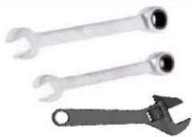
Three wrenches shown side by side: two standard wrenches and one adjustable wrench (no text or symbols visible)OPEN, CLOSED & ADJUSTABLE WRENCHES (Only 1/2, 9/16 & 3/4 are needed)
natural_image
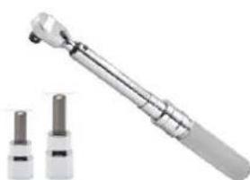
Close-up of a mechanical tool with two cylindrical components, one larger and one smaller, shown without any text or symbols.TORQUE WRENCH 3/8 DRIVE (w/ 5/32, 3/16, 1/4 & 3/8 Hex Bit Socket)

natural_image
Two types of metal tools: a wooden hanger and a yellow-handled tool with multiple pins (no text or symbols visible)RUBBER MALLET & ALLEN WRENCH SET (w/ 5/32, 3/16, 1/4 & 3/8 are needed)
THE FOLLOWING IS RECOMMENDED FOR CLEANING:
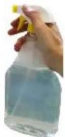
MILD CLEANING SOLUTION

natural_image
Two white sheets of paper, possibly folded paper or fabric, with no visible text or symbols.100% COTTON CLEANING CLOTHS
TIP ON FRAME ONLY: For extra protection from fingerprints, sweat stains or just plain dirt, apply an automotive grade cleaner wax if desired. Also makes future cleaning easier.
(Do Not Use on the Upholstery)

| MAINTENANCE SCHEDULE | ||||
| This checklist needs to be followed before any user starts to exercise. Please replace all parts at first signs of wear or damage. Do not use machine until repaired as needed. | DAILY | WEEKLY | MONTHLY | 12-MONTHS |
| Upholstery - Wipe down and dry. - Clean and condition. | X | X | ||
| Bolts, Nuts & Fasteners - Visually check they are secure & tighten if needed. - Tighten per Torque Specs (Semi-Annually if needed) | X | X | ||
| Cables - Visually check for any unusual bends, kinking, fraying plastic cover or ends coming loose. - Adjust cable tension and tighten the locking nut at weight stack. | X | X | ||
| Guide Rods & Seat Sleeves - Clean & Lubricate w/ virgin Silicone or Teflon tube. | X | |||
| Linear Bearing Guide Rods - Clean & Lubricate with Teflon (PTFE) grease. | X | |||
| Tightening Knobs Locking Pins Weight Stack Pins Pop Pins / Springs - Check all for functionality. | X | X | ||
| Warning Labels Anti-Skid Surfaces Hand Grips & Rollers - Inspect all above items for wear or if missing. | X | X | ||
| Frame & Chrome - Clean and dry. - Clean and Wax. | X | X | ||
(129b)
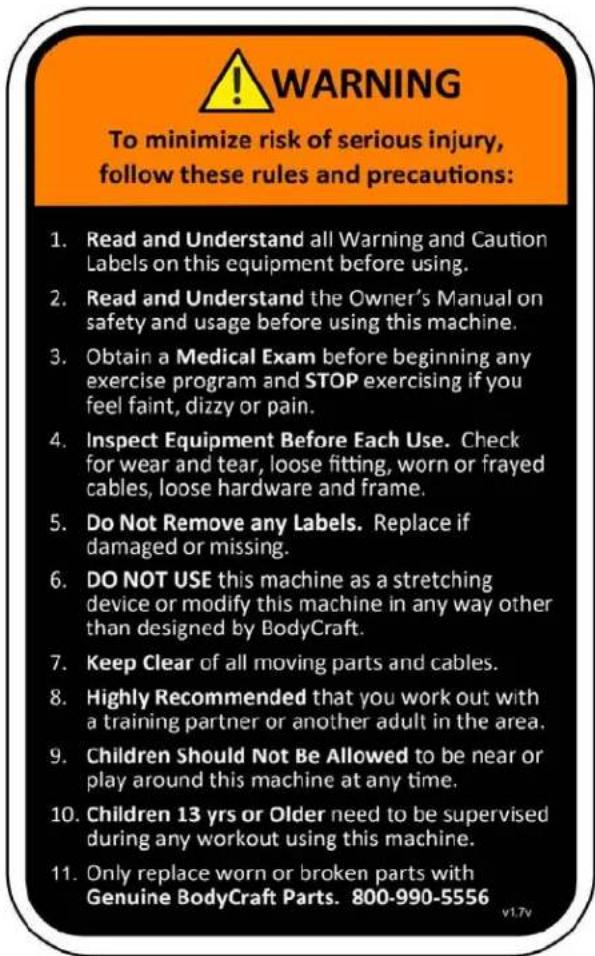
(122b)

(128b)
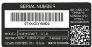
(130b)

(123b)

(124b)

(126b)
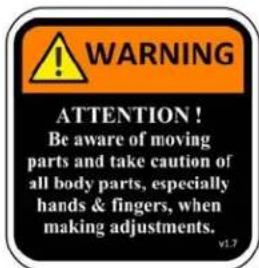
(125b)

(133b)
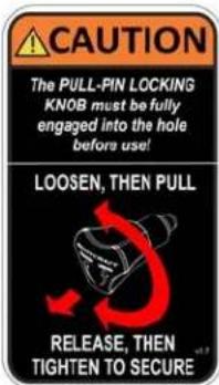
(127b)
Warning Labels, Maintenance Schedule & Serial Number Placement, GT / FCA / LP
Carefully read ALL warning, caution & maintenance schedule labels

Machine Options, GT
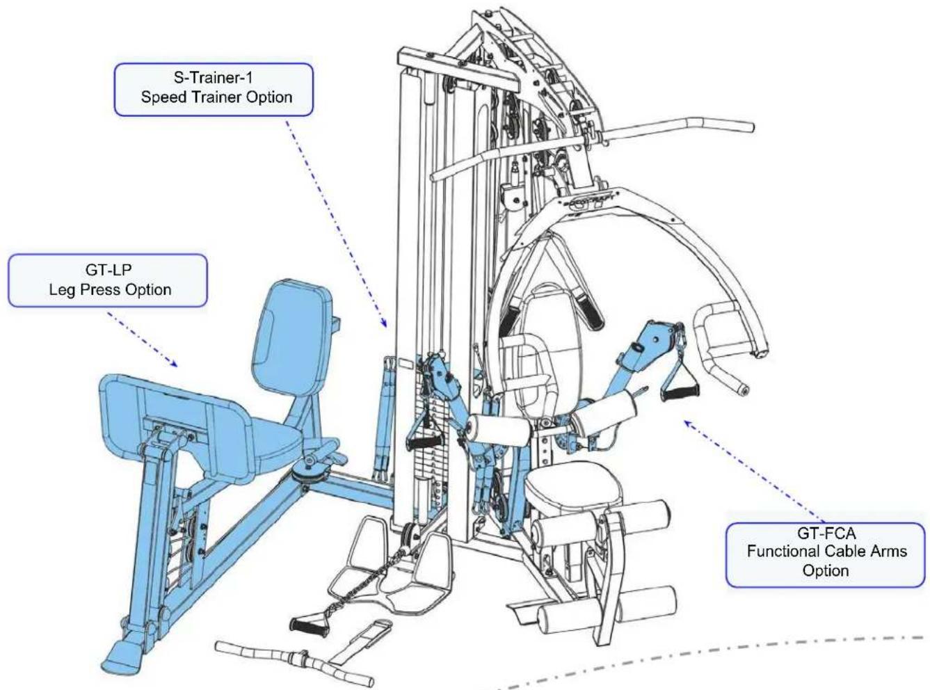
To install the GT-LP Leg Press/Calf Option, go directly to the GT Leg Press - Owner's Manual for assembly instructions.



natural_image
Technical illustration of a stationary exercise machine with adjustable legs and seat (no text or symbols)
To install the GT-FCA Functional Cable Arms Option, go directly to the GT Functional Cable Arms - Owner's Manual for assembly instructions.

natural_image
Mechanical robotic arm diagram showing articulated joints and linkages (no text or labels)
Machine Dimensions & Room Layouts, GT
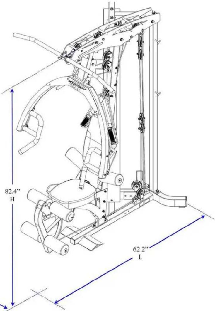
Your BODYCRAFT GT Strength Training System was designed to be placed in a corner.


ADA Compliant
For ADA Compliance under #1004 Exercise Machines and Equipment:
Minimum of 36" for entry, use & exit of machine required. Add 12" in the Training Area where needed.
GT Overall Dimensions
62.2"L × 53.9"W × 82.4"H
(158 cm L x 137 cm W x 209.3 cm H )
For additional Room Layouts on the GT Options go to:
GT Leg Press - Owner's Manual
GT Functional Cable Arms - Owner's Manual

10
Weight Stack Ratios, GT / FCA / LP

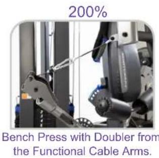

Leg Press with Hook attached for Turbo Feature
| Plate Number | Weight at 50% Ratio | Weight at 100% Ratio | Weight at 200% Ratio | Weight at 300% Ratio |
| 1 Top Plate | 5 lbs | 10 lbs | 20 lbs | 30 lbs |
| 2 | 10 lbs | 20 lbs | 40 lbs | 60 lbs |
| 3 | 15 lbs | 30 lbs | 60 lbs | 90 lbs |
| 4 | 20 lbs | 40 lbs | 80 lbs | 120 lbs |
| 5 | 25 lbs | 50 lbs | 100 lbs | 150 lbs |
| 6 | 30 lbs | 60 lbs | 120 lbs | 180 lbs |
| 7 | 35 lbs | 70 lbs | 140 lbs | 210 lbs |
| 8 | 40 lbs | 80 lbs | 160 lbs | 240 lbs |
| 9 | 45 lbs | 90 lbs | 180 lbs | 270 lbs |
| 10 | 50 lbs | 100 lbs | 200 lbs | 300 lbs |
| 11 | 55 lbs | 110 lbs | 220 lbs | 330 lbs |
| 12 | 60 lbs | 120 lbs | 240 lbs | 360 lbs |
| 13 | 65 lbs | 130 lbs | 260 lbs | 390 lbs |
| 14 | 70 lbs | 140 lbs | 280 lbs | 420 lbs |
| 15 | 75 lbs | 150 lbs | 300 lbs | 450 lbs |
| 16 | 80 lbs | 160 lbs | 320 lbs | 480 lbs |
| 17 | 85 lbs | 170 lbs | 340 lbs | 510 lbs |
| 18 | 90 lbs | 180 lbs | 360 lbs | 540 lbs |
| 19 | 95 lbs | 190 lbs | 380 lbs | 570 lbs |
| 20 | 100 lbs | 200 lbs | 400 lbs | 600 lbs |
NOTE: For a complete service parts list, please refer to the detailed parts list & exploded view at the rear of this manual.
| Part # | Assembly Parts List | QTY |
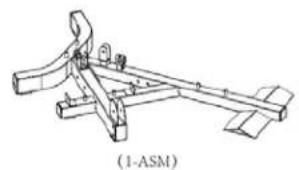
| GT-X-001-ASM | Frame, Bottom - Assembly w/ Serial # | 1 |
| GT-X-002-ASM | Frame, Connector, Top - Assembly | 1 |
| GT-X-003-ASM | Frame, Front, Upright - Assembly | 1 |
| GT-X-004 | Frame, Top | 1 |
| GT-X-005-ASM | Frame, Rear, Upright - Assembly | 1 |
| GT-X-006 | Guide Rod, 1" OD x 72-1/2" L, 3/8" nuts inserted & welded both ends | 2 |
| GT-X-007-ASM | Press Arm - Assembly | 1 |
| GT-X-011-ASM | Adjusting Frame for Seat Pad - Assembly | 1 |
| GT-X-012-ASM | Support Frame for Seat Pad - Assembly | 1 |
| GT-X-013-ASM | Leg Extension Arm, w/ Dual Holes for Different User Sizes - Assembly | 1 |
| GT-X-014-ASM | Limit Tube - Assembly | 2 |
| GT-X-015 | Adjusting Frame for Back Pad | 1 |
| GT-X-016-ASM | Connecting Frame for Press Arm - Assembly | 1 |
| GT-X-017 | Pulley Block, Double, Closed Flat End, Adjustable w/ 13 each | 1 |
| GT-X-018-ASM | Foot Plate for Low Row - Assembly | 1 |
| GT-X-019 | Pulley Block, Single Closed Flat End, w/ Cable End Threaded Shaft | 1 |
| GT-X-020 | Frame, Knee Hold Down | 1 |
| GT-X-022 | Stack Spacer, Tall, 7" for 150lb weight stack | 2 |
| GT-X-023 | Stack Spacer, Short, 3" for Optional 200lb weight stack | 2 |
| GT-X-024 | Metal Hinge to Seat Back Pad | 2 |
| GT-X-026 | Axle, for Press Arm, Lower, 20mm OD (solid w/ no flat notch) x 186mm L | 1 |
| GT-X-027 | Axle, for Leg Extension Arm, w/ one side flat notch, 12.7mm OD x 5/16" threaded ID x 67.5mm L | 1 |
| GT-X-028 | Axle, for Press Arm, Upper, 20mm OD x 3/8" threaded ID x 114mm L | 1 |
| GT-X-029 | Pad, Seat | 1 |
| GT-X-030-ASM | Pad, Back with BodyCraft Logo - Assembly | 1 |
| GT-X-036 | Cable, Top, 4,830mm (190.16") L | 1 |
| GT-X-037 | Cable, Ab Crunch, 4,230mm (166.5") L | 1 |
| GT-X-038 | Cable, Lower, 3,080mm (121.25") L | 1 |
| GT-X-040-ASM | Threaded Rod, between Top Connector Frame & Single Block Pulley (Not used with Leg Press) - Assembly | 1 |
natural_image
Technical line drawing of a mechanical clamp or bracket assembly (no text or symbols)
natural_image
Technical line drawing of a mechanical bracket assembly with two views (2-ASM), no text or symbols present

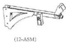
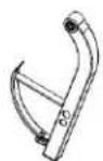
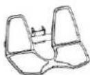
(13-ASM)

(14-ASM)

(15)

(16-ASM)

(17)
(18-ASM)

(19)

(20)

(36)

(40-ASM)
NOTE: Parts are not to scale
NOTE: For a complete service parts list, please refer to the detailed parts list & exploded view at the rear of this manual.
| Part # | Assembly Parts List | QTY |
| GT-X-041-ASM | Adjustable Stopper, for the Adjustable Pulley Block - Assembly | 1 |
| GT-X-043 | Spacer Sleeve, between Pulleys P5 & P16 on Top Frame | 1 |
| GT-X-046 | Weight Stack Shroud Cover | 2 |
| GT-X-047 | Pop-Pin, Aluminum , 55mm L (46mm) - BLUE | 1 |
| GT-X-048 | Pull-Pin Locking Knob, Aluminum - BLUE | 1 |
| GT-X-050 | Support Tube for 051 Rollers, Stainless Steel, 5/16" nuts inserted & welded on both ends | 2 |
| GT-X-051 | Roller, Upholstered Foam | 6 |
| GT-X-052 | Accessory, 48" Aluminum Lat Bar | 1 |
| GT-X-053 | Accessory, EZ-Curl/Low Row Bar | 1 |
| GT-X-054 | Accessory, Ankle Cuff (Leg Strap) | 1 |
| GT-X-055-ASM | Top Plate - Assembly | 1 |
| GT-X-056 | Selector Rod, 19 Holes | 1 |
| GT-X-059 | Rubber Cushion for Weight Stack | 2 |
| GT-X-061 | Accessory, Ab Crunch Strap | 1 |
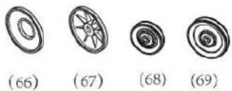
| GT-X-066 | End Cap for Upholstered Roller, Large Hole, Plastic - BLK | 6 |
| GT-X-067 | End Cap for Upholstered Roller, Small Hole, Plastic - BLK | 6 |
| GT-X-068 | Pulley, 90mm (3-1/2") x δ26mm ID | 22 |
| GT-X-069 | Pulley, 114mm (4-1/2") x δ26mm ID | 1 |
| GT-X-070 | Accessory, Single Handle | 1 |
| GT-X-071 | Pulley Block, Double | 1 |
| GT-X-076 | Bushing, Plastic, for Pulley to Frame, 3/8" ID | 8 |
| GT-X-077 | Bushing, Steel, for Upper Pulleys & Press Arm, 20mm ID | 8 |
| GT-X-079 | Snap Hook | 3 |
| GT-X-080 | Accessory, Chain, 19" L | 1 |
| GT-X-081 | Sticker, Weight Stack 1 - 20 | 1 |
| GT-X-118 | Weight Plate, 10lbs (4.5kg) ***(19 plates with 200lb upgrade)*** | 14 |
| GT-X-119 | Selector Pin w/ Lanyard, Aluminum - BLUE | 1 |
| GT-X-120 | Silicone Lube Bottle - for Guide Rods | 1 |
| GT-X-121 | Poster - Exercise Guide for GT Strength Training System | 1 |


natural_image
Three technical diagrams showing mechanical parts with numbered labels (54, 55, 56, 59), no readable text or symbols beyond labels.
natural_image
Four circular diagrams with spiral patterns, labeled (66) to (69), showing different geometric designs without any text or symbols.
(70)

(71)

(118)

(76)

(119)

(77)

(79)
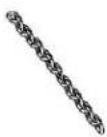
(80)

(81)

(120)

(121)
NOTE: Parts are not to scale
Assembly Parts - Hardware, GT 3 of 3
| Part # | Assembly Hardware | QTY |
| GT-X-083 | Washer, Spring, 5/16" - BLK | 8 |
| GT-X-084 | Washer, Spring, 3/8" - BLK | 12 |
| GT-X-085 | Washer, Spring, 1/2" - BLK | 4 |
| GT-X-086 | Washer, Flat, Large, φ8mm - BLK | 6 |
| GT-X-087 | Washer, Flat, Large, φ10mm - BLK | 4 |
| GT-X-088 | Washer, Flat, 1/2" - BLK | 12 |
| GT-X-089 | Washer, Flat, 3/8" - BLK | 62 |
| GT-X-090 | Washer, Flat, 5/16" - BLK | 8 |
| GT-X-093 | Bolt, Recessed Round Head, 7/16" x 1-3/4" L - BLK | 1 |
| GT-X-094 | Bolt, Recessed Round Head, 5/16" x 1-1/4" L - BLK | 6 |
| GT-X-097 | Bolt, Hex Head, 1/2" x 3-5/8" L - BLK | 1 |
| GT-X-098 | Bolt, Hex Head, 1/2" x 5-1/4" L - BLK | 2 |
| GT-X-099 | Bolt, Hex Head, 1/2" x 3" L - BLK | 2 |
| GT-X-100 | Bolt, Hex Head, 5/16" x 3/4" L - BLK | 2 |
| GT-X-101 | Bolt, Hex Head, 3/8" x 1" L - BLK | 6 |
| GT-X-102 | Bolt, Hex Head, 3/8" x 2" L - BLK | 16 |
| GT-X-103 | Bolt, Hex Head, 3/8" x 2-7/8" L - BLK | 4 |
| GT-X-104 | Bolt, Hex Head, 3/8" x 3" L - BLK | 5 |
| GT-X-105 | Bolt, Hex Head, 3/8" x 3-1/4" L - BLK | 2 |
| GT-X-106 | Bolt, Hex Head, 3/8" x 3-3/4" L - BLK | 2 |
| GT-X-107 | Bolt, Hex Head, 3/8" x 5" L - BLK | 4 |
| GT-X-108 | Screw, Recessed Flat Head, 5/16" x 3/4" L - BLK | 2 |
| GT-X-109 | Screw, Recessed Flat Head, 5/16" x 1/2" L - BLK | 4 |
| GT-X-115 | Nut, Nylon Lock, 3/8" - BLK | 27 |
| GT-X-116 | Nut, Nylon Lock, 1/2" - BLK | 7 |
| GT-X-134 | Wrench, Hex 3/16" | 1 |
| GT-X-135 | Wrench, Hex 3/8" | 1 |
| GT-X-136 | Washer, Spacer, Large, for bottom of Guide Rods, 50mm OD x 11mm ID x 5mm Thick - BLK | 2 |
| GT-X-137 | Wrench, Hex, 5/32" | 1 |
| GT-X-138 | Wrench, Hex, 1/4" | 1 |

(83)

(84)

(85)

(86)

(87)

(88)

(89)

(90)

(136)

(93)

(94)
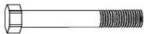
(97)

(98)
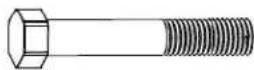
(99)

(102)

(100)
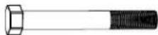
(103)

(101)

(104)
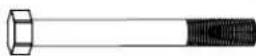
(105)

(106)

(107)

(108)

(109)

(115)

(116)

(134)
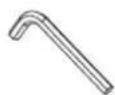
(135)

(137)

(138)
NOTE: Parts are not to scale
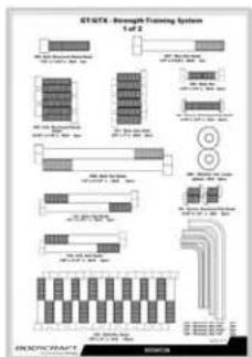
flowchart
graph TD
    A["STGTX Intrinsic Training System"] --> B["Memory"]
    A --> C["I/O"]
    A --> D["Electrical Wiring"]
    B --> E["Memory Block 1"]
    C --> F["Memory Block 2"]
    D --> G["Electrical Wiring"]
    E --> H["Output Line"]
    F --> I["Output Line"]
    G --> J["Output Line"]


Hardware Kits & Owner's Manual (Located inside box #1)
Large Box 1 of 2
Net Weight: 160.3 lbs (72.7 KGS)
Gross Weight: 185.6 lbs (84.2 KGS)
Box Size: 46.3" W x 42.1" L x 11.6" H (1,175mm W x 1,070mm L x 295mm H)

Medium Box 2 of 2
Net Weight: 131.4 lbs (59.6 KGS)
Gross Weight: 144.2 lbs (65.4 KGS)
Box Size: 75.4" W x 21.7" L x 6.9" H (1,915mm W x 550mm L x 175mm H)
Small Boxes
Net Weight: 70 lbs (31.7 KGS) ea.
Box Sizes: 6" W x 11" L x 8" H ea. (152.4mm W x 279.4mm L x 203.2mm H)
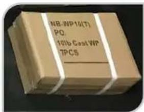
(Standard 150 lb Stack)


natural_image
Assorted mechanical and training equipment including tools, relays, and a body-craft model (no visible text or symbols on main objects)
natural_image
Collection of mechanical components and a BodyCRAFT GTIGTX Training System box on a white fabric mat (no text or symbols visible on parts)Upgraded to 200 lb Stack?
An additional box @ 50 lbs
BODYCRAFT reserves the right to make improvements at any time which may affect color, parts, materials, size, weight, or any other aspect.
PREASSEMBLY TIP #1 - "Stage Right".
During the assembly process we will be stating Right, Left, Front, Back, Top, or Bottom. These all are in the perspective of the user in the machine facing outward with feet on the ground.
See below images as examples.

natural_image
Stage performance with audience and a green checkmark overlay (no readable text or symbols)STAGE RIGHT DEFINITION: Both "Stage Right" or "Stage Left" are from the viewpoint of the actor facing outward from the stage.
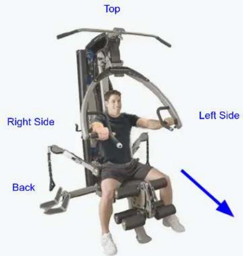
Front
PREASSEMBLY TIP #2 – Unpackaging & organizing.
The best practice in assembly is to take all the parts out of the boxes & bags and line up in order of assembly. This enables a mindset of what you will be assembling, their physical sizes and what challenges you might face BEFORE you begin.

natural_image
Assorted automotive component parts laid out on a wooden surface, including tools, motors, and wiring (no visible text or labels)PREASSEMBLY TIP #3 - Keep hardware loose until asked to tighten.
During the assembly, hardware needs to be finger tight until the STEPS of "Torque Time". This will ensure sub-frame and other parts will easily fit together and not strip out bolt threads during assembly.

Please Hand Tighten All Nuts & Bolts Until STEP 2a

STEP 1a - 1b: Install Uprights to Bottom & Top Frames


natural_image
Technical line drawing of two vertical metal supports with mounting brackets and support structures (no text or symbols)
CAUTION
Pinch Point
Keep hands clear of edges

View Keys
Red dotted (large): Structural parts assembled direction.
Red dotted (med): Sub-parts assembled direction.
Blue dotted lines (small): Hardware assembled direction.
Orange (med): Cables are normally black, but easier to see in color.
| Part # Assembly | Parts List QTY | |
| GT-X-001-ASM | Frame, Bottom - Assembly w/ Serial # 1 | |
| GT-X-003-ASM | Frame, Front, Upright - Assembly 1 | |
| GT-X-004 Frame | Top 1 | |
| GT-X-005-ASM | Frame, Rear, Upright - Assembly 1 |
| Part # Assembly Hardware QTY | |
| GT-X-085 Washer, Spring, 1/2" - BLK 2 | |
| GT-X-088 Washer, Flat, 1/2" - BLK 8 | |
| GT-X-099 Bolt, Hex Head, 1/2" x 3" L - BLK 2 | |
| GT-X-116 Nut, Nylon Lock, 1/2" - BLK 6 |


Please Hand Tighten All Nuts & Bolts Until STEP 2a
STEP 1c: Install Foot Plate


STEP 1d: Install Seat Support Frame &

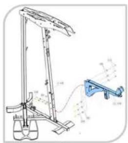

△CAUTION
Pinch Point
Keep hands clear of edges
| Part # Assembly | Parts List QTY | |
| GT-X-012-ASM | Support Frame for Seat Pad - Assembly 1 | |
| GT-X-018-ASM | Foot Plate for Low Row - Assembly 1 |
| Part # Assembly | Hardware QTY | |
| GT-X-084 Washer, Spring, 3/8" - BLK 2 | ||
| GT-X-089 Washer, Flat, 3/8" - BLK 12 | ||
| GT-X-104 Bolt, Hex Head, 3/8" x 3" L - BLK 5 | ||
| GT-X-106 Bolt, Hex Head, 3/8" x 3-3/4" L - BLK 2 | ||
| GT-X-115 Nut, Nylon Lock, 3/8" - BLK 5 | ||
STEP 2a: "Torque Time" on Main Frame Nuts & Bolts from STEP 1a - 1d
NOTE: These recommended torque specs should be followed for correct assembly and safe operation of this machine.

Example of being overtightened not using the recommended torque specs.

natural_image
Close-up of a mechanical component with red arrows pointing to features (no text or symbols visible)Tighten to torque specs to ensure the bolts and nuts do the following:
- Securely hold the frame and keep moving parts from coming loose during operation.
- Keep from crushing the frame.
- Avoid stripping the threads on either the bolts or nuts.
- Allow moving parts to adjust freely per the designed intent.

https://www.wikihow.com/Use-a-Torque-Wrench#Video

20 ft-lbs (+/- 2 lbs)
Tighten all 1/2" Nuts & Bolts to the recommended torque specs of 20 ft-lbs (+/- 2 lbs).
17 ft-lbs (+/- 2 lbs)
Tighten all 3/8" Nuts & Bolts to the recommended torque specs of 17 ft-lbs (+/- 2 lbs).
NOTE: Start at the bottom then work your way up to the top.
STEP 2b: Install Back Pad Adjusting Frame & Pull Pin

Fully tighten Pop-Pin with Adjustable Wrench.
Note: Fully tighten until the gap is closed. Then loosen, up to 1/8 turn so that the Adjusting Frame (15) will move but has no play.
| Part # Assembly | Parts List QTY | |
| GT-X-015 Adjusting Frame for Back Pad 1 | ||
| GT-X-047 Pop-Pin, Aluminum , 55mm L (46mm) - BLUE 1 | ||
| Part # Assembly | Hardware QTY | |
| GT-X-088 Washer, Flat, 1/2" - BLK 2 | ||
| GT-X-097 Bolt, Hex Head, 1/2" x 3-5/8" L - BLK 1 | ||
| GT-X-116 Nut, Nylon Lock, 1/2" - BLK 1 | ||

Recommended Tools


ADJUSTABLE WRENCH
DECISION POINT
GT - STEP 2c
If you are only assembling a GT
Strength Training System at this time:
Go to STEP 3a


natural_image
Technical line drawing of a mechanical lifting device with no visible text or symbolsIf you are simultaneously assembling the:
- GT Strength Training System
AND
- GT-FCA (GTX) Option

Please go directly to the
GT-FCA (GTX) Owner's
Manual to continue the
assembly GT-FCA (GTX),
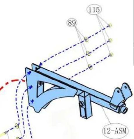
STEP 1a - 1e


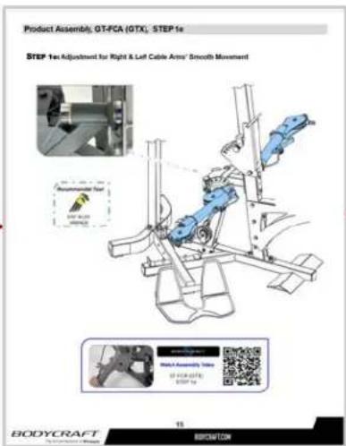
After STEP 1e in the
GT-FCA (GTX) Owner's
Manual come back to
GT- Owner's Manual to
GT-STEP 3a

Product Assembly, GT, STEP 3a
STEP 3a: Install Adjusting
Seat Frame & Seat Pad
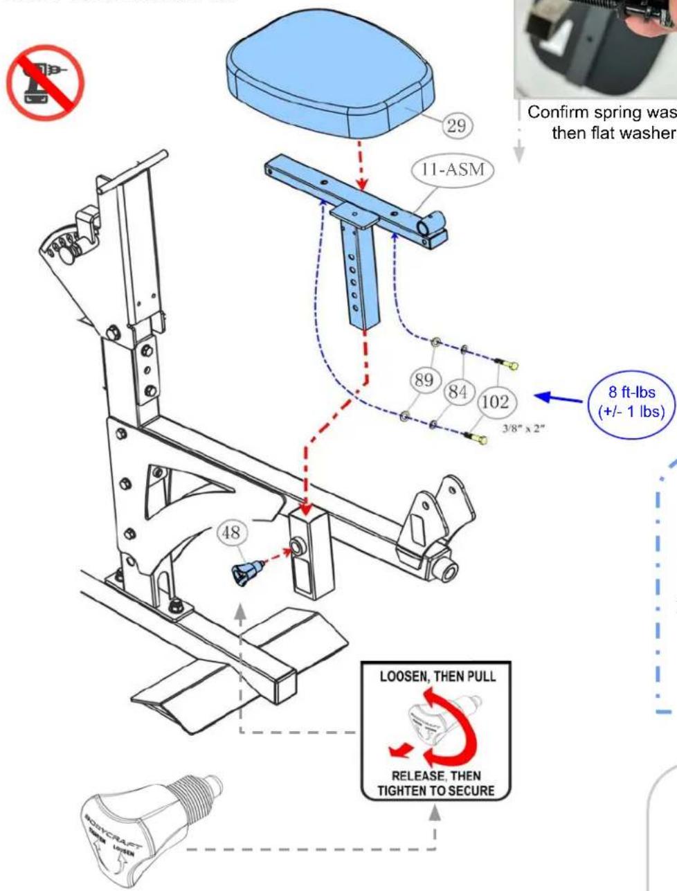
| Part # | Assembly Parts List | QTY |
| GT-X-011-ASM | Adjusting Frame for Seat Pad - Assembly | 1 |
| GT-X-029 | Pad, Seat | 1 |
| GT-X-048 | Pull-Pin Locking Knob, Aluminum - BLUE | 1 |
| Part # | Assembly Hardware | QTY |
| GT-X-084 | Washer, Spring, 3/8" - BLK | 2 |
| GT-X-089 | Washer, Flat, 3/8" - BLK | 2 |
| GT-X-102 | Bolt, Hex Head, 3/8" x 2" L - BLK | 2 |

natural_image
Hand holding a black threaded mechanical component, blurred background with no visible text or symbolsConfirm spring washer then flat washer.

natural_image
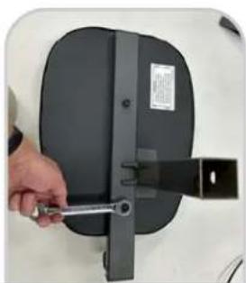
Hand holding a wrench next to a black rectangular device with a label (no visible text or symbols)TIP: Easier to install hardware when flipped upside down.
Recommended Tools:
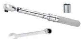
TORQUE WRENCH w/ 9/16 SOCKET & 9/16 WRENCH
Fully tighten at this time to the Recommended Torque Specs

STEP 3b: Install Leg Extension Arm & Knee Hold Down Frame

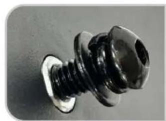
natural_image
Close-up of a black plastic screw with threaded base and cap (no text or symbols visible)Screw, spring washer then flat washer.

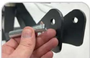
natural_image
Close-up of a hand holding a metal bracket component (no visible text or symbols)Flat notch through right side to left side.
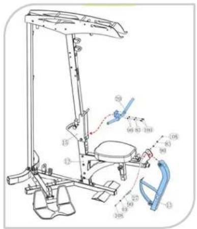

natural_image
Close-up of a hand holding a metallic mechanical component with a small screw (no visible text or symbols)Fully tighten at this time all hardware to the Recommended Torque Specs
| Part # Assembly | Parts List QTY | |
| GT-X-013-ASM | Leg Extension Arm, w/ Dual Holes for Different User Sizes - Assembly 1 | |
| GT-X-020 Frame | Knee Hold Down 1 | |
| GT-X-027 | Axle, for Leg Extension Arm, w/ one side flat notch, 12.7mm OD x 5/16" threaded ID x 67.5mm L | 1 |
| Part # Assembly | Hardware QTY | |
| GT-X-083 Washer, Spring, 5/16" - BLK 4 | ||
| GT-X-090 Washer, Flat, 5/16" - BLK 4 | ||
| GT-X-100 Bolt, Hex Head, 5/16" x 3/4" L - BLK 2 | ||
| GT-X-108 Screw, Recessed Flat Head, 5/16" x 3/4" L - BLK 2 | ||
DECISION POINT
GT - STEP 3c

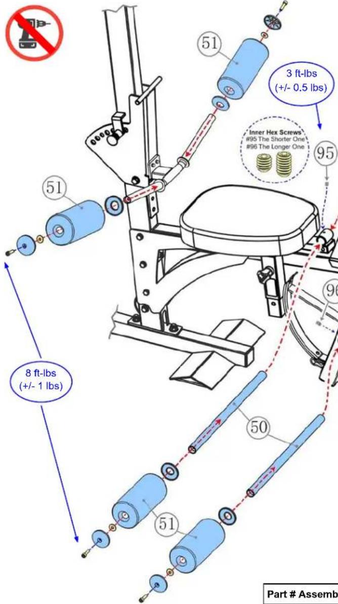
At the Leg Extension / Curl Station, the bottom set of Rollers (51) can be installed at either hole on the Leg Extension Arm (13-ASM). The Support Tube (50) can be installed in:
The top hole, which will accommodate shorter legs.
or
The bottom hole, which will accommodate longer legs.
It comes down to personal comfort while doing variety of leg exercises.
Preparing for STEP 3d: Roller Pads Installation

natural_image
Close-up of a black exercise machine with control buttons and a handle (no visible text or symbols)Easier to not forget any parts & shorten the assembly time, when laying out the next STEP parts in order to install.

natural_image
Close-up of a mechanical device with a metallic cylindrical component inserted into a black seat (no visible text or symbols)
natural_image
Close-up of a mechanical component with textured surface and circular base (no visible text or symbols)When assembled and tightened correctly, the roller pads should look like the image above.
Product Assembly, GT, STEP 3d
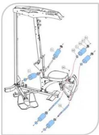
STEP 3d: Install Support Tubes & Rollers

natural_image
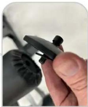
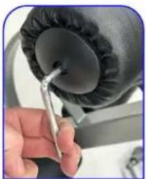
Close-up of a hand holding a black plastic clip with threaded pins (no visible text or symbols)Confirm washer is behind plastic cover.
natural_image
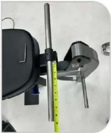
Close-up of a mechanical clamp or fixture with a yellow measuring tape, no visible text or symbolsMeasure to center Support Tubes

Fully tighten at this time to the Recommended Torque Specs
natural_image
Close-up of a hand using a tool to press or adjust a black circular object, no visible text or symbols| Part # Assembly | Parts List QTY | |
| GT-X-050 | Support Tube for 051 Rollers, Stainless Steel, 5/16" nuts inserted & welded on both ends | 2 |
| GT-X-051 Roller | Upholstered Foam 6 | |
| GT-X-066 End Cap | for Upholstered Roller, Large Hole, Plastic - BLK 6 | |
| GT-X-067 End Cap | for Upholstered Roller, Small Hole, Plastic - BLK 6 |
| Part # Assembly Hardware QTY | |
| GT-X-086 Washer, Flat, Large, φ8mm - BLK 6 | |
| GT-X-094 Bolt, Recessed Round Head, 5/16" x 1-1/4" L - BLK 6 | |
| GT-X-095 Screw, Inner Hex, 5/16" x 1/4" L - BLK 1 | |
| GT-X-096 Screw, Inner Hex, 5/16" x 1/2" L - BLK 1 |
STEP 4a - 4b: Install the Connecting Frame & Back Pad


natural_image
Close-up of a mechanical assembly with metal components and mounting brackets (no visible text or symbols)| Part # Assembly | Parts List QTY | |
| GT-X-016-ASM | Connecting Frame for Press Arm - Assembly 1 | |
| GT-X-024 Metal | Hinge to Seat Back Pad 2 | |
| GT-X-028 | Axle, for Press Arm, Upper, 20mm OD x 3/8" threaded ID x 114mm L | 1 |
| GT-X-030-ASM | Pad, Back with BodyCraft Logo - Assembly 1 | |
| GT-X-077 | Bushing, Steel, for Upper Pulleys & Press Arm, 20mm ID | 2 |
| Part # Assembly Hardware QTY | |
| GT-X-084 Washer, Spring, 3/8" - BLK 6 | |
| GT-X-087 Washer, Flat, Large, φ10mm - BLK 2 | |
| GT-X-089 Washer, Flat, 3/8" - BLK 4 | |
| GT-X-101 Bolt, Hex Head, 3/8" x 1" L - BLK | 6 |
Product Assembly, GT, STEP 4c
STEP 4c: Install the Press Arm Assembly

CAUTION: Press Arm Assembly (7-ASM) is large and awkward to install, especially to the Connecting Frame (16-ASM).
Find a friend to help with STEP 4b to ensure a happier and longer life during the rest of the assembly process!

natural_image
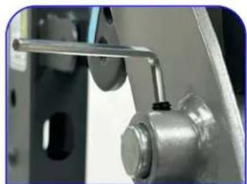
Close-up of a mechanical assembly with a blue background featuring the word 'BODYCRAFT' (no other visible text or symbols)Double CONFIRM the Press Arm Axle is centered before tightening the Inner Hex Screws

| Part # Assembly | y Parts List QTY | |
| GT-X-007-ASM | Press Arm - Assembly 1 | |
| GT-X-026 | Axle, for Press Arm, Lower, 20mm OD (solid w/ no flat notch) x 186mm L | 1 |
| Part # Assembly Hardware QTY | |
| GT-X-095 Screw, Inner Hex, 5/16" x 1/4" L - BLK 2 |
natural_image
Close-up of a mechanical assembly with metallic components and a lever (no visible text or symbols)Fully tighten at this time all hardware to the Recommended Torque Specs

STEP 5a Please ONLY Hand Tighten the Guide Rods, No Tools

CONFIRM the Large Spacer Washers are placed on the Main Frame over the welded-in bolts.

natural_image
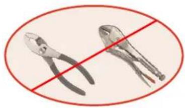
Close-up of a hand holding two metallic mechanical components (no visible text or symbols)Guide Rods have welded-in nuts and will need to be screwed tight by HAND onto Main Frame bolts.
natural_image
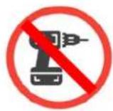
Two metal pliers crossed out by a red diagonal line, no text or symbols presentDO NOT USE Pliers or Locking Jaw Pliers

natural_image
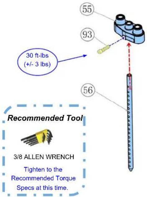
Technical line drawing of a mechanical device with no visible text or symbolsSTEP 5b: Install Selector Rod
| Part # Assembly | Parts List QTY | |
| GT-X-006 | Guide Rod, 1" OD x 72-1/2" L, 3/8" nuts inserted & welded both ends | 2 |
| GT-X-055-ASM | Top Plate - Assembly | 1 |
| GT-X-056 Selector Rod, 19 Holes 1 | ||
| Part # Assembly | Hardware QTY | |
| GT-X-136 | Washer, Spacer, Large, for bottom of Guide Rods, 50mm OD x 11mm ID x 5mm Thick - BLK | 2 |
| GT-X-093 Bolt, R | Recessed Round Head, 7/16" x 1-3/4" L - BLK 1 |

DECISION POINT
150 lb
GT - STEP 5c
Weight Stack
If you are installing the 150 lb Weight
Stack, use the 7" tall Stack Spacers (22).

OPTIONAL 200 lb Weight Stack
If you are installing the OPTIONAL 200 lb Weight Stack, use the 3" tall Stack Spacers (23).
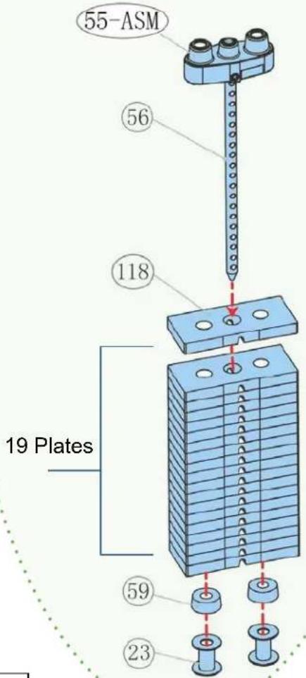
| Part # Assembly | Parts List QTY | |
| GT-X-022 Stack | Spacer, Tall, 7" for 150lb weight stack 2 | |
| GT-X-023 Stack | Spacer, Short, 3" for Optional 200lb weight stack 2 | |
| GT-X-055-ASM | Top Plate - Assembly 1 | |
| GT-X-056 Selector | or Rod, 19 Holes 1 | |
| GT-X-059 Rubber | Cushion for Weight Stack 2 | |
| GT-X-118 | Weight Plate, 10lbs (4.5kg) ***(19 plates with 200lb upgrade)*** | 14 |

CRITICAL: Align the selector holes on the weight plates forward, toward the front of the machine, with the half moon opening facing down. Confirm back side of weight stack should have NO holes showing. See image above.
STEP 5d: Lightly Lube Guide Rods
NOTE: Lightly lubing the Guide Rods is a great practice to do at this point due to:
- Doing this before the weight stack goes on and blocks the potential "dry" part of the Guide Rods, ensures they are lubed.
- Ensures that the Weight Plates internal bushing get a "break-in" lube for a quiet & longer life operation.
- Add protection to the Guide Rods (6) from future potential surface rust in the higher humidity environments.
STEP 5e: Install Stack Spacers, Rubber Cushions, Weight Plates, & Top Plate w/ Selector Rod

| Part # Assembly | Parts List QTY | |
| GT-X-022 Stack | Spacer, Tall, 7" for 150lb weight stack 2 | |
| GT-X-023 | Stack Spacer, Short, 3" for Optional 200lb weight stack | 2 |
| GT-X-055-ASM | Top Plate - Assembly 1 | |
| GT-X-056 Selector | Rod, 19 Holes 1 | |
| GT-X-059 Rubber | Cushion for Weight Stack 2 | |
| GT-X-118 | Weight Plate, 10lbs (4.5kg) ***(19 plates with 200lb upgrade)*** | 14 |

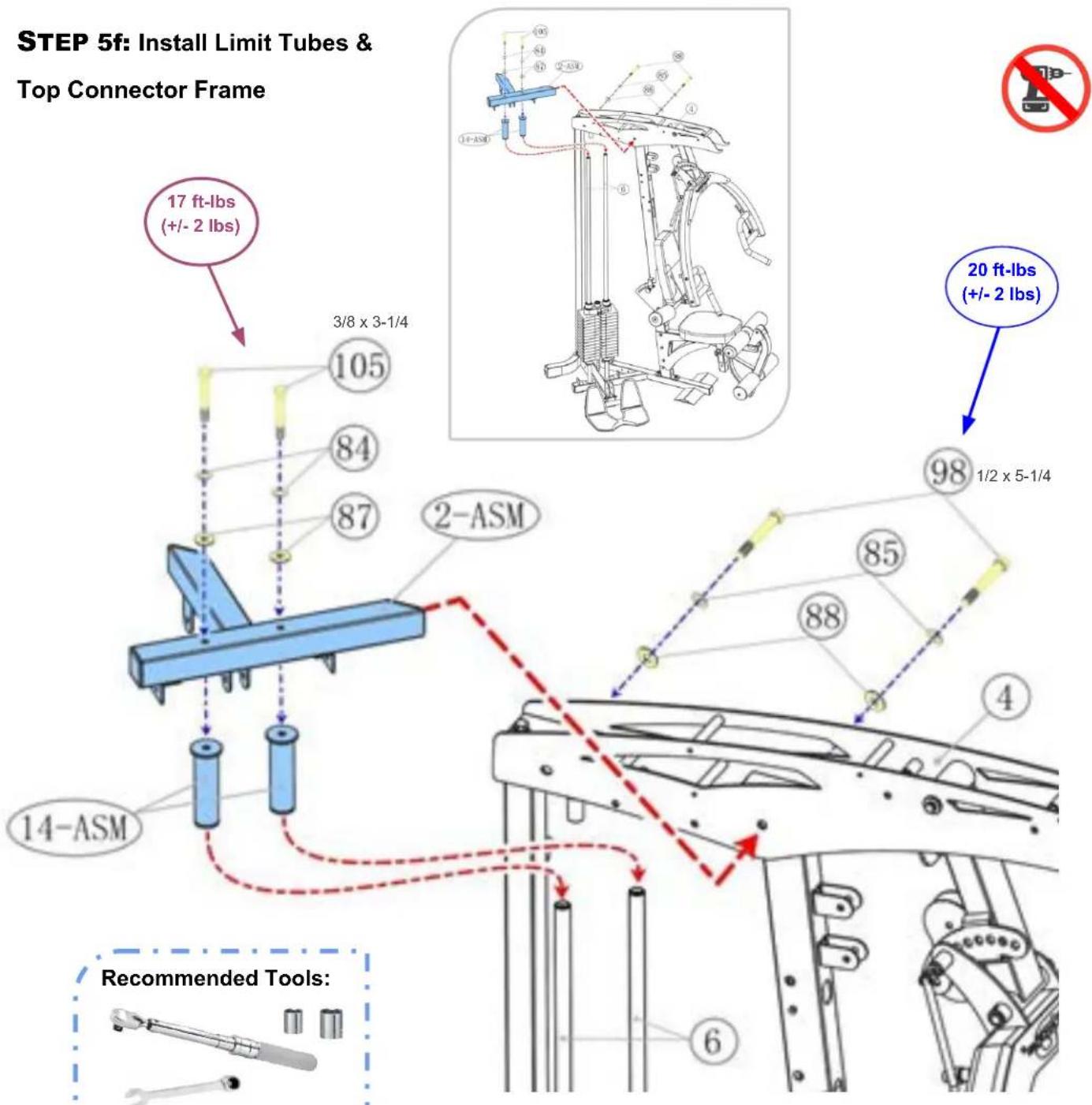

natural_image
Illustration of a wrench tool with multiple cylindrical components (no text or symbols)TORQUE WRENCH w/ 3/4, 9/16 SOCKETS & 3/4, 9/16 WRENCHES
Tighten to the Recommended Torque Specs at this time.
| Part # Assembly | Parts List QTY | |
| GT-X-002-ASM | Frame, Connector, Top - Assembly 1 | |
| GT-X-014-ASM | Limit Tube - Assembly 2 |
| Part # Assembly | Hardware QTY | |
| GT-X-084 Washer, Spring, 3/8" - BLK 2 | ||
| GT-X-085 Washer, Spring, 1/2" - BLK 2 | ||
| GT-X-087 Washer, Flat, Large, φ10mm - BLK 2 | ||
| GT-X-088 Washer, Flat, 1/2" - BLK 2 | ||
| GT-X-098 Bolt, Hex Head, 1/2" x 5-1/4" L - BLK 2 | ||
| GT-X-105 Bolt, Hex Head, 3/8" x 3-1/4" L - BLK 2 | ||
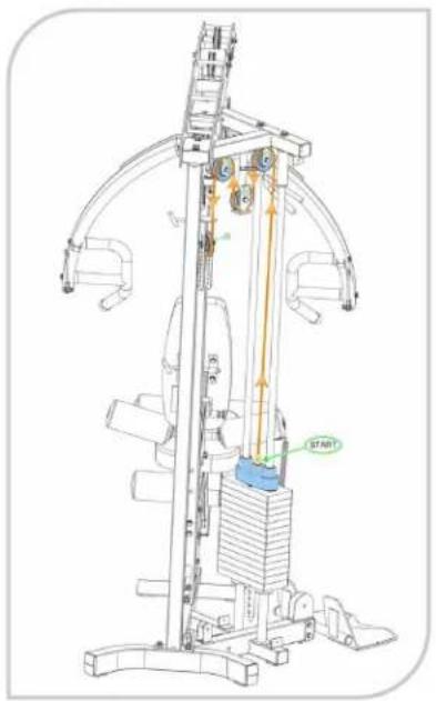
Product Assembly, GT, STEP 6 Top Cable #36 - OVERVIEW 1 of 2

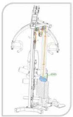
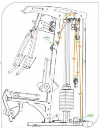
OVERVIEW IMAGE for STEP 6 (RIGHT SIDE) ... Start Assembly on page 34

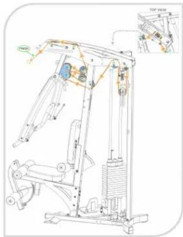
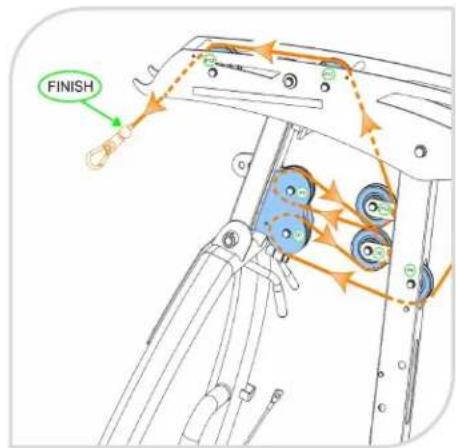
Pulleys are numbered w/ GREEN circles for installation routing.
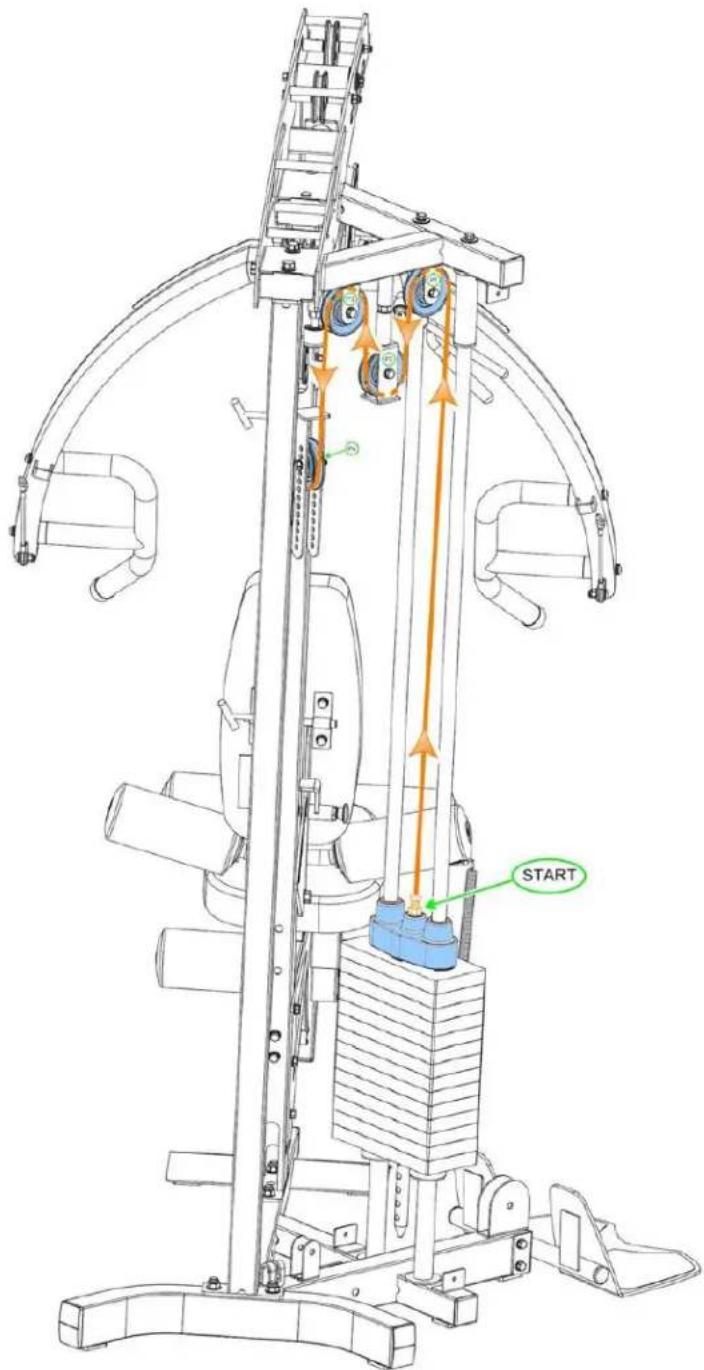
NOTE: Actual color of Top Cable #36 is black. Shown in the assembly STEPS in ORANGE for easy viewing
Product Assembly, GT, STEP 6 Top Cable #36 OVERVIEW 2 of 2
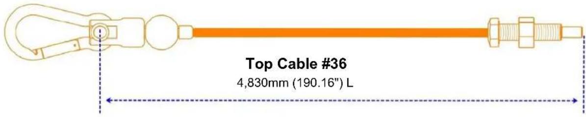
OVERVIEW IMAGE for STEP 6 (LEFT SIDE) ... Start Assembly on page 34

Product Assembly, GT, STEP STEP 6a & Optional SpeedTrainer
STEP 6a: Install Top Cable #36 to Top Plate


NOTE: Screw into top plate approximately halfway to allow for future adjustment.

| Part # Assembly Parts List QTY | |
| GT-X-036 Cable, Top, 4,830mm (190.16") L 1 | |
| GT-X-119 Selector Pin w/ Lanyard, Aluminum - BLUE 1 |

natural_image
Close-up of a mechanical component with metallic rods and a central hub (no visible text or symbols)
OPTIONAL Speed Trainer
If you are installing the OPTIONAL Speed Trainer, assemble at this time:
- Upper Hook Plate (403)
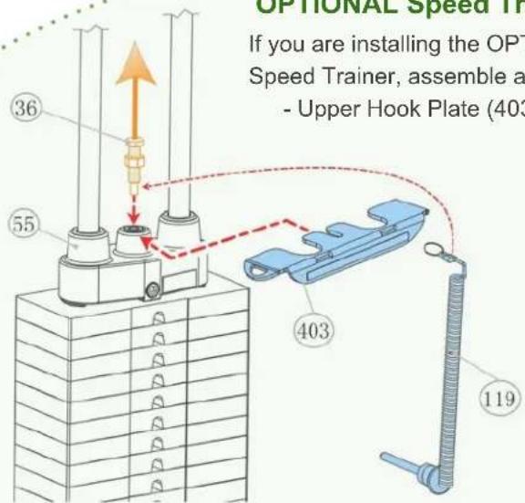

| Part # Detailed Parts List QTY | ||
| S-Trainer-403 | Hook Plate, Upper, to Weight Stack 1 | |
STEP 6b: Install Pulley P1

Please Hand Tighten All Nuts & Bolts Until STEP 6n

natural_image
Technical line drawing of a mechanical device with no visible text or symbolsRecommended Tool

ADJUSTABLE WRENCH
Screw in Threaded Rod or Adjustable Stopper 50% into the Upper Frame.
Tighten the Jam Nut at this time.
DECISION POINT
GT - STEP 6c
If you are only assembling a GT Strength Training System at this time, install:
- Threaded Rod #40-ASM
- Single Pulley Block #19
- Pulley P2 #68

OPTIONAL GT-LP
Leg Press
If you are installing the OPTIONAL
GT-LP Leg Press, use:
- Adjustable Stopper #221-ASM
- Single Pulley Block #19 (Flipped)
- Pulley P2 #68
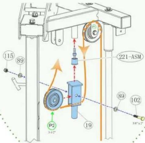
| Part # Assembly Parts List QTY | ||
| GT-X-019 | Pulley Block, Single Closed Flat End, w/ Cable End Threaded Shaft | 1 |
| GT-X-040-ASM | Threaded Rod, between Top Connector Frame & Single Block Pulley (Not used w/ Leg Press) - Assembly | 1 |
| GT-X-068 Pulley, 90mm (3-1/2") x 526mm ID 2 | ||
| GT-X-LP-221-ASM | Adjustable Stopper, for the Single Pulley Block - Assembly | 1 |
| Part # Assembly | Hardware QTY | |
| GT-X-089 | Washer, Flat, 3/8" - BLK | 4 |
| GT-X-102 | Bolt, Hex Head, 3/8" x 2" L - BLK | 2 |
| GT-X-115 | Nut, Nylon Lock, 3/8" - BLK | 2 |
STEP 6d: Install Pulley P3

Please Hand Tighten All Nuts & Bolts Until STEP 6n

STEP 6e: Install Adjustable Stopper, Double Pulley Block & Pulley P4

| Part # Assembly | Parts List QTY | |
| GT-X-017 Pulley | Block, Double, Closed Flat End, Adjustable w/ 13 each 1 | |
| GT-X-041-ASM | Adjustable Stopper, for the Adjustable Pulley Block - Assembly 1 | |
| GT-X-068 Pulley | 90mm (3-1/2") x δ26mm ID 2 |
| Part # Assembly Hardware QTY | |
| GT-X-089 Washer, Flat, 3/8" - BLK 4 | |
| GT-X-102 Bolt, Hex Head, 3/8" x 2" L - BLK 2 | |
| GT-X-115 Nut, Nylon Lock, 3/8" - BLK 2 |

Please Hand Tighten All Nuts & Bolts Until STEP 6n
STEP 6f - 6g: Install Pulleys P5 - P6


| Part # Assembly Parts List QTY | ||
| GT-X-068 Pulley, 90mm (3-1/2") x δ26mm ID 2 | ||
| GT-X-076 | Bushing, Plastic, for Pulley to Frame, 3/8" ID | 2 |
| Part # Assembly Hardware QTY | |
| GT-X-089 Washer, Flat, 3/8" - BLK 4 | |
| GT-X-103 Bolt, Hex Head, 3/8" x 2-7/8" L - BLK 1 | |
| GT-X-107 Bolt, Hex Head, 3/8" x 5" L - BLK 1 | |
| GT-X-115 Nut, Nylon Lock, 3/8" - BLK 2 |

Please Hand Tighten All Nuts & Bolts Until STEP 6n

STEP 6h - 6i: Install Pulleys P7 - P8

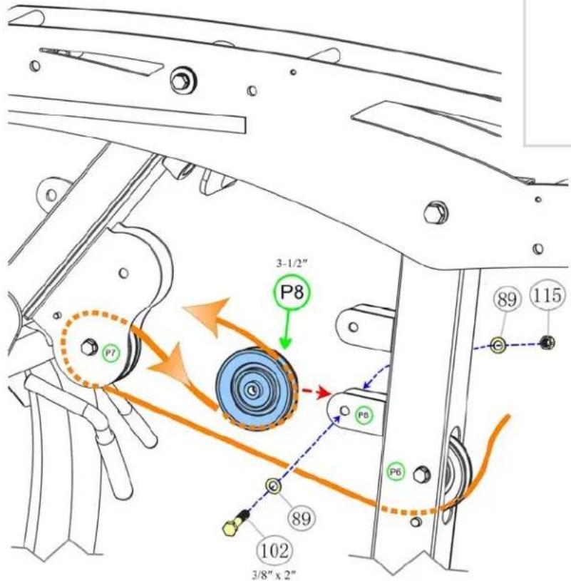
| Part # Assembly Parts List QTY | |
| GT-X-068 Pulley, 90mm (3-1/2") x δ26mm ID 2 |
| Part # Assembly Hardware QTY | |
| GT-X-089 Washer, Flat, 3/8" - BLK 4 | |
| GT-X-102 Bolt, Hex Head, 3/8" x 2" L - BLK 2 | |
| GT-X-115 Nut, Nylon Lock, 3/8" - BLK 2 |

Please Hand Tighten All Nuts & Bolts Until STEP 6n
STEP 6j - 6k: Install Pulleys P9 - P10

Product Assembly, GT, STEP 6l - 6m

Please Hand Tighten All Nuts & Bolts Until STEP 6n
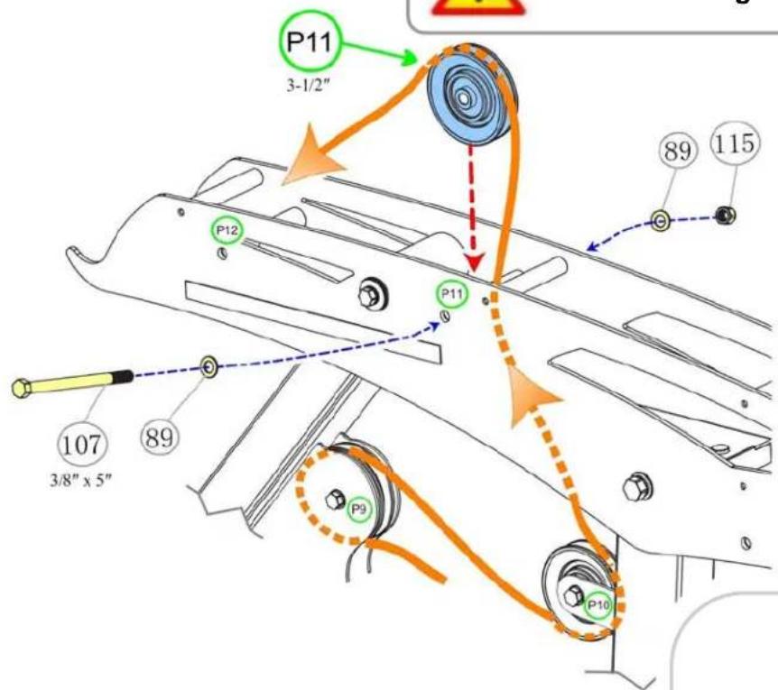
STEP 6I - 6m: Install Pulleys P11 - P12
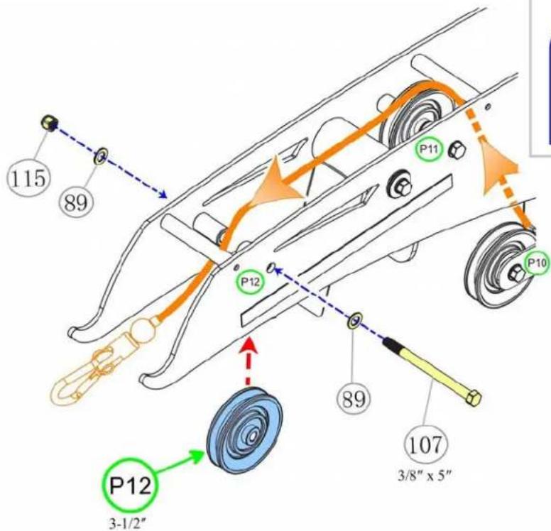

| Part # As | embly Parts List QTY | |
| GT-X-068 | Pulley, 90mm (3-1/2") x δ26mm ID 2 |
| Part # Assembly Hardware QTY | |
| GT-X-089 Washer, Flat, 3/8" - BLK 4 | |
| GT-X-107 Bolt, Hex Head, 3/8" x 5" L - BLK 2 | |
| GT-X-115 Nut, Nylon Lock, 3/8" - BLK 2 |
Product Assembly, GT, STEP 6n - "Torque Time"
STEP 6n: "Torque Time"
- Tighten the 3/8" Bolts from STEPS 6b to 6m to the recommended torque specs of 17 ft-lbs (+/- 2 lbs)
- The 3/8" Bolt with Plastic Bushings to the torque specs of 8 ft-lbs (+/- 1 lbs)


Product Assembly, GT, STEP 7 (Ab Cable #37) OVERVIEW
Ab Crunch Cable #37 for GT ONLY (not for use with GT-FCA Option) 4,230mm (166.5") L
OVERVIEW IMAGE for STEP 7 (w/o Options) ... Start Assembly on page 44

68
3-1/2"
Pulleys
P14 -
P18
Pulleys are numbered w/ GREEN circles for installation routing.

69
4-1/2"
Pulley
P13
Pulleys are numbered w/ GREEN circles for installation routing.
NOTE: Actual color of Ab Cable #37 is black. Shown in the assembly STEPS in ORANGE for easy viewing

Product Assembly, GT-FCA (GTX), STEP 2 (Ab Crunch Cable #310) - OVERVIEW
Ab Crunch Cable #310 for GT-FCA ONLY (not for use with GT ONLY)
4,630mm (182.28") L
OVERVIEW IMAGE for STEP 7 (w/ GT-FCA Options) ... Start Assembly on page 44

NOTE: Actual color of Ab Crunch Cable #310 is black. Shown in the assembly STEPS in ORANGE for easy viewing
STEP 7a - 7b: Install Ab Crunch Cable #37 and Pulleys P13 - P14


Please Hand Tighten All Nuts & Bolts Until STEP 7h
| Part # Assembly | Parts List QTY | |
| GT-X--037 | Cable, Ab Crunch, 4,230mm (166.5") L | 1 |
| GT-X-076 Bushing | Plastic, for Pulley to Frame, 3/8" ID 4 | |
| GT-X-068 Pulley | 90mm (3-1/2") x δ26mm ID 1 | |
| GT-X-069 Pulley | 114mm (4-1/2") x δ26mm ID 1 |
| Part # Assembly Hardware QTY | |
| GT-X-089 Washer, Flat, 3/8" - BLK 4 | |
| GT-X-103 Bolt, Hex Head, 3/8" x 2-7/8" L - BLK 2 | |
| GT-X-115 Nut, Nylon Lock, 3/8" - BLK 2 |

natural_image
Technical line drawing of a mechanical lifting device with no visible text or symbols
Please Hand Tighten All Nuts & Bolts Until STEP 7h
STEP 7c: Install Pulley P15
NOTE: Easier to install the Spacer Sleeve #43, if done in this order.
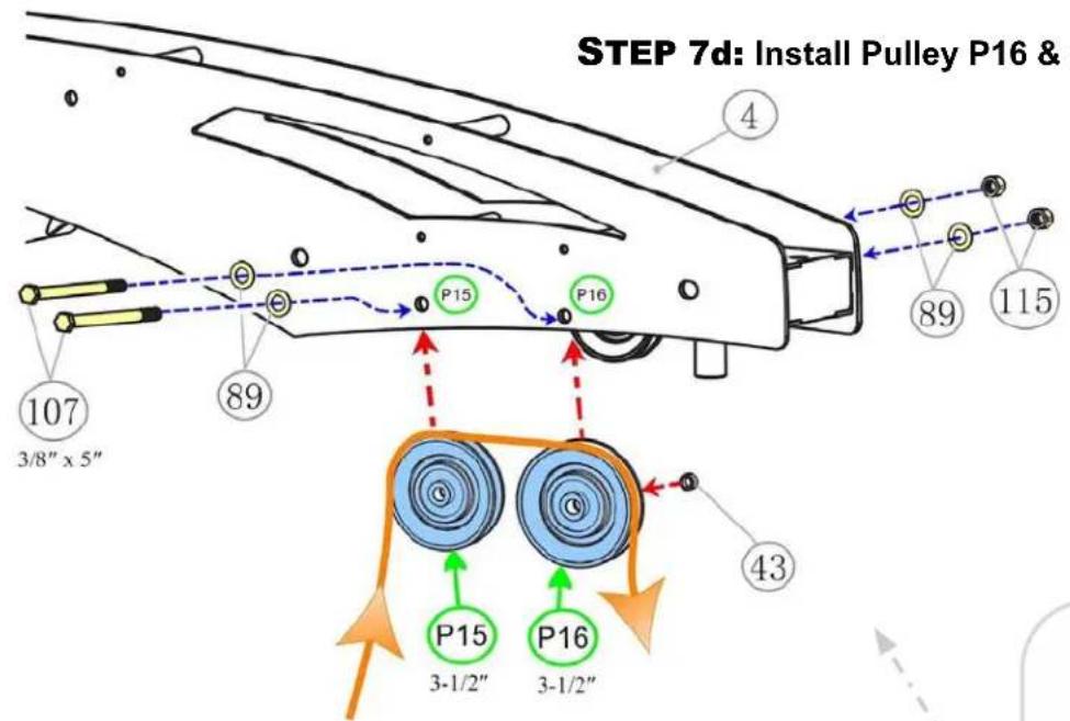
STEP 7d: Install Pulley P16 & Spacer Sleeve #43
TOP VIEW

| Part # Assembly | Parts List QTY | |
| GT-X-043 | Spacer Sleeve, between Pulleys P5 & P16 on Top Frame | 1 |
| GT-X-068 Pulley | 90mm (3-1/2") x δ26mm ID 2 |
| Part # Assembly Hardware QTY | |
| GT-X-089 Washer, Flat, 3/8" - BLK 4 | |
| GT-X-107 Bolt, Hex Head, 3/8" x 5" L - BLK 2 | |
| GT-X-115 Nut, Nylon Lock, 3/8" - BLK 2 |

Please Hand Tighten All Nuts & Bolts Until STEP 7h
STEP 7e - 7f: Install Pulleys P17 - P18

flowchart
graph TD
    A["17"] --> B["3/8" x 2""]
    C["89"] --> D["102"]
    E["115"] --> F["89"]
    G["71"] --> H["102"]
    I["P17 3-1/2""] --> J["Blue circular component"]
    K["P18 3-1/2""] --> L["Blue circular component"]
    M["P17"] --> N["Blue circular component"]
    O["P18"] --> P["Blue circular component"]
    Q["89"] --> R["Blue circular component"]
    S["102"] --> T["Blue circular component"]
| Part # Assembly | Parts List QTY | |
| GT-X-068 Pulley | 90mm (3-1/2") x δ26mm ID 2 | |
| GT-X-071 Pulley | Block, Double 1 |
| Part # Assembly Hardware QTY | |
| GT-X-089 Washer, Flat, 3/8" - BLK 4 | |
| GT-X-102 Bolt, Hex Head, 3/8" x 2" L - BLK 2 | |
| GT-X-115 Nut, Nylon Lock, 3/8" - BLK 2 |

STEP 7g : Install Cable to Main Frame (1-ASM)

Product Assembly, GT, STEP 7h - "Torque Time"
STEP 7h: "Torque Time"
- Tighten the 3/8" Bolts from STEP 7a - 7f to the recommended torque specs of 17 ft-lbs (+/- 2 lbs)
- The 3/8" Bolts with Plastic Bushings to the torque specs of 8 ft-lbs (+/- 1 lbs)

Product Assembly, GT, STEP 8 (Lower Cable #38) OVERVIEW
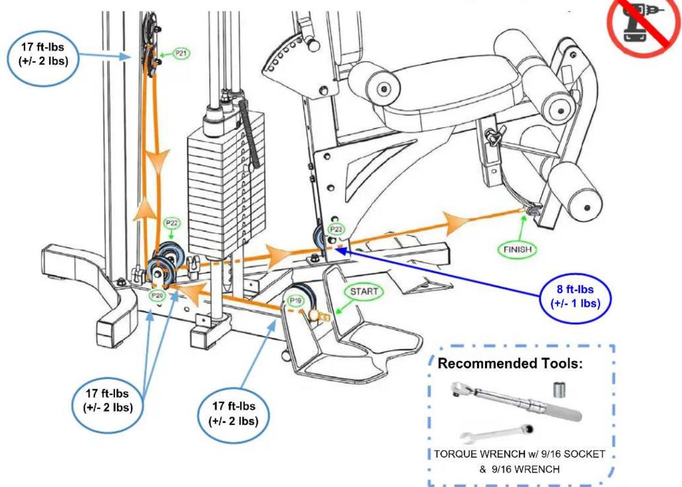
Lower Cable #38
3,080mm (121.25") L
OVERVIEW IMAGE for STEP 8 (RIGHT SIDE) ... Start Assembly on page 49
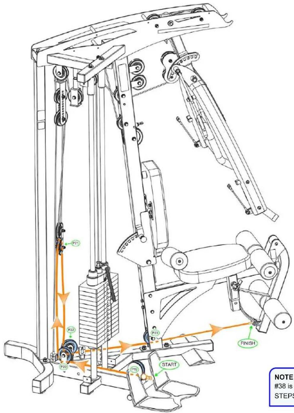

Pulleys are numbered w/ GREEN circles for installation routing.
NOTE: Actual color of Lower Cable #38 is black. Shown in the assembly STEPS in ORANGE for easy viewing

Please Hand Tighten All Nuts & Bolts Until STEP 8g
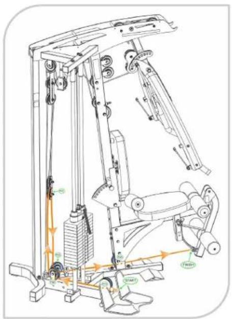
STEP 8a - 8b: Install Lower Cable #38 and Pulleys P19 - P20

| Part # | Assembly Parts List QTY | |
| GT-X-038 | Cable, Lower, 3,080mm (121.25") L | 1 |
| GT-X-068 | Pulley, 90mm (3-1/2") x δ26mm ID | 2 |
| Part # | Assembly Hardware QTY | |
| GT-X-089 | Washer, Flat, 3/8" - BLK | 4 |
| GT-X-102 | Bolt, Hex Head, 3/8" x 2" L - BLK | 2 |
| GT-X-115 | Nut, Nylon Lock, 3/8" - BLK | 2 |

Please Hand Tighten All Nuts & Bolts Until STEP 8g
STEP 8c: Install Pulley P21

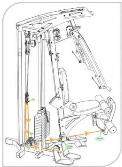
STEP 8d - 8e: Install Pulleys P22 - P23

| Part # Assembly Hardware QTY | |
| GT-X-089 Washer, Flat, 3/8" - BLK 6 | |
| GT-X-102 Bolt, Hex Head, 3/8" x 2" L - BLK 2 | |
| GT-X-103 Bolt, Hex Head, 3/8" x 2-7/8" L - BLK 1 | |
| GT-X-115 Nut, Nylon Lock, 3/8" - BLK | 3 |
| Part # Assembly Parts List QTY | |
| GT-X-068 Pulley, 90mm (3-1/2") x δ26mm ID 3 | |
| GT-X-076 Bushing, Plastic, for Pulley to Frame, 3/8" ID 2 |
Product Assembly, GT, STEP 8f & 8g - "Torque Time"
STEP 8f: Install Cable Ball End to Leg Ext. Arm

STEP 8g: "Torque Time"
- Tighten the 3/8" Bolts from STEP 8a - 8e to the recommended torque specs of 17 ft-lbs (+/- 2 lbs)
- The 3/8" Bolt with Plastic Bushings to the torque specs of 8 ft-lbs (+/- 1 lbs)
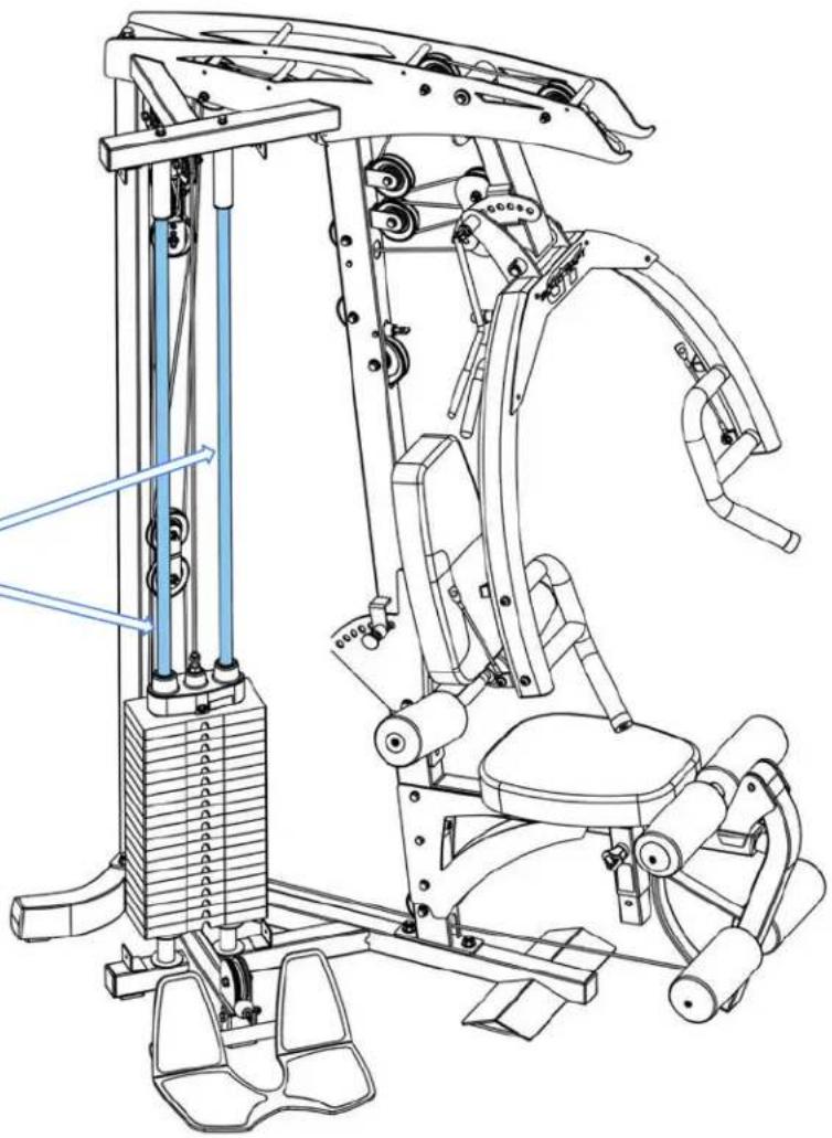
STEP 9a : Lube both Guide Rods (6) with 100% pure Silicone Lube or Teflon PTFE Grease.
ONLY apply a light layer with a clean rag.
Then do a set of reps with low weights to spread the lubricant thoroughly the Guide Rods (6).
Repeat for both right & left sides.

100% COTTON
CLEANING CLOTH

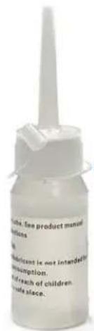
100% PURE SILICONE LUBE
natural_image
Technical line drawing of a stationary exercise machine with vertical supports and mechanical components (no text or labels)TIP: Lubing the Guide Rods (6) is a great practice to do not only at setup, but also during scheduled times for preventive maintenance measures in order to:
- Ensure that the Weight Plates (118) internal bushing glide smoothly for a quiet & long life operation.
- Add protection to the Guide Rods (6) from future potential surface rust in the higher humidity environments.
To purchase additional
Guide Rod lube:
https://www.bodycraft.co
m/product/treadlube5pk/


Product Assembly, GT, STEP 9b w/ Accessory Placement Locations
STEP 9b: Install Weight Stack Shroud Covers & Accessories
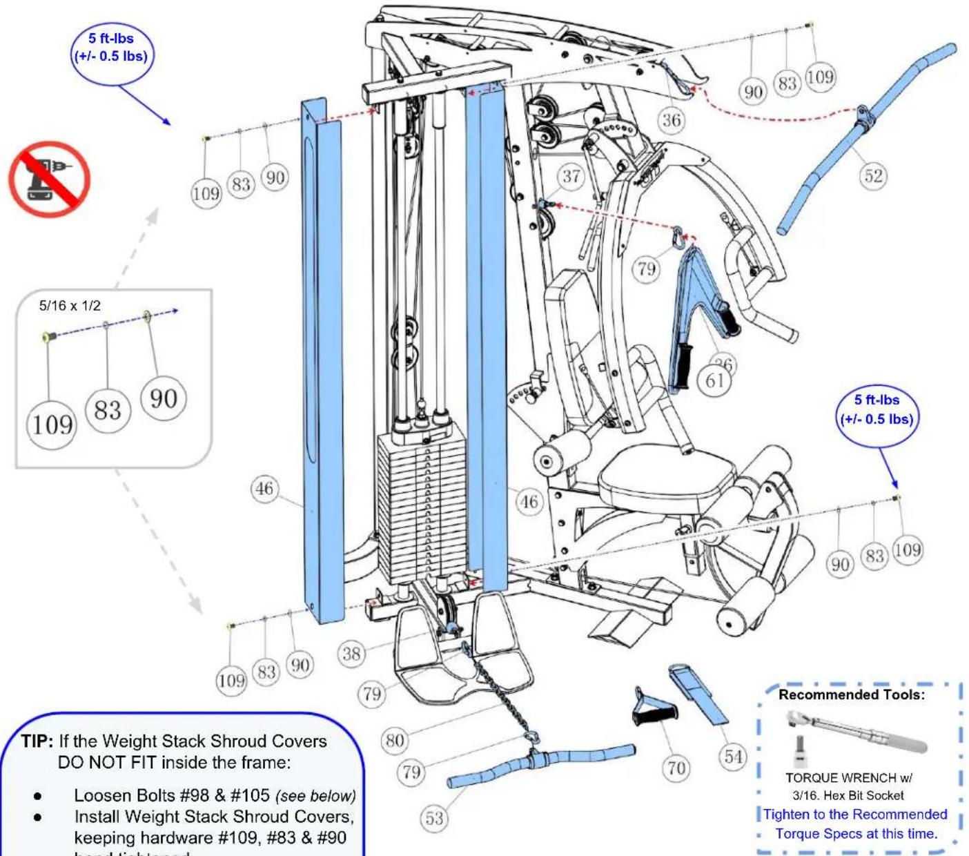
TIP: If the Weight Stack Shroud Covers DO NOT FIT inside the frame:
• Loosen Bolts #98 & #105 (see below)
- Install Weight Stack Shroud Covers, keeping hardware #109, #83 & #90 hand tightened.
• Retorque #98 & #105 Bolts (1st)
• Tighten to the Torque Specs hardware #109, #83 & #90 (2nd)

| Part # | Assembly Hardware QTY | Part # Assembly Parts List QTY | ||
| GT-X-046 Weight Stack Shroud Cover 2 | ||||
| GT-X-083 | Washer, Spring, 5/16" - BLK | 4 | GT-X-052 Accessory, 48" Aluminum Lat Bar 1 | |
| GT-X-053 Accessory, EZ-Curl/Low Row Bar 1 | ||||
| GT-X-090 | Washer, Flat, 5/16" - BLK | 4 | GT-X-054 Accessory, Ankle Cuff (Leg Strap) 1 | |
| GT-X-061 Accessory, Ab Crunch Strap 1 | ||||
| GT-X-109 | Screw, Recessed Flat Head, 5/16" x 1/2" L - BLK | 4 | GT-X-070 Accessory, Single Handle 1 | |
| GT-X-079 Snap Hook 3 | ||||
| GT-X-080 Accessory, Chain, 19" L 1 |
Product Assembly, GT, STEP 9c - Optional Speed Trainer
STEP 9c: Installing the OPTIONAL Speed Trainer

Use the longer Hex Head 5/16 x 3/4 Bolt #404

natural_image
Close-up of a hand holding a blue plastic clip next to a mechanical fixture (no visible text or symbols)
natural_image
Interior view of a vehicle or industrial space with a person climbing a metal handle and blue safety tags visible (no text or symbols)
Recommended Tools:

TORQUE WRENCH
w/ 1/2 SOCKET
Tighten to the Recommended Torque Specs at this time.
5 ft-lbs (+/- 0.5 lbs)

| Part # Assembly Parts List QTY | ||
| S-Trainer-401-ASM | Spring Rope, w/ dual Snap Hooks -Assembly 4 | |
| S-Trainer-402 Hook | Plate, Lower, to Bottom Frame 2 | |
| S-Trainer-403 Hook | Plate, Upper, to Weight Stack 1 | |
| Part # Assembly Hardware QTY | ||
| S-Trainer-404 Bolt, Hex 5/16" x 3/4" L - BLK | 2 | |
| GT-X-083 | Washer, Spring, 5/16" - BLK | 2 |
| GT-X-090 | Washer, Flat, 5/16" - BLK | 2 |
Product Assembly, GT, STEP 10 - Adjust the Cables for Correct Tension
STEP 10: Adjust the Cables for Correct Tension
The Cables should be tightened to the point just before the Top Plate lifts off the stack. See below for Major Adjustments or Fine Adjustment for correct cable adjustments.
Good Rule of Thumb: Cable above weight stack should have less than 1/2 inch of play in the cable.
Major Adjustment - 1" or more
- Double Pulley Block #17
- Realign pulley into the next hole.

natural_image
Technical line drawing of a mechanical device with multiple arms and levers (no text or symbols)Check Selector Rod Pin freely slides into each weight plate front hole with the Top Plate resting on 1st Weight Plate.
Once adjusted correctly, retighten all jam nuts & pulley hardware.
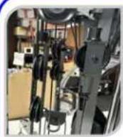
BODYCRAFT
Watch Assembly Video
GT STEP 10
Adjusting the Cables

Fine Adjustment - 1/2" or less
- Start of Cable #36 at Top Plate
- Then Adjustable Stoppers #41-ASM

Recommended Tools:
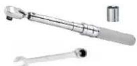
TORQUE WRENCH w/ 9/16 SOCKET & 9/16 WRENCH

ADJUSTABLE WRENCHES
After all adjustment are done, tighten to the Recommended Torque Specs at this time.
Recommended Conditions & Items for Installation of the Weight Stack Stickers

MINIMUM 65 DEGREES & LOW

natural_image
Two white rectangular sheets of paper, overlapping slightly (no text or symbols visible)CLEAN COTTON CLOTH
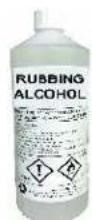
RUBBING ALCOHOL
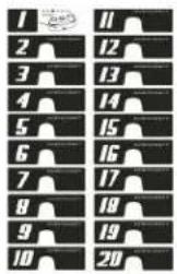
WEIGHT STACK STICKERS-SHEET (81)
IMPORTANT: Before installing the weight stack stickers, it is important to let the weight plates acclimate to room temperature.
a. Clean Top Plate Assembly (55-ASM) & Weight Plates (118) front surface with Rubbing Alcohol and a Clean Cotton Cloth. Then wipe dry with another clean cloth or allow to completely air dry.
b. Starting from the Top Plate Assembly (55-ASM), install Weight Stack Stickers (81) for first sticker #1.



c. Continue installing Weight Stack Stickers (81) one at a time starting from the first Weight Plate (118) using sticker #2. Apply all corresponding stickers per each weight plate.

d. Once the label is carefully aligned with each weight plate (118), press each numbered sticker gently onto the correct weight plate. Only rub each sticker and not the surrounding area. e. Perform the same procedure from a, b, c & d to opposite side. f. DO NOT "TEST" the sticker by pulling on it at any time after installed on weight stack plates.
NOTE: Allow the adhesive to cure for a minimum of 24 hrs. Room humidity and temperature will affect the cure time.
Product Assembly, GT, STEP 12 - Final Assembly Clean up, Lube & Polish

STEP 12a: Remove all Assembly Stickers, i.e. Part Numbers & Right / Left Circles
- Easy to remove with fingernail or plastic scraper
-
If adhesive residue is on frame:
-
Use rubbing alcohol
- Then mild cleaning solution
○ Finishing with a dry 100% cotton cleaning cloth

STEP 12b: Frame Clean Up
- Wipe down frame with mild cleaning solution
- Dry frame with 100% cotton cleaning cloth
• Good practice to do before first use and yearly:
○ Lightly apply an automotive grade cleaner wax
- Then follow up by wiping excesses off with 100% cotton cleaning cloth
• DO NOT USE ABRASIVE CLEANING SCRUBBING PADS
• DO NOT USE AMMONIA OR CITRIC CLEANERS
• DO NOT USE ANY FORM OF PAINT THINNERS

TIP ON FRAME ONLY: For extra protection from fingerprints, sweat stains or just plain dirt, apply an automotive grade cleaner wax if desired. Also makes future cleaning easier.
(Do Not Use on the Upholstery)
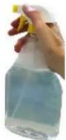
MILD CLEANING SOLUTION

natural_image
Two white sheets of folded paper, no text or symbols visible100% COTTON CLEANING CLOTHS

natural_image
Close-up of a slice of black sugar with white cream being poured into it, no text or symbols visibleProduct Disassembly & Relocation, GT/GTX

natural_image
Top-down view of a mechanical tool set including tools, pliers, and a digital device on a textured surface (no visible text or symbols)BODYCRAFT
Watch Video
GT/GTX
Disassembly & Relocation


natural_image
Exterior view of a modern rehabilitation machine with adjustable arms and legs, placed on a wooden floor (no visible text or symbols)Product Assembly, Routine Schedule, GT
| ROUTINE SCHEDULE | LIGHT COMMERCIAL | HOME |
| Clean: Upholstery. | DAILY | 1 - 2 WEEKS |
| Inspect: Cables or Belts and their tension. | DAILY | 1 - 2 WEEKS |
| Inspect: Links, Pull Pins, Snap Locks, Swivels, and Weight Stack Pins. | DAILY | 1 - 2 WEEKS |
| Inspect: Accessory Bars and Handles. | WEEKLY | 3 - 6 MONTHS |
| Inspect: All Label and Weight Stack Stickers. | WEEKLY | 3 - 6 MONTHS |
| Inspect: All Nuts and Bolts, tighten if needed. | WEEKLY | 3 - 6 MONTHS |
| Inspect: Anti-Skid Surface. | WEEKLY | 3 - 6 MONTHS |
| Clean & Lubricate: Guide Rods with 100% Silicone or a Teflon based lubricant with Super Lube (a PTFE grease). | MONTHLY | 3 - 6 MONTHS |
| Lubricate: Seat Sleeves, Bushings, Linear Bearing. | MONTHLY | 3 - 6 MONTHS |
| Clean and Wax: All Glossy Finishes. | 6 MONTHS | YEARLY |
| Repack with Grease: Linear Bearings. | 6 MONTHS | YEARLY |
| Replace: Cables, Belts and Connecting Parts when showing signs of wear. | YEARLY | 2 - 4 YEARS |
General Inspection and Cleaning
The Frame should be wiped down with a damp cloth and dried on a daily basis. The powder coat finish should be polished with a good car wax on a yearly basis. For Vinyl Upholstery use Lanolin hand cleaner to dissolve sweat and lubricate the vinyl, maintaining its natural flexibility. DO NOT use cleaners such as Lysol or Windex as they will dry out and crack the vinyl. Sweat is corrosive and when left on the frame and components will eventually cause corrosion or rust. When performing these cleaning sessions, it is the perfect time to inspect the equipment and note any problems for the maintenance personnel to correct.
- Check equipment to ensure it is operating properly.
- Check the cables for loose fittings or frayed cable(s) and to ensure seating is proper on the pulleys and cams (if equipped).
- Make sure that the proper weight stack selector pin is with each machine and that the pin functions properly.
- If something appears loose, be sure to have it tightened immediately.
- If a piece of equipment appears damaged or not operating properly, place the piece out-of-service immediately.
Cable Inspection
It is important to inspect the cables frequently, replace any worn out cables to prevent a sudden failure that can result in an injury. Cables are moving parts, meaning cable-wear will occur regardless of the type or size used.
-
Inspect cable ends and perform any cable tension adjustments, loosen the jam nut and thread the cable bolt in or out to give cable the proper tension. Re-tightened all jam nuts when adjustment is complete and make sure the cable bolt is threaded 1/3 into the socket of the selector stem in the top plate.
-
Check the cables as they pass over all pulley wheels. Visually inspect the cables and pulleys. A cable that is wearing will exhibit a ballooned surface that passes over the pulleys. This is an early warning sign to replace the cable(s).
Lubrication
Bearing and linear bearing systems have advanced over the years, but they must be maintained on a regular basis if you expect them to last and perform efficiently. BODY-CRAFT uses only the highest quality bearings and linear motion components that are virtually trouble-free but they require the regular preventive maintenance to ensure long-lasting performance.
-
Bronze bushings: Recommend on a yearly basis to spray a Teflon-base lubricant (silicone-free) directly onto the shaft as it passes through these bushings. Spray a small amount onto the shaft and rotate it through its complete movement and wipe off any excess.
-
Weight stack guide rods: Use Silicone Spray lubricant and this time spray onto a rag and wipe the guide rods down with this rag on a weekly basis. DO NOT use WD-40 or other lubricants as they attract dirt and will create a mess between the weight plates and bushings.
-
Sealed bearings pivot points: As the name implies, they are protected from the outside environment and require no lubrication. During the machine wipe down, wipe the external bearing surfaces with the damp rag and dry to prevent the build up of dust and sweat.
-
Linear bearing systems (if equipped): These are precision, high load components that require regular maintenance. Dirt and corrosion are the major culprits in linear bearing failure. The hardened shafts must be wiped down monthly and lubricated with a light layer of Teflon grease. We recommend a Teflon-based (silicone-free) gel/grease for this purpose. Lack of care and maintenance will result in corrosion of the linear shaft causing the bearings to become clogged and jammed.
If you perform the maintenance procedures, you will increase the life of the machine and ultimately lower your maintenance costs with fewer replaced components and downtime.

BODYCRAFT 7699 GREEN MEADOWS DR. LEWIS CENTER, OHIO 43035

800.990.5556 SERVICE@BODYCRAFT.COM WWW.BODYCRAFT.COM
Product Assembly, Strength Cable Wear Indicators, GT

Casing can crack or fracture under strains during use. Any crack in the casing merits cable replacement even if no wire rope is exposed.
STOP USING THE MACHINE: This cable needs to be replaced as soon as possible.
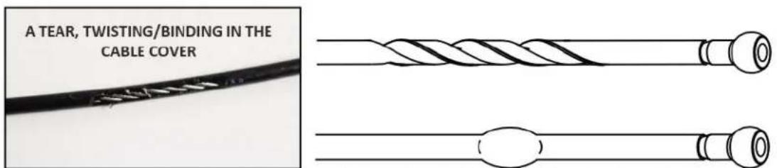
Inspect casing to ensure wire rope is not tearing, twisting, or binding within and coil causing bulge to appear. Cable should retain same outside diameter throughout.
STOP USING THE MACHINE: This cable needs to be replaced as soon as possible.

Any exposed wire rope protruding through the casing or at either end, has lost its structural integrity. Section of cable is compressed and will not retain its shape (outside diameter).
STOP USING THE MACHINE: This cable needs to be replaced immediately.

Cable has a kink and prohibits cable from lying straight. Wire rope may be unraveling beneath the casing, causing a compromise of its structural integrity.
STOP USING THE MACHINE: This cable needs to be replaced immediately.

Watch for component end of cable to pull away from cable assembly and look for exposed wire rope.
STOP USING THE MACHINE: This cable needs to be replaced immediately.
Detailed Parts, Exploded View, GT 1 of 3

NOTE: Parts are not to scale
Detailed Parts, Exploded View, GT 2 of 3

Detailed Parts, Exploded View, GT 3 of 3
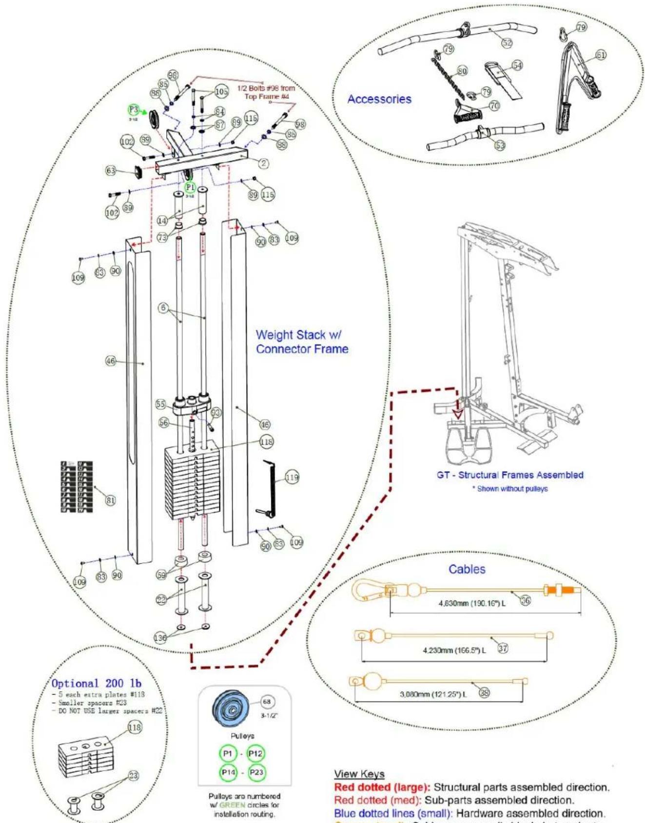
NOTE: Parts are not to scale
View Keys
Red dotted (large): Structural parts assembled direction. Red dotted (med): Sub-parts assembled direction. Blue dotted lines (small): Hardware assembled direction. Orange (med): Cables are normally black, but easier to see in color.
Detailed Parts List - GT 1 of 4
| Part # Detailed Parts list QTY | ||
| GT-X-001 Frame | Bottom 1 | |
| GT-X-002 Frame | Connector, Top 1 | |
| GT-X-003 Frame | Front, Upright 1 | |
| GT-X-004 Frame | Top 1 | |
| GT-X-005 Frame | Rear, Upright 1 | |
| GT-X-006 | Guide Rod, 1" OD x 72-1/2" L, 3/8" nuts inserted & welded both ends 2 | |
| GT-X-007 Press Arm 1 | ||
| GT-X-008 Trim Panel, Blue, for Top of Press Arm 1 | ||
| GT-X-009-ASM Handlebar, Left w/ Dipped Rubber Grip - Assembly 1 | ||
| GT-X-010-ASM Handlebar, Right w/ Dipped Rubber Grip - Assembly | 1 | |
| GT-X-011 | Adjusting Frame for Seat Pad | 1 |
| GT-X-012 Support Frame for Seat Pad | 1 | |
| GT-X-013 Leg Extension Arm, w/ Dual Holes for Different User Sizes | 1 | |
| GT-X-014 Limit Tube 2 | ||
| GT-X-015 Adjusting Frame for Back Pad | 1 | |
| GT-X-016 Connecting Frame for Press Arm | 1 | |
| GT-X-017 Pulley Block, Double, Closed Flat End, Adjustable w/ 13 each | 1 | |
| GT-X-018 Foot Plate for Low Row | 1 | |
| GT-X-019 | Pulley Block, Single Closed Flat End, w/ Cable End Threaded Shaft | 1 |
| GT-X-020 Frame | Knee Hold Down | 1 |
| GT-X-021 | Connect Cable from Press Arm to Functional Cable Arms, 200mm (7.87") L | 2 |
| GT-X-022 Stack Spacer, Tall, 7" for 150lb weight stack | 2 | |
| GT-X-023 Stack Spacer, Short, 3" for Optional 200lb weight stack | 2 | |
| GT-X-024 Metal Hinge to Seat Back Pad | 2 | |
| GT-X-025 Remote Handle for Press Arm Adjustments | 1 | |
| GT-X-026 | Axle, for Press Arm, Lower, 20mm OD (solid w/ no flat notch) x 186mm L | 1 |
| GT-X-027 | Axle, for Leg Extension Arm, w/ one side flat notch, 12.7mm OD x 5/16" threaded ID x 67.5mm L | 1 |
| GT-X-028 | Axle, for Press Arm, Upper, 20mm OD x 3/8" threaded ID x 114mm L | 1 |
| GT-X-029 Pad, Seat | 1 | |
| GT-X-030 Pad, Back with BodyCraft Logo | 1 | |
| GT-X-033 Non Slip Sticker, Lower Left for Foot Plate | 1 | |
| GT-X-034 Nonslip Sticker, Lower Right for Foot Plate | 1 | |
| GT-X-035 Nonslip Sticker, Upper for Foot Plate | 2 | |
(20)

(21)

(22)

(23)

(24)

(26)


(28)

(29)

(25)

natural_image
Technical line drawing of a mechanical clamp or bracket assembly (no text or symbols)(1)

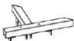
(2)

natural_image
Technical line drawing of a vertical metal frame with mounting flanges (no text or symbols)(3)

(5)

(6)

(8)

(9)
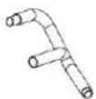
(10)

natural_image
Technical line drawing of a curved mechanical component with mounting holes and a separate triangular bracket (no text or symbols)
(14)

(11)

(13)

(12)
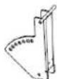
(15)

(16)

(17)
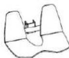
(18)

(19)

(30)

(33)

(34)

(35)
NOTE: Parts are not to scale
Detailed Parts List - GT 2 of 4
| Part # Detailed Parts list QTY | ||
| GT-X-036 Cable, Top, 4,830mm (190.16") L 1 | ||
| GT-X-037 Cable, Ab Crunch, 4,230mm (166.5") L 1 | ||
| GT-X-038 Cable, Lower, 3,080mm (121.25") L 1 | ||
| GT-X-039 End Cap, Aluminum - BLUE 2 | ||
| GT-X-040 | Threaded Rod, between Top Connector Frame & Single Block Pulley (Not used with FCA) 1 | |
| GT-X-041 Adjustable Stopper, for the Adjustable Pulley Block 1 | ||
| GT-X-042 Pull Pin Rod | 1 | |
| GT-X-043 Spacer Sleeve, for Dual Pullies on Upper Frame | 1 | |
| GT-X-044 Bearings, Industrial Ball, φ12.7 x φ28.5 x φ32 x δ11 (1/2" ID) | 2 | |
| GT-X-045 | Handle Cover, Fixed to 007 Press Arm, Neopreme, φ15mm x φ21mm x 115mm - BLK" | 1 |
| GT-X-046 Weight Stack Shroud Cover 2 | ||
| GT-X-047 Pop-Pin, Aluminum , 55mm L (46mm) - BLUE | 1 | |
| GT-X-048 Pull-Pin Locking Knob, Aluminum - BLUE | 1 | |
| GT-X-049 | Handle Cover, 025 Adjustable Remote Handle for Press Arm, Neoprene, φ12mm x φ16mm x 105mm - BLUE | 1 |
| GT-X-050 | Support Tube for 051 Rollers, Stainless Steel, 5/16" nuts inserted & welded on both ends | 2 |
| GT-X-051 Roller, Upholstered Foam | 6 | |
| GT-X-052 Accessory, 48" Aluminum Lat Bar | 1 | |
| GT-X-053 Accessory, EZ-Curl/Low Row Bar | 1 | |
| GT-X-054 Accessory, Ankle Cuff (Leg Strap) | 1 | |
| GT-X-055 Top Plate | 1 | |
| GT-X-056 Selector Rod, 19 Holes | 1 | |
| GT-X-057 Rubber Cover for Hooks, on Rear Upright Frame | 2 | |
| GT-X-058 Compression Spring | 1 | |
| GT-X-059 Rubber Cushion for Weight Stack | 2 | |
| GT-X-060 Stopper for Connection Arm, Leg Extension Arm and Back Pad | 3 | |
| GT-X-061 Accessory, Ab Crunch Strap | 1 | |
| GT-X-062 Plug, Round, Φ32 | 2 | |
| GT-X-063 Square Plug 50x50 | 4 | |
| GT-X-064 Plug, Rectangular Plug, 50mm x 25mm | 2 | |
| GT-X-065 Plug, Rectangular, 75mm x 50mm | 2 | |
| GT-X-066 End Cap for Upholstered Roller, Large Hole, Plastic - BLK | 6 | |
| GT-X-067 End Cap for Upholstered Roller, Small Hole, Plastic - BLK | 6 | |
| GT-X-068 Pulley, 90mm (3-1/2") x δ26mm ID | 22 | |
| GT-X-069 Pulley, 114mm (4-1/2") x δ26mm ID | 1 | |
| GT-X-070 Accessory, Single Handle | 1 | |
| GT-X-071 Pulley Block, Double | 1 | |
| GT-X-072 Bearing, w/ Deep Groove Ball,6004-2Z (C0) | 2 | |
| GT-X-073 Bushing, Flange, MFM-2532-20 | 2 | |

| Part # Detailed Parts list QTY | ||
| GT-X-074 Bushing, Flange, MFM-1216-10 2 | ||
| GT-X-075 Bushing, Brass, 1/2" ID 2 | ||
| GT-X-076 | Bushing, Plastic, for Pulley to Frame, 3/8" ID 8 | |
| GT-X-077 | Bushing, Steel, for Upper Pulleys & Press Arm, 20mm ID 4 | |
NOTE: Parts are not to scale
Detailed Parts List - GT 3 of 4
| Part # | Detailed Parts list | QTY |
| GT-X-077 Bushing, Steel, for Upper Pulleys & Press Arm, 20mm ID 4 | ||
| GT-X-078 Connecting Chain Link 1 | ||
| GT-X-079 Snap Hook 3 | ||
| GT-X-080 Accessory, Chain, 19" L 1 | ||
| GT-X-081 Sticker, Weight Stack 1 - 20 1 | ||
| GT-X-082 Washer, Spring, φ5mm - Stainless Steel 4 | ||
| GT-X-083 Washer, Spring, 5/16" - BLK 8 | ||
| GT-X-084 Washer, Spring, 3/8" - BLK 16 | ||
| GT-X-085 Washer, Spring, 1/2" - BLK 4 | ||
| GT-X-086 Washer, Flat, Large, φ8mm - BLK 6 | ||
| GT-X-087 Washer, Flat, Large, φ10mm - BLK 4 | ||
| GT-X-088 Washer, Flat, 1/2" - BLK 12 | ||
| GT-X-089 Washer, Flat, 3/8" - BLK 70 | ||
| GT-X-090 Washer, Flat, 5/16" - BLK 11 | ||
| GT-X-091 Bolt Cap for Pull Pin Rod, Perforated, 3/4" - BLK 1 | ||
| GT-X-092 Bolt, Shoulder, Φ12mm x 25mm x M8 - Stainless Steel 1 | ||
| GT-X-093 Bolt, Recessed Round Head, 7/16" x 1-3/4" L - BLK 1 | ||
| GT-X-094 Bolt, Recessed Round Head, 5/16" x 1-1/4" L - BLK 6 | ||
| GT-X-095 Screw, Inner Hex, 5/16" x 1/4" L - BLK 3 | ||
| GT-X-096 Screw, Inner Hex, 5/16" x 1/2" L - BLK 1 | ||
| GT-X-097 Bolt, Hex Head, 1/2" x 3-5/8" L - BLK 1 | ||
| GT-X-098 Bolt, Hex Head, 1/2" x 5-1/4" L - BLK 2 | ||
| GT-X-099 Bolt, Hex Head, 1/2" x 3" L - BLK 2 | ||
| GT-X-100 Bolt, Hex Head, 5/16" x 3/4" L - BLK 2 | ||
| GT-X-101 Bolt, Hex Head, 3/8" x 1" L - BLK 6 | ||
| GT-X-102 Bolt, Hex Head, 3/8" x 2" L - BLK 16 | ||
| GT-X-103 Bolt, Hex Head, 3/8" x 2-7/8" L - BLK 4 | ||
| GT-X-104 Bolt, Hex Head, 3/8" x 3" L - BLK 5 | ||
| GT-X-105 Bolt, Hex Head, 3/8" x 3-1/4" L - BLK 2 | ||
| GT-X-106 Bolt, Hex Head, 3/8" x 3-3/4" L - BLK 2 | ||
| GT-X-107 Bolt, Hex Head, 3/8" x 5" L - BLK 4 | ||
| GT-X-108 Screw, Recessed Flat Head, 5/16" x 3/4" L - BLK 2 | ||
| GT-X-109 Screw, Recessed Flat Head, 5/16" x 1/2" L - BLK 4 | ||
| GT-X-110 | Screw, Recessed Flat Head, 3/8" x 1-1/4" L - BLK 4 | |
| GT-X-111 | Screw, Recessed Flat Head, 3/8" x 1-1/8" L - BLK 2 | |
| GT-X-112 | Screw, Recessed Flat Head, 5/16" x 1" L - BLK 3 | |
| GT-X-113 | Screw, Recessed Flat Head, M5 x 10mm L - Stainless Steel 4 | |
| GT-X-114 | Screw, Recessed Countersunk Head, 5/16" x 1" L - BLK 2 | |
| GT-X-115 | Nut, Nylon Lock, 3/8" - BLK 29 | |
| GT-X-116 | Nut, Nylon Lock, 1/2" - BLK 7 | |
| GT-X-117 | Nut, 1/2" - BLK 2 | |
| GT-X-118 | Weight Plate, 10lbs (4.5kg) ***(19 plates with 200lb upgrade)*** 14 | |
| GT-X-119 | Selector Pin w/ Lanyard, Aluminum - BLUE 1 | |


(88)

Detailed Parts List - GT 4 of 4
| Part # | Detailed Parts list | QTY |
| GT-X-120 Silicone | Lube Bottle, for Guide Rods 1 | |
| GT-X-121 Poster | - Exercise Guide for GT Strength Training System 1 | |
| GT-X-122b Warning | Label - Master Rules and Precautions - v1.6v 1 | |
| GT-X-123b Warning | Label - Pinch Point, Vertical- v1.6 1 | |
| GT-X-124b Warning | Label - Pinch Point, Horizontal - v1.6 2 | |
| GT-X-125b Warning | Label - Be Aware of Moving Parts - v1.6 1 | |
| GT-X-126b | Warning Label - Do Not at Any Time Lean Against Frame - v1.6 1 | |
| GT-X-127b Warning | Label - Pull-Pin Locking Knob - v1.6 1 | |
| GT-X-128b Warning | Label - California Proposition 65 1 | |
| GT-X-129b Label | - Maintenance Schedule - v1.6 1 | |
| GT-X-130b Label | - Serial Number 1 | |
| GT-X-131b Label | - Gear Adjustment for Press Arm 1 | |
| GT-X-132b Label | - Gear Adjustment for Back Pad 1 | |
| GT-X-133b Warning | Label - Do Not Hang on Bar - v1.6 1 | |
| GT-X-134 Wrench | Hex 3/16" 1 | |
| GT-X-135 Wrench | Hex 3/8" 1 | |
| GT-X-136 | Washer, Spacer, Large, for bottom of Guide Rods, 50mm OD x 11mm ID x 5mm Thick - BLK | 2 |
| GT-X-137 Wrench | Hex, 5/32" 1 | |
| GT-X-138 Wrench | Hex, 1/4" 1 |


(121)
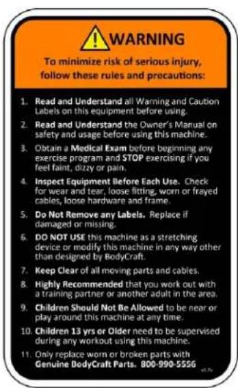
(122b)

(136)

(123b)

(124b)

(126b)
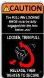
(127b)

(132)

(125b)

(128b)

(133b)
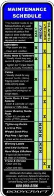
(129b)

(130b)
NOTE: Parts are not to scale
Required Information BEFORE Initiating a Service Case
The following information is needed to help expedite troubleshooting and to ensure the correct part(s) are sent if needed for a repair:
1) What product / model # do you have?
2) Unit serial number?
3) Installed by a dealer or direct sale?
4) Date of installation?
5) Date of service issue?
8) What part(s) are being requested?
6) Complaint or problem, including any Error Codes?
7) Cardio &/or Connect 22 tablet, has the software been updated?
9) Any picture or video will help with troubleshooting or exact part(s) needed.
Product Warranty - Strength Equipment (Home Use ONLY)
VALID FOR USA AND CANADA ONLY
(Please consult with your local distributor for warranty info specific to your region).
BODYCRAFT warrants its products to be free of defects in materials and workmanship for the time stated below to the original purchaser.
Register your product within 30 days of purchase at www.bodycraft.com or call 800-990-5556
This warranty is valid only in accordance with the following conditions:
The warranty begins on the original purchase date at retail and ends when the original owner disposes of it, either through sale, gift, or otherwise. This warranty is not transferable and is only valid to the original purchaser.
This warranty is available only for purchases made within and the original purchaser currently residing in the USA and Canada. Please consult with your local distributor for warranty information specific to your region. The product must have been registered within 30 days of the original purchase date or supply proof of purchase to validate warranty (original sales invoice).
This warranty does not extend to any losses or damages due to accident, misuse, abuse, neglect, negligence, unauthorized modification or alteration, use beyond rated capacity, unsuitable power sources or environmental conditions, water, tampering, cosmetic damages, or improper installation, handling, repair, maintenance, or application, or lack of proper maintenance.
If the item exhibits such a defect, BODYCRAFT will, at its option, repair or replace it without cost for parts. Shipping and handling charges may apply. (BODYCRAFT may require return of the part(s) or photographic evidence of the damaged part(s) prior to replacement.) Serial number is required.
Parts repaired or replaced will be warranted for the remainder of the original warranty period only.
Warranty for Strength Equipment: Residential Use
Frame: Lifetime
Moving Parts: 10 years
(Weight plates, pulleys, bearings, & bushings)
Cables/Belts, Upholstery & Accessories: 10 years
(Finish/Coatings & all other parts not listed above)
Labor: 90 days
This warranty excludes the following:
- The warranty does not cover normal maintenance or labor charges unless labor terms are listed above.
- Normal cosmetic wear on parts such as paint, seat coverings, foot rails, labels and logos.
- Any accessories not included in the original packaging.
- Warranty does not cover normal wear and tear.
* This warranty is in lieu of all warranties, expressed or implied, and/or all other obligations or liabilities on our part, and we neither assume nor authorize any person to assume for us any other obligation or liability in connection with the sale of your BODYCRAFT product. Under no circumstances shall we be liable by virtue of this warranty or otherwise for damage to any person or property whatsoever for any special, indirect, incidental, secondary or consequential damage of any nature whatsoever arising out of the use or inability to use the BODYCRAFT product.
Register your product's warranty at www.bodycraft.com/product-registration.html
Warranty Registration - Strength
Thank you for purchasing a BODYCRAFT product. To validate the product warranty the fast and easy way, please go on-line now to https://www.bodycraft.com/product-registration.html and register your product. The information you provide will never be distributed to any other individuals or agencies for any purpose. If you prefer to mail your warranty card, have the owner of the product complete the information below and return it to BODYCRAFT within 30 days from the date of equipment installation.
Please Note: Failure to register this product may result in no servicing or authorization of parts to be shipped.
To mail your warranty information, please fill in the information below and mail to: Service Dept., BODYCRAFT, 7699 Green Meadows Dr. Lewis Center, Ohio 43035 (or save postage and register online at https://www.bodycraft.com/product-registration.html)
WARRANTY REGISTRATION
PLEASE PROVIDE SERIAL NUMBER(S) BELOW, REQUIRED FOR WARRANTY REGISTRATION:
BASE UNIT SERIAL NUMBER:
OPTIONS SERIAL NUMBER(S):
Model Type ____
Date of Purchase ____
Your Company Name
Contact First Name
Contact Last Name
Address
City State ZP
Email Address____Website____
Phone____Fax____
- Where did you first learn about BODYCRAFT?
a. Dealer b. Website
c. Advertisement d. Referral
____ e. Current Customer ____ f. Other ____
- Why did you purchase a BODYCRAFT product?
a. Design/Appearance b. Dealer Suggestion
c. Price/Value d. Quality Construction
e. Performance f. BODYCRAFT Reputation
g. Other:
- Please indicate your type of facility:
a. Apartment/Condo b. Corporate Fitness Center
c. Municipality d. Health Club/Gym/Spa
e. Hotel/Resort f. Military Base
g. Student Rec Center h. Home
- What other types of equipment does your company or home currently own?
a. Treadmill Brand
b. Elliptical Brand
c. Bike/Indoor Cycle Brand
d. Free Weights/Gym Brand
- How many people use your facility on a daily basis?
a. <25 b. 25-75
c. 76-150 _d. 150+
- Do you plan to purchase more fitness equipment in the next 6-12 months?
Yes ____ No
- If you answered "yes" to question 6, what type do you plan to purchase?
a. Treadmill b. Elliptical
c. Bike/Indoor Cycle d. Free Weights
e. Gym f. Other
- Would you recommend BODYCRAFT to other club or home owners?
____Yes ____No
- You are a valued BODYCRAFT customer and your suggestions allow us to continually improve your experience. Is there anything else you would like us to know? Please explain:

natural_image
Simple black-and-white icon of a telephone handset inside a circle (no text or symbols)800.990.5556
SERVICE@BODYCRAFT.COM
WWW.BODYCRAFT.COM
BODYCRAFT
7699 GREEN MEADOWS DR.
LEWIS CENTER, OHIO 43035
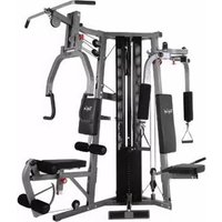
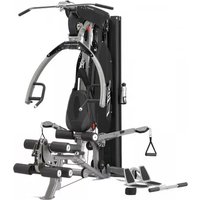
- GT Strength Training System
- Owner's Manual
- Congratulations and Welcome to the BODYCRAFT Family
- Table of Contents - GT 1 of 2
- Product Safety Information
- Page
- Product Overview
- Product Assembly - How to Assemble the GT
- Table of Contents - GT 2 of 2
- Maintenance & Repairs
- Warranty
- Product Safety - Functional Trainers, Duals & Multi-Gyms
- Important Notes, Recommended Tools & Cleaners, GT
- Important Notes and Tips:
- THE FOLLOWING TOOLS ARE RECOMMENDED FOR ASSEMBLY:
- THE FOLLOWING IS RECOMMENDED FOR CLEANING:
- Machine Options, GT
- Machine Dimensions & Room Layouts, GT
- GT Overall Dimensions
- Assembly Parts - Hardware, GT 3 of 3
- Large Box 1 of 2
- Medium Box 2 of 2
- Small Boxes
- PREASSEMBLY TIP #1 - "Stage Right".
- PREASSEMBLY TIP #2 – Unpackaging & organizing.
- PREASSEMBLY TIP #3 - Keep hardware loose until asked to tighten.
- Please Hand Tighten All Nuts & Bolts Until STEP 2a
- CAUTION
- View Keys
- STEP 2a: "Torque Time" on Main Frame Nuts & Bolts from STEP 1a - 1d
- Tighten to torque specs to ensure the bolts and nuts do the following:
- DECISION POINT
- GT - STEP 2c
- AND
- Product Assembly, GT, STEP 3a
- GT - STEP 3c
- Product Assembly, GT, STEP 3d
- Product Assembly, GT, STEP 4c
- Weight Stack
- STEP 5d: Lightly Lube Guide Rods
- STEP 5e: Install Stack Spacers, Rubber Cushions, Weight Plates, & Top Plate w/ Selector Rod
- Product Assembly, GT, STEP STEP 6a & Optional SpeedTrainer
- OPTIONAL Speed Trainer
- Please Hand Tighten All Nuts & Bolts Until STEP 6n
- Product Assembly, GT, STEP 6l - 6m
- Product Assembly, GT, STEP 6n - "Torque Time"
- STEP 6n: "Torque Time"
- Product Assembly, GT, STEP 7 (Ab Cable #37) OVERVIEW
- OVERVIEW IMAGE for STEP 7 (w/o Options) ... Start Assembly on page 44
- Product Assembly, GT-FCA (GTX), STEP 2 (Ab Crunch Cable #310) - OVERVIEW
- OVERVIEW IMAGE for STEP 7 (w/ GT-FCA Options) ... Start Assembly on page 44
- Please Hand Tighten All Nuts & Bolts Until STEP 7h
- STEP 7c: Install Pulley P15
- TOP VIEW
- Product Assembly, GT, STEP 7h - "Torque Time"
- STEP 7h: "Torque Time"
- Product Assembly, GT, STEP 8 (Lower Cable #38) OVERVIEW
- OVERVIEW IMAGE for STEP 8 (RIGHT SIDE) ... Start Assembly on page 49
- Please Hand Tighten All Nuts & Bolts Until STEP 8g
- Product Assembly, GT, STEP 8f & 8g - "Torque Time"
- STEP 8g: "Torque Time"
- STEP 9a : Lube both Guide Rods (6) with 100% pure Silicone Lube or Teflon PTFE Grease.
- Product Assembly, GT, STEP 9b w/ Accessory Placement Locations
- Product Assembly, GT, STEP 9c - Optional Speed Trainer
- Product Assembly, GT, STEP 10 - Adjust the Cables for Correct Tension
- STEP 10: Adjust the Cables for Correct Tension
- Major Adjustment - 1" or more
- Fine Adjustment - 1/2" or less
- Recommended Conditions & Items for Installation of the Weight Stack Stickers
- Product Assembly, GT, STEP 12 - Final Assembly Clean up, Lube & Polish
- STEP 12a: Remove all Assembly Stickers, i.e. Part Numbers & Right / Left Circles
- STEP 12b: Frame Clean Up
- Product Disassembly & Relocation, GT/GTX
- General Inspection and Cleaning
- Cable Inspection
- Lubrication
- Product Assembly, Strength Cable Wear Indicators, GT
- Detailed Parts List - GT 1 of 4
- Detailed Parts List - GT 2 of 4
- Detailed Parts List - GT 4 of 4
- Required Information BEFORE Initiating a Service Case
- Product Warranty - Strength Equipment (Home Use ONLY)
- VALID FOR USA AND CANADA ONLY
- This warranty is valid only in accordance with the following conditions:
- Warranty for Strength Equipment: Residential Use
- This warranty excludes the following:
- Warranty Registration - Strength
- WARRANTY REGISTRATION
Brand : BodyCraft
Model : GT/X Functional Cable Arm
Category : Fitness Equipment