
CT-SDCF-PRO - Flat Panel Mount Proaim - Free user manual and instructions
Find the device manual for free CT-SDCF-PRO Proaim in PDF.


| Product Type | Flat Panel Mount |
| Compatible Screen Sizes | 26" to 55" |
| VESA Compatibility | 100x100mm to 400x400mm |
| Maximum Weight Capacity | 50 kg (110 lbs) |
| Material | Heavy-duty cold-rolled steel |
| Finish | Black powder coating |
| Tilt Range | 0° to -15° (forward tilt) |
| Swivel Range | ±30° |
| Level Adjustment | ±3° |
| Distance from Wall | 2.0 inches (51 mm) |
| Installation Pattern | Universal VESA mounting holes |
| Included Hardware | M4, M5, M6, M8 screws, spacers, wall anchors |
| Wall Plate Dimensions | 26.5 x 4.5 inches (673 x 114 mm) |
| Net Weight | 5.2 lbs (2.36 kg) |
| Warranty | 1 year limited |
| Certification | UL listed, TUV approved |
| Usage | Indoor, dry location |
| Cable Management | Integrated cable clips |
| Security Lock | Compatible with Kensington lock (not included) |
| Panel Thickness Support | Up to 2 inches (51 mm) |
Frequently Asked Questions - CT-SDCF-PRO Proaim
User questions about CT-SDCF-PRO Proaim
0 question about this device. Answer the ones you know or ask your own.
Ask a new question about this device
Download the instructions for your Flat Panel Mount in PDF format for free! Find your manual CT-SDCF-PRO - Proaim and take your electronic device back in hand. On this page are published all the documents necessary for the use of your device. CT-SDCF-PRO by Proaim.
USER MANUAL CT-SDCF-PRO Proaim
Soundchief Pro Cart (CT-SDCF-PRO)
Assembly Manual

natural_image
Black wheeled cart with two wheels and overhead support (no text or symbols visible)What's In The Box
Please inspect the contents of your shipped package to ensure you have received everything that are listed below.

natural_image
Empty black metal frame with bolt holes and mounting feet (no text or symbols)1 x Main section

natural_image
Pure diagram of a computer monitor layout without any text, numbers, or symbols
natural_image
Pure electrical circuit lines without any symbols2 x Top side panel

natural_image
Black rectangular electronic component with a rectangular cutout and mounting holes (no text or symbols visible)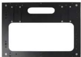
natural_image
Black rectangular object with rounded corners and a small rectangular cutout on top, no visible text or symbols.2 x Bottom side panel
All rights reserved.
No part of this document may be reproduced, stored in a retrieval system, or transmitted by any form or by any means, electronic, mechanical, photo-copying, recording, or otherwise, except as may be expressly permitted by the applicable copyright statutes or in writing by the Publisher.
natural_image
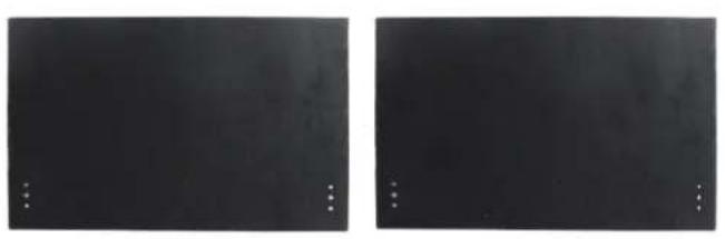
Two identical dark rectangular panels with small white dots at the bottom corners (no text or symbols)2 x Foldable & Detachable Side Wings

natural_image
Two black bicycle wheels with five spokes, shown from top and bottom views (no text or symbols)2 x Wheels

natural_image
Two identical black rectangular panels with circular cutouts, no text or symbols visible.2 x Top side panel Top & Bottom shelves

natural_image
Two identical black L-shaped metal components with metallic joints, shown against a white background (no text or symbols)2 x 5/8" baby pin mount

natural_image
Two black panels with circular features and small white dots, no visible text or symbols2 x Bottom side panel Top & Bottom shelves
natural_image
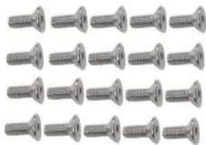
Grid of identical metallic screw fasteners arranged in rows (no text or symbols visible)2 x Countersunk bolts
natural_image
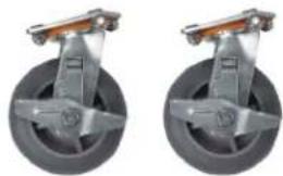
Two identical mechanical components with metallic and gray wheels, no visible text or symbols.2 x Caster wheels with brakes
natural_image
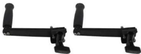
Two black mechanical clamps with lever arms and mounting feet (no text or symbols visible)2 x Handles
natural_image
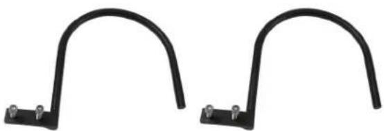
Two black metal bracket clips with mounting holes, no text or symbols visible2 x Cable hooks
natural_image
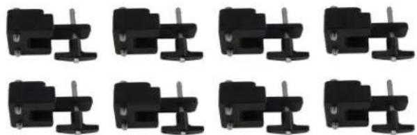
Grid of nine identical black mechanical components with no visible text or symbols8 x Panel connector
natural_image
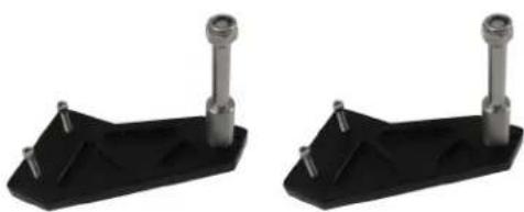
Two identical black plastic mechanical components with metal fittings and mounting holes (no text or symbols visible)2 x Wheel axel
natural_image
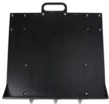
Black rectangular metal plate with mounting holes and a handle (no text or symbols visible)1 x Bottom plate
natural_image
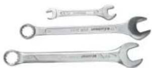
Three metallic wrenches with different end caps, no visible text or markings3 x (10-11, 17, 19) Spanner

natural_image
Two metallic cylindrical mechanical shafts with flanged ends, shown against a white background (no text or symbols visible)2 x 5/8" baby pin

natural_image
Five yellow and red flower-shaped tools with black legs, arranged in descending order (no text or symbols visible)1 x L- Type Allen key (5/16")
5 x T- Type Allen Key
(6mm, 3/16mm, 5mm, 4mm, 2.5mm)
Soundchief Pro Cart Setup
- Loosen the bolt of the Bottom Plate With The help of 5/16"L-type a Allen key and (19) spanner.
- Remove all the bolts of the bottom plate, as shown in the images.
- Align the bottom plate with the main section.

natural_image
Hand using a tool to adjust or install a black metal tray (no text or symbols visible)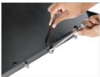
natural_image
Close-up of hands using a tool to adjust or install a metal bracket (no visible text or symbols)
natural_image
Close-up of hands installing or adjusting a black panel with a red circle highlighting the component (no text or symbols visible)
natural_image
Black rectangular electronic component with three metallic connectors at the base (no visible text or symbols)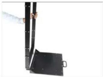
natural_image
Person holding a black metal bracket with a handle, against a white background (no text or symbols visible)- Match the holes of the main section with the bottom plate and insert the bolt.
- With the help of the (5/16") L-Type Allen key, insert the Nyloc nut by holding the bolt.
- Now properly tighten the nut with the help of (19) spanner and (5/16") L-type Allen key.
- Follow the same process for the remaining two bolts and attach the bottom plate with the main section.
- Remove both the wheel axle bolts manually.
- Attach the wheel axle to the side parts of the main section.

natural_image
Close-up of a black metal bracket with mounting holes and a flat base (no text or symbols visible)
natural_image
Close-up of hands installing or adjusting a black metal frame with a red circular marker (no text or symbols visible)
natural_image
Close-up of a hand interacting with a black metal bracket or support panel (no visible text or symbols)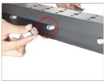
natural_image
Close-up of hands holding a metallic component with a red circle highlighting a small hole (no text or symbols visible)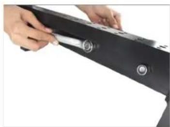
natural_image
Close-up of hands holding a black electronic device with a scroll wheel (no visible text or symbols)
natural_image
Close-up of a black metal frame with perforated edges and a red cable at the base (no text or symbols visible)
natural_image
Close-up of a black metal bracket with mounting holes and bolts (no text or symbols visible)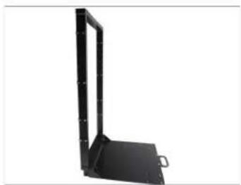
natural_image
Black metal shelf support bracket with mounting bracket (no text or symbols visible)
natural_image
Close-up of hands holding a black mechanical clamp with metal pins (no text or symbols visible)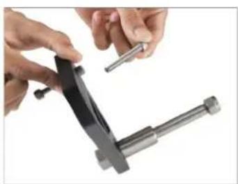
natural_image
Close-up of hands using a tool to adjust a mechanical clamp or bracket (no text or symbols visible)
natural_image
Black mechanical bracket component with a metal lever and mounting holes (no text or symbols visible)
natural_image
Close-up of a hand operating a black mechanical clamp or fixture with a tool, no visible text or symbols.- To attach the wheel axle with the main section, Insert the Nyloc nut by inserting the bolts manually.
- Then tighten it properly with the help of (10-11) spanner and 3/16mm Allen key.
- Remove the Nyloc nut from the wheel axle, as shown in image.
- Remove the Nyloc nut of both the side wheel axles.
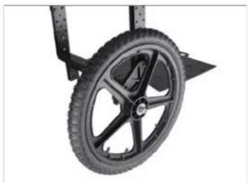
- Attach the wheel to the main section and insert it into the wheel axle, as shown in the image.
- Secure the Nyloc nut by inserting it (19) with the help of a spanner.

natural_image
Person using a wrench to lift a black metal frame (no text or symbols visible)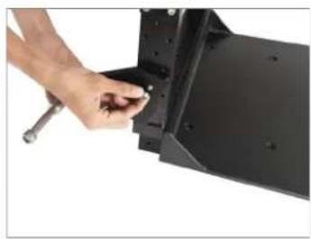
natural_image
Close-up of a hand adjusting a black metal bracket with a wrench (no text or symbols visible)
natural_image
Close-up of hands using a tool to adjust or install a black mechanical component (no visible text or symbols)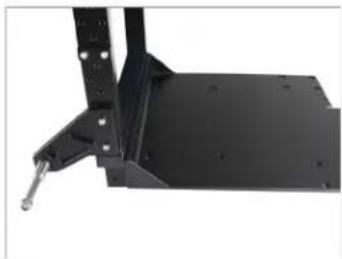
natural_image
Close-up of a black metal frame with a metallic clip and mounting holes (no text or symbols visible)
natural_image
Close-up of a hand using a tool to apply a small component to a black mechanical bracket (no text or symbols visible)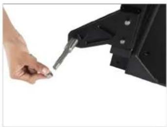
natural_image
Close-up of a hand holding a tool next to a black mechanical component (no visible text or symbols)
natural_image
Black metal frame with support structure and base platform (no text or symbols)
natural_image
Close-up of hands operating a black mechanical device with a coiled cable (no visible text or symbols)
natural_image
Close-up of hands adjusting a black bicycle tire wheel (no text or symbols visible)
natural_image
Close-up of a hand adjusting a black bicycle wheel rim (no text or symbols visible)
natural_image
Close-up of a hand adjusting a black bicycle wheel rim (no text or symbols visible)- 1st wheel is now attached to the main section, follow the same process for the other side wheel.
natural_image
Close-up of a black bicycle wheel with five spokes, mounted on a wheeled cart (no text or symbols visible)
natural_image
Close-up of hands holding a black tire next to a metal frame (no text or symbols visible)- Finally both the wheels are properly attached to the Main section.
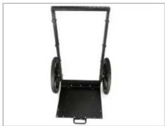
natural_image
Black wheeled cart with two wheels, no visible text or symbols- Remove the caster wheel bolts with the help of a 6mm Allen key and (17) spanner key.

natural_image
Close-up of hands using a tool to adjust or install a car tire (no text or symbols visible)
natural_image
Close-up of hands using a tool to adjust or install a metal component, no visible text or symbols- Remove all bolts of the caster wheels, as shown in the image.

natural_image
Close-up of hands assembling a mechanical component with a tool (no visible text or symbols)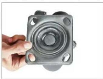
natural_image
Hand holding a metallic mechanical component with a circular top and four mounting holes (no text or symbols visible)- Remove the bolts of both the caster wheels properly.

natural_image
Two identical mechanical components with circular bases and a flat plate, no visible text or symbols.- Insert the bolt matching the thread hole of the caster wheels with the base plate.

natural_image
Close-up of a hand adjusting a black metal frame with a gray wheel, next to a wheeled cart (no text or symbols visible)
natural_image
Person using a wheelwheel to lift a black wheeled cart (no text or symbols visible)• After inserting the bolt, insert the washer and Nyloc nut.
- Now properly tighten them with the help of a 6mm Allen key and (17) spanner.
- Attach the panel connector to the bottom side panel with the help of a 3/16mm Allen key.
- Apply the same process for the other Bottom side panel and attach it with the Panel connector.
- Now both the bottom side panels are ready to use.
- Remove the side bolts of the bottom shelves with the help of a 2.5 mm Allen Key.

natural_image
Close-up of hands installing or adjusting a metal panel on a wheeled platform (no visible text or symbols)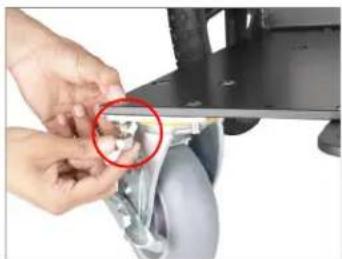
natural_image
Close-up of hands installing or adjusting a mechanical component with a red circle highlighting a detail (no text or symbols visible)
natural_image
Close-up of hands using a tool to lift a mechanical component with a wheel (no visible text or symbols)
natural_image
Black metal handwheel with two wheels, no visible text or symbols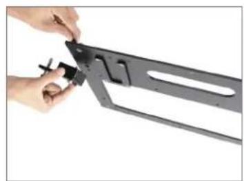
natural_image
Close-up of hands using a metal cutting tool to adjust a black metal bracket (no text or symbols visible)
natural_image
Close-up of hands using a tool to cut a black metal object (no text or symbols visible)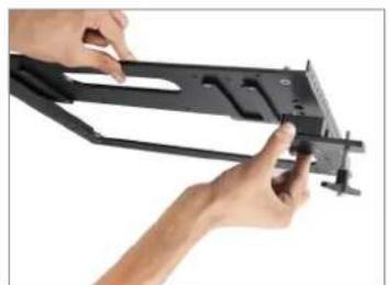
natural_image
Close-up of hands installing a black metal frame component (no text or symbols visible)
natural_image
Close-up of a hand using a red tool to adjust or install a black metal bracket with a circular hole (no text or symbols visible)
natural_image
Hand holding a black metal frame with a handle, against a white background (no text or symbols visible)
natural_image
Hand holding a black metal frame with mounting holes and a handle, against a white background (no text or symbols visible)
natural_image
Dark field image with a bright circular light source and scattered white dots, no text or symbols present.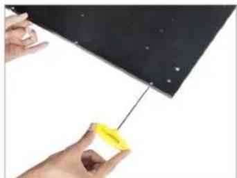
natural_image
Close-up of hands holding a yellow plastic component against a dark surface (no text or symbols visible)- Remove all bolts on the bottom shelves.
- Insert the bolts by attaching the bottom shelves to the bottom side panels.
- Tighten them with the help of a 2.5mm Allen key.
- Follow the same process for another Bottom side panel.
- Remove the Rachet knob by pushing the push pin button.
- Manually remove the Rachet knobs from both the bottom side panels.

natural_image
Close-up of a hand holding a black rectangular object with small circular indentations (no text or symbols visible)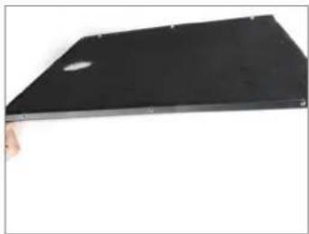
natural_image
Black rectangular electronic device with a small circular mark on top, held by a hand (no visible text or symbols)
natural_image
Close-up of a black metal panel with a hand touching its edge (no text or symbols visible)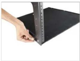
natural_image
Close-up of a hand holding a metal ruler above a black sheet with a flat base (no text or symbols visible)
natural_image
Hand holding a yellow tag attached to a black metal frame structure (no text or symbols visible)
natural_image
Metal frame component with mounting holes and a flat base (no text or symbols visible)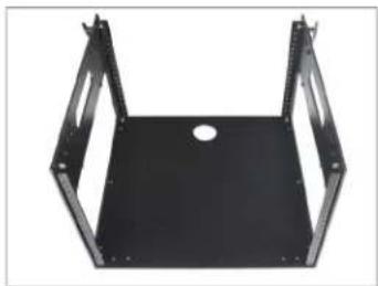
natural_image
Black metal frame structure with mounting holes and a central hole (no text or symbols)
natural_image
Close-up of a hand using a tool to adjust or install a black metal bracket (no visible text or symbols)
natural_image
Close-up of a hand using a tool to adjust or install a mechanical component (no visible text or symbols)
natural_image
Close-up of a hand holding a small tool next to a black metal bracket (no text or symbols visible)- Attach the bottom side panels to the main section of the cart by aligning with it.
- Same as shown in the image.
- Insert the ratchet knob to attach the bottom side panel with the bottom sleeve.
- Secure the bottom side panel with bottom shelves properly with the help of the Rachet knob.
- Remove the knob from the bottom side panel top shelves manually.
- Remove all the knobs of the bottom side panel top shelves.

natural_image
Close-up of a hand placing a black plastic tray into a wheeled cart with two wheels (no text or symbols visible)
natural_image
Close-up of a hand interacting with a black mechanical frame and tire assembly (no visible text or symbols)
natural_image
Close-up of a vehicle chassis frame with visible tires and mounting brackets (no text or symbols)
natural_image
Black wheeled cart with wheels and handle, no visible text or symbols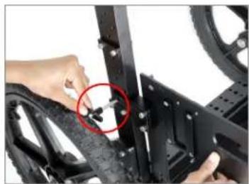
natural_image
Close-up of hands installing a black mechanical component with a red circle highlighting a small component (no text or symbols visible)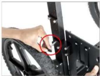
natural_image
Close-up of hands installing a tire component with a red circle highlighting the part (no text or symbols visible)
natural_image
Close-up of hands assembling a black bicycle steering wheel with a red circle highlighting the component (no text or symbols visible)
natural_image
Close-up of a black mechanical frame with visible wheels and mounting brackets (no text or symbols)
natural_image
Dark rectangular image with a single bright circular spot on the top, surrounded by small corner brackets (no text or symbols)
natural_image
Close-up of a hand holding a small object near a dark surface, with a red circle highlighting the point (no text or symbols visible)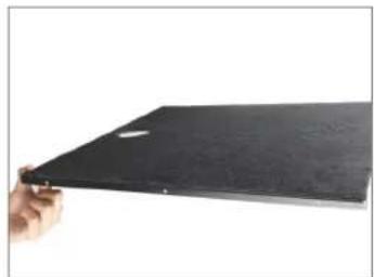
natural_image
Hand holding a black rectangular object against a white background (no text or symbols visible)- Then manually place the bottom shelves of the main section on top of the bottom side panels.

natural_image
Hand holding a black wheeled cart with wheels, no visible text or symbols
natural_image
Black and white photo of a wheeled cart with wheels and a transparent frame (no text or symbols visible)- Tighten them properly with the help of all three knobs.

natural_image
Close-up of a hand inserting a small component into a black metal frame with tires (no text or symbols visible)
natural_image
Close-up of a hand adjusting a black mechanical component with a tire (no visible text or symbols)- Attach the panel connector along the top side panel and tighten it with a 3/16mm Allen key.

natural_image
Hand inserting a small black component into a black metal panel (no text or symbols visible)
natural_image
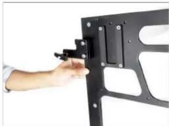
Close-up of a hand holding a red tool next to a black metal bracket with a circular annotation highlighting a small black object (no text or symbols visible)- The panel connector is properly attached with the top side panel.
natural_image
Hand holding a black mechanical bracket with mounting holes (no text or symbols visible)- Tighten the same panel connector on the bottom side and tighten it with a 3/16mm Allen key.

natural_image
Close-up of a person adjusting a black metal bracket component (no text or symbols visible)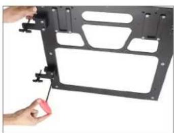
natural_image
Hand inserting a red plastic clip into a black metal frame (no text or symbols visible)- Apply the same process for the Top Panel as well.

natural_image
Hand holding a black plastic panel with mounting holes and connectors (no text or symbols visible)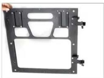
natural_image
Black plastic tray with cutouts and mounting brackets, no visible text or symbols- Remove the side bolts of the Top Side Panel Top & Bottom Shelves with the help of a 2.5mm Allen key.

natural_image
Close-up of a hand using a screwdriver to cut a black textured surface (no text or symbols visible)
natural_image
Hand holding a black rectangular electronic device with a small circular button on top (no text or symbols visible)- Then align with Top side panel.

natural_image
Close-up of a black mechanical component with a circular hole, no visible text or symbols- Align the top side panel with bottom shelves and secure them properly with a 2.5mm Allen key by inserting the bolt.

natural_image
Close-up of a mechanical assembly with mounting holes and a diagonal line (no visible text or symbols)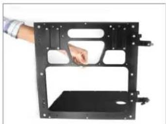
natural_image
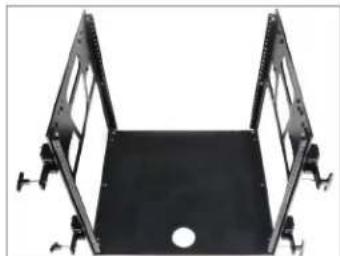
Hand holding a black metal frame with mounting holes and a small inset view (no text or symbols visible)- Apply the same process for the other Top Panel as well.
natural_image
Black metal frame with two symmetric supports and a central hole, no text or symbols visible- Remove the side ratchet knob by pushing the button of the push pin.

natural_image
Close-up of a hand inserting a component into a black metal tray (no text or symbols visible)
natural_image
Close-up of a hand inserting a small black component into a black rectangular device (no visible text or symbols)- Remove the Rachet knob on both sides.

natural_image
Close-up of a hand holding a small mechanical component against a black background (no visible text or symbols)• After attaching the Top Side Panel with Top Bottom Shelves, align with the cart manually.

natural_image
Person assembling a black metal frame structure with two red-circled fasteners (no text or symbols visible)
natural_image
Close-up of a hand inserting a black plastic panel into a black frame (no text or symbols visible)- Secure it from both sides with the help of the Rachet knob.

natural_image
Close-up of a hand using a tool to adjust or install a black mechanical component (no visible text or symbols)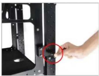
natural_image
Close-up of a hand pressing a small circular mark on a black metal frame (no text or symbols visible)- The Top Side Panel Top & Bottom Shelves are attached to the Soundchief Cart.

natural_image
Black multi-tiered cylindrical cart with wheels, no visible text or symbols- Then place the top side panel on the top, as shown in the image.

natural_image
Hand installing or adjusting a black metal frame structure with a flat top panel (no text or symbols visible)
natural_image
Hand placing a black metal rack frame into a housing (no text or symbols visible)- Secure the top side panel with the help of a knob.

natural_image
Hand installing a black metal frame component with a red circle highlighting the part (no text or symbols visible)
natural_image
Close-up of a black metal frame component with cutouts and mounting holes (no visible text or symbols)- Open the legs of the foldable & detachable side wings and slide them in from the top side panel.

natural_image
Hand placing a black metal frame into a black chassis (no text or symbols visible)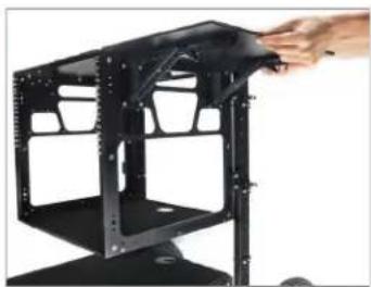
natural_image
Hand placing a black metal frame into a black chassis (no text or symbols visible)NOTE: The side wings can be folded by pushing the lock lever.

natural_image
Close-up of a hand adjusting a black mechanical component with visible teeth and mounting brackets (no text or symbols)
natural_image
Close-up of a hand holding a black mechanical device with visible bolts and mounting brackets (no text or symbols)- Both the side wings are now properly setup, as shown in the image.

natural_image
Black industrial machine chassis with open lid and wheels (no visible text or symbols)- Remove the bolts of the 5/8" baby pin mount.

natural_image
Close-up of hands holding a black mechanical tool with a metallic handle, against a white background (no text or symbols visible)
natural_image
Close-up of hands holding a small metallic tool next to a black mechanical bracket (no text or symbols visible)- Mount the 5/8" baby pin mount to the top of the Soundchief cart.

natural_image
Hand installing a black metal frame component with a ruler, next to a black electronic device (no visible text or symbols)
natural_image
Hand installing or adjusting a black electronic device frame with a metal bracket (no visible text or symbols)- Then by inserting the bolt matching the thread, manually insert the Nyloc nut from the bottom part.

natural_image
Person assembling a black electronic device with tools (no visible text or symbols)
natural_image
Close-up of a hand inserting a black sounder into a device (no visible text or symbols)- Tighten it with the help of a 3/16mm Allen Key and follow the same procedure on the other baby pin mount.

natural_image
Hand inserting a screw into a black server rack (no text or symbols visible)
natural_image
Black industrial machine housing with metal frame and mounting bracket (no visible text or symbols)• Properly remove the handle bolts.
- Align the handle & insert the bolt by matching the handle to the side threads of the main section of the Soundchief cart.
- Then properly tight with the help of a 3/16mm Allen key and (10-11) spanner and follow the same process on the other side handle.
- Loosen the larger side knob in the handle and tighten the knob properly by inserting a 5/8" baby pin.
- Follow the same process on anther side of the handle.
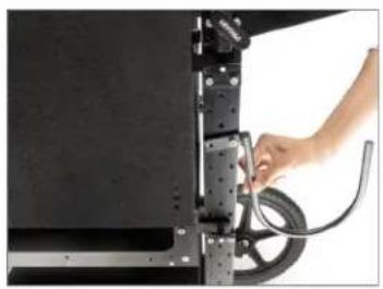
- Properly remove the bolts of the cable hooks, as shown in the image.

natural_image
Close-up of hands adjusting a black mechanical clamp or clip (no text or symbols visible)
natural_image
Close-up of hands holding a black mechanical clamp or clip (no text or symbols visible)
natural_image
Close-up of hands operating a black mechanical device with adjustment knobs (no visible text or symbols)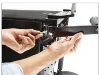
natural_image
Close-up of hands assembling or adjusting a mechanical component (no visible text or symbols)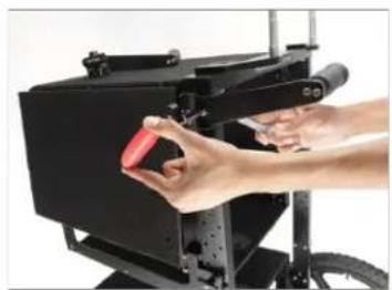
natural_image
Close-up of hands operating a black industrial machine with a red component, no visible text or symbols
natural_image
Black mechanical device with wheels and a rectangular housing (no visible text or symbols)
natural_image
Close-up of a hand inserting a component into a black electronic device (no visible text or symbols)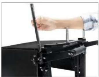
natural_image
Close-up of a hand holding a pen on a black mechanical device (no visible text or symbols)
natural_image
Black industrial machine with metal frame and support structure (no visible text or symbols)
natural_image
Close-up of hands holding a small mechanical tool with a black handle and metallic shaft (no text or symbols visible)
natural_image
Simple black curved line drawing on white background (no text or symbols)- Then insert the bolt by attaching the cable hooks to the cart's main section.
- Insert both the bolts of the cable hooks and tighten them properly with the help of a 3/16mm Allen key and (10-11) spanner.
- Finally, both the cable hooks are properly attached to the Soundchief cart.
- Soundchief Pro cart is finally ready. NOTE: Two people are required to assemble the Soundchief Pro cart.
natural_image
Close-up of a hand adjusting a mechanical component with a coiled cable (no visible text or symbols)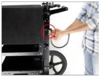
natural_image
Person operating a wheeled electronic device with a red circle highlighting a component (no visible text or symbols)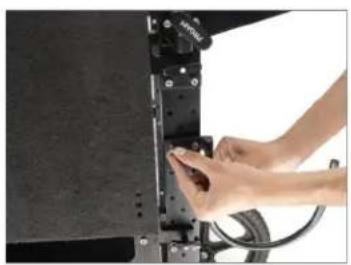
natural_image
Close-up of a hand pressing down on a mechanical component (no visible text or symbols)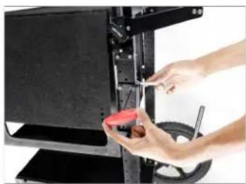
natural_image
Close-up of hands using a tool to adjust or install a mechanical component (no visible text or symbols)
natural_image
Close-up of a black metal rack with visible structural components and a curved arm (no text or symbols)
natural_image
Black and white photo of a multi-wheeled cart with wheels and overhead equipment (no visible text or symbols)
natural_image
Black industrial cart with wheels and handle, no visible text or symbolsYOUR PROAIM SOUNDCHIEF PRO CART ALL DRESSED UP AND READY TO GO!

natural_image
Black wheeled cart with a mounted display and light fixture, no visible text or symbols(SHOWN WITH OPTIONAL ACCESSORIES)
Warranty: We offer one year warranty for our products from date of purchase. Within this period of time, we will repair it without charge for labor or parts. Warranty doesn't cover transportation costs nor does it cover a product subjected to misuse or accidental damage. Warranty repairs are subjected to inspection and evaluation by us.
Liability: We are not liable for damage caused by products that we do not supply or from mishandling in transit, accident, misuse, neglect, lack of care of the product, or service by anyone other than our company.
Contact Us: In case of any kind of dissatisfaction, please Contact us immediately and we promise our utmost support and care until you use our product.

Brand : Proaim
Model : CT-SDCF-PRO
Category : Flat Panel Mount