
Portacom - Intercom System Anchor Audio - Free user manual and instructions
Find the device manual for free Portacom Anchor Audio in PDF.


| Product Type | Portable Intercom System |
| Model | Portacom |
| Brand | Anchor Audio |
| Dimensions (Main Unit) | 8.0 x 4.0 x 2.0 inches (20.3 x 10.2 x 5.1 cm) |
| Weight (Main Unit) | 2.0 lbs (0.9 kg) |
| Power Source | Rechargeable NiMH battery (12V, 2.3Ah) or AC adapter (120V-240V, 50/60Hz) |
| Battery Life | Up to 12 hours continuous use |
| Charging Time | Approximately 4 hours |
| Frequency Range | UHF 500-560 MHz (license-free in many regions) |
| Number of Channels | 10 selectable channels |
| Range (Line of Sight) | Up to 1000 feet (300 meters) |
| Number of Units Supported | Up to 10 units in a party line configuration |
| Audio Quality | Full duplex, noise-canceling microphone, 2W audio output |
| Connectors | AUX input (3.5mm), headset jack (3.5mm) |
| Controls | Volume knob, channel selector, power/mute switch |
| Indicators | Power LED, battery status LED, channel display |
| Operating Temperature | 32°F to 104°F (0°C to 40°C) |
| Charging Method | Multi-unit charging tray (optional) or individual AC adapter |
| Maintenance | Clean with damp cloth; do not use solvents; store in dry place |
| Safety Certifications | FCC, IC, CE compliant; RoHS compliant |
| Spare Parts Available | Battery packs, headsets, belt clips, charging trays |
| Warranty | 2-year limited warranty on main unit, 6 months on battery |
| Recommended Use | Live events, production, education, security, hospitality |
Frequently Asked Questions - Portacom Anchor Audio
User questions about Portacom Anchor Audio
0 question about this device. Answer the ones you know or ask your own.
Ask a new question about this device
Download the instructions for your Intercom System in PDF format for free! Find your manual Portacom - Anchor Audio and take your electronic device back in hand. On this page are published all the documents necessary for the use of your device. Portacom by Anchor Audio.
USER MANUAL Portacom Anchor Audio
natural_image
Exterior view of a mannequin head with portable headphones and two electronic devices (no visible text or symbols)MESSAGE FROM ANCHOR AUDIO
Congratulations on purchasing an Anchor Audio intercom system! You have joined the thousands of satisfied Anchor Audio customers including the various professional athletic teams, prestigious universities, school districts nationwide, first responders, and the branches of the U.S. Military.
From developing our products on giant sticky notes to testing them in the parking lot and driving our neighbors crazy, our hearts - and ears - are 110% committed to delivering reliable battery powered portable sound systems and portable PA systems for you. But we don't stop there. Anchor Audio is proudly manufactured in America and has plenty more solutions for you to choose from: speaker monitors, conference systems, assistive listening, lecterns, and intercoms. We are your best friend in portable sound and are here for you when you need us...or even when you don't. We're just a phone call away. With over 40 years of experience, our Engineering and Production to Sales and Tech Support teams will provide you with the most reliable portable audio products and customer service.
Welcome to the Anchor Audio family! Feel free to contact us at any time. We'd love to hear from you.

Alex Jacobs
President
CONTENTS
GETTING STARTED....1
TROUBLESHOOTING....7
TECHNICAL SPECIFICATIONS 8 - 9
IMPORTANT SAFETY INSTRUCTIONS....10
WARRANTY 11
RETURN AUTHORIZATION PROCEDURES....11
GETTING STARTED
Please check your new unit carefully for any damage which may have occurred during shipment. Each Anchor Audio product is carefully inspected at the factory and packed in specially designed boxes for safe transport.
Notify the freight carrier immediately of any damage to the shipping box or product. Repack the unit in the original box and wait for inspection by the carrier's claim agent. Notify your Anchor Audio authorized dealer of the pending freight claim.
NOTE: All damage claims must be made with freight carrier!
RETURNING SYSTEMS FOR SERVICE OR REPAIR
For service or repair, please call us at 1-800-262-4671 x782 or visit www.anchoraudio.com/technical-support-form.html
Our Technical Support team will help to troubleshoot. If unsuccessful and under warranty, they will issue you a Return Merchandise Authorization (RMA) number. Once you ship your product back to Anchor Audio with the RMA number clearly noted on the box, we will diagnose your unit and repair your unit then ship it back to you. All products must be shipped prepaid. C.O.D. shipments and shipments without an RA number will be refused and returned at your expense.
PORTACOM
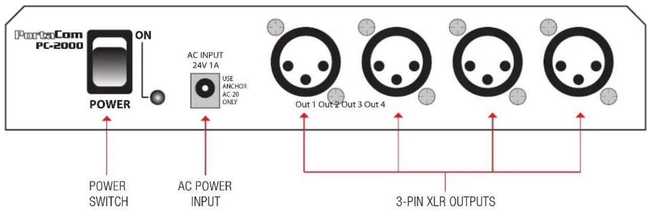
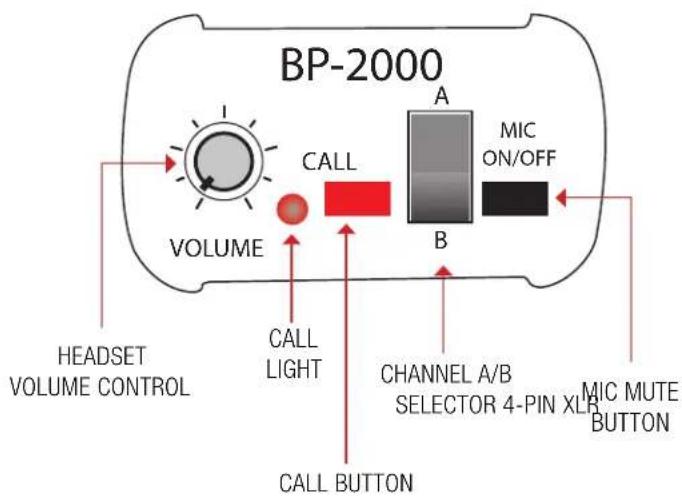
- Plug in headset connector into the 4-pin XLR Headset Input on the BP-2000 belt pack
- Plug in the AC Adapter into a standard 110V AC outlet (230V AC export)
- Connect the BP-2000 belt packs to the output jacks on the PC-2000 using standard microphone cables with 3-pin XLR connectors.
- Set the PC-2000 power switch to "ON"
- Adjust the headset boom so the microphone is close to the mouth
- Adjust the listening level with the headset volume control on belt pack
- Use the Channel Switch to select between channel A or B
NOTE: The optional RM-100 rackmount allows one or two PC-2000s to mount in standard racks.


(PC-2000)
(BP-2000 TOP)
(BP-2000 BOTTOM)

BRANCH BOX (B3-2000)
The PortaCom can be expanded up to 20 users using the Branch Box (B3-2000).
- Follow the PortaCom Basic System Operation instructions on page 2 to initially set up your wired intercom
- Connect a 3-pin XLR cable from the Branch Box XLR input to one of the XLR outputs on the PC-2000 Power Console
- Connect three additional BP-2000 belt packs using standard 3-pin XLR to the Branch Box
- Or if you need additional headsets, connect a 3-pin XLR cable from the current Branch Box to an additional Branch Box
- Repeat as needed until desired setup is complete
NOTE: The PortaCom can be expanded up to 50 belt packs.

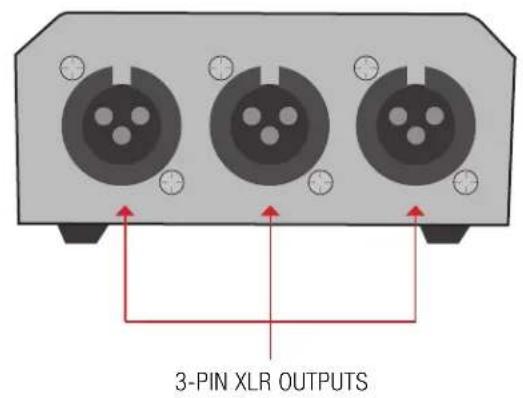
Below is an example of a six user setup using the Branch Box (B3-2000):
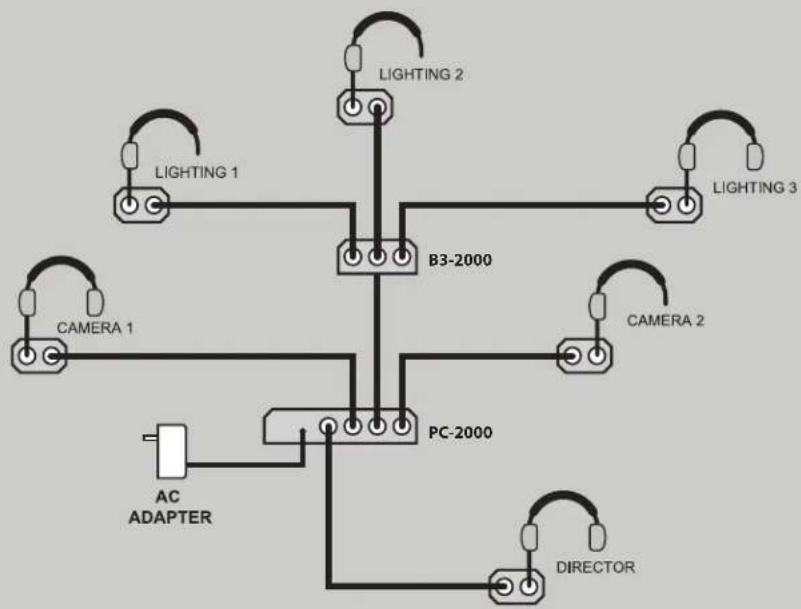
flowchart
graph TD
    A["Lighting 1"] --> B["B3-2000"]
    C["CAMERA 1"] --> B
    D["AC ADAPTER"] --> E["PC-2000"]
    F["LIGHTING 2"] --> B
    G["CAMERA 2"] --> B
    H["DIRECTOR"] --> E
    I["Lighting 3"] --> B
    J["Lighting 2"] --> B
    K["Lighting 3"] --> B
PROGRAM MIXER (PGM-2000)
The PGM-2000 is a two-channel Program Insertion Station for use with the PortaCom wired intercom system. It provides a means to insert program audio (from a tape player, mixer, or stage mics) onto the intercom line.

INTERCOM LINE IN CONNECTOR
The 3-pin female XLR connector accepts the intercom signal from a PortaCom PC-2000 Power Console. This is the standard input for the PGM-2000.
PROGRAM IN CONNECTOR
The 1/4" phone connector accepts the line-level output of a mixer, tape player, etc. and inserts that music/program material onto the connected intercom system.
INTERCOM OUT CONNECTOR
The 1/4" phone connector provides a line-level composite of the intercom signal. Use this output to connect a recorder or a remote amplified speaker.
CHANNEL A/B SWITCH
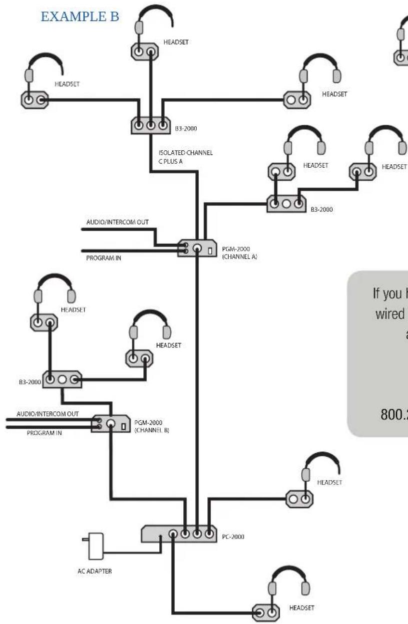
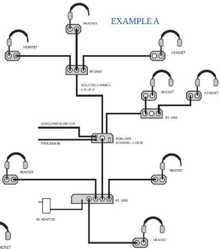
Selects the channel (A or B) which the program material will be inserted in the system. When using the NORMAL A / ISOLATED C output, no program material will be on this output when the channel switch is set to "B" position.
NOTE: Program cannot be inserted on isolated channel C unless a second PGM-2000 is used in the system configuration.
PROGRAM LEVEL SETTING ADJUSTMENT SCREW
Adjusts volume level of inserted program material as heard on the intercom system. Turn clockwise to increase volume of the program material, counterclockwise for lower volume.
POWER LED
Indicator lights when power source is connected to PGM-2000. (There is no power on/off switch - power is supplied and controlled by the system's PC-2000)
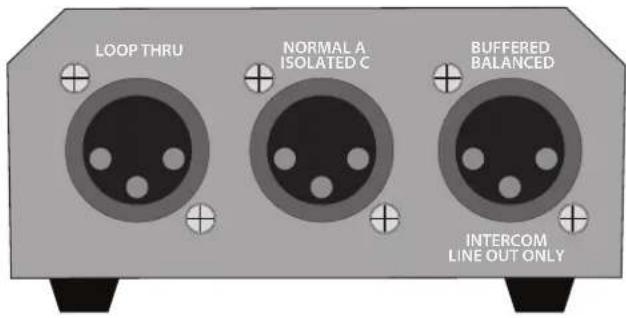
LOOP THRU CONNECTOR
The male 3-pin XLR connector, along with the INTERCOM LINE IN connector, is a composite of the intercom signal and the inserted program material. This jack allows additional belt packs and/or branch boxes to be connected to the intercom system for normal operation.

NORMAL A / ISOLATED C CONNECTOR
Male 3-pin XLR connector. When the CHANNEL SWITCH is set to "A" the output functions like a standard intercom output (of the intercom material). No program material from the system will be inserted on this output when the channel switch is set to "B". Connect belt packs (via B3-2000) to this input for isolated channel C operation.

INTERCOM LINE OUT CONNECTOR
A transformer balanced male XLR-3 connector which has the composite intercom signal and inserted program material, for connection to an alternate location, recorder or mixer.
PROGRAM MIXER (PGM-2000) - CONT'D
Below is a diagram of a typical TV studio set up; the director may use a headset or speaker/gooseneck mic at the station.
flowchart
graph TD
    A["HEADSET"] --> B["B3-2000"]
    B --> C["ISOLATED CHANNEL C PLUS A"]
    C --> D["PGM-2000 (CHANNEL A)"]
    D --> E["AC ADAPTER"]
    D --> F["PC-2000"]
    F --> G["HEADSET"]
    F --> H["HEADSET"]
    I["AUDIO/INTERCOM OUT"] --> D
    J["PROGRAM IN"] --> D
    K["HEADSET"] --> L["B3-2000"]
    L --> M["PGM-2000 (CHANNEL B)"]
    M --> N["AC ADAPTER"]
    O["HEADSET"] --> P["HEADSET"]
    Q["HEADSET"] --> R["HEADSET"]
    S["HEADSET"] --> T["HEADSET"]
    U["HEADSET"] --> V["HEADSET"]
    W["HEADSET"] --> X["HEADSET"]
    Y["HEADSET"] --> Z["HEADSET"]
    style A fill:#f9f,stroke:#333
    style B fill:#ccf,stroke:#333
    style C fill:#cfc,stroke:#333
    style D fill:#fcc,stroke:#333
    style E fill:#cff,stroke:#333
    style F fill:#ffc,stroke:#333
    style G fill:#cfc,stroke:#333
    style H fill:#cfc,stroke:#333
    style I fill:#fcc,stroke:#333
    style J fill:#cfc,stroke:#333
    style K fill:#cfc,stroke:#333
    style L fill:#cfc,stroke:#333
    style M fill:#cfc,stroke:#333
    style N fill:#cfc,stroke:#333
    style O fill:#cfc,stroke:#333
    style P fill:#cfc,stroke:#333
    style Q fill:#cfc,stroke:#333
    style R fill:#cfc,stroke:#333
    style S fill:#cfc,stroke:#333
    style T fill:#cfc,stroke:#333
    style U fill:#cfc,stroke:#333
flowchart
graph TD
    A["HEADSET"] --> B["B3-2000"]
    B --> C["ISOLATED CHANNEL C PLUS A"]
    C --> D["PGM-2000 (CHANNEL A OR B)"]
    D --> E["FC 2000"]
    E --> F["AC ADAPTER"]
    F --> G["HEADSET"]
    G --> H["HEADSET"]
    H --> I["HEADSET"]
    I --> J["HEADSET"]
    J --> K["HEADSET"]
    K --> L["HEADSET"]
    L --> M["HEADSET"]
    M --> N["HEADSET"]
    N --> O["HEADSET"]
    O --> P["HEADSET"]
    P --> Q["HEADSET"]
    Q --> R["HEADSET"]
    R --> S["HEADSET"]
    S --> T["HEADSET"]
    T --> U["HEADSET"]
    U --> V["HEADSET"]
    V --> W["HEADSET"]
    W --> X["HEADSET"]
    X --> Y["HEADSET"]
    Y --> Z["HEADSET"]
    Z --> AA["HEADSET"]
    AA --> AB["HEADSET"]
    AB --> AC["HEADSET"]
    AC --> AD["HEADSET"]
    AD --> AE["HEADSET"]
    AE --> AF["HEADSET"]
    AF --> AG["HEADSET"]
    AG --> AH["HEADSET"]
    AH --> AI["HEADSET"]
    AI --> AJ["HEADSET"]
    AJ --> AK["HEADSET"]
    AK --> AL["HEADSET"]
    AL --> AM["HEADSET"]
    AM --> AN["HEADSET"]
If you have any questions about the setup of your PortaCom wired intercom system, the Program Mixer (PGM-2000), or any other Anchor Audio product, please contact Anchor Audio Technical Support. We are happy to help.
800.262.4671 x782 | techsupport@anchoraudio.com
WINGMAN (WM-500)
The WingMAN 500 is an interface station that allows full duplex communication between ProLink belt packs and unbalanced party-line intercom systems. The ProLink includes a transceiver that operates in a FSK format which is compatible with ProLink belt packs. An integrated interface circuit makes it possible to easily interface the transceiver with party-line intercom systems. This allows users to easily switch communications between one of the two ProLink groups and one of two party line groups.
- Attach the supplied antennas to the front panel jacks
- Connect your wired intercom system to the 3-pin XLR input on the back panel NOTE: Operating power for the WM-500 is obtained from the wired intercom system
- Select wired channel A or B on front panel
- Select wireless channel A or B on front panel
- Turn power switch to ON
- Adjust the headset volume to desired level
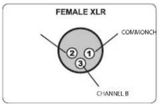
PIN CONFIGURATION
The WingMAN 500 interface connector uses a 3-pin XLR jack on the back panel. Connect the interface box with the wired intercom system using the 3 pin XLR jack on the rear panel.
Pin Configuration
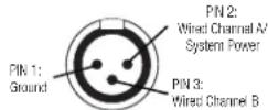
Select Wired Channel (A or B) to be used according to the pin description above (also shown on pack panel). The Wired Channel Switch matches the Anchor Audio PortaCom belt pack channels.


HOW TO SETUP THE WIRELESS TELEX (BTR-700)
Follow the setup instructions below to connect the WingMAN 500 to a BTR-700 Telex wireless base station.
- Connect your BTR-700 (2-wire 3-pin XLR) output to the 3-pin XLR input on the back panel of the WM-500
- Set WingMAN to Wired Channel B on front panel interface
If you have questions about the compatibility of your wired or wireless intercom system and the WingMAN 500, please contact Anchor Audio Technical Support.
FREQUENTLY ASKED QUESTIONS
| FREQUENTLY ASKED QUESTIONS | |
| FAQ ANSWER | |
| Can I use my own headset? | Yes. The ProLink is designed to work with dynamic microphone elements. Shields can be connected to chassis ground pin. Headset pin configuration: 1 = Mic (-), 2 = Mic (+), 3 = Headphone (-), 4 = Headphone (+) |
| How many belt packs can I use? | With the use of branch boxes (B3-2000), the PortaCom has a 50 headset capacity. |
| Can my PortaCom work with wireless intercom systems? | Yes. PortaCom uses the WingMAN 500 as a modular link to a wireless intercom such as the Anchor Audio ProLink. |
| How long of a cable can I use? | We recommend to NOT exceed 200 ft. However, if you need to exceed this length, then heavy-duty cables are recommended. |
HAVING TROUBLE WITH YOUR WINGMAN 500?
| TROUBLESHOOTING | |
| CONDITION | POSSIBLE SOLUTIONS |
| Interference in ProLink Headsets | Switch your belt pack settings to a different ProLink user group A or B. |
| Background Noise Transmitting | Reduce the headset microphone sensitivity level. Adjust the ProLink mic sensitivity blue knob on the belt pack. |
| Transmission Is Weak | Your rechargeable batteries may be running low. If batteries are weak, the Green LED will flash. Your belt pack needs to be recharged. If you need to keep working, you can use disposable alkaline batteries. |
| Proper Intercom Etiquette | WingMAN 500 is an interface station that allows full duplex communication between ProLink belt packs and unbalanced party-line intercom systems. Use proper intercom etiquette - wait to break into the conversation network until the other system users have stopped speaking. |
TECHNICAL SPECIFICATIONS
| PORTACOM WIRED INTERCOM | |
| Normal Line Level | -15 dBV |
| Signal-to-Noise-Ratio | -65 dBV |
| Distortion | < 0.5% |
| Connecting Cables | Standard 1-pair shielded mic cable with 3-pin XLR (heavy-duty cable recommended for runs over 250 ft.) |
| Compatibility | Generally compatible with industry standard system (call for info) |
| PC-2000 - Power Console | |
| Output Connectors | 3-pin XLR - four male |
| Voltage Output | 22V DC to belt packs |
| Max. Current Capacity | 400 mA |
| Max. Belt Packs | 50 BP-2000 belt packs |
| Input Power Reqs. | 24 VAC, 50/60 Hz, 750 mA, 30-40 VDC, 500 mA |
| AC Power Adapter | AC-20 |
| Input Voltage | 120 VAC, 60 Hz |
| Output Voltage / Current | 24 VAC @ 750 mA |
| Dimension (HWD) | 1.75" x 8.5" x 4.5" (4.45 x 21.6 x 10.2 cm) |
| Weight | 3.6 lbs / 1.6 kg |
| Warranty | 2 years |
| BP-2000 - Belt Pack | |
| Input Line Connector | 3-pin XLR female |
| Headset Connector | 4-pin XLR male |
| Bridging Impedance | 10k ohm min |
| DC Current Reqs. | 20 mA max |
| Dimensions (HWD) | 4" x 3.5" x 2" (10.2 x 8.9 x 5.1 cm) |
| Weight | 0.5 lb / 0.22 kg |
| Warranty | 2 years |
| H-2000/H-2000S - Dual Muff / Single Muff Headset | |
| Connector | 4-pin XLR female |
| Microphone Type | Dynamic, low impedance |
| Dimensions (HWD) | 3.5" x 7.4" x 7.9" (8.9 x 18.8 x 20 cm) |
| Weight | Dual: 1 lb / 0.5 kgSingle: 0.8 lb / 0.4 kg |
| Warranty | 2 years |
TECHNICAL SPECIFICATIONS (CONT'D)
PORTACOM WIRED INTERCOM
| B3-2000 - Branch Box | |
| Input | One 3-pin XLR female |
| Output | Three 3-pin XLR male |
| Dimensions (HWD) | 1.9" x 4.1" x 4.25" (4.8 x 10.4 x 10.8 cm) |
| Weight | 1.2 lbs / 0.54 kg |
| Warranty | 2 years |
| PGM-2000- Program Mixer | |
| Channel A/B Connector | 16 - 32V DC on pin 2 with respect to pin 1 |
| Current Drain | 20 mA |
| Input Level | -10 to +4 dBU, 2k impedance |
| Input Frequency Response | 150 Hz - 8 kHz; +0, -6 dBU |
| Output Level | -10 to 0 dBU, 1k driving impedance |
| Output Frequency Response (nominal) | 150 Hz - 8 kHz; +0, -6 dBU(5,000 ft. cable lowers response to 3 kHz |
| Operating Temperature | 32° to 158° F (0° to 70° C) |
| Storage Temperature | -40° to 185° F (-40° to 85° C) |
| Dimensions HWD | 1.9" x 4.25" x 4.1" (50 x 103 x 100 mm) |
| Weight | 2 lbs. (0.9 kg) |
WINGMAN 500
| Wireless Range | US: 200' - 250' |
| Selectable Wireless Groups 2 | |
| Selectable Wired Channels 2 | |
| Frequency | US: 902 - 928 MHz |
| Frequency Settings | 4 per Group |
| Interface Connector | 3-pin female XLR |
| Antenna | 1/2 wave length dipole |
| Antenna Length | 4" (2.54 cm) |
| Dimensions (HWD) | 8.5" x 4.5" x 1.7" (21.6 x 11.4 x 4.32 cm) |
| Weight | 2.4 lbs. / 1.1 kg |
| FCC License | Not Required |
| FCC ID | JBZWM-9000 |
IMPORTANT SAFETY INSTRUCTIONS
1) Read Instructions – All the safety and operation instructions should be read before the product is operated.
2) Retain Instructions – The safety and operating instructions should be retained for future reference.
3) Heed Warnings – All warnings on the product and in the operating instructions should be adhered to.
4) Follow Instructions – All operating and use instructions should be followed.
5) Cleaning – Unplug this product from the wall outlet before cleaning. Do not use liquid cleaners or aerosol cleaners. Use a damp cloth for cleaning.
Exception: A product that is meant for uninterrupted service and that for some specific reason, such as the possibility of the loss of an authorization code for the CATV converter, is not intended to be unplugged by the user for cleaning or any other purpose, may exclude the reference to unplugging the product in the cleaning description otherwise).
6) Attachments – Do not use attachments not recommended by the product manufacturer as they may cause hazards.
7) Water and Moisture – Do not use this product near water – for example, near a bath tub, wash bowl, kitchen sink, or laundry tub; in a wet basement; or near a swimming pool; and the like.
8) Accessories – Do not place this product on an unstable cart, stand, tripod, bracket, or table. The product may fall, causing serious injury to a child or adult and serious damage to the product. Use only with a cart, stand, tripod, bracket, or table recommended by the manufacturer or sold with the product. Any mounting of the product should follow the manufacturer's instructions and should use a mounting accessory recommended by the manufacturer.
9) A product and cart combination should be moved with care. Quick stop, excessive force, and uneven surfaces may cause the product and stand combination to overturn.
10) Ventilation – Slots and openings in the cabinet are provided for ventilation to ensure reliable operation of the product and to protect it from overheating. These openings must not be blocked or covered. The openings should never be blocked by placing the product on a bed, sofa, rug, or other similar surface. This product should not be placed in a build-in installation such as a bookcase or rack unless proper ventilation is provided, or the manufacturer's instructions have been adhered to.
11) Power Sources – This product should be operated only from the type of power source indicated on the marking label. If you are not sure of the type of power supply to your home, consult your product dealer or local power company. For products intended to operate from battery power or other sources refer to the operating instructions.
12) Grounding or Polarization – This product may be equipped with a polarized alternating-current line plug (a plug having one blade wider than the other). This plug will fit into the power outlet only one way. This is a safety feature. If you are unable to insert the plug fully into the outlet, try reversing the plug. If the plug should still fail to fit, contact your electrician to replace your obsolete outlet. Do not defeat the safety purpose of the polarized plug.
13) Power-Cord Protection – Power-supply cords should be routed so that they are not likely to be walked on or pinched by items placed upon or against them, paying particular attention to cords at plugs, convenience receptacles, and the point where they exit from the product.
14) Protective Attachment Plug – The product is equipped with an attachment plug having overload protection. This is a safety feature. If replacement of the plug is required, be sure the service technician has used a replacement plug specified by the manufacturer that has the same overload protection as the original plug.
15) Outdoor Antenna Grounding – If an outside antenna or cable system is connected to the product, be sure the antenna or cable system is grounded so as to provide some protection against voltage surges and built-up static charges. Article 810 of the National Electrical Code, ANSI/NFPA 70, provides information with regard to proper grounding of the mast and supporting structure grounding of the lead in wire to an antenna discharge unit, size of grounding conductors, location of antenna-discharge unit, connection of grounding electrodes, and requirements for the grounding electrode. See Figure A.
16) Lightning – For added protection, unplug this product during a lightning storm, or when it is left unattended and unused for long periods of time, unplug it from the wall outlet and disconnect the antenna or cable system. This will prevent damage to the product due to lightning and power-line surges.
17) Power Lines – An outside antenna system should not be located in the vicinity of overhead power lines or other electric light or power circuits, or where it can fall into such power lines or circuits. When installing an outside antenna system, extreme care should be taken to keep from touching such power lines or circuits as contact with them might be fatal.
18) Overloading – Do not overload wall outlets, extension cords, or integral convenience receptacles as this can result in a risk of fire or electric shock.
19) Object and Liquid Entry – Never push objects of any kind into this product through openings as they may touch dangerous voltage points or short-out parts that could result in a fire or electric shock. Never spill liquid of any kind on the product.
20) Servicing – Do not attempt to service this product yourself as opening or removing covers may expose you to dangerous voltage, other hazards, and potentially void the warranty. Refer all servicing to qualified service personnel.
21) Damage Requiring Service – Unplug this product from the wall outlet and refer servicing to qualified service personnel under the following conditions:
a. When the power-supply cord or plug is damaged.
b. If liquid has been spilled or objects have fallen into the product.
c. If the product has been exposed to rain or water.
d. If the product does not operate normally by following the operating instructions. Adjust only those controls that are covered by the operating instructions as an improper adjustment of other controls may result in damage and will often require extensive work by a qualified technician to restore the product to its normal operation.
e. If the product has been dropped or damaged in any way.
f. When the product exhibits a distinct change in performance – this indicates a need for service.
22) Replacement Parts – When replacement parts are required, be sure the service technician has used replacement parts specified by the manufacturer or have the same characteristics as the original part. Unauthorized substitutions may result in fire, electric shock, or other hazards.
23) Safety Check – Upon completion of any service or repairs to this product, ask the service technician to perform safety checks to determine that the product is in proper operating condition.
24) Wall or Ceiling Mounting – The product should be mounted to a wall or ceiling only as recommended by the manufacturer.
25) Heat – The product should be situated away from heat sources such as radiators, heat registers, stoves, or other products (including amplifiers) that produce heat.
26) Warning: Battery pack or batteries installed shall not be exposed to excessive heat such as sunshine, fire, or the like.
ANCHOR AUDIO WARRANTY
Anchor Audio products are warranted to be free from defects in materials and workmanship for the period of SIX (6) YEARS from the date of original purchase unless listed below.
Warranted for a period of TWO (2) YEARS:
- All wired and wireless microphones, belt pack transmitters, base station transmitters, base station receivers, and hands-free microphones
- All woodworking
• CouncilMAN microphones and bases - PortaCom and ProLink 500 systems in their entirety
• Assistive Listening systems in their entirety
• Accessories, cables, cases, and covers
NOTE: The 'AA' batteries are not covered under warranty by Anchor Audio.
Warranties are subject to the following conditions:
- Product must have been purchased from an authorized Anchor Audio Dealer and have an Anchor Audio serial number
- Anchor Audio must perform or authorize all warranty services or warranty is void
- Warranty is void when equipment is subjected to negligent use, connected to improper power sources, misuse, and/or operation beyond specifications and limits
- Warranty shall not apply to exterior finish, AC power cords, bulbs, or any other failings due to normal wear
- Warranty is void when equipment is subjected to adverse temperature, humidity, moisture, or any condition not considered normal environmental conditions
- Products out of warranty cannot be repaired by Anchor Audio
ANCHOR AUDIO RETURN AUTHORIZATION PROCEDURES
- In all cases, dealers and end users must first obtain approval from Anchor Audio for any product they are attempting to return to Anchor Audio. Upon approval, a Return Merchandise Authorization (RMA) number will be issued by the Anchor Audio Customer Service Department and must accompany all products returned. Clearly note the RMA number on the outside of the box.
- Products returned without approval and an RMA number may be returned to the sender.
- The RMA expires 30 days from date of issue. Any product received after 30 days of the RMA issue date will be returned to sender.
- Products returned must include a RMA number. Product received without an RMA number visibly seen on the box will incur a \$25 processing fee.
- Customer will incur the cost of shipping product to Anchor Audio for any reason. Under warranty repair and/or replacement, Anchor Audio will incur the freight cost to return product to the dealer or customer within the continental U.S.A.
CONTACT US!
5931 Darwin Court | Carlsbad, CA 92008 USA | anchoraudio.com
Technical Support Team
800.262.4671 x 782
techsupport@anchoraudio.com

Sales Team
800.262.4671 x 772
sales@anchoraudio.com
- MESSAGE FROM ANCHOR AUDIO
- CONTENTS
- GETTING STARTED
- RETURNING SYSTEMS FOR SERVICE OR REPAIR
- PORTACOM
- BRANCH BOX (B3-2000)
- PROGRAM MIXER (PGM-2000)
- INTERCOM LINE IN CONNECTOR
- PROGRAM IN CONNECTOR
- INTERCOM OUT CONNECTOR
- CHANNEL A/B SWITCH
- PROGRAM LEVEL SETTING ADJUSTMENT SCREW
- POWER LED
- LOOP THRU CONNECTOR
- NORMAL A / ISOLATED C CONNECTOR
- INTERCOM LINE OUT CONNECTOR
- PROGRAM MIXER (PGM-2000) - CONT'D
- WINGMAN (WM-500)
- PIN CONFIGURATION
- HOW TO SETUP THE WIRELESS TELEX (BTR-700)
- FREQUENTLY ASKED QUESTIONS
- HAVING TROUBLE WITH YOUR WINGMAN 500?
- TECHNICAL SPECIFICATIONS (CONT'D)
- IMPORTANT SAFETY INSTRUCTIONS
- ANCHOR AUDIO WARRANTY
- Warranted for a period of TWO (2) YEARS:
- Warranties are subject to the following conditions:
- ANCHOR AUDIO RETURN AUTHORIZATION PROCEDURES
- CONTACT US!
Brand : Anchor Audio
Model : Portacom
Category : Intercom System