
UPS-RELAY - Inverter Lowell - Free user manual and instructions
Find the device manual for free UPS-RELAY Lowell in PDF.


| Product Type | UPS Remote Monitoring Card (Dry Contact) |
| Model | UPS-RELAY |
| Brand | Lowell |
| Compatibility | Lowell UPS Intelligent Slot |
| Output Connections | DB9 male and terminal block (screw terminals) |
| Relay Ratings | 24V DC, 1A max per relay |
| Dry Contact Type | Form C (SPDT) with jumper selectable active open or active closed |
| Remote Shutdown Input | Accepts 6V, 6mA signal for 3–10s to initiate UPS shutdown |
| Alarm Signals | UPS Failure, Summary Alarm, Bypass Active, Battery Low, UPS On, Utility Failure |
| Number of Relays | 6 |
| Jumper Positions | 6 jumpers (JP1–JP6) for each signal |
| Dimensions (approx) | 100 mm x 70 mm x 20 mm |
| Weight (approx) | 50 g |
| Power Supply | Powered by UPS (no external power needed) |
| Installation | Plugs into Intelligent Slot on UPS rear panel, secured with provided screws |
| Included Accessories | 2 screws, terminal block connector |
| Maintenance | Keep dry, avoid static discharge, clean with compressed air if needed |
| Safety | Follow UPS manual for installation and operation; use only with compatible UPS |
| Spare Parts & Repairability | No user-serviceable parts; contact Lowell for replacement |
Frequently Asked Questions - UPS-RELAY Lowell
User questions about UPS-RELAY Lowell
0 question about this device. Answer the ones you know or ask your own.
Ask a new question about this device
Download the instructions for your Inverter in PDF format for free! Find your manual UPS-RELAY - Lowell and take your electronic device back in hand. On this page are published all the documents necessary for the use of your device. UPS-RELAY by Lowell.
USER MANUAL UPS-RELAY Lowell
UPS-RELAY
Dry Contact Card
Manual
Product Introduction

natural_image
Electronic component with black connectors and a white card, featuring a 19-pin D-sub connector (no visible text or symbols)UPS-RELAY card

natural_image
Close-up of a green and black electronic component with a 10-pin D-sub connector (no visible text or symbols)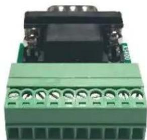
natural_image
Close-up of a green electrical connector with black connectors and pins (no visible text or symbols)Included terminal block accessory, front and rear view
The UPS-RELAY provides Form C relay dry contact closures for remote monitoring of your UPS. For versatility, the UPS-RELAY is capable of selecting Active Open or Active Closed via jumper setting. It also provides for DB9 or terminal block output connections. Suitable applications for this card are listed below:
• IBM Server, Personal PC & Workstations equipment
• Auto-controlled industrial equipment & communication applications
Installation
Step 1: Remove the cover of Intelligent Slot on the rear panel of the UPS, saving the two screws.
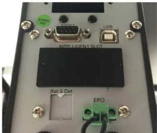
Step 2: Insert UPS-RELAY into Intelligent Slot. Ensure sides of card slide into rails of the card slot.

Step 3: The faceplate of the UPS-RELAY should be against the rear panel. Use a screwdriver to secure the UPS-RELAY to the UPS chassis with the two screws saved in Step 1.

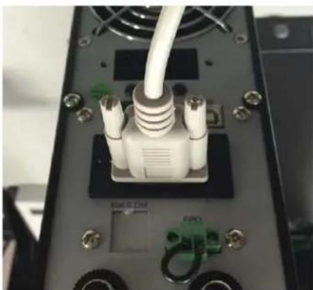
Step 4: Use a 9-pin communication cable to connect monitoring equipment to DB9 or stripped wires to connect to screw terminals, implementing the remote monitoring and control.
natural_image
Close-up of a server rack with a white RJ4 connector and green connectors (no visible text or symbols)
natural_image
Close-up of a green power connector with cooling fans and screw terminals (no visible text or symbols)Specifications
Internal Circuit of DB9 port

flowchart
graph TD
    A["2K/0.1W"] --> B["GND"]
    B --> C["1N4148W"]
    C --> D["Summary Alarm"]
    D --> E["UPS Failure"]
    E --> F["60°"]
    F --> G["Bypass Active"]
    G --> H["70°"]
    H --> I["Battery Low"]
    I --> J["UPS On"]
    J --> K["80°"]
    K --> L["Utility Failure"]
    L --> M["90°"]
    M --> N["Remote Shutdown"]
    N --> O["Common"]
    O --> P["Remote Shutdown (Remote Shutdown Common)"]
    P --> Q["Common"]
DB9 Pin Assignment
| Pin Assignment Function I/O | ||
| Pin 1 UPS Failure Output | ||
| Pin 2 UPS Summary Alarm Output | ||
| Pin 3 GND (Common for Pin 4) Power Ground | ||
| Pin 4 Remote Shutdown Input | ||
| Pin 5 Common for relays Power Supply | ||
| Pin 6 Bypass Active Output | ||
| Pin 7 Battery Low Output | ||
| Pin 8 UPS On Output | ||
| Pin 9 Utility Failure Output |
All relays are rated at 24V, 1A. The shutdown pin (pin4 & pin3) only accepts 3-10s high level signal to perform the UPS shutdown. Signal limited to 6V, 6mA. Otherwise, it's necessary to add one resistor within DC current limitation in the serial loop of Remote Shutdown. (e.g. 2K resistor with at least 0.1W rating power). Refer to the diagrams in Application.
Relay Function Description
| Active Closed Status | Active Open Status | Reason |
| Pin 1 & Pin 5 closed | Pin 1 & Pin 5 open | UPS internal failure |
| Pin 2 & Pin 5 closed | Pin 2 & Pin 5 open | UPS failure, utility failure, low battery, bypass active |
| Pin 6 & Pin 5 closed | Pin 6 & Pin 5 open | Bypass active |
| Pin 7 & Pin 5 closed | Pin 7 & Pin 5 open | Battery voltage is low |
| Pin 8 & Pin 5 closed | Pin 8 & Pin 5 open | UPS is in online/double conversion mode |
| Pin 9 & Pin 5 closed | Pin 9 & Pin 5 open | Utility failure/on battery mode |

Terminal Block Pin Assignment
Application
Below shows the circuit of basic application to implement monitoring and control.

flowchart
graph LR
    A["12V"] --> B["Summary Alarm"]
    A --> C["GND"]
    A --> D["Remote Shutdown"]
    A --> E["Common"]
    B --> F["1"]
    B --> G["6"]
    B --> H["2"]
    B --> I["7"]
    B --> J["3"]
    B --> K["8"]
    B --> L["4"]
    B --> M["9"]
    B --> N["5"]
    F --> O["Bypass"]
    G --> P["Low Battery"]
    H --> Q["UPS On"]
    I --> R["Utility Failure"]
    J --> S
    K --> T
    L --> U
    M --> V
User Interface for 12V

flowchart
graph LR
    A["24V"] --> B["Common"]
    B --> C["Remote Shutdown"]
    C --> D["GND"]
    D --> E["Summary Alarm"]
    E --> F["UPS Failure"]
    F --> G["1"]
    F --> H["6"]
    F --> I["2"]
    F --> J["7"]
    F --> K["3"]
    F --> L["8"]
    F --> M["4"]
    F --> N["9"]
    F --> O["5"]
    P["Bypass"] --> Q["Low Battery"]
    R["UPS On"] --> S["Utility Failure"]
User Interface for 24V
Internal Logic Connection
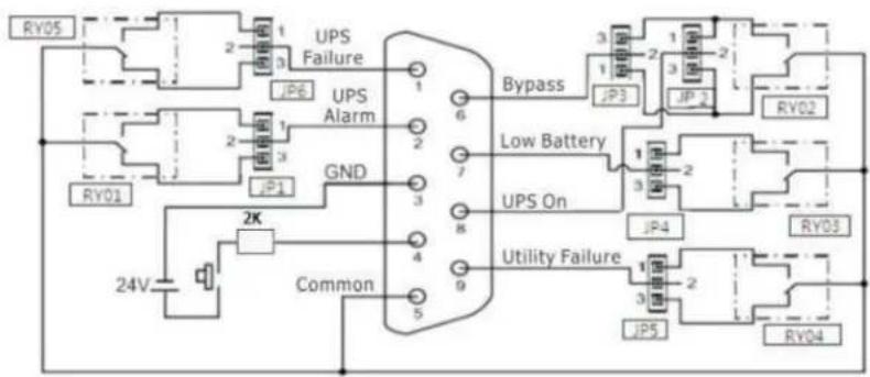
The IC controller of the card controls the actions of 5 relays depending on the UPS status. Active Closed terminal and Active Open terminal of each relay connect to Pin 3 and Pin 1 of a 3-pin connector respectively. Pin 2 of the 3-pin connector connects to the signal pin of the DB9 interface connector. The 2-pin jumper can be plugged to the 3-pin connector to either connect Pin 1 & Pin 2 (Active Closed) or Pin 3 & Pin 2 (Active Open).
flowchart
graph TD
    A["24V"] --> B["2K"]
    B --> C["Common"]
    C --> D["UPS Failure"]
    D --> E["JP6"]
    D --> F["JP3"]
    D --> G["JP1"]
    D --> H["JP5"]
    D --> I["JP2"]
    D --> J["JP1"]
    D --> K["JP01"]
    D --> L["JP02"]
    D --> M["JP03"]
    D --> N["JP04"]
    D --> O["JP05"]
    D --> P["Low Battery"]
    D --> Q["UPS On"]
    Q --> R["JP4"]
    Q --> S["JP5"]
    Q --> T["JP6"]
    Q --> U["JP7"]
    Q --> V["JP8"]
    Q --> W["JP9"]
    Q --> X["JP10"]
    Q --> Y["JP11"]
    Q --> Z["JP12"]
    Q --> AA["JP13"]
    Q --> AB["JP14"]
    Q --> AC["JP15"]
    Q --> AD["JP16"]
    Q --> AE["JP17"]
    Q --> AF["JP18"]
    Q --> AG["JP19"]
    Q --> AH["JP20"]
    Q --> AI["JP21"]
    Q --> AJ["JP22"]
    Q --> AK["JP23"]
    Q --> AL["JP24"]
Pin definition and internal logical connection
Accordingly, if Pin 1 connects with Pin 2 via the jumper, the status of dry contact signal will be Active Closed, refer to the diagram below. When the signal is active, the signal pin on the DB9 connector will connect with the common Pin (Pin 5) via the relay.

flowchart
graph TD
    A["RY05"] --> B["2"]
    B --> C["3"]
    C --> D["UPS Failure"]
    D --> E["JP6"]
    E --> F["1"]
    F --> G["2"]
    G --> H["3"]
    H --> I["2"]
    I --> J["1"]
    J --> K["3"]
    K --> L["2"]
    L --> M["1"]
    M --> N["3"]
    N --> O["2"]
    O --> P["1"]
    P --> Q["3"]
    Q --> R["2"]
    R --> S["1"]
    S --> T["3"]
    T --> U["2"]
    U --> V["1"]
    V --> W["3"]
    W --> X["2"]
    X --> Y["1"]
    Y --> Z["3"]
    Z --> AA["2"]
    AA --> AB["1"]
    AB --> AC["3"]
    AC --> AD["2"]
    AD --> AE["1"]
    AE --> AF["3"]
    AF --> AG["2"]
    AG --> AH["1"]
    AH --> AI["3"]
    AI --> AJ["2"]
    AJ --> AK["1"]
    AK --> AL["3"]
    AL --> AM["2"]
    AM --> AN["1"]
    AN --> AO["3"]
    AO --> AP["2"]
    AP --> AQ["1"]
    AQ --> AR["3"]
    AR --> AS["2"]
    AS --> AT["1"]
    AT --> AU["3"]
    AU --> AV["2"]
    AV --> AW["1"]
    AW --> AX["3"]
    AX --> AY["2"]
    AY --> AZ["1"]
Connection for Active Closed
If Pin 3 connects with Pin 2 (Active Open) via the jumper, the status of dry contact signal will be Active Open, refer to the diagram below. When the signal is active, the signal pin on the DB9 connector will disconnect with the common Pin (Pin 5) via the relay.

flowchart
graph TD
    A["24V Power Supply"] --> B["2K Control"]
    B --> C["Common"]
    C --> D["UPS Failure"]
    D --> E["JP6 Alarm"]
    E --> F["Ground"]
    G["Utility Failure"] --> H["JP5"]
    H --> I["JP4"]
    I --> J["JP3"]
    J --> K["Low Battery"]
    K --> L["JP2"]
    L --> M["JP1"]
    M --> N["Ground"]
    O["24V Power Supply"] --> P["24V Control"]
    P --> Q["24V Signal"]
    R["24V Power Supply"] --> S["24V Control"]
    S --> T["24V Signal"]
    U["Bypass"] --> V["JP3"]
    V --> W["JP2"]
    W --> X["JP1"]
    X --> Y["Ground"]
    Z["24V Power Supply"] --> AA["24V Control"]
    AA --> AB["24V Signal"]
Connection for Active Open
Jumper Set-up
The jumpers can be easily found just behind the relays.

natural_image
Close-up of an electronic circuit board with various components and a RoHS indicator (no readable text or symbols beyond labels)Pin 1 of jumper connection is located closest to the rear of the card. Pin 3 of the jumper connection is closest to the relays.

To achieve Active Closed dry-contact signal, the jumper should connect Pin 1 and Pin 2 as shown below.

Jumper setting for Active Closed
To achieve Active Open dry-contact signal, the jumper should connect Pin 2 and Pin 3 as shown below.

Jumper setting for Active Open
Jumper Functional Description
| JP Description JP Description | ||
| 1 UPS Alarm (DB9, Pin 2) 4 Low battery (DB9, Pin 7) | ||
| 2 UPS on (DB9, Pin 8) 5 Utility failure (DB9, Pin 9) | ||
| 3 Bypass (DB9, Pin 6) 6 UPS failure (DB9, Pin 1) |
Remote Shutdown Functional Description
To enable remote shutdown, apply ground to Pin 3 and 6V Pin 4 for a period of 3 to 5 seconds. UPS will shutdown 5 seconds later for a period of 5 seconds. UPS will auto restart after the 5 second shutdown, even if shutdown signal is still applied.
Brand : Lowell
Model : UPS-RELAY
Category : Inverter