
M29TZ-SM99CL-BTW1 - Microscope Swift - Free user manual and instructions
Find the device manual for free M29TZ-SM99CL-BTW1 Swift in PDF.


| Brand | Swift |
| Model | M29TZ-SM99CL-BTW1 |
| Product Type | Digital Microscope |
| Magnification Range | 10x - 200x (optical) up to 1000x (digital) |
| Illumination | Adjustable LED with built-in light source |
| Display | Integrated 4.3-inch LCD screen |
| Image Capture | Photo and video recording (supports microSD card up to 32GB) |
| Connectivity | USB 2.0, Wi-Fi, Bluetooth (for wireless streaming) |
| Power Supply | Rechargeable lithium-ion battery (3.7V, 2000mAh) or USB-C |
| Dimensions (L x W x H) | 18.5 cm x 12.0 cm x 7.5 cm |
| Weight | Approx. 420 g |
| Focus Adjustment | Coarse and fine focus knobs |
| Stage | Dual-layer mechanical stage with slide clips |
| Software | Compatible with Windows/Mac software for measurement and annotation |
| Cleaning Instructions | Use lens cleaning paper and soft cloth; avoid solvents |
| Safety Warnings | Do not look directly at the LED; keep away from water; use only specified charger |
| Spare Parts | Replacement bulbs, slides, dust cover available from manufacturer |
| Repairability | User-replaceable battery and bulb; contact support for other repairs |
Frequently Asked Questions - M29TZ-SM99CL-BTW1 Swift
User questions about M29TZ-SM99CL-BTW1 Swift
0 question about this device. Answer the ones you know or ask your own.
Ask a new question about this device
Download the instructions for your Microscope in PDF format for free! Find your manual M29TZ-SM99CL-BTW1 - Swift and take your electronic device back in hand. On this page are published all the documents necessary for the use of your device. M29TZ-SM99CL-BTW1 by Swift.
USER MANUAL M29TZ-SM99CL-BTW1 Swift
Swift M29TZ-SM99CL-BTW1
Microscope
Use and Care Manual
M29TZ-SM99CL
The Swift M29TZ zoom stereo microscope is ideal for laboratory, industrial and educational use. The M29TZ is designed to produce a crisp image (erect) with a generous field of view and an excellent depth of focus. It features zoom objectives with continuous magnification ranges from 10X to 40X which is not possible with a fixed power stereo microscope.
| Model Number | M29TZ |
| Objectives | 1X - 4X |
| Eyepieces | W10X, FN23 |
| Total Magnification/ Field of View | 10X - 40X / 23mm - 5.75mm |
| Working Distance | 80mm |
| Stand | SM90CL |
| SM90CL Illuminator (incident & transmitted) | 3W, 5500K LED |

Stereoscopic microscopes are designed for viewing 3-dimensional objects, inspection or assembly of small parts, and for dissection of biological specimen at low magnification. The 35^ inclined viewing head provides an upright, unreversed image which permits easy manipulation of object being viewed while looking through the microscope. The incidental and transmitted illuminators incorporate high intensity 3 watt LED lamps.
For optimum viewing satisfaction, follow these simple procedures. Nomenclature used to describe components and controls can be identified by referring to the diagram at left.
UNPACKING
Remove and unpack box containing post stand with 90mm diameter black/white contrast plate installed from master carton, along with AC power cord. Remove and unpack box containing zoom head assembly, one pair of eyepieces, 2 each rubber eyeshields, 0.90mm and 2mm "L" hex key wrench, 95mm frosted stage plate and dust cover.
- Make certain not to touch any of the lens surfaces while handling the microscope. Dust, dirt, fingerprints can damage the delicate lens surfaces or adversely affect image quality.
- Examine packing material before you discard it. Retain the packing boxes in case you need to transport, store, or return the microscope for service. If it becomes necessary to ship the microscope for any reason, pack it in the original boxes and then pack these boxes in outer corrugated shipping container for optimum protection. Use of the inadequate packing will not provide adequate protection in transit, and will void your warranty.
ASSEMBLY
Place the microscope post stand on a flat stable and clean surface.
- Mounting the focusing assembly to the microscope post stand.
A. Tighten support collar locking screw located on post stand.
B. Loosen focusing block locking screw locate on back of focusing block
C. Slide focusing block over 32mm diameter vertical post of stand
D. Tighten focusing block locking screw
- Mounting stereo zoom head to stand.
A. Loosen head locking screw.
B. Insert head into the stand (do not force), positioning head to face either forward or backward, whichever suits your preference or needs.
C. Tighten head locking screw.
-
Install rubber eyepiece shields over top of eyepieces.
-
Connect the coaxial plug, from incidental illuminator, into power jack located on top of 32mm diameter post.
-
Plug your IEC power cable into the IEC port located on rear of microscope base and the other end of the AC cord into appropriate 100 to 240 volt AC outlet.
OPERATION
1. ILLUMINATION
A. The microscope is furnished with two stage plates. The frosted glass plate is used when viewing transparent specimen slides or for viewing some specimen thin enough through which light can pass (insect wings, etc.) The plastic black/white contrast plate can be used when viewing opaque objects or for dissecting. Choose side of plate providing best contrast with specimen.
To change plates, remove black/white stage plate by putting finger in relief and press edge of stage plate to the front of base and remove plate. Install frosted glass stage plate by inserting into opening and pressing forward and down into base.
B. There are two rocker type light controls located on the rear top surface of microscope base. “I” = Turns incidental light ON and OFF (top illumination) “II” = Turns transmitted light ON and OFF (sub stage illumination)
C. Light intensity control located on side of base. This control varies the light intensity of either the transmitted or incidental LED illuminators.
D. Select and push appropriate rocker switch to ON position to turn desired incidental or transmitted illuminators on.
E. Adjust brightness of LED illuminator with intensity control knob located on side of microscope, rotating control varies intensity of both transmitted and incidental illuminators.
2. INTERPUPILLARY ADJUSTMENT
This permits each user to adjust spacing between eyepieces in order to accommodate distance between their eyes. While looking through the microscope eyepieces with both eyes grasp eyepiece tube housings with both hands and rotate them on their axis, moving eyepieces apart or together until a full field of view is observed and images blend into one. Interpupillary distance is now corrected for your own inter-ocular distance and does not require further adjustment later unless another user changes this adjustment.
3. FOCUSING
A. Adjust zoom control knobs (located on both sides of head) so that the lowest magnification number "1" is positioned at the black index dot on head. Lower magnifications have larger fields of view, making it easier to position and locate area to be viewed.
B. Place a flat object or specimen slide (cover glass up), on stage plate.
C. Position focusing knobs in the center of focusing range.
D. On post mounted models, the height of viewing head can be adjusted up or down on the post in order to focus on difference sized objects. Loosen the locking knob located on the locking support collar, allowing the support collar to slide down to bottom of post. While firmly holding viewing head with one hand, loosen locking knob located on back of focusing assembly so that head can move freely up or down on post.
While looking through microscope, move viewing head up or down on post until object can be seen in approximate focus. Tighten focusing assembly locking knob. Position the support collar under the focusing block and tighten locking knob on support collar. It is not necessary to make this adjustment every time you change objects to be viewed, so long as the different objects are of similar thickness or height.
E. Both eyepieces have knurled diopter adjustment rings. Rotate both left and right diopters in a clockwise direction to the lowest position.
F. Adjust zoom control to the highest magnification by aligning the number "4" on knob to the black index dot on head.
G. While looking through right eyepiece with one eye, rotate focusing control knob until specimen comes into sharp focus through right eyepiece.
H. Adjust zoom control knob to the lowest magnification.
I. Adjust the right diopter until the image is sharp. Do not change the focusing knob position.
J. Without changing the position of the focusing knob, adjust the left eyepiece diopter until you obtain a sharp image in left eyepiece. The image should now be sharp throughout the zoom power range.
SPECIFICATION CHART
| Eyepieces | Zoom Objective Position | Standard Objective 1 (supplied) | |
| Working Distance – 79mm | |||
| Total Magnification | Field Size | ||
| WF10XField No. 20Interpupillary Distance54~78 | 1X | 10X | 20mm |
| 2X | 20X | 10mm | |
| 3X | 30X | 6.7mm | |
| 4x | 40X | 5mm | |
4. ADAPTING C-MOUNT CAMERA to microscope (Trinocular Model Only)
This microscope is equipped with a port on top of binocular head. Take the c-mount provided with your microscope and attach it to the bracket camera.
Locate knurled screw located at the front of trinocular port on head. Turn knurled locking screw in a counter clockwise direction to loosen screw and to permit removal of black plastic disk covering trinocular port.
Insert video adaptor tube into trinocular port. If adapter does not insert easily, further loosen knurled screws at side of port until adaptor tube drops into port and is firmly seated. Retighten knurled screw to secure adaptor and camera in place. Pull sliding rod until fully extended, to direct microscope image to trinocular port.
These models are also equipped with a sliding rod located on the backside of the head. When this rod is pushed completely into the head, the microscope image is directed 100% into both eyepieces of the microscope. When his rod is pulled as far as possible away from the head, the microscope image is directed into the trinocular post. You will still be able to observe image through right eyepiece, but no image will be visible through left eyepiece.
MAINTENANCE
WARNING: For your own safety, turn switch off and remove plug from power source before maintaining your microscope. If the power cord is worn, cut or damaged in any way, have it replaced immediately to avoid shock or fire hazard.
1. OPTICAL MAINTENANCE
A. Do not attempt to disassemble any lens components. Consult a microscope service technician when any repairs not covered by instructions are needed.
B. Prior to cleaning any lens surface, brush dust or lint off lens surface using a camel hair brush. You can also use an ear syringe or canned compressed air, such as that sold by most computer stores.
C. To clean eyepiece lenses, do not remove from eyepiece tube. Clean only the outer lens surface. Breath on lens to dampen surface, then wipe with lens paper or tissue or use a cotton swab moistened with distilled water. Wipe lenses with a circular motion, applying as little pressure as possible. Avoid wiping dry lens surface as lenses are scratched easily. If excessive dirt or grease gets on lens surfaces, a small amount of Windex can be used on a cotton swab or lens tissue. To clean objective lenses, do not remove objectives from microscope. Clean front lens element only, following same procedure.
A. First remove the glass/plastic stage plate from the top of the base stand.
B. Inside you will notice the 3-Watt LED bulb.
C. Using a Phillips screw driver remove two each 3mm Phillips head screws securing the LED to heatsink plate.
D. Using a Philips screw driver, remove the 4 rubber feet screws securing black plastic illuminator base to the microscope pole -base.
E. Carefully unplug the LED bottom light connector (attached to socket marked LED) from circuit board.
F. Remove LED bulb through the heatsink plate and replace assembly with #800-425 LED bulb.
G. Replace lamp mounting screws (2 ea), light housing screws (3ea), lamp bracket mounting screws and nuts (2ea)
H. Carefully plug the LED bottom light connector into socket marked LED on circuit board.
The extra long life LED incidental (top) illuminator bulb must be replaced at the factory. Remove the microscope focusing block by loosening the black knurled knobs located on the back side of the post and unplug the power cord from the vertical post. Return the focus block to National for replacement of the LED bulb.
OPTIONAL BRACKET / CAMERA ASSEMBLY
Your M29TZ-SM99CL microscope is equipped with a C-Mount lens, which when paired with a Motic Digital Table or Camera allow for digital microscopy.
- Take the plastic trinocular cap of the top of the trinocular port.
- Then take you're the C-Mount, supplied with your microscope and screw into your Motic Digital device.
- Slide the C-Mount down into the trinocular port and tighten the C-Mount locking screw to secure your Motic digital device.
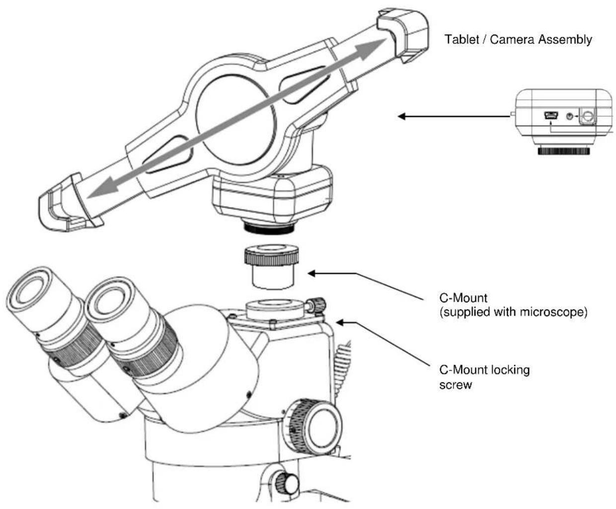
M29TZ-SM99CL-BTW SERIES

CONNECTING THE CAMERA TO BTW8 AND BTW10 TABLET
- Connect the tablet to the camera: *Image of BTW camera may differ, but connection is the same*
BTW8 and BTW10
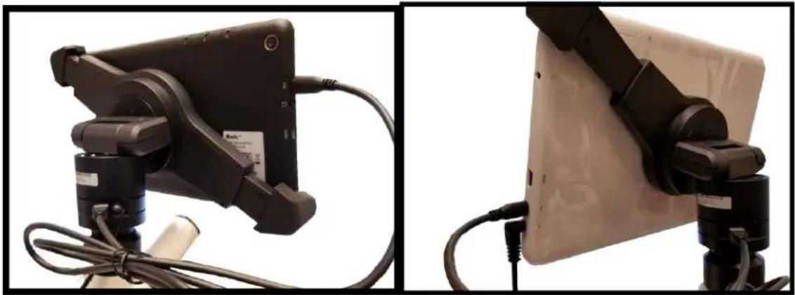
natural_image
Two views of a portable electronic device mounted on a stand, showing cable and wiring (no visible text or symbols)- Plug the charger in and insert the power DIN cable. Power charger appearance may differ slightly from model to model.
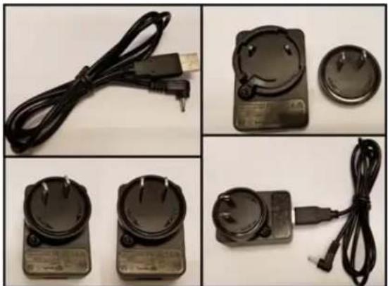
natural_image
Four-panel photo collage showing connected cables and accessories, no visible text or symbols- Plug the power DIN into the back of the camera – The power plug is very snug, make sure it is properly inserted

natural_image
Close-up of a connector being inserted into a white socket, showing cable and plug details (no text or symbols visible)NOTE: This connection cannot be loose – insert completely: BTW8 Connection Shown Below

natural_image
Close-up of a black mechanical component with a red arrow pointing to a specific area, shown from two angles (no text or symbols visible)- Wait 2 minutes and press the power button once –
BTW8
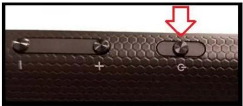
natural_image
Close-up of a black textured surface with three switches labeled I, +, and G, and a red downward arrow pointing to the G button (no text or symbols beyond labels)BTW10

natural_image
Close-up of a white electronic device's top panel with a red arrow pointing to a button, showing no text or symbols.- You should see this 0% (if the battery is completely discharged)
Note: if you never see this image after pressing the power button: Connect the power pack and micro-USB into the tablet directly. Wait 2 minutes and try again.

- After about 30 to 45 minutes, press the power button one time and wait for battery indicator to appear. It should show the battery beginning to take charge.
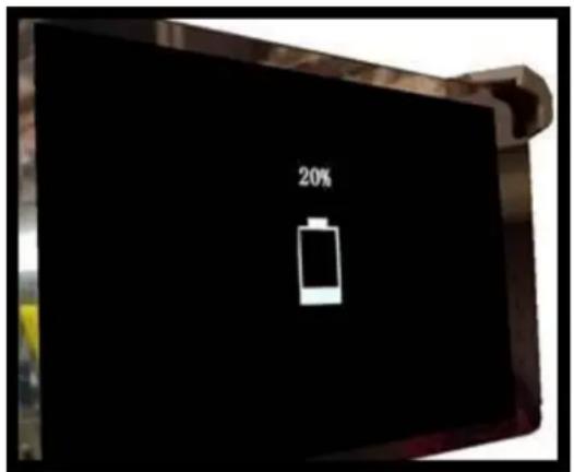
- With the battery indicator on the screen, hold down the power button until it disappears. Let go of the power button and wait a couple of seconds until the Motic Logo appears.
- The Motic Logo screen will appear first, then the main tablet screen will appear.
- As long as the power cable is plugged into the back of the camera, the tablet will trickle charge, and continue to function.
- If you choose to unplug the camera from the charger, the camera will be running on the tablet battery.
- On a fully charged tablet battery, both camera and tablet will run for approximately 2hrs only.
TABLET ACCESSORIES

natural_image
Product photo showing a Kingston 1000 card, a power cord cable, and USB charger with a small card, all without visible text or symbols.| HDMI Cable | This cable will enable you to connect to an HDMI ready device, to view your tablet on a larger format. The displayed image will replicate the displayed image of the tablet. |
| Power Adapter | This 5V DC power adapter is for charging your tablet's battery. It is also used to power the camera in WiFi mode. |
| Calibration Slide | This slide will enable you to calibrate your tablet to your microscope, for accurate measurements. You do not need to calibrate your microscope in order to begin using your table/microscope. |
| C-Ring | This ring is used between the camera and c-mount to achieve par-focus. Pre-installed on MA15602 – C-Mount. |
| 4GB Micro-SD | This storage card can be used with your tablet to store images and then transfer them to your computer. This card is provided as a courtesy and cannot be replaced. *32GB Max Supported* |
| Mini USB to Micro USB | Provides power and feed connection between the tablet and camera. To operate the camera, move the switch to the camera position. |
| USB to Micro USB | This cable when used in conjunction with the power adapter is used to charge the tablet. |
| USB to Mini Power Din | This cable is used to power the camera, in WiFi mode. This cable can also be used to charge both the tablet and camera at the same time. Keep plugged into camera at all times, if possible. |
| L-Wrench | Optional Wrench for mounting bracket to Motic branded trinocular microscopes |
TABLET OPERATION - BTW8 (top) - BTW10 (bottom)

| - | Volume adjustment - decrease |
| + | Volume adjustment - increase |
| G | Hold for a few seconds to turn unit on |
| Micro USB Port for charging tablet and connecting to bracket camera | |
| Provides sound via earphone/speaker | |
| HDMI | Connects to HD ready device via HDMI cable |
| Micro SD | Micro SD Card Slot for storing images on Micro SD Card (4GB included) |

POWER MANAGEMENT BTW 8 and BTW 10
Power to the BTW camera is supplied via the coiled USB cable provided with this product. Since the tablet batteries must supply power for both the tablet and camera simultaneously, approximately 2hrs of continued used can be expected. 8hrs of recharging is required to replenish the tablet battery. So allowing it to charge overnight is highly recommended.
- Camera connected to tablet, supplying power via USB:

natural_image
Close-up of a black mechanical component with a threaded connector (no visible text or symbols)
If more than two hours of continuous use is required, use the supplied wall charger and power cable included with your tablet. Leaving the power charger connected to the camera will trickle charge the tablet. This will be a much slower rate, but should allow time beyond 2hrs.
- Camera connected to both tablet and wall charger: Trickle charging tablet via USB.

natural_image
Close-up of a black mechanical component with a threaded pipe and base, no visible text or symbols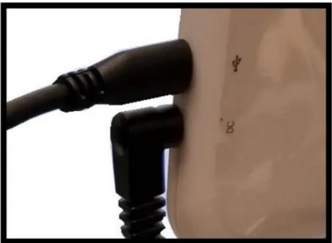
natural_image
Close-up of a black plug inserted into a white container, no visible text or symbolsCONNECTING THE BTW TABLET TO EXISTING WIRELESS NETWORK
The BTW camera has the unique ability to connect to your existing network system using the MoticHub feature.
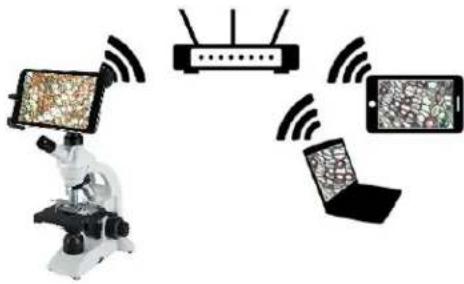
- On the home screen of the tablet select the Settings icon.

- Select WiFi within the Settings window.

- Find your Work/Home WiFi SSID and connect. *turn WiFi on if turned off* Note: In this case I have selected National.


- Now you have added the tablet to your WiFi network
- On the home screen of the tablet select the MotiConnect app.

- Then select the MoticHub icon and MoticHub will launch.

natural_image
Microscopic view of plant cells with red-stained cell walls, no visible text or symbols- Turn MoticHub On.

- MoticHub will create an IP address for the tablet on your network.
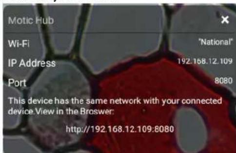
- Write down the generated IP address, you will need this to connect your WiFi enabled device/tablet/phone/computer/laptop.
- Now any tablet or computer/laptop connected to your network will have access to your live image.
Connecting your WiFi enabled device to the BTW tablet
- Make sure you are first connected to your office/home WiFi network.
- Download the MotiConnect app from the App Store, Google Play, or Chrome Store, to your android or apple device/tablet/phone.
- Start the MotiConnect application.
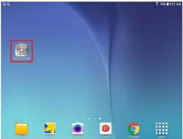
- Click on the Camera Device button at the top right hand of the screen.

- Click on the Add button on the pop up window

- You may give your New Device any name, however the IP Address must be same as the IP generated by Motichub.
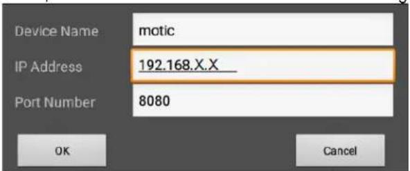
- Now select your New Camera

- You can now view the image live on the MotiConnect app as well as capture, measure and annotate the image using the tools provided.

Connecting your WiFi enabled computer/laptop to the BTW camera connected to your local network
- Install the Motic Images software into your computer or laptop.
- Start the Motic Images application – Click File – Click Capture
- The Motic Live Imaging window will open.

- The Video Device box should have the Moticam X selected.


- Click on Open to open the Moticam X IP address box.
- In the open Moticam X IP address box type in the IP address generated by the MoticHub feature of the BTW tablet.
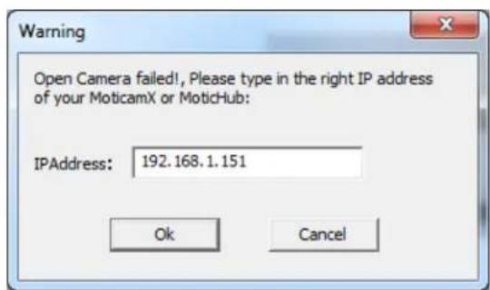
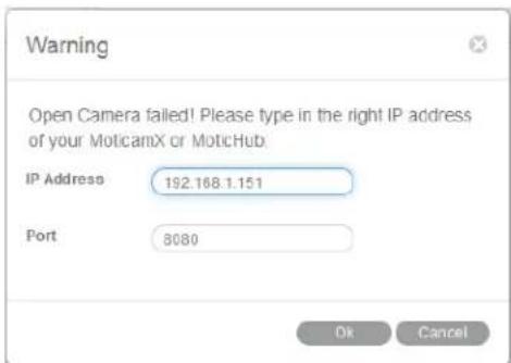
- Once you click OK, the image produced by your BTW tablet should appear.

TABLET SOFTWARE
This android tablet comes equipped will all the necessary software needed to start using your equipment out of the box. Since it is an android tablet, you will be able to connect to your office/school Wi-Fi network to access the internet and download additional applications. The primary application for accessing your camera is MotiConnect T.
MOTICONNECT-T OVERVIEW - HELP MENU
MotiConnect is a dedicated image processing Android app for Motic cameras, which includes image preview, capture, recording, editing and measuring functions. Please refer to the Application Help guide for a complete description of the MotiConnect Application.

HELP BUTTON

Help Menu - Opens a new window which provides a complete description of all the features available with the MotiConnect Application

CALIBRATION – (\*Optional – not necessary to use your microscope\*)
To prepare for the calibration process, please make sure you have the calibration slide. The calibration slide has four individual dark round circles. Each dark round circle corresponds with each objective on your microscope.
- The 1.5mm dot (150um – microns) with the 4X objective.
- The 0.6mm (600um – microns) with the 10X objective.
- The 0.15mm (150um – microns) with the 40x objective.
- The 0.07mm (70um – microns) with the 100X objective.
To begin the calibration process, place the calibration on the stage.
- First place your calibration slide on the stage, switch to the 4X objective, and move the slide over to the 1.5mm dot.
- With the dot centered on the tablet screen, select the calibration button, located on the bottom right hand side of the screen.
- You should have a bright green circle on the screen.
- Click the calibration button a second time.
- This time the calibration settings window will open.
- In the objective magnification window select the objective you captured the dot with. In this case the 4X objective.
- In the diameter window select the diameter of the dot you captured. In this case the 150um. Then click OK.
- The last window that will open is the Save Sign window. Since you capture this image with the 4X objective, it is best to enter this on this line.
- The objective line should default to the objective you are calibrating. In this case it should say 4X.
- The X and Y numbers on the next two lines should be near identical. Look at the first three numbers. As long as they are the same within one or two digits, you have a good calibration.
- Click Ok and you are done.
Calibration
To begin click on Create Calibration. Get out your Calibration Slide.

The software will capture the image from the preview mode and input the image into calibration mode.

natural_image
Circular dark green object on a light background, no visible text or symbolsNow put the Calibration slide on the stage of the microscope and focus the dot in the center of the screen. For 4x Objective, use the 1.5mm dot. For 10x Objective, use the 0.6mm dot. For the 40x Objective, use the 0.15mm dot. For the 100x Objective, use the 0.07mm dot.
After your dot is in focus, select "Create Calibration" then "Calibration" to add a new set of calibration parameters into the calibration table. You should have a bright green circle (shown below). If you don't have a bright green circle, the calibration failed. Make sure the slide is clean and the image has sufficient lighting.
If the calibration is successful, choose what objective you're using on the microscope under "Objective Magnification" then select the length of the diameter of the dot, then tap OK. A calibration is needed for each objective that will be used in measuring, so repeat the process if necessary.

Software will provide the um/Pixel X and um/Pixel Y based on the previous users provided information.

Users can save those parameters with user assigned own Sign Name. This new Sign Name will be saved in the calibration table for the future use.
Objective Magnification: If users change the objective magnification number, please ensure same magnification number is selected on the software. There is no need to re-calibrate the system.

TRANSFERING IMAGES TO YOUR COMPUTER
By default all your images are saved to the Micro SD card included with your M29TZ-SM99CL-BTW1 series microscope. This card is provided as a courtesy. If it is missing or lost, you will need to purchase a replacement. It is highly recommend that you purchase a Micro SD to Standard SD card adapter.

natural_image
Two black plastic electronic devices, one with a slot and the other a small slot (no text or symbols visible)This is simplest and easiest way to transfer images to your computer. Images are automatically captured as Jpeg images. If your computer/laptop does not come with an SD card slot, a SD card reader will need to be purchased as well. *Please note: 32GB Max*
MOTIC IMAGES 2.0 SOFTWARE
You can use your transfer images with the Motic Images 2.0 software included with microscope to annotate, save and file your images.
Full Help Menu
The full software manual for Motic Images is accessible within the software's main page.
• To begin, open the Motic Images Software.
- At the top of main screen find the menu tab labeled Help:

- Click on Help and then select the help option:

• This will open the Motic Images help file contents, containing the full help menu:
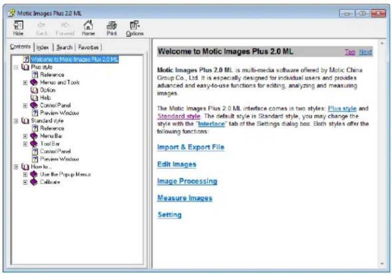
Motic Live 2.0 Live Imaging Module
If you are connecting your camera via WiFi to your laptop of WiFi enabled computer, you can use the Motic Images 2.0 software to view and capture your images.
Full Help Menu
- The full Live Imaging Module manual is accessible within the live Imaging main page.
• To begin, open the Motic Images Software. - At the top of main screen find the menu tab labeled File and click on Capture:
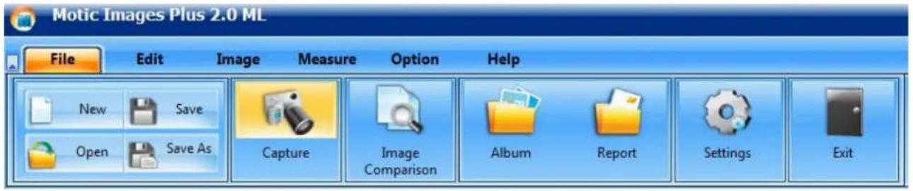
- Once the Motic Live Imaging Module has opened, click on Help:

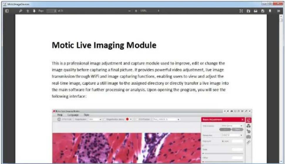
- This will open the Motic Live Imaging Module help file, containing the full help menu:

USING MOTIC IMAGES 3.0 SOFTWARE WITH THE BTW CAMERA
To connect the BTW camera (USB Mode) to a computer or laptop, you will need to download and install Motic Images 3.0, and purchase separately, an optional A-Male to Mini-B USB 2.0 cable (Available from any electronics website or retail store).
- Download and install Motic Images 3.0 from the Motic website.
- Switch your camera to USB mode.
- Plug the Mini-B end of your USB cable into the camera.
- Plug the flat A-Male end of your USB cable in the computer.
- The drivers for the camera should load automatically.
- Once the drivers have installed, open the Motic Image 3.0 Software.
- Click File, then scroll down to Capture.
- This will open the Motic Live Imaging Module.
- Your image should automatically display on the screen.
-
By default your live image is 3MP or 2048 x 1536 resolution.
12. -
The Motic Images 3.0 is constantly updating, so please check the Motic Website for updates. Registration is necessary. Use the DM number located on the sticker, on the software sleeve.
MOTIC IMAGES 3.0 SOFTWARE
The Motic Images 3.0 software, like the Motic Images 2.0 software will allow you to view, capture, annotate and save your images. For further assistance in using the Motic Images 3.0 software please refer to the Motic Help files. These files will help explain the functions of software. There are help files for both the main Motic Images software window, as well as the Motic Images Live Imaging window.
MOTIC IMAGES 3.0 HELP GUIDE
To access the Motic Images 3.0 help menu, click on Help, located at the top of the Motic Images software screen.

Once the Help window open you will find the help guide within.

Motic Live Imaging Module Help
To access the Motic Images Live Imaging help menu, click on Help located at the top left hand side of the screen.

Once the Help window open you will find the help guide within.
TROUBLESHOOTING
| PROBLEM | REASON FOR PROBLEM | SOLUTION |
| A light fails to operate. | Items not properly connectedSwitches not in proper position.Transmitted LED bulb burned out.Incidental LED bulb burned out. | Check all electrical connections from AC wall outlet to microscope input.Check switches and intensity controls.Replace LED bulbSend lamp assembly to National for bulb replacement. |
| Image does not remain in focus | Head of microscope drops from its own weight. | Adjust tension control. |
| Poor resolution (image not sharp) | Objective lenses dirty.Eyepiece lens dirty. | Clean objective lenses.Clean eyepiece lenses. |
| Spots in field of view. | Eyepiece lens dirty. | Clean eyepiece lenses. *** |
| ***Spots in field of view can also result from dirt on the inside of the eyepiece. It is recommended that you have service technician clean inside of lens. | ||
SWIFT OPTICAL INSTRUMENTS, INC. LIMITED LIFETIME WARRANTY
Please see our website, www.swiftoptical.com, for complete warranty details and exclusions.
Swift Optical Instruments, Inc. (877) 967-9438
www.swiftoptical.com
SWIFT


- Swift M29TZ-SM99CL-BTW1
- Microscope
- M29TZ-SM99CL
- UNPACKING
- ASSEMBLY
- OPERATION
- ILLUMINATION
- INTERPUPILLARY ADJUSTMENT
- FOCUSING
- ADAPTING C-MOUNT CAMERA to microscope (Trinocular Model Only)
- MAINTENANCE
- OPTICAL MAINTENANCE
- OPTIONAL BRACKET / CAMERA ASSEMBLY
- CONNECTING THE CAMERA TO BTW8 AND BTW10 TABLET
- POWER MANAGEMENT BTW 8 and BTW 10
- CONNECTING THE BTW TABLET TO EXISTING WIRELESS NETWORK
- Connecting your WiFi enabled device to the BTW tablet
- TABLET SOFTWARE
- MOTICONNECT-T OVERVIEW - HELP MENU
- HELP BUTTON
- CALIBRATION – (\*Optional – not necessary to use your microscope\*)
- Calibration
- TRANSFERING IMAGES TO YOUR COMPUTER
- MOTIC IMAGES 2.0 SOFTWARE
- Full Help Menu
- Motic Live 2.0 Live Imaging Module
- USING MOTIC IMAGES 3.0 SOFTWARE WITH THE BTW CAMERA
- MOTIC IMAGES 3.0 SOFTWARE
- MOTIC IMAGES 3.0 HELP GUIDE
- Motic Live Imaging Module Help
- SWIFT OPTICAL INSTRUMENTS, INC. LIMITED LIFETIME WARRANTY
Brand : Swift
Model : M29TZ-SM99CL-BTW1
Category : Microscope