
FO-DP4K-300-EMIX - Audio/video converter Avenview - Free user manual and instructions
Find the device manual for free FO-DP4K-300-EMIX Avenview in PDF.


| Product Type | 4K DisplayPort Extender over Fiber Optic (Transmitter + Receiver) |
| Model | FO-DP4K-300-EMIX (Set: FO-DP4K-300-EMIX-S + FO-DP4K-300-EMIX-R) |
| Dimensions (per unit) | 3.2 x 2.1 x 0.97 inches (81.3 x 53.3 x 24.6 mm) |
| Weight (per unit) | 1.5 lbs (680 g) |
| Power Supply | 5V DC, 2A (two adapters included) |
| Video Input (TX) | DisplayPort 1.2a |
| Video Output (TX) | Optical (SC connector) |
| Video Input (RX) | Optical (SC connector) |
| Video Output (RX) | DisplayPort 1.2a |
| Supported Resolutions | 4K (3840x2160 / 4096x2160) @ 60Hz, WQXGA 2560x1600 @ 60Hz, 1080p @ 60Hz, and others |
| Audio Support | LPCM 7.1, Dolby TrueHD, Dolby Digital Plus, DTS-HD Master Audio (32-192 kHz sample rate) |
| Maximum Distance | 300 m (1000 ft) over OM3 multimode fiber |
| Fiber Type | Single SC connector, multimode 50/125 μm OM3-rated |
| Bandwidth | 21.6 Gbps (HBR2), 5.4 Gbps per lane |
| MST Support | Yes (requires MST-capable source and monitors) |
| Compliance | DisplayPort 1.2a, DPCP, FCC Part 15, Class 2 Laser |
| Package Contents | Transmitter, Receiver, 2x Power Adapters, 2x DisplayPort Cables (3 ft), User Manual |
| Operating Temperature | 32°F to 104°F (0°C to 40°C) |
| Storage Temperature | -4°F to 140°F (-20°C to 60°C) |
| Humidity | 20% to 90% RH (non-condensing) |
| Safety Warnings | Class 2 laser product; do not stare into beam; avoid looking into fiber with lasers on |
| Cleaning Instructions | Use only specified fiber cleaning materials; do not reuse; avoid touching connector ends |
| Warranty | 3 years limited (parts and labor) |
Frequently Asked Questions - FO-DP4K-300-EMIX Avenview
User questions about FO-DP4K-300-EMIX Avenview
0 question about this device. Answer the ones you know or ask your own.
Ask a new question about this device
Download the instructions for your Audio/video converter in PDF format for free! Find your manual FO-DP4K-300-EMIX - Avenview and take your electronic device back in hand. On this page are published all the documents necessary for the use of your device. FO-DP4K-300-EMIX by Avenview.
USER MANUAL FO-DP4K-300-EMIX Avenview
4K DisplayPort Extender over Single SC Fiber Optic Cable


Product Application & Market Sectors

Corporate House

/orship

Military Resident


Education Industri


Medical Aviation

TABLE OF CONTENTS
I. GETTING STARTED .... I
I.1 IMPORTANT SAFEGUARDS
1.2 SAFETY INSTRUCTIONS ...... I
1.3 REGULATORY NOTICES FEDERAL COMMUNICATIONS COMMISSION (FCC) 2
2. INTRODUCTION....3
2.1 PACKAGE CONTENTS 4
3. APPLICATION DIAGRAM 5
4. PANEL DESCRIPTION....6
4.1 FRONT PANEL (Sender, FO-DP4K-300-EMIX-S)....6
4.2 REAR PANEL (Sender, FO-DP4K-300-EMIX-S)....6
4.3 FRONT PANEL (Receiver, FO-DP4K-300-EMIX-S)....7
4.4 REAR PANEL (Receiver, FO-DP4K-300-EMIX-S)....7
- INSTALLATION....8
5.1 Before Installation....9
5.2 Cable Specification....9
5.3 Installation Steps 10
- OPTICAL FIBER HAZARD 10
- GENERAL TROUBLESHOOTING ..... 11
7.1 Trouble Shooting depending on LED indicator status....I
- CAUTION......11
- DISPLAY PORT PIN ASSIGNMENT....12
- SPECIFICATIONS....13
I.1 IMPORTANT SAFEGUARDS
Please read all of these instructions carefully before you use the Fiber Optic cable. Save this manual for future reference.
What the warranty does not cover
- Any product, on which the serial number has been defaced, modified or removed.
• Damage, deterioration or malfunction resulting from: - Accident, misuse, neglect, fire, water, lightning, or other acts of nature, unauthorized product modification, or failure to follow instructions supplied with the product.
• Repair or attempted repair by anyone not authorized by us.
• Any damage of the product due to shipment. - Removal or installation of the product.
- Causes external to the product, such as electric power fluctuation or failure.
- Use of supplies or parts not meeting our specifications.
• Normal wear and tear.
• Any other causes which does not relate to a product defect. - Removal, installation, and set-up service charges.
1.2 SAFETY INSTRUCTIONS
The Avenview FO-DP4K-300-EMIX, Display port Extender over fiber Optic has been tested for conformity to safety regulations and requirements, and has been certified for international use. However, like all fibre optic products, the FO-DP4K-300-EMIX should be used with care. Read the following safety instructions to protect yourself from possible injury and to minimize the risk of damage to the unit.
On no account should you:
Look into a fiber while the system lasers are on;
Use unfiltered handheld magnifiers or focusing optics to inspect fiber connectors;
Connect a fiber to a fiberscope while the system lasers are on;
⚠️ Touch the end of the fiber connectors;
⚠️ Pull forcefully on the fiber cable;
⚠️ Reuse any specified fiber cleaning material more than once;
⚠️ Touch the clean area of a any specified fiber cleaning material;
Use alcohol around an open flame or spark - Alcohol is Very flammable;
Use alcohol or wet cleaning without a way to ensure that it does not leave residue on the polished connector;
⚠️ Dismantle the housing or modify the connector.
1.3
REGULATORY NOTICES FEDERAL COMMUNICATIONS COMMISSION (FCC)
This equipment has been tested and found to comply with part 15 of the FCC rules. These limits are designed to provide reasonable protection against harmful interference in a residential installation.
Any changes or modifications made to this equipment may void the user's authority to operate this equipment.
Warning symbols Description

LASER RADIATION
DO NOT STARE INTO BEAM
< I MILLIWATT LASER DIODE
CLASS 2 LASER PRODUCT
Risk levels increase. These lasers emit a visible beam, from 400 to 780 Nanometres (nm), with an upper power limit of 1 milliwatt. An example is a (mw) bar code scanner.
Momentary viewing is not hazardous, but extended viewing is. Laser protective eyewear is recommended for even momentary viewing and necessary for extended viewing

DO NOT TAMPER WITH THE FIBER CABLE; DOING SO WILL VOID THE WARRANTY AND CONTINUED USE OF THE PRODUCT.

natural_image
Blue circular icon with a white line drawing of a person wearing sunglasses (no text or symbols)THE VIDEO BOARDS ARE VERY SENSITIVE TO STATIC. PLEASE ENSURE IF RACK MOUNTED OR INSTALLED ON A SURFACE, IT SHOULD BE IN A GROUNDED ENVIROMENT.

natural_image
Blue circular icon with a white human figure holding an open book (no text or symbols)⚠ WARNING
Read & understand user guide before using this device.
Failure to follow the proper installation instructions could result in damage to the product and preventing expected results.
2. INTRODUCTION
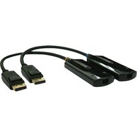
The Avenview FO-DP4K-300-EMIX-SET ULTRA HD Extender set over single SC optical fiber cable has been designed to extend 4K (3840x2160 or 4096 x 2160) @60Hz video and multi-channel audio formats to any 4K compatible monitor up to 300m.
Video Signals: 4k2k@60 (ultra HD), 3D and full HD 1080p@60 Hz.
Audio signals: Multi-channel audio formats (DTS-HD Master Audio, Dolby TrueHD).
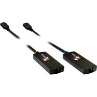
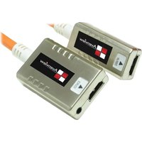
The FO-PD4K-300-EMIX-SET includes two (2) units: Sending unit (TX) FO-DP4K-300-EMIX-S and Receiving unit (RX) FO-DP4K-300-EMIX-R with one (1) FTP output port which allows the user to extend video and audio up to 300m (1000ft). The FO-DP4K-300-EMIX-SET input and output supports HBR2 cable assembly to handle upto 5.4Gbps/lane data rate.
The bonus features is the NEW box type design which can be easily installed into any environment, behind the monitor and rack mounted on a rack shelf. This features has been added to the unit to give the installer and user a complete solution with the new trends in rack mounted 4K sources streaming, network connected devices and new demand in Smart TV, ultra HD monitors and content.
- Input: Displayport 1.2a with 3D & ULTRAHD, 1080p,DPCP compliant;
- Bandwidth: from 21.6 Gbps;
- Video Data Rate: 5.4 Gbps;
- HD resolutions: up to ULTRA HD (3840x2160/4096 x 2160@60Hz) WQXGA 2560x1600@60Hz and 1080p (1920x1080@60Hz);
- Audio supported: IpCM 7.1CH, Dolby TrueHD, Dolby Digital plus and DTS-HD Master Audio;
- Audio transmission: (32-192kHz sample rate);
- MST (Multi-Stream) Supported;
- Distance: up to 300 meters over OM3 SC Fiber Optic cable.
NOTE:
- MST will be supported if the source device can support MST.
- A DisplayPort 1.2 MST-capable hub.
- A DisplayPort 1.2 MST-capable monitor(s).
- Displaying 4K Ultra HD resolution would require the standard Displayportl cable and display for accurate results.
2.1
PACKAGE CONTENTS
Before you start the installation of the converter, please check the package contents.
| 1 | (FO-DP4K-300-EMIX-SET)FO-DP4K-300-EMIX-S (TX) X1FO-DP4K-300-EMIX-R (RX) XI | 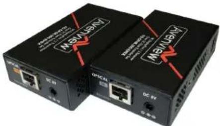 |
| 2 | POWER ADAPTER (5V/2A DC) X2 |  |
| 3 | DISPLAYPORT (COPPER CABLE - 3FT) X2 | 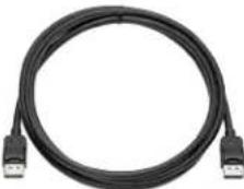 |
| 4 | USER 'S MANUAL X1 |  |
3.
APPLICATION DIAGRAM
| 1. LED LIGHT: Green light indicates an active connection. | 2. DISPLAYPORT IN: Displayport cord interface |
| 3. MODE: A. Default mode: video output level is set low to increase compatibility with equipment that is sensitive to jitter characteristicsB. Manual mode: video output level is set high to increase compatibility with equipment that is sensitive to EYE pattern characteristics | |
4.2 REAR PANEL (Sender, FO-DP4K-300-EMIX-S)

| 1. OPTICAL OUT: Connect SC type connector OM3 rated fiber For media streaming linking to Receiver | 2. 5V 2A Power Supply Jack: Connect provided power adapter for power supply |
4.3 FRONT PANEL (Receiver, FO-DP4K-300-EMIX-R)

| 1. LED Light: Green light indicates an active connection. | 2. Displayport OUT |
| 3. MODE: A. Default mode: enable link training and automatically attempts to match the monitor outputB. Manual mode: disable link training and pre-set the output signal characteristics (most compatible setting values is pre-set based on testing of different displays) | |
4.4 REAR PANEL (Receiver, FO-DP4K-300-EMIX-R)
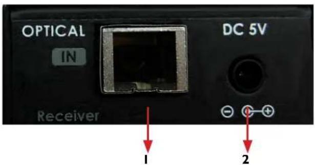
| 1. OPTICAL IN: Connect SC type connectorOM3 rated fiber For media streaminglinking to Sender | 2. 5V 2A Power Supply Jack |
5.
INSTALLATION
This product is composed of a Transmitter and a Receiver.
The Transmitter should be connected to the source (Computer's Displayport) and the Receiver should be connected the Displayport of the digital display device (Monitor). Avenview FO-DP4K-300-EMIX-SET Transmitter / Receiver is designed to be used with SC type standard optical cable (Multi-Mode optical fiber: 50/125, 62.5/125um)


Note: The Transmitter and the Receiver modules must be connected to the included power supplies for proper operation. Transmitter module must be powered on first.
5.1
BEFORE INSTALLATION
- Put the product in an even and stable location. If the product falls down or drops, it may cause an injury or malfunction.
- Don't place the product in too high temperature (over 50°C), too low temperature (under 0°C) or high humidity.
- Use the DC power adapter with correct specifications and supplied with the unit. If improper power supply is used the unit may malfunction and cause a fire.
• Do not twist or pull by force ends of the video cable. It can cause malfunction.
5.2
CABLE SPECIFICATIONS

natural_image
Close-up of a black USB connector with metallic casing (no text or symbols visible)To achieve best results with our FO-DP4K-300-EMIX-SET we recommend a high quality displayport cable 22-24 AWG cable with the below specifications to maintain signal integrity and distances.
NOTE: Misrepresentation with labels such as a DisplayPort 1.1 cable and DisplayPort 1.2 cable. A standard DisplayPort cable, including the label DisplayPort 1.1 cable, will work for any DisplayPort configuration including the new capabilities enabled by DisplayPort 1.2, including 4K and multi-stream capabilities. All standard DisplayPort cables support RBR, HBR (High Bit Rate), and HBR2 (High Bit Rate 2), which can support 4K at 60Hz, or up to four 1080p displays using multi-stream.
NOTE: For more reliable signal transmission we HIGHLY recommend using the MOLEX DP cable included in the package. This type of DisplayPort cable has been tested extensively and showed best compatibility with FO-DP4K-300-EMIX-SET
FEATURES:
- Any DisplayPort™ 1.2 Cable with latches and provides a secure, connection between your DisplayPort-equipped devices.
- Any DisplayPort™ cable that supports high resolutions of up to Ultra HD 4k x 2k (3840 x 2160/4096 x 2160) @ 60Hz with a maximum HBR2 bandwidth of 21.6 Gbps. Also supports Multi-Stream (MST) for daisy chaining multiple monitors and provides optional audio support.
5.3 Installation Steps:
I. Connect the Transmitter module to the Displayport source device.
2. Connect the Receiver module to the display.
3. Connect a single strand multi-mode SC terminated optic fiber (50/125um) from the Transmitter to the Receiver module.
4. Connect the included +5V DC power supply into the Receiver.
5. Blue LED indicator on the modules will be light up after all connections are completed.
Multimode Fiber
Multimode fibers with fiber a core diameter of 50 microns.

natural_image
Pure waveform diagram with red, green, and blue lines and an arrow (no text or symbols)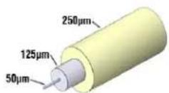





6. OPTICAL FIBER HAZARD

WARNING
Fibre Optic Cables
- Persons installing fiber optic products must take all necessary safety precautions, such as wearing protective clothing and goggles and observing warning signs.
- To ensure that the required personnel and equipment is properly installed, secure from unnecessary failure of the components or failure of the whole system, injury to one's self and in addition to legal responsibility; everyone is responsible for his own health
- Keep exposed optical fiber ends away from skin and eyes.
• The waste fragments should be treated with care and not picked up with bare hands, but rather with special gloves.
- Dispose of waste in a suitable container via an approved agency. Make sure that the quantity of optical fiber waste is minimized.
- Closures containing termination points for optical fiber cabling must be labeled with appropriate warning signs or clearly visible text.
- Make sure that the quantity of optical fiber waste is minimized. Closures containing termination points for optical fiber cabling must be labeled with appropriate warning signs or a clearly viewable text.
• There are four laser Classifications based on risk levels. Laser manufacturers are required to label their lasers accordingly.
7. GENERAL TROUBLESHOOTING
| Problem Possible Solutions | |
| NO IMAGE | Check if the pC power is onCheck if connection to the computer and the monitor are correct.Turn the pC power off and on again.please use DC adapter (5V, 2A) included in the package for transmitter and receiver. |
| LCD SCREEN DEFECTS APPEAR | This product supports up to WQXGA resolution.Check the maximum resolution range of the graphics card. |
7.1 Trouble Shooting depending on LED indicator status
| Problem Possible Solutions | |
| No display TX Solid / RX Blink | Check if monitor is powered onCheck if Display port source is selected on monitor input setting |
| No display TX Blink / RX Solid | Check if the pC and display are powered on and properly booted.Check if optic fiber is connected properly. |
| No display TX Blink / RX Blink | Please make sure that power supply is connected into TX and RX.Reset the system by de-plugging and re-plugging all conections |
8. CAUTION
- Do not put heavy object on top of the FO-DP4K-300-EMIX. It may cause product malfunction.
- Put the product on even and stable location. If the product falls down or dropped, it may get damaged.
- Keep away from high temperature (over 50^ C), low temperature (under 0^ C) or high humidity. It may cause a fire and injury by electrical shock.
- Use DC power adapter with correct specification. Otherwise it may cause fire.
- Use the multimode (50/125um) optical fiber.
- Do not view directly laser module of transmitter or the end of the other side of optical cable connected to transmitter with optical instrument.
- Do not twist or pull by force either ends of the optical cable. It can cause malfunction. Minimum bending diameter is 45mm
NOTE: Optical fiber cords of different types and specifications should not be mixed. Please note the color-coding of connectors for different fiber specs to make it easy to avoid confusion
9.
DISPLAYPORT PIN ASSIGNMENT
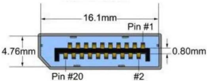
9.1 Transmitter
| PIN | SIGNAL ASSIGNMENT | PIN | SIGNAL ASSIGNMENT | PIN | SIGNAL ASSIGNMENT |
| 1 | Main Link Lane 0+ | 8 Ground 15 Auxiliary Channel + | |||
| 2 Ground 9 | Main Link Lane 2- | 16 Ground | |||
| 3 | Main Link Lane 0- | 10 | Main Link Lane 3+ | 17 Auxiliary Channe I - | |
| 4 | Main Link Lane + | 11 Ground 18 Hot plug Detect | |||
| 5 Ground 12 | Main Link Lane 3- | 19 Return | |||
| 6 | Main Link Lane 1- | 13 Configuration 1 20 | N/C | ||
| 7 | Main Link Lane 2+ | 14 Configuration 2 | |||
9.2 Receiver
| PIN | SIGNAL ASSIGNMENT | PIN | SIGNAL ASSIGNMENT | PIN | SIGNAL ASSIGNMENT |
| 1 | Main Link Lane 0+ | 8 | Ground | 15 | Auxiliary Channel + |
| 2 Ground | 9 | Main Link Lane 2- | 16 | Ground | |
| 3 | Main Link Lane 0- | 10 | Main Link Lane 3+ | 17 | Auxiliary Channel - |
| 4 | Main Link Lane 1+ | 11 Ground 18 Hot plug Detect | |||
| 5 Ground 12 | Main Link Lane 3- | 19 Return | |||
| 6 | Main Link Lane 1- | 13 Configuration 1 | 20 | N/C | |
| 7 | Main Link Lane 2+ | 14 Configuration 2 | |||
10. SPECIFICATIONS
| ITEM DESCRIPTION | ||
| MODEL FO-DP4K-300-EMIX-S FO-DP4K-300-EMIX-R | ||
| UNIT DESCRIPTION Displayport Extender Transmitter Displayport Extender Receiver | ||
| INPUT VIDEO PORT | DisplayPort | Optical |
| INPUT RESOLUTION | 4K (3840X2160 and 4096 x 2160) @ 60Hz WQXGA (2560x1600)@60Hz and 1080p (1920x1080)@60Hz, 2560x1440, 2560x1600, 2560x1080 | 4K (3840X2160 and 4096 x 2160) @ 60Hz WQXGA (2560x1600)@60Hz and 1080p (1920x1080)@60Hz, 2560x1440, 2560x1600, 256Ox1080 |
| OUTPUT VIDEO PORT | Optical | DisplayPort |
| OUTPUT RESOLUTION | Up to 4K (3840X2160 and 4096 x 2160) @ 60Hz, 2560x1440, 2560x1600, 2560x1080 | Up to 4K (3840X2160 and 4096 x 2160) @ 60Hz, 2560x1440, 2560x1600, 2560x1080 |
| COLOR SPACE | By pass all color spaces as RGB, YPbPr, YCbCr, etc.. | |
| CHROMA SUBSAMPLING | 4K 4:2:0 10bits, 4:2:2 10/12bits, 4:4:4 8bits@60Hz | |
| DIMESNIONS (L X W X H) | 3.2" X 2.1" X 0.97" | |
| POWER SUPPLY | 5V 2A | |
| WEIGHT | 1.5 lbs | |
OPTICAL
| OPTICAL SOURCE | 850nm VCSEI |
| O/E CONVERTER | PIN photo Diode |
| FIBER | Multi-Mode optical fiber (SC Type Connector) |
| FIBER TYPE | 50/125 μm Multi-mode glass fiber OM3 rated fiber |
ENVIRONMENTAL
| OPERATING TEMPERATURE | 32° ~ 104°F (0° to 40°C) |
| STORAGE TEMPERATURE -4° | ~ 140°F (-20° ~ 60°C) |
| RELATIVE HUMIDITY 20~90% | RH (no condensation) |
Notes
Notes
Avenview Warranty Certificate
AVENVIEW CORP. ("Avenview") warrants Avenview-branded product(s) contained in the original packaging against defects in materials and workmanship when used normally in accordance with Avenview's enclosed manual guidelines for a period of THREE (3) YEARS from the date of original retail purchase - Warranty Period. Avenview's published guidelines include but are not limited to information contained in technical specifications, user manuals and service communications.
LABOR: During the Warranty Period of THREE (3) YEARS, Avenview will repair or replace the product(s) at no cost using new or used parts equivalent to novel performance and reliability if the product(s) is determined to have abide by Avenview's published guidelines. Cost of Labor applicable to product(s) after Warranty Period. For labor costs, please contact support@avenview.com.
PARTS: During the Warranty Period of THREE (3) YEARS, Avenview will supply new or rebuilt replacements in exchange for defective parts of the product(s) at no cost if the product(s) is determined to have abide by Avenview's published guidelines. Cost of Parts applicable to product(s) after Warranty Period. For part(s) costs, please contact support@avenview.com.
To obtain Warranty: (a) proof of purchase in the form of a bill of sale or receipted invoice reflecting that the registered product(s) is within warranty period must be presented to obtain warranty service; (b) product(s) must be registered at time of purchase. Failure to do so will result in applicable parts and labor charges. Returning product(s) must be shipped in Avenview's original packaging or in packaging pertaining equal degree of protection to Avenview's. Both Avenview and purchaser are responsible for freight charges and brokerages when shipping the product(s) to the receiver.
NOT COVERED BY THIS WARRANTY
This warranty does not apply to any non-Avenview branded product(s); non-registered Avenview product(s). This warranty does not apply: (a) to cosmetic damage, including but not limited to scratches, dents and broken cords; (b) to damage caused by use with another product; (c) to damage caused by accident, abuse, misuse, liquid contact, fire, earthquake or other external cause; (d) to damage caused by operating the Avenview product(s) outside Avenview's manuals or guidelines; (e) to damage caused by service performed by anyone who is not a representative of Avenview or an Avenview authorized personnel; (f) to defects caused by normal wear and tear or otherwise due to the normal aging of the Avenview product(s), or (g) if any serial number has been removed or defaced from the Avenview product(s).
AVENVIEW IS NOT LIABLE FOR DIRECT, SPECIAL, INCIDENTAL OR CONSEQUENTIAL DAMAGES RESULTING FROM ANY BREACH OF WARRANTY OR CONDITION, OR UNDER ANY OTHER LEGAL THEORY, INCLUDING BUT NOT LIMITED TO LOSS OF USE; LOSS OF REVENUE; LOSS OF ACTUAL OR ANTICIPATED PROFITS (INCLUDING LOSS OF PROFITS ON CONTRACTS); LOSS OF THE USE OF MONEY; LOSS OF ANTICIPATED SAVINGS; LOSS OF BUSINESS; LOSS OF OPPORTUNITY; LOSS OF GOODWILL; LOSS OF REPUTATION; LOSS OF, DAMAGE TO, COMPROMISE OR CORRUPTION OF DATA; OR ANY INDIRECT OR CONSEQUENTIAL LOSS OR DAMAGE REPAIR OR REPLACEMENT AS PROVIDED UNDER THIS WARRANTY IS THE EXCLUSIVE REMEDY OF THE CONSUMER.
Some states do not allow the inclusion or limitation of incidental or consequential damages, or allow limitations on duration implements of the Warranty Period; therefore the above limitations or exclusions may not be applicable to you. This warranty gives you specific legal rights, and you may have other rights which vary from state to state.

275 Woodward Avenue, Kenmore, NY 14217 1.866.508.0269

Avenview
Control Your Video...
TECHNICAL SUPPORT
CONTACT US

Phone: I (866) 508 0269

Email: support@avenview.com

natural_image
Illustration of a globe with headphones and a headset, symbolizing global communication (no text or symbols present)USA Head Office Avenview Corp. 275 Woodward Avenue Kenmore, NY 14217
USA Head Office
Office Avenview Corp.
275 Woodward Avenue
Kenmore, NY14217
Phone: +1.716.218.4100
Fax: +1.866.387-8764
Email: info@avenview.com
Canada Sales
Avenview
151 Esna Park Drive, Units 11 & 12
Markham, Ontario, L3R3B1
Phone: 1.905.907.0525
Fax: 1.866.387.8764
Email: info@avenview.com
Avenview Europe
Avenview Europe
Demkaweg II
3555 HW Utrecht
Netherlands
Phone: +31(0)85 2100 613
Unit 8, 6/f., Kwai Cheong Centre,
50 Kwai Cheong Road,
Kwai Chung, N.T.
Hong kong
Phone: 852.3575.9585
Email: wenxi@avenview.com
Disclaimer
While every precaution has been taken in the preparation of this document, Avenview Inc. assumes no liability with respect to the operation or use of Avenview hardware, software or other products and documentation described herein, for any act or omission of Avenview concerning such products or this documentation, for any interruption of service, loss or interruption of business, loss of anticipatory profits, or for punitive, incidental or consequential damages in connection with the furnishing, performance, or use of the Avenview hardware, software, or other products and documentation provided herein.
Avenview Inc. reserves the right to make changes without further notice to a product or system described herein to improve reliability, function or design. With respect to Avenview products which this document relates, Avenview disclaims all express or implied warranties regarding such products, including but not limited to, the implied warranties of merchantability, fitness for a particular purpose, and non-infringement.

- 4K DisplayPort Extender over Single SC Fiber Optic Cable
- Product Application & Market Sectors
- TABLE OF CONTENTS
- I.1 IMPORTANT SAFEGUARDS
- What the warranty does not cover
- SAFETY INSTRUCTIONS
- 1.3
- REGULATORY NOTICES FEDERAL COMMUNICATIONS COMMISSION (FCC)
- Warning symbols Description
- ⚠ WARNING
- INTRODUCTION
- NOTE:
- 2.1
- PACKAGE CONTENTS
- APPLICATION DIAGRAM
- REAR PANEL (Sender, FO-DP4K-300-EMIX-S)
- FRONT PANEL (Receiver, FO-DP4K-300-EMIX-R)
- REAR PANEL (Receiver, FO-DP4K-300-EMIX-R)
- 5.
- INSTALLATION
- 5.1
- BEFORE INSTALLATION
- 5.2
- CABLE SPECIFICATIONS
- FEATURES:
- Installation Steps:
- OPTICAL FIBER HAZARD
- WARNING
- Fibre Optic Cables
- GENERAL TROUBLESHOOTING
- Trouble Shooting depending on LED indicator status
- CAUTION
- DISPLAYPORT PIN ASSIGNMENT
- Transmitter
- Receiver
- SPECIFICATIONS
- Avenview Warranty Certificate
- NOT COVERED BY THIS WARRANTY
- Avenview
- TECHNICAL SUPPORT
- CONTACT US
- USA Head Office
- Canada Sales
- Avenview Europe
- Disclaimer
Brand : Avenview
Model : FO-DP4K-300-EMIX
Category : Audio/video converter