
ESO 97 S - Temperature Controller KATHREIN - Free user manual and instructions
Find the device manual for free ESO 97 S KATHREIN in PDF.


| Product Type | Temperature Controller for Reflector and Feed System Support Heating |
| Brand | Kathrein |
| Model | ESO 97 S |
| Dimensions (H x W x D) | 254 x 180 x 111 mm |
| Weight | 900 g |
| Housing Material | Polycarbonate |
| Protection Class | IP66 |
| Operating Voltage | 208-230 V~, ±10%, 50/60 Hz |
| Switching Capacity | 16 A / 230 V; 80 A (20 ms) |
| Alarm Contact Rating | 8 A / 230 V |
| Measuring Input | Pt100 temperature sensor (3-wire or 2-wire) |
| Display Range / Resolution | -50 to +400°C / 1K |
| Permissible Ambient Temperature | -30 to +60°C |
| Recommended Installation Temperature | +5 to +20 °C |
| Type of Control | Electronic two-point controller with adjustable temperature threshold |
| Setting Range (Default) | -5 to +15°C (adjustable via parameters P13/P14) |
| Scope of Supply | Terminal box with installation kit, 1 m tensioning strap, 4 x M16 blind plugs, Pt100 sensor (5 m), cable ties, M32 cable gland, earthing clamp, earthing cable, instructions |
| Installation | Mast mounting using tensioning strap; required earth-leakage circuit breaker (0.03 A) |
| Maintenance | Regular functional check; cooler spray recommended for ambient temperature above +5°C; largely maintenance-free after installation |
| Safety Features | Alarm relay for over/under temperature, sensor errors; code protection for parameters |
| Error Indication | Display shows error codes: E01, E02, E03, C00 |
| Compliance | Installation and connection by qualified specialist personnel only |
Frequently Asked Questions - ESO 97 S KATHREIN
User questions about ESO 97 S KATHREIN
0 question about this device. Answer the ones you know or ask your own.
Ask a new question about this device
Download the instructions for your Temperature Controller in PDF format for free! Find your manual ESO 97 S - KATHREIN and take your electronic device back in hand. On this page are published all the documents necessary for the use of your device. ESO 97 S by KATHREIN.
USER MANUAL ESO 97 S KATHREIN
Temperature Control for the Reflector and Feed System Support Heating
About These Instructions
This document is part of the product. These instructions describe how to install and connect the ESO 97 S temperature control.
▶ Do not install or use the device until you have read and understood this document.
▶ Keep this document for reference throughout the service life of the device. Pass this document on to any new owner or user.
The most up-to-date version of this document can be found at www.kathrein-ds.com
Features
ESO 97 S is a temperature control for the reflector heatings ESO 90/120/124/180 H and the feed system support heatings ESO 126 and ESO 129.
■ Electronic two-point controller with adjustable temperature threshold
■ The heating is automatically switched on when the outdoor temperature falls below the set value
■ With tensioning strap for mast mounting
Scope of Supply
■ 1 x terminal box with installation kit
■ 1 m tensioning strap for terminal box
■ 4 x M16 blind plugs
■ 1 x Pt100 temperature sensor, ∅ 5 x 50 mm, length 5 m
■ 10 x cable ties, 208 mm

natural_image
Exterior view of a white electronic device with multiple ports and connectors, accompanied by a close-up of connected cables and connectors (no visible text or symbols)■ 5 x cable ties, 360 mm
■ 1 x cable gland M32 x 1.5, plastic
■ 1 x earthing clamp
■ 0.5 m earthing cable 4 mm
■ Instructions for use
Transport and Storage
▶ If possible, transport and store the temperature control in its original packaging.
▶ Protect the temperature control against moisture and mechanical damage.
Intended Use
Do not use the ESO 97 S for purposes other than those listed in these instructions. Any other use will invalidate the warranty or guarantee.
In particular, never
■ modify any of its components or
■ fit any components other than those expressly intended by the manufacturer for use with the ESO 97 S.
The following circumstances will result in the loss of warranty and liability claims towards the manufacturer:
■ Improper installation
■ Use of non-specified mounting materials which cannot guarantee the mechanical safety
■ Impermissible use
■ Structural changes or interference with the components and mounting accessories in the kit, which may compromise the mechanical, electrical and functional safety
■ Use of cleaners containing solvents, such as acetone, nitro-cellulose thinners, petrol, etc.
- Failure to observe the installation and safety instructions in these instructions

ESO 97 S is recommended for controlling the refl ector heatings ESO 90/120/124/180 H. Any other use will invalidate the warranty or guarantee.
Installation and connection may only be carried out by qualified specialist personnel!
To prevent hazards during installation and operation, the instructions and notes must be strictly adhered to. Proper installation and connection are prerequisites for conformity with the relevant standards.
Safety Notes

WARNING
Risk of severe injuries during installation due to falling from or through the roof or due to falling parts! Make sure that:
▶ the connected devices are disconnected from the mains supply
▶ the person carrying out the installation or repair does not suffer from vertigo and can move around safely on the roof or installation site
▶ the person carrying out the installation or repair is wearing sturdy non-slip shoes
▶ the person carrying out the installation or repair has a secure position to stand and hold on whilst working
▶ the roof and the climbing equipment (e.g. ladder) are dry and non-slip
▶ the roof can withstand the weight of the person carrying out the repairs
▶ there is nobody underneath the antenna during installation/dismantling

DANGER
Danger to life from electric shock when touching electrical installations!
The correct execution of the installation and the electrical connections are important for safety.
Carefully observe the specified installation conditions and steps.
Modifications to the electrical installation may only be carried out by a qualified electrician. Do not make any unauthorised changes.
Functional Description
The built-in electronic temperature controller serves as an air thermostat for recording the ambient temperature. It is fitted with cable glands and clamps for the power supply.
Function:
If the actual value (P01) falls below the target value (P10 minus hysteresis P11), the load relay switches on the heating. The integrated alarm relay provides error messages via a changeover contact in case of over-/under-temperature, sensor interruption or sensor short circuit. In case of sensor errors, the control relay switches the heating element off or on, depending on the controller configuration.
The heating is switched off if the sensor is disconnected or in case of a short circuit.

Operation
Operation is very easy. After switching on, the display shows the type number of the unit (C-2) and after about 3 seconds the measured actual value. If you press the "P" key briefly, the display shows "Set" and then the target value. After 5 seconds, the display automatically returns to "Set". Press the "P" key for about 3 seconds to get to the parameter list "P10". Press the "P" key for a further 3 seconds to display "dC" for degrees Celsius or "dF" for degrees Fahrenheit.
Call up and change parameters
To open the parameter list, press "P" for about 3 seconds until "P10" appears.
- Press "P" for 3 seconds: Parameter number is displayed
■ Press "▲/▼": Select the parameter - Press "P" for 3 seconds: Parameter is displayed
■ Press "▲/▼": Change the parameter value - Press "P" for 3 seconds: New value was saved, back to parameter number
- By keeping the “▲/▼” keys pressed, the values are progressing automatically. Press until “P1” or T>1 minute is displayed and exit the input mode
Protection against unauthorised access
The control target value can be set as desired, unless limited by P13/14. All other parameters are protected by a code.
If a code is required, the display shows "C00". Use the arrow keys to set the required code number (C42) and confirm with "P".
If no key is pressed for approx. 1 minute, the code is requested again.
Auto-scrolling
By keeping the “▲/▼” keys pressed, the values are progressing automatically.
Error messages
If an error occurs, the display shows an error code. Sensor errors are displayed with a delay of about 20 seconds.
Error codes
E01 Sensor short circuit or temperature < -60°C
E02 Sensor disconnection or temperature > 410°C
E03 Temperature sensor, 3rd wire is missing or R ≥ 10 Ω
C00 Protected parameters, code is required
Device type
After switching on, the display shows the type number of the unit (C-2) and after about 3 seconds the measured actual value.
Parameters and their meaning
U = Ambient temperature device 1
P01 Actual value at temperature sensor (display only)
P10 Control target value, acts on relay 1, range P13 ... P14, [U +5°C]
P11 Switching hysteresis of P10, range 2 ... 10K, [U 2K]
P12 Minimum downtime (relay K1); range 0 ... 30 minutes, [5 minutes]
P13 Largest selectable target value, range P14 ... +390°C, [U +15°C]
P14 Smallest selectable target value, range -50°C ... P13, [U -5°C]
P20 Sensor type
0 = Pt100, 3-wire, °C (resolution 1K)
[1] = Pt100, 2-wire, °C (resolution 1K)
2 = Pt100, 3-wire, °F (resolution 2°F)
3 = Pt100, 2-wire, °F (resolution 2°F)
P21 Sensor correction -30 ... +10K, [0]
P30 Over-temperature alarm, P31 ... 400°C, [60°C]
P31 Under-temperature alarm, -60 ... P30, [-60°C]
P32 Alarm delay during operation, 0 ... 99 minutes, [0 minutes]
P33 Alarm delay after switching on, 0 ... 500 minutes, [0 minutes]
P34 Relay mode (load relay K1 and signalling relay K2)
0 = Relay K2 (active) picks up in the case of sensor error, load relay K1 drops out in the case of sensor error
[1] = Relay K2 (passive) drops out in the case of sensor error, load relay K1 drops out in the case of sensor error
2 = K2 operates as release relay, load relay K1 drops out in the case of sensor error
3 = Relay K2 (active) picks up in the case of sensor error, load relay K1 picks up in the case of sensor error
4 = Relay K2 (passive) drops out in the case of sensor error, load relay K1 picks up in the case of sensor error
5 = K2 operates as release relay, load relay K1 picks up in the case of sensor error

P34 = 3, P34 = 4 and P34 = 5 is only permitted for anti-freezing applications and for use with self-regulating heating cables.
The values in square brackets [...] are the default settings.
Release relay mode
Relay K2 switches to this operating mode (P34 = 2 and P34 = 5) independently of P32 and P33 as soon as the actual value is within P30 and P31.
Alarm relay mode
(P34 = 0 or 1): If the actual temperature is below P31 when the device is started, P33 is used once as an alarm delay in order to give the system more time. In normal operation, P32 is used as an alarm delay.


Installation in outdoor temperature control mode
The controller is mounted on the antenna mast as high above the ground as possible using a tensioning strap. Recommended setting when used as an outdoor temperature control for reflector heaters: +3 to +5°C
According to the guidelines for outdoor installations, an earth-leakage circuit breaker with a nominal residual current of 0.03 A must be connected upstream.
Technical Data
Mechanical data
Housing material: Polycarbonate
Dimensions: 254 x 180 x 111 mm
Weight: 900 g
Cable entries: 3 x M12, 5 x M16, 1 x M32/M25
Permissible ambient temperature: -30 to +60°C
Recommended installation temperature: +5 to +20 °C
Electrical data
Operational voltage: 208 to 230 V\~, ±10%, 50/60 Hz
Switching capacity: 16 A / 230 V; 80 A (20 ms)
Alarm contact: 8 A / 230 V
Measuring input: Pt100 temperature sensor
Switch-on temperature U: +5°C (default setting P10)
Maximum setting range U: -5 to +15°C (default setting P13/P14)
Display range / resolution: -50 to +400°C / 1K
Protection class: IP66
Type of control: Two-point controller
Installation and Connection
Required tools and equipment
■ Side cutters
- Pointed pliers
■ Pipe wrench
■ Flat-bladed screwdriver
■ Cooler spray for performance check
■ 2 x SW13 open-end spanner

Safe operation of the control unit requires that all components are properly installed and put into operation in accordance with the warnings given in these installation instructions.
Before starting the installation, check with the material list whether all parts are included.
Installing the temperature control
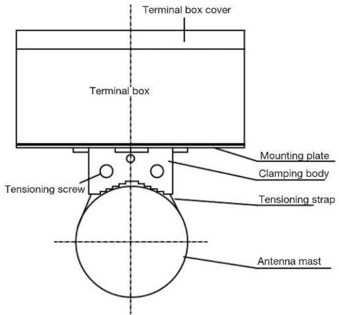
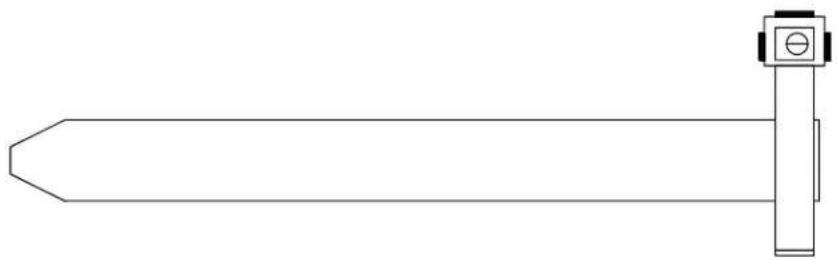
- The control unit / terminal box with the pre-assembled installation kit is fastened to the antenna mast as high above the ground as possible using the tensioning strap. The exact installation height depends on the local conditions.
- Place the steel strap around the unslotted screw. The length of the short end of the steel strap must be approx. one third of the mast tube circumference.
- Cut the long end of the steel strap to the installation length, and cut to a point at the front. The installation length is determined by the mast tube circumference.
- Insert the pointed end of the steel strap into the slot-headed screw and turn the screw head anti-clockwise. The steel strap now wraps around the tensioning screw and the universal jubilee clip is tightened. Tighten the nut to prevent the clip from coming loose. The universal jubilee clip can be released at any time and reused.

Electrical connection
- Run the connection cable from the heating mats and feed system support heating along the antenna support to the ESO 97 S terminal box and fasten it with cable ties. In case the heating mat is fitted with a temperature sensor, this sensor cannot be used with the ESO 97 S. This sensor is used with the ESO 97 SL to determine the current heating temperature. ESO 97 SL enables energy-saving operation by additionally setting an upper switch-off temperature for the heating mat.
- Insert the cable from below through the M16 glands (heating mats, feed system support heating) into the control unit / terminal box.
- Insert the mains cable from below through the M32/M25 gland into the control unit / terminal box.

Test the heating for contact resistance and insulation resistance before connecting the cables in the control unit.
These tests should be repeated after replacing a defective heating element. For more information, refer to the operating instructions of the corresponding reflector heater.
- The cables are connected according to the „Wiring Diagram“ on page 8.

For electrical connection, observe the voltage specified on the type plate. Non-observance can lead to destruction of the heating system by overheating or fire!

Connecting the earthing clamp
The earthing clamp is attached to the antenna mast near the terminal box as follows:
- Place the tensioning strap around the mast. Make sure that the tensioning strap is tight around the antenna mast.
- Pull the V2A strap through the clamp.
- Tighten the V2A strap with the tensioning screw.
- Connect the earthing cable to the earthing clamp.
- Insert the earthing cable through an M12 gland into the terminal box (see illustration „Alarm relay mode“ on page 4).
- Connect the earthing cable to the earthing terminal.
⇒ This ensures earthing of the entire electrical system.
natural_image
Simple line drawing of a sword with a vertical post and handle (no text or symbols)Maintenance
Check the correct attachment and function of the control device at regular intervals (a cooler spray is recommended for ambient temperatures above +5°C).
Apart from these regular checks, the ESO 97 S is largely maintenance-free after installation.
Repair and Replacement
autronic electronic-service GmbH
Hauptstraße 2a
Electronic equipment
Electronic equipment is not domestic waste – in accordance with directive 2012/19/EC OF THE EUROPEAN PARLIAMENT AND THE COUNCIL dated 04th July 2012 concerning used electrical and electronic appliances, it must be disposed of properly. At the end of its service life, take this unit to a designated public collection point for disposal.
WiringDiagram

- Temperature Control for the Reflector and Feed System Support Heating
- About These Instructions
- Features
- Scope of Supply
- Transport and Storage
- Intended Use
- Safety Notes
- WARNING
- DANGER
- Functional Description
- Function:
- Operation
- Call up and change parameters
- Protection against unauthorised access
- Auto-scrolling
- Error messages
- Error codes
- Device type
- Parameters and their meaning
- P34 Relay mode (load relay K1 and signalling relay K2)
- Release relay mode
- Alarm relay mode
- Installation in outdoor temperature control mode
- Technical Data
- Mechanical data
- Electrical data
- Installation and Connection
- Required tools and equipment
- Installing the temperature control
- Electrical connection
- Connecting the earthing clamp
- Maintenance
- Repair and Replacement
- Electronic equipment
Brand : KATHREIN
Model : ESO 97 S
Category : Temperature Controller