
99-2006 - Car kit Metra - Free user manual and instructions
Find the device manual for free 99-2006 Metra in PDF.


| Product Type | Car Installation Kit |
| Brand | Metra |
| Model | 99-2006 |
| Compatible Vehicles | Select GM trucks and SUVs (e.g., Chevrolet Silverado, GMC Sierra 2003-2006) |
| Material | High-grade ABS plastic |
| Color | Black |
| DIN Size | Single DIN with storage pocket |
| Dimensions | Approximately 7 x 2 x 6 inches |
| Weight | 0.5 lbs |
| Mounting Type | Screw-in |
| Includes | Radio housing, storage pocket, wire harness, mounting brackets, screws |
| Installation Time | About 30 minutes |
| Tools Required | Trim removal tools, screwdrivers, wire strippers, crimpers |
| Features | Factory-like fit, easy installation, no vehicle modification required |
| Warranty | 1 year limited warranty |
| Support | Metra Online Support and installation guides |
| Maintenance | Wipe with a dry cloth; avoid harsh chemicals |
| Safety | Disconnect vehicle battery before installation; use proper tools |
| Repairability | Non-repairable; replace unit if damaged |
Frequently Asked Questions - 99-2006 Metra
User questions about 99-2006 Metra
0 question about this device. Answer the ones you know or ask your own.
Ask a new question about this device
Download the instructions for your Car kit in PDF format for free! Find your manual 99-2006 - Metra and take your electronic device back in hand. On this page are published all the documents necessary for the use of your device. 99-2006 by Metra.
USER MANUAL 99-2006 Metra
INSTALLATION INSTRUCTIONS FOR PART 99-2006
APPLICATIONS
Cadillac CTS 2003-2007
Cadillac SRX 2004-2006
99-2006/ 99-2006G
KIT FEATURES
• DIN Radio Provision with Pocket
• ISO Mount Radio Provision with Pocket
• Double DIN Radio Provision
- Stacked DIN Head Units Provision
- Painted To Match Factory Dash
99-2006 = BLACK
99-2006G = GRAY

natural_image
Interior view of a car dashboard with air filters and steering wheel (no visible text or symbols)KIT COMPONENTS
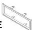
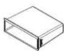
A) Radio Housing • B) DDIN Brackets • C) DDIN Trim Plate • D) ISO Brackets • E) Trim Plate • F) (8) Phillips screws • (G) Pocket
A

natural_image
Technical line drawing of a car front panel with mounting brackets (no text or symbols)B


[Non-Text]

E
G
F

TOOLS REQUIRED:
Phillips Screwdriver • Small Flat Blade Screwdriver • Socket Wrench


1-800-221-0932

www.metraonline.com
© COPYRIGHT 2004-2008 METRA ELECTRONICS CORPORATION
TABLE OF CONTENTS
Dash Disassembly 1
Kit Assembly 2,3,4
Final Assembly 5
CADILLAC CTS 2003-2007
CADILLAC SRX 2004-2006
1 Disconnect the negative battery terminal to prevent an accidental short circuit.
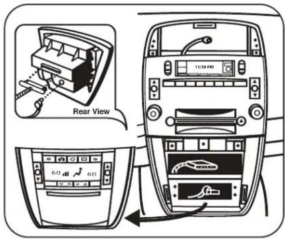
2 Unclip and remove the center air vent assembly above the radio. (Figure A)
3 Open ashtray and remove (1) Phillips head screw from inside ashtray.
4 Unclip and remove the a/c control/ashtray assembly below the radio. (Figure B)
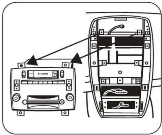
5 Remove (4) 10 MM screws securing the radio to the dash. (Figure C, D)
A

B
D

C
DIN RADIO PROVISION WITH POCKET
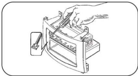
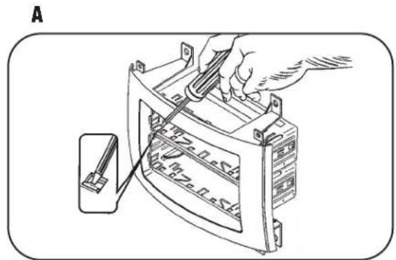
1 Slide the DIN cage into the Radio Housing and secure by bending the metal locking tabs down. (Figure A)
2 Slide the aftermarket head unit into the cage and secure. (Figure B)
3 Slide the supplied pocket into the unused opening.
A
natural_image
Line drawing of a hand using a tool to adjust or install a device with a spring scale (no text or symbols)B

natural_image
Technical line drawing of a mechanical device casing with mounting brackets and control panel (no text or symbols)ISO MOUNT RADIO PROVISION WITH POCKET
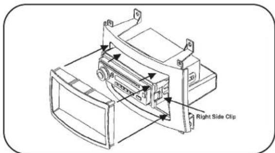
1 Mount the ISO Brackets to the head unit with the screws supplied with the unit. (Figure A)
2 Slide the head unit into the radio opening until the side clips engage. (Figure B)
3 Snap the Trim plate into the Radio Housing. (Figure B)
4 Slide the supplied pocket into the unused opening.
A

natural_image
Line drawing of a hand using a screwdriver to adjust or install a device on a computer case (no text or symbols visible)B
DOUBLE DIN RADIO PROVISION
1 Remove the center bar from the 99-2006 radio housing. (Figure A)
2 Attach the corresponding bracket to the DDIN head unit. (Figure B)
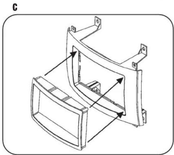
3 Insert the DDIN trim plate into the radio housing. (Figure C)
4 Position the bracket/radio assembly to the back of the radio housing and secure with the (8) Phillips screws provided. (Figure D)

natural_image
Line drawing of a hand holding a metal bracket with mounting holes (no text or symbols)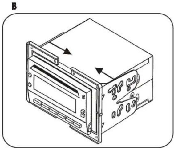
natural_image
Technical line drawing of a device casing with mounting holes and internal components (no text or symbols)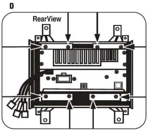
natural_image
Technical line drawing of a mechanical bracket component (no text or symbols)STACKED DIN HEAD UNITS PROVISION
1 Slide the DIN cages into the Radio Housing and secure by bending the metal locking tabs outward. (Figure A)
2 Slide the aftermarket head units into the cages and secure. (Figure B)

natural_image
Technical line drawing of a device casing with mounting brackets and control panel (no text or symbols)FINAL ASSEMBLY
1 Locate the factory wiring harness in the dash and make the connection as shown. Metra recommends using the proper mating adapter and making the connections as shown. (Isolate and individually tape off the ends of any unused wires to prevent electrical short circuit.)
2 Re-connect the negative battery terminal and test the unit for proper operation.
3 Reassemble radio and dash assemblies in reverse order of disassembly.
FINAL WIRING CONNECTIONS
Make wiring connections using the ElA color code chart shown below and the instructions included with the head unit. Metra recommends making connections as shown below; Strip, Splice, Solder, Tape. Isolate and individually tape off ends of any unused wires to prevent electrical short circuit.

METRA / EIA WIRING CODE
12V Ignition / Acc ... Red
12V Batt / Memory .. Yellow
Ground .... Black*
Power Antenna ..... Blue
Amp Turn-On ..... Blue / White
Amp Ground ..... Black / White
Illumination.....Orange
Dimmer ..... Orange / White
Right Rear (+).....Violet
Right Rear (-) ..... Violet / Black
Left Rear (+).... Green
Left Rear (-) ..... Green / Black
*NOTE: When Black a wire is not present, ground radio to vehicle chassis.
All colors may not be present on all leads due to manufacturer's specifications.
INST992006
- INSTALLATION INSTRUCTIONS FOR PART 99-2006
- APPLICATIONS
- Cadillac CTS 2003-2007
- Cadillac SRX 2004-2006
- 99-2006/ 99-2006G
- KIT FEATURES
- KIT COMPONENTS
- TOOLS REQUIRED:
- TABLE OF CONTENTS
- DIN RADIO PROVISION WITH POCKET
- ISO MOUNT RADIO PROVISION WITH POCKET
- DOUBLE DIN RADIO PROVISION
- STACKED DIN HEAD UNITS PROVISION
- FINAL ASSEMBLY
- FINAL WIRING CONNECTIONS
- METRA / EIA WIRING CODE
Brand : Metra
Model : 99-2006
Category : Car kit