
RIO1S - Unknown Bogen - Free user manual and instructions
Find the device manual for free RIO1S Bogen in PDF.


| Product Type | Relay / Input / Output Transformer-Balanced Module |
| Input Type | Transformer-isolated, balanced line-level |
| Input Impedance | Selectable: 600 Ω or 10 kΩ via jumper |
| Output Type | Transformer-isolated, balanced line-level; 8 Ω speaker output |
| Output Power | 750 mW into 8 Ω |
| Controls | Input gain control, output level control |
| Relay Contacts | Configurable as Normally Open (N.O.) or Normally Closed (N.C.) |
| Relay Priority Levels | Selectable: 2, 3, 4 (Level 1 not applicable) |
| Muting | External control of priority muting; input can be muted by higher priority modules |
| Output Gating | Continuous or gated based on priority level (jumper selectable) |
| Bus Assignment (Input) | Assignable to A bus, B bus, or both (jumper selectable) |
| Bus Assignment (Output) | Assignable to A bus, B bus, or MIX bus (jumper selectable) |
| Connections | Screw terminal strips, RJ11 connector (output and N.O. relay contact) |
| Installation | Slides into module bay, secured with two screws; power must be off |
| Power Supply | Powered by main unit through module bay |
| Compatibility | Bogen M-Class and Power Vector systems |
| Jumper Selections | Impedance, input muting, bus assignment, relay priority, output gating, relay contacts |
| Wiring | Supports balanced and unbalanced input/output wiring |
| Speaker Output | 8 Ω, 750 mW maximum; connect + and - correctly |
| Safety Warning | Turn off power before installation or jumper changes |
Frequently Asked Questions - RIO1S Bogen
User questions about RIO1S Bogen
0 question about this device. Answer the ones you know or ask your own.
Ask a new question about this device
Download the instructions for your Unknown in PDF format for free! Find your manual RIO1S - Bogen and take your electronic device back in hand. On this page are published all the documents necessary for the use of your device. RIO1S by Bogen.
USER MANUAL RIO1S Bogen
RIO1S
Relay / Input / Output Transformer-Balanced Module
Features
- Transformer-isolated, balanced line-level input
- 600-ohm or 10k-ohm jumper-selectable input impedance
- Transformer-isolated, balanced line-level output
• 8-ohm, 750mW output - Input and output level controls
- Relay responds to selectable priority level
• External control of priority muting
• N.O. or N.C. relay contacts - Input can be muted from higher priority modules, with signal fade back
- Output can activate with relay priority level
- Screw terminal strips
• RJ11 connection with line output and dedicated N.O. relay contact
Module Installation
- Turn off all power to the unit.
- Make all necessary jumper selections.
- Position module in front of any desired module bay opening, making sure that the module is right-side up.
- Slide module onto card guide rails. Make sure that both the top and bottom guides are engaged.
- Push the module into the bay until the faceplate contacts the unit's chassis.
- Use the two screws included to secure the module to the unit.
WARNING:
Turn off power to unit and make all jumper selections before installing module in unit.
Note:
This module may include a break-away tab as pictured below. If present, remove this tab to install module in input module bays.

Controls and Connectors
Gain (Input)
Provides control over the level of input signal.
Signal Output
Transformer-balanced, low-impedance (8-ohm) line-level output.
Mute + / Mute -
Provides access to the mute bus priority system. Allows external equipment to directly control the internal mute buses.

Level (Output)
Provides control over the level of output signal.
RJ11Connection
This connector contains the output signal and a set of normally open relay contacts. It acts similar to telephone systems' page ports and facilitates interfacing to paging systems with override capabilities (PCM2000, ZPM3).
Input Signal
Transformer-balanced, line-level input.
Prioritized Relay Output
Provides access to the priority controlled relay contacts. Can be jumper configured as normally open (N.O.) or normally closed (N.C.).
Jumper Selections
Impedance Selector
This module can be set for two different input impedances. When connecting to a 600-ohm source, it is desirable to have a 600-ohm matching input impedance. For typical source equipment, use 10k-ohm setting.
Input Muting
This module's input can remain continuously active or be muted by other modules. When muting is enabled, the input is permanently set to the lowest priority level. When disabled, the input will not respond to any priority signal and will remain active continuously.
Input Bus Assignment
This module can be set to operate so that the input signal can be sent to the main unit's A bus, B bus, or both buses. Bus selection pertains to M-Class use only. Power Vector has only one bus. Set jumpers to Both for Power Vector use.
External Mute Priority Level
Determines what priority level the system will see when looking at the external control. Selecting Level 1 will result in the external device becoming the highest priority mute and silencing all lower priority modules. Likewise for all other lower settings except for priority Level 4, which is not applicable since modules with this level can only respond to mute signals. Priority Level 4 modules cannot send mute signals.

flowchart
graph TD
    A["INPUT IMPEDANCE SELECTOR"] --> B["600-ohm J19 10K J19"]
    C["INPUT MUTING"] --> D["Enabled Disabled J3 J3"]
    E["INPUT BUS ASSIGNMENT"] --> F["J14 J14 J14"]
    G["EXTERNAL MUTE PRIORITY LEVEL"] --> H["J25 J26 (HI) J25 J26 (LO)"]
    I["Input Bus Assignment"] --> J["A B Both J14 J14 J14"]
    K["Input Bus Assignment"] --> L["J23 J22 J14"]
    M["Input Bus Assignment"] --> N["J23 J22 J14"]
    O["Input Bus Assignment"] --> P["J23 J22 J14"]
    Q["Input Bus Assignment"] --> R["J23 J22 J14"]
    S["Input Bus Assignment"] --> T["J23 J22 J14"]
    U["Input Bus Assignment"] --> V["J23 J22 J14"]
    W["Input Bus Assignment"] --> X["J23 J22 J14"]
    Y["Input Bus Assignment"] --> Z["J23 J22 J14"]
Jumper Selections, cont.
Relay Priority Level
The relay setting determines what priority level and above will cause the relay to energize. Since this module's relay must receive a mute signal from a higher priority module to change states, it is only possible to use the three lower priority levels (2, 3, 4). Priority Level 1 (highest) is not applicable.
Output Gating
The output signal can be available continuously or available only when the relay priority level setting has been met or exceeded. When set to ACTIVE, it provides continuous signal output. When set to GATE, it provides output based on priority level.
Relay Contacts
This module's screw terminal relay contacts can be set for normally open (N.O.) or normally closed (N.C.) operation.
Output Bus Assignment
The output signal can be taken from the module's A bus, B bus, or the unit's MIX bus. On some Bogen amplifier products, the A and B buses may be tied together.

flowchart
graph TD
    A["OUTPUT BUS ASSIGNMENT"] --> B["OUTPUT GATING"]
    B --> C["RELAY PRIORITY LEVEL"]
    A --> D["RELAY CONTACTS"]
    D --> E["N.O. J24"]
    D --> F["N.C. J24"]
    A --> G["MIX BUS B J23 J22 BUS J23 J22 BUS A J23 J22"]
    A --> H["J19"]
    A --> I["J3"]
    A --> J["J24"]
    B --> K["GATE J4 ACTIVE J4"]
    B --> L["J4"]
    B --> M["J20"]
    B --> N["J21"]
    B --> O["J25"]
    B --> P["J26"]
    C --> Q["2 3 4"]
    C --> R["HI"] (J20 J21) (J20 J21) (J20 J21) (J20 J21) (LO)]
Input Wiring
Balanced Connection
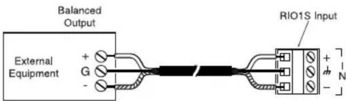
Use this wiring when the external equipment supplies a balanced, 3-wire signal.
Connect the shield wire of the external signal to the ground terminal of the external equipment and to the ground terminal of the RIO1S. If the "+" signal lead can be identified, connect it to the plus "+" terminal of the RIO1S. If the external equipment polarity cannot be identified, connect either of the hot leads to the plus "+" terminal. Connect the remaining lead to the minus "-" terminal of the RIO1S.
Note: If polarity of the output signal versus the input signal is important, it may be necessary to reverse input lead connections.
Unbalanced Connection
When the external device provides only an unbalanced connection (signal and ground), the RIO1S module should be wired with the "-" terminal shorted to ground. The unbalanced signal's shield wire is connected to the input module's ground and the signal hot wire is connected to the "+" terminal. Since unbalanced connections do not provide the same amount of noise immunity that a balanced connection does, the connection distances should be made as short as possible.

Output Wiring
Balanced Connection
Use this wiring when the external equipment requires a balanced, 3-wire signal.
Connect the shield wire to the ground terminal of the external equipment and to the ground terminal of the RIO1S. If the "+" signal lead from the external equipment can be identified, connect it to the plus "+" terminal of the RIO1S. If the external equipment polarity cannot be identified, connect either of the hot leads to the plus "+" terminal. Connect the remaining lead to the minus "-" terminal of the RIO1S.
Note: If polarity of the output signal versus the input signal is important, it may be necessary to reverse input lead connections.

Unbalanced Connection
When the external device provides only an unbalanced connection (signal and ground), the RIO1S module should be wired with the "-" terminal shorted to ground. The unbalanced signal's shield wire is connected to the input module's ground and the signal hot wire is connected to the "+" terminal. Since unbalanced connections do not provide the same amount of noise immunity that a balanced connection does, the connection distances should be made as short as possible.

Speaker Output Wiring
8ΩOutput
The RIO1S output is capable of driving an 8Ω speaker load. Available power is up to 750mW. When connecting a speaker, be sure to connect the module's "+" and "-" to the speakers "+" and "-", respectively.

Block Diagram

flowchart
graph TD
    A["OUTPUT"] --> B["XFMR"]
    B --> C["GAIN"]
    C --> D["OUTPUT GATE"]
    D --> E["OUTPUT BUSES"]
    E --> F["BUS ASSIGNMENT"]
    F --> G["Active Gate"]
    G --> H["PRIORITY MUTE BUSES"]
    H --> I["MUTE HIGH"]
    H --> J["MUTE MED."]
    H --> K["MUTE LOW"]
    L["PAGE PORT OUT"] --> M["(RJ11)"]
    N["RELAY CONTACT"] --> O["N.O."]
    P["MUTE CONTROL"] --> Q["N.C."]
    R["INPUT"] --> S["XFMR"]
    S --> T["GAIN"]
    T --> U["MUTING"]
    U --> V["INPUT BUSES"]
    V --> W["BUS ASSIGNMENT"]
    X["600-ohm"] --> Y["10k-ohm"]
    Z["Relay"] --> AA["Relay"]
    AB["Out (-) 2"] --> AC["Relay"]
    AD["Out (+) 5"] --> AE["Relay"]
    AF["Out (-) 1"] --> AG["Relay"]
BOGEN®
COMMUNICATIONS, INC.
www.bogen.com
- RIO1S
- Relay / Input / Output Transformer-Balanced Module
- Features
- Module Installation
- WARNING:
- Note:
- Controls and Connectors
- Gain (Input)
- Signal Output
- Mute + / Mute -
- Level (Output)
- RJ11Connection
- Input Signal
- Prioritized Relay Output
- Jumper Selections
- Impedance Selector
- Input Muting
- Input Bus Assignment
- External Mute Priority Level
- Jumper Selections, cont.
- Relay Priority Level
- Output Gating
- Relay Contacts
- Output Bus Assignment
- Input Wiring
- Balanced Connection
- Unbalanced Connection
- Output Wiring
- Speaker Output Wiring
- 8ΩOutput
- Block Diagram
- BOGEN®
- COMMUNICATIONS, INC.
Brand : Bogen
Model : RIO1S
Category : Unknown