
ZCK18307XA - Frying Pan ZANUSSI - Free user manual and instructions
Find the device manual for free ZCK18307XA ZANUSSI in PDF.


| Product Type | Built-in Gas Hob |
| Brand | Zanussi |
| Model | ZCK18307XA |
| Dimensions (Width x Depth x Height) | 600 x 510 x 44 mm (cut-out: 560 x 480 mm) |
| Weight | Approx. 8 kg |
| Number of Burners | 4 |
| Burner Types | 1 Triple Crown, 1 Semi-rapid, 1 Rapid, 1 Auxiliary |
| Gas Type | Natural Gas (G20) / LPG (G30) convertible |
| Ignition | Automatic electronic ignition |
| Safety Features | Flame failure safety device on all burners |
| Control Knobs | Front panel rotary knobs |
| Surface Material | Stainless steel with enamel pan supports |
| Cleaning | Removable pan supports and burner caps for easy cleaning |
| Electrical Supply | 230-240 V, 50-60 Hz |
| Gas Connection | Rear gas connection, 1/2 inch BSP thread |
| Energy Efficiency Class | A |
| Installation | Built-in (requires professional installation) |
| Spare Parts Availability | Thermocouples, burner caps, knobs, and igniters available through service centers |
| Warranty | 2 years (subject to terms) |
Frequently Asked Questions - ZCK18307XA ZANUSSI
User questions about ZCK18307XA ZANUSSI
0 question about this device. Answer the ones you know or ask your own.
Ask a new question about this device
Download the instructions for your Frying Pan in PDF format for free! Find your manual ZCK18307XA - ZANUSSI and take your electronic device back in hand. On this page are published all the documents necessary for the use of your device. ZCK18307XA by ZANUSSI.
USER MANUAL ZCK18307XA ZANUSSI
User & Installation Manual
Cooker
USER MANUAL
ZCK18307XA
ZCK98307XA
ZANUSSI
Contents
Safety information 2
Product description 4
Operation 6
What to do if... 15
Installation 15
Technical information 22
Environment concerns 24
Subject to change without notice
Safety information
You have purchased one of our products for which we thank you. We are confident that this new appliance, modern, functional and practical, made with top quality materials, will meet all your demands. This new appliance is easy to use but before installing and using it, it is important to read this handbook through carefully. It provides information for a safe installation, use and maintenance. Keep this handbook in a safe place for future reference.
The manufacturer reserves the right to make all the modifications to its products that it deems necessary or useful, also in your interests, without prejudicing its essential functional and safety characteristics. The manufacturer cannot be held responsible for any inaccuracies due to printing or transcription errors that may be found in this handbook.
N.B.: the pictures shown in the figures in this handbook are purely indicative.
- The installation, adjustments, conversions and maintenance operations listed in section “Installation” must only be carried out by authorised personnel.
- The installation of all-gas and combi appliances must comply with the standards in force.
- The appliance must only be used for its original purpose, that is, cooking for domestic use. Any other use is considered improper and, as such, dangerous.
- The manufacturer cannot be held responsible for any damage to persons or property resulting from an incorrect installation, maintenance or use of the appliance.
- Once the packaging has been removed from the outer surfaces and the various inner parts, thoroughly check that the appliance is in perfect condition. If you have
any doubts do not use the appliance and call in an authorised person.
- The packaging materials used (cardboard, plastic bags, polystyrene foam, nails, etc.) must not be left within easy reach of children because they are a potential hazard source. All packaging materials used are environmentally-friendly and recyclable.
- The electrical safety of this appliance is only guaranteed if it is correctly connected to a suitable earth system, as prescribed by the electrical safety standards. The manufacturer disclaims all responsibility if these instructions are not followed. Should you have any doubts, seek the assistance of an authorised person.
- Before connecting the appliance ensure that the rating plate data corresponds to that of the gas and electricity supply (see section “Technical information”).
- NOT FOR USE IN MARINE CRAFT, CARAVANS OR MOBILE HOMES UNLESS EACH BURNER IS FITTED WITH A FLAME SAFEGUARD.
- DO NOT MODIFY THIS APPLIANCE
- DOMESTIC USE ONLY

Warning! The appliance and its accessible parts become hot during use. Care should be taken to avoid touching heating element. Children less than 8 years of age shall be kept away unless continuously supervised.

Hot surface
- The oven door glass and the accessible parts will become hot when in use. To avoid burns and scalds young children should be kept away.
- Do not use this appliance as a space heater.
-
Do not touch any electrical appliance if hands or feet are wet or damp.
-
Do not use the appliance bare footed.
- Do not pull the power lead to take the plug out of the socket.
- Do not leave the appliance outside under the sun, rain, etc.
- Young children should be supervised to ensure that they not play with the appliance.
- This appliance can be used by children aged from 8 years and above and persons with reduced physical, sensory or mental capabilities or lack of experience and knolegde if they have been given supervision or instruction concerning use of the appliance in a safe way and understand the hazards involved. Children shall not play with the appliance. Cleaning and user maintenance shall not be made by children with out supervision.
Warning! In order to prevent accidental tipping of the appliance, for example by a child climbing over the open oven door, or too high weights are leant on the open oven door, two chains must be screwed on the back on the cooker and fixed to the wall with hooks. Ensure the chains are taut. Please refer to instructions for installation.
- Before cooking for the first time, ensure the oven is empty and its door closed, heat the oven at maximum temperature for two hours. This will allow the protective coating on the interior of the oven to be burnt off and dissipate the associated smells. Ensure adequate ventilation in the kitchen whilst burning off and don't be alarmed by a little bit of smoke during this process.
- When you insert the oven shelf, be sure that the rear stopper of the oven rack must be positioned upwards.
- Unattended cooking on a hob with fat or oil can be dangerous and may result in fire.
- Never try to extinguish a fire with water, but switch off the appliance and then cover flame e.g. with a lide or a fire blanket.
- Danger of fire: Do not store items on the cooking surfaces
- Do not use harsh abrasive cleaners or sharp metal scrapers to clean the oven glass door since they can scratch the surface, which may result in shattering of the glass.
- Never use sponges or abrasive products, and solvents to remove stains or adhesives on the painted or stainless steel surfaces.
- Switch off the oven before removing the fan guard for cleaning. Replace the guard after cleaning in accordance with the instructions.
- The oven can be equipped with temperature probe. Only use the temperature probe recommended for this oven by our Service Centre.
- Remove any spillage from the lid before opening.
- The appliance is not intended to be operated by means of an external timer or separate remote-control system.
- Ensure that the appliance is switched off before replacing the lamp to avoid the possibility of electric shock.
The cookers can be equipped with a small compartment under the oven that can be used for storing things Remember that the surfaces become hot, it is strictly forbidden to place inflammable materials inside.
- Do not use a steam cleaner to clean a hob, oven or range.
- The appliance is to be placed directly on the floor and shall not be mounted on a base.
- If the appliance is fitted with a glass lid, this can shatter when heated. Turn off all the burners or disconnect all the plates, and allow them to cool before closing the lid (fig.3)
- Avoid using the oven as a larder or as a saucepan cupboard when you are not using it for cooking: if the oven is turned on accidentally it could cause damage and accidents.
- If you are using an electrical socket near the appliance, make sure that the cables are not touching the cooker and are far enough away from all hot parts.
- When you have finished using the appliance check that all the controls are in the off or closed position, checking that the "0" of the knob corresponds to the "■" symbol serigraphed on the front panel.
- Switch off the electrical supply before you start cleaning or servicing the appliance.
- In the case of a failure or malfunction, turn the appliance off and switch off the electrical supply and do not tamper with it. All repairs or adjustments must be carried
out with maximum care and the proper attention of an authorised person.
- For this reason we recommend you call our Service Centre.

Warning! Be careful when you cut the plastic strip to avoid damaging the cable
The installation must be carried out by a suitably qualified person, in accordance with the current version of the following.
UK Regulations and Safety Standards or their
European Norm Replacements.
Building Regulations (issued by the Department of the Environment).
Building Standards (issued by the Scottish Development Department).
IEE Wiring Regulations.
Electricity At Work Regulations.
Gas Safety (Installation and Use) (Amendment)
Regulations.
Product description
Presentation
The cooker can be fitted with a gas hob. Each knob on the front panel has a diagram printed above it showing to which burner it refers.
The combination of the different sized burners or heating elements offers the possibility of various types of cooking.
Our cookers have two ovens with different volumes.
The left oven cavity, which is the biggest, features of oven natural or forced convection with electric grill and makes all types of cooking possible. The right oven cavity, which is the smallest, features of oven natural convection with electric grill.
To guarantee the customer a good and safe use of the appliance, the combined and alla electrical cookers, have equipped with a safety temperature device, which automatically turns on in case the main thermostat fails to work. In such an event, the electricity is interrupted temporarily: do not attempt to repair it yourself but turn the appliance off and contact your nearest Assistance Centre.
The oven walls are fitted with various runners (fig. 1) on which the following accessories can be placed (fig.2).
Supply and quantities vary from model to model:
- oven shelf
- drip tray or drip pan

fig.1

natural_image
Isometric illustration of two rectangular trays with slatted bases, no text or symbols presentfig.2
Description of hob controls
Gas burner knob (fig.3)
By rotating the knob in an anticlockwise direction, the following symbols appear:
| ● | = Closed position |
| ☆○ | = “Full on” position |
| ○ | = “Reduced rate” position |

natural_image
Diagram of a mechanical or optical component with labeled parts (no readable text or symbols)fig.3
Right oven commutator/thermostat knob (fig.4)
By rotating the knob in an anticlockwise direction, the following functions appear:
| ● | = Closed position |
 | = Oven light on, which stays on for all function |
| from 50 to Max | = Oven temperatures |
 | = Grill heating element on |

fig. 4
Left oven -Multifunction selector knob (fig.5)
By turning the knob to the right or to the left you will find the following symbols:
| 0 = Oven off | |
| = Oven light on, which stays on for all functions | |
| = Fan motor | |
| = Top and bottom heating elements on | |
| = Top and bottom heating elements and fan on | |
| = Bottom heating element and fan on | |
| = Rear heating element and fan on | |
| = Grill heating element on | |
| = Grill heating element and fan on | |

By turning the oven knob clockwise we will find the different oven temperature values (from 50°C to Maxi).
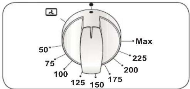
fig. 6
Red warning light
If present, when lit, it indicates that an electric component is inserted
Yellow warning light
When lit it indicates that the oven or the grill is in use. During cooking time the led turns off each time the temperature set is reached. It is therefore common that the led/yellow light turns on and off several times according to re-heating process.
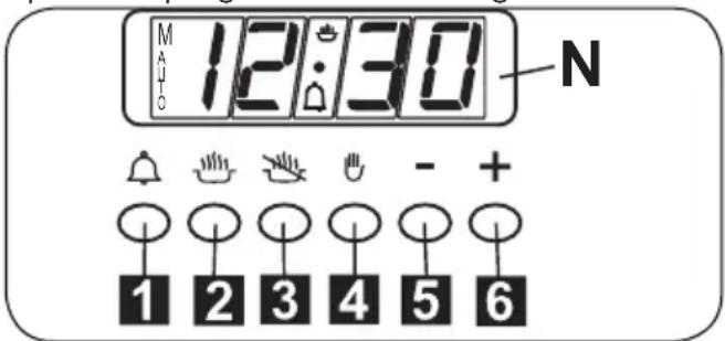
Electronic programmer
The programmer can select the following functions:
1 Minutecounter
2 Cookingtime/Clock
3 End of cooking/Clock
4 Manual operation mode
5 Setting time backwards
6 Setting time forward
The digital display (N) always shows the time and can display cooking and end of cooking time or the minute counter time by pressing
the corresponding push button.
N.B.: At the end of each setting session (except for the minute counter) the programmer turns the oven off. Check when next using the oven, if the programmer is not going to be used, that the latter is set on manual operation (see the instructions given further on).
Setting the time (from 0.01 to 24.00 = hh, mm)
After connecting to the electricity mains or subsequent to a power cut, AUTO and "0.00" will both flash simultaneously on the display. Press push buttons 2 and 3 simultaneously and start setting the current time by pressing push button 5 or 6.
Once set the AUTO symbol will turn off and the 🔒 symbol, for manual operation, will turn on.
Minute counter (from 0.01 to 0.59 = hh, mm)
Press push button 1 and select cooking time with push button 5 or 6. The 🔒 symbol turns on. At the end of the set time the buzzer will go off and the 🔒 symbol turns off.
Semi-automatic operation (with cooking time from 0.01 to 23.59 = hh, mm)
By pressing push button 2 and setting the length of cooking time with push button 5 or 6, the AUTO and symbols will light up and stay on all the time. At the end of the set time the 🔒 symbol will turn off, the AUTO symbol will flash and the buzzer will go off.
Semi-automatic operation (with end of cooking time from 0.01 to 23.59 = hh, mm)
By pressing push button 3 and setting the end of cooking time with push button 6, the AUTO and symbols will turn on and stay on all the time. At the end of the set time the symbol will turn off, the AUTO symbol will flash and the buzzer will go off.
Automatic operation (with the start of cooking time delayed)
First programme cooking time (both the AUTO and 📁 symbol will turn on) and then the end of cooking time (the 📁 symbol will turn off) as described previously. The 📁 symbol will turn on again when baking in the oven starts. At the end of cooking time the
symbol will turn off, the AUTO symbol will flash and the buzzer will go off.
Manual operation
Manual operation is only possible when the automatic programming has finished or after having cancelled it by pressing push button 4. The AUTO symbol disappears and the
symbol turns on.Manual operation is only possible when the automatic programming has finished or after having cancelled it by pressing push button 4. The AUTO symbol disappears and the symbol turns on.
Buzzer
The buzzer will go off at the end of a programme or at the end of the minute counter function and lasts about 7 minutes. The buzzer can be stopped by pressing one of the function push buttons. Programme start and control. The programme starts after setting. The programme set can be controlled at any time by pressing the corresponding push button.
Correcting/cancelling the programme setting
An automatic function programming error will occur if the time shown on the clock is between the cooking start time and cooking end time. This error will be signalled immediately by a buzzer and the AUTO symbol will flash. A setting error can be corrected by altering the duration or end of cooking time. Any programme that has been set can be corrected at any time by pressing the corresponding programming key and then key 5 or 6. To cancel a programme, correct the time set bringing it to a value of "0.00". If functioning time is cancelled the end of functioning is cancelled too and vice versa. The oven turns off automatically and the AUTO symbol flashes. Press key 4 to set the programmer on manual operation. The right time cannot be corrected when the automatic operation programme is working.
Hob: general notes on safety
When a gas cooker is being used it produces heat and humidity in the room where it is installed. For this reason the room must be well ventilated, keeping the natural ventilation openings free and switching on the mechanical aeration system (suction hood or electric fan, see the “Ventilation” and “Location and aeration” paragraphs. If the cooker is used for a long time additional aeration may be necessary, for instance, opening a window, or a more effective aeration by increasing the power of the mechanical system if there is one.
Automatic electric ignition of burner
Press and turn the knob corresponding to the burner you wish to use counterclockwise to the "Full on" position.
Automatically the ignition spark shoots
Once lit, keep the knob pressed for about 1 seconds. Matches can be used to light the burners in a blackout.
Optimum use of the burners
To get the maximum yield with the minimum consumption of gas it is handy to keep the following points in mind:
- Once the burner has been lit, adjust the flame according to your needs.
- Use an appropriately sized pan for each burner (see the table below and fig. 2).
- When the content of the pan start to boil, turn the knob down to "Reduced rate position" (small flame).
- Always put a lid on the pan.


natural_image
Simple line drawing of two cooking pots with crossed x-bracing, one on a stove and the other on a pot (no text or symbols)fig.2
| Burners ∅ pan cm | |
| Ultrarapid 22÷24 | |
| Rapid 20÷22 | |
| Semi-rapid 16÷18 | |
| Auxiliary 12÷14 | |
Oven: general notes on safety
■ Always grip the centre of the oven door when opening. Do not practice excessive pressures on the door when it is open.
- Do not worry if condensation forms on the door and on the internal walls of the oven during cooking. This does not compromise its efficiency.
- When opening the oven door, be very careful of scalding vapours.
- Use oven gloves to insert or remove containers from the oven.
- Use containers that will resist the temperatures indicated on the thermostat knob.
- For good results during cooking, we strongly recommend not to cover the base of the oven or the grill with aluminium foil or other materials.
- When grilling always put a little water in the grill pan.
- The water prevents the grease from burning and from giving off bad smells and smoke. Add more water during grilling to compensate for evaporation.
After using the appliance ensure that all the controls are in the off position.
How to use the multifunction oven
Left oven cavity

Defrosting at room temperature
Turn the selector knob to the symbol and place the food you want to defrost inside the oven.
The length of time required depends on the quantity and type of food.
Selecting this function will only activate the fan. Mild air circulation around frozen food will slowly defrost it.
It is particularly suitable for fruit and cakes.

Traditional cooking
Turn the selector knob to the symbol and adjust the thermostat knob to the desired temperature.
If pre-heating is recommended wait till the thermostat yellow warning light turns off before placing foods inside the oven. This option turns on both bottom and top heating units, evenly distributing heat on your foods.
This type of cooking is ideal for all kind of foods (meats, fish, bread, pizzas, cakes..).

Combined traditional + fan
cooking
Turn the selector knob to the symbol and adjust the thermostat knob) to the desired temperature. If pre-heating is recommended wait till the thermostat yellow warning light turns off before placing foods inside the oven. This option turns on both bottom and top heating units, and heat is distributed by fan ventilation.
This combination is suitable for rapid cooking and allows for the use of more plates positioned on the different levels of the oven.

Defrosting + warm up by hot air
Turn the selector knob to the symbol and adjust the thermostat knob to the desired temperature, then place the food inside the oven. Selecting this function will activate the bottom heating unit and its heat is distributed by the fan. This function is particularly recommended to defrost and warm up ready-made meals.

Fan forced cooking
Turn the selector knob to the symbol and adjust the thermostat knob to the desired temperature, then place your food inside the oven.
If pre-heating is recommended wait till the thermostat yellow warning light turns off before placing foods inside oven. This function activates the rear heating unit and the fan distributes the heat produced. This combination allows for a fast and even cooking of several different foods placed on the diverse levels of the oven.

Conventional grill cooking
Turn the selector knob to the symbol and adjust the thermostat knob to the desired temperature.
Selecting this function the top central heating element turns on and heat is distributed directly on food surface.
Apart from grilling, this function is ideal to add a golden roast to your recipes or to toast bread slices.
The grill function automatically activates the spit if present.
When you use the grill, do not forget to place the drip pan beneath it to collect any sauce dripping, as suggested in the "Useful cooking tips" section.

Fan grill cooking
Turn the selector knob to the symbol and adjust the thermostat knob to the desired temperature.
Selecting this function the top central heating element turns on and heat is distributed by the fan. This procedure mitigates the direct heat on food surface and uses milder temperatures. It is therefore recommended for an even golden and crispy finish touch, ideal for whole fish and poultry.
When you use the grill, do not forget to place the drip pan beneath it to collect any sauce dripping, as suggested in the "Useful cooking tips" section.
How to use the conventional oven
Right oven cavity

Traditional cookinh
Turn the commutator/thermostat knob on the temperature required. If pre-heating is recommended wait till the thermostat yellow warning light turns off before placing foods inside the oven. Both the bottom and top
heating elements are turned on, distributing heat to the food from the top and bottom. This type of baking is ideal for all types of food (meat, fish, bread, pizza, cakes..).

Grill cooking
Turn the commutator/thermostat knob on the symbol.
The top heating element is turned on and it distributes heat directly onto the food.
Besides grilling, it can be used to obtain a golden finish onto cooked foods or to toast your bread slices.
The grill function automatically activates the eventual spit (if present). When you use the grill, do not forget to place the drip pan beneath the spit to collect any sauce dripping, as suggested in the “COOKING TIPS” section.
Useful cooking tips
Cakes and bread:
- Heat the oven for at least 15 minutes before you start cooking bread or cakes.
- Do not open the door during baking because the cold air would stop the yeast from rising.
- When the cake is cooked turn the oven off and leave it in for about 10 minutes.
- Do not use the enamelled oven tray or drip pan, supplied with the oven, to cook cakes in.
- How do you know when the cake is cooked? About 5 minutes before the end of cooking time, put a cake tester or skewer in the highest part of the cake. If it comes out clean the cake is cooked.
- And if the cake sinks? The next time use less liquids or lower the temperature 10^ .
- If the cake is too dry: Make some tiny holes with a toothpick and pour some drops of fruit juice or spirits on it. The next time, increase the temperature 10^ and set a shorter cooking time.
- If the cake is too dark on top: the next time put the cake on a lower shelf, cook it at a lower temperature and longer.
-
If the top of the cake is burnt: cut off the burnt layer and cover with sugar or decorate it with cream, jam, confectioner's cream, etc..
-
If the cake is too dark underneath: the next time place it on a higher shelf and cook it at a lower temperature.
- If the cake or bread is cooked nicely outside but is still uncooked inside: the next time use less liquids, cook at a lower temperature and longer.
- If the cake will not come out of the tin: slide a knife around the edges, place a damp cloth over the cake and turn the tin upside down. The next time grease the tin well and sprinkle it with flour or bread crumbs.
- If the biscuits will not come away from the baking tray: put the tray back in the oven for a while and lift the biscuits up before they cool. The next time use a sheet of baking parchment to prevent this happening again.
Meat:
- If, when cooking meat, the time needed is more than 40 minutes, turn the oven off 10 minutes before the end of cooking time to exploit the residual heat (energy saving).
- Your roast will be juicier if cooked in a closed pan; it will be crispier if cooked without a lid.
- Normally white meat, poultry and fish need medium temperatures (less than 200°C).
- To cook “rare” red meats, high temperatures (over 200°C) and short cooking times are needed.
- For a tasty roast, lard and spice the meat.
- If your roast is tough: the next time leave the meat to ripen longer.
- If your roast is too dark on top or underneath: the next time put it on a higher or lower shelf, lower the temperature and cook longer.
- Your roast is underdone? Cut it in slices, arrange the slices on a baking tray with the gravy and finish cooking it.
Grilling:
- Sparingly grease and flavour the food before grilling it.
- Always use the drip pan to catch any dripping from the meat during grilling. Slide it in one of the levels underneath the grill or place it at the bottom of the oven. Always pour a little water in the drip pan. It will prevent grease and sauces from burning avoiding burnt smells and smoke. Add more
water during cooking to compensate for evaporation.
- Turn the food half way through cooking.
- If you are grilling fatty poultry (goose) pierce the skin so the fat can drip away.
The aluminium can be easily corroded if it comes into contact with organic acids present in the foods or added during baking (vinegar, lemon juice). Therefore it is advised not to put directly the foods on aluminium or enamelled trays, but ALWAYS use the proper oven paper.
Cooking/baking timetable Right oven cavity
| FOODS | Weightkg | Position of the oven shelf from the bottom | Cooking by Natural Convection | |
| Temperature in °C | Cooking Time in minutes | |||
| MEAT LOAFS | ||||
| Roasted Veal | 1 | 1-2 | 200-225 | 100-120 |
| Roastbeef | 1 | 1-2 | 200-225 | 40-50 |
| Roasted Pork | 1 | 1-2 | 200-225 | 100-120 |
| Roasted Lamb | 1 | 1-2 | 200-225 | 100-120 |
| GAME | ||||
| Roast hare | 1 | 1-2 | 225 - Max | 50-60 |
| Roast pheasant | 1 | 1-2 | 225 - Max | 60-70 |
| Roast partridge | 1 | 1-2 | 225 - Max | 50-60 |
| POULTRY | ||||
| Roast chicken | 1 | 1-2 | 200-225 | 80-90 |
| Roast turkey | 1 | 1-2 | 200-225 | 100-120 |
| Roast duck | 1 | 1-2 | 200-225 | 90-110 |
| FISH | ||||
| Roast fish | 1 | 2 | 200 | 30-35 |
| Casseroled fish | 1 | 2 | 175 | 20-25 |
| BAKED PASTA | ||||
| Lasagne | 2,5 | 2 | 210-225 | 60-75 |
| Cannelloni | 2,5 | 2 | 210-225 | 60-75 |
| PIZZA 1 2 225 - Max 25-30 | ||||
| BREAD 1 2 225 - Max 20-25 | ||||
| PASTRIES | ||||
| Biscuits in general | 2 | 190 | 15 | |
| Shortcrust pastry | 2 | 200 | 20 | |
| Victoria sponge | 0,8 | 2 | 200 | 40-45 |
| CAKES | ||||
| Angel cake | 0,8 | 2 | 190 | 52 |
| Fruit cake | 0,8 | 2 | 200 | 65 |
| Chocolate cake | 0,8 | 2 | 200 | 45 |
The values given in the tables (temperatures and cooking times) are approximate and may vary according to each person's cooking
habits. This table gives cooking times on only one shelf.
Cooking/baking timetable
Left oven cavity
| FOODS | Weightkg | Position of the oven shelf from the bottom | Cooking by Natural Convection | Cooking by Forced Convection (with fan) | ||
| Temperature in °C | Cooking Time in minutes | Temperature in °C | Cooking Time in minutes | |||
| MEAT LOAFS | ||||||
| Roasted Veal | 1 | 1-2 | 200-225 | 100-120 | 190 | 100-120 |
| Roastbeef | 1 | 1-2 | 200-225 | 40-50 | 190 | 40-50 |
| Roasted Pork | 1 | 1-2 | 200-225 | 100-120 | 190 | 100-200 |
| Roasted Lamb | 1 | 1-2 | 200-225 | 100-120 | 190 | 100-120 |
| GAME | ||||||
| Roast hare | 1 | 1-2 | 225 - Max | 50-60 | 225 - Max | 50 |
| Roast pheasant | 1 | 1-2 | 225 - Max | 60-70 | 225 - Max | 60 |
| Roast partridge | 1 | 1-2 | 225 - Max | 50-60 | 225 - Max | 50 |
| POULTRY | ||||||
| Roast chicken | 1 | 1-2 | 200-225 | 80-90 | 190 | 70-80 |
| Roast turkey | 1 | 1-2 | 200-225 | 100-120 | 190 | 90-110 |
| Roast duck | 1 | 1-2 | 200-225 | 90-110 | 190 | 80-100 |
| FISH | ||||||
| Roast fish | 1 | 2 | 200 | 30-35 | 170-190 | 25-30 |
| Casseroled fish | 1 | 2 | 175 | 20-25 | 160-170 | 15-20 |
| BAKED PASTA | ||||||
| Lasagne | 2,5 | 2 | 210-225 | 60-75 | 225 - Max | 30-40 |
| Cannelloni | 2,5 | 2 | 210-225 | 60-75 | 225 - Max | 30-40 |
| PIZZA 1 2 225 - Max 25-30 225 - Max 20-25 | ||||||
| BREAD 1 2 225 - Max 20-25 220 20 | ||||||
| PASTRIES | ||||||
| Biscuits in general | 2 | 190 | 15 | 170-190 | 15 | |
| Shortcrust | 2 | 200 | 20 | 190-200 | 20 | |
| pastry Victoria sponge | 0,8 | 2 | 200 | 40-45 | 190-200 | 40-45 |
| CAKES | ||||||
| Angel cake | 0,8 | 2 | 190 | 52 | 170-190 | 45 |
| Fruit cake | 0,8 | 2 | 200 | 65 | 190-200 | 65 |
| Chocolate cake | 0,8 | 2 | 200 | 45 | 190-200 | 45 |
The values given in the tables (temperatures and cooking times) are approximate and may vary according to each person's cooking habits. This table gives cooking times on
only one shelf. If you are cooking with a fan oven and you are using more than one shelf (placing the shelves on the 2nd and 4th position) cooking time will be about 5 to 10 minutes longer.
Grilling table
| FOODS | Weightkg | Position of the oven shelf from the bottom | Cooking by Natural Convection | Cooking by Forced Convection (with fan) | ||||
| Temperature in °C | Cooking Time in minutes | Temperature in °C | Cooking Time in minutes | |||||
| 1st side | 2nd side | 1st side | 2nd side | |||||
| MEAT | ||||||||
| T-bone steak | 0,50 | 4 | 225 - Max | 15 | 15 | 200 | 10 | 10 |
| Beefsteaks | 0,15 | 4 | 225 - Max | 5 | 5 | 200 | 5 | 5 |
| Half chicken(each half) | 1 | 3 or 4 | 225 - Max | 25 | 25 | 200 | 18 | 18 |
| FISH | ||||||||
| Trout | 0,42 | 4 | 225 - Max | 18 | 18 | 200 | 10 | 10 |
| Sole | 0,20 | 4 | 225 - Max | 10 | 10 | 200 | 7 | 7 |
| BREAD | ||||||||
| Toast 4 225 - Max 2-3 2-3 200 2-3 2-3 | ||||||||
The values given in the tables (temperatures and cooking times) are approximate and may vary according to each person's cooking habits. In particular, temperatures and times for grilling meat will greatly depend on the thickness of the meat and on personal tastes.
Cleaning and maintenance
To keep the surface of the hob and the various components in pristine condition (grill, enamelled covers, burner heads and flame diffusers, it is very important to wash them in warm soapy water, rinse and dry them well after each use.
Do not leave vinegar, coffee, milk, salty water or the juice of lemon or tomato on enamelled surfaces for any length of time.

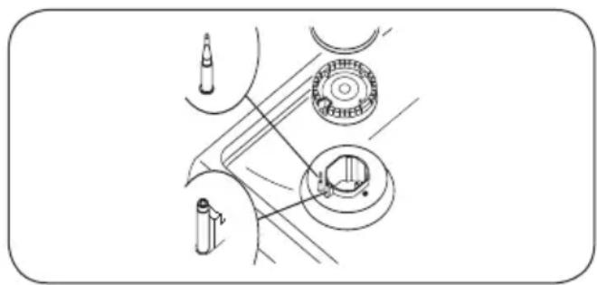
Warning! Check that the heads burners and the relative burner caps, are correctly positioned in their housings (fig. 3).

Warning! Take care not to disturb the ignition spark plugs or flame failure devices.

Warning! If you find a tap is difficult to open or close do not force it but call for technical assistance urgently.
Structure
All the cooker parts (in enamelled or painted metal, steel, or glass) should be cleaned
frequently with warm soapy water and then rinsed and dried with a soft cloth.
natural_image
Technical line drawing of a mechanical assembly with no visible text or symbolsFig. 3
Oven cavity
The oven cavity should be cleaned after each use to remove cooking residuals and or grease or sugar which, if burnt on when the oven is used again, will form deposits or unremovable stains as well as unpleasant smells.
To maintain the shine of the enamelled parts, clean them with warm soapy water, rinse and dry them thoroughly. ALWAYS wash the accessories used.
The manufacturer cannot be held liable for any damage caused by incorrect cleaning.
How to clean the inner oven door glass
One of the features of our cookers is that the inner oven door glass can be easily removed for cleaning without the aid of specialized
personnel. Just open the oven door and remove the support securing the glass (fig.4).

Caution: This operation can be done also with the door fitted on appliance, but in this way, pay attention that when the glass is pulled upwards, the force of the hinges can close the door roughly.
LOCK AT LEAST ONE HINGE (fig.6)
To reassemble the glass, proceed in the reverse order, being careful not to pinch your fingers. (fig.5)

natural_image
Illustration of a hand holding a rectangular object with internal lines, no text or symbols presentFig.4

Fig. 5
Oven door removal (for certain models)
The oven door can be removed to give easier access to the oven when cleaning.
To remove, proceed as follows:
- Open the oven door and insert rivet or nail (R) in the hole (F) of the hinge (fig. 6).
- Partially close the door, forcing it upwards at the same time to free stop tooth and hinge sector.
- Once the hinge is free, pull the door forwards tilting it slightly upwards to free sector.
- To reassemble proceed in the reverse order, paying attention to the correct position of sectors.
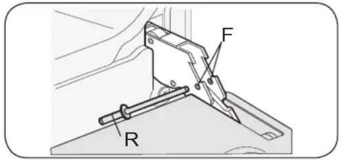
Fig. 6
Replacing the oven lamp
Ensure the appliance is switched off before replacing the lamp to avoid the possibility of electric shock.
In the event one or both oven lamps need replacing, the new lamps must comply with the following requisites: 15 W - 230 V\~ - 50 Hz - E 14 - and must be resistant to high temperature (300°C).
The appliance can have two different types of lamp holder:
Lamp holder (fig. 7): Draw out the side guide rails as described above. Then, remove the glass protection cap 2 from the bulb socket, lifting it with a screwdriver placed between the cap and the oven wall and replace the lamp 1. Fit the accessories back in reverse order.
Lamp holder (fig.8): Turn glass protection cap 2 counterclockwise and change the lamp . 1
Re-fit the cap, screwing it back in a clockwise direction.

Fig. 7

Fig.8
Oven seal
The oven seal guarantees the correct functioning of the oven. We recommend you:
- clean it, avoiding abrasive tools or products.
- check its state now and then.
If the oven door seal has become hard or is damaged, contact our Service Centre and avoid using the oven until it has been repaired.

Fig.9
Oven side-guide rails
To allow for a better cleaning of the side grids, you can extract them this way:
Push with a finger on the last of the slots to release the grid from its hold. 1
Lift it towards the top and extract the grid. 2
To put them back into place, reverse the order of this operation.
Self-cleaning panels
Oven walls are protected by panels coated with a grease-proof, microporous enamel that absorbs and eliminates splattering during baking.
If there is a lot of liquid or grease, dry immediately with a damp sponge and heat the oven for 2 hours on the maximum thermostat position. Wait for the oven to cool down and then go over it again with a damp sponge. If you are unable to remove all the substances, repeat the above procedure.
It is, however, advisable to periodically remove the panels and wash them with warm soapy water and dry them with a soft cloth.
To remove them follow these instructions:
- Extract the side grids as indicated in the previous paragraph.
- Remove both side panels 1 (fig.10).
- Remove back panel 4 by unscrewing respective locking screws 5 (fig.11).
- Repeat previous operations in reverse order to replace all elements.
Important! Position both side panels 1 by taking the locking pin 2 out of the hole 3 (fig. 10).

Fig. 10

Fig. 11
Some problems can be caused either as the results of simple maintenance operations or by incorrect selection of settings. Prior to contacting a Service Centre please check the following chart.
| Problem Remedy | |
| The appliance is not working | Make sure the gas tap is openCheck the plug is inCheck that the knobs are set correctly for cooking and then repeat the operations given in the handbookCheck the electrical system safety switches (RCD). If there is failure in the system call an electrician in. |
| The electric oven is not working | Check that the programmer accessory, if there is one, is on the manual position and then repeat the operations described in the manual |
| The thermostat is not working | Contact Service Centre . |
| The electric thermostat warning light does not switch on during use | Turn the thermostat round to a hotter temperatureTurn the selector round to a different function |
| The oven light does not switch on | Make sure the lamp is firmly screwed in placeBuy a lamp for high temperatures at one of our Service Centre and fit it following the instructions given “Replacing the oven lamp” paragraph. |
Installation
Technical information

Warning! Alwais use safety gloves while handling the cooker.
- The installation, adjustments, conversions and maintenance operations listed in this part must only be carried out by qualified personnel. The manufacturer cannot be held responsible for any damage to persons or property resulting from an incorrect installation of the appliance.
- The safety and automatic adjustment devices of the appliances may, during its life, only be modified by the manufacturer or duly authorised supplier.
- In accordance with the gas standard, the all-gas and combi appliances are “class 1” (free standing) or “class 2 subclass 1” (recessed) and, as such, must comply with the clearances specified in figure below consequently any side walls must be no higher than the work top.
- The walls adjacent to and surrounding the appliances must be able to withstand an temperature of 95°C.
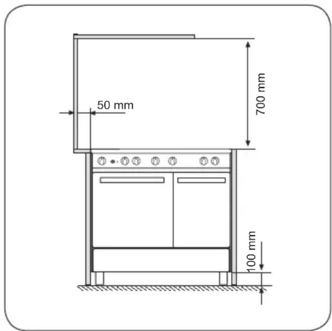
- The installation of all-gas and combi appliances must comply with the standards in force.
- This appliance is not connected to a flue for discharge of the combustion products; therefore, it must be connected in compliance with the above mentioned installation rules.
Particular attention must be paid to the instructions given below for ventilation and aeration.
Installation
Unpacking your cooker
- Once the wrapping has been removed from the outer surfaces and the various inner parts, thoroughly check that the appliance is in perfect condition. If you have any doubts do not use the appliance and call in a qualified person.
- Some parts mounted on the appliance are protected by a plastic film. This protection must be removed before using the appliance. We recommend slitting the plastic film along the edges with a sharp knife or pin.
- Do not move the appliance by the handle.
The packaging materials used (cardboard, bags, polystyrene foam, nails etc.) must not be left anywhere within easy reach of children as they are a potential hazard source.
Ventilation
The appliance should not be installed in a room of volume less than 20 m^3 .
The quantity of air necessary is that required for a regular combustion of the gas and for the ventilation of the room. The natural flow of air must be direct through permanent openings in the walls of the room that open directly to the outside with a minimum cross section of 100 cm ^2 (fig. 1). These openings must be positioned so they cannot be obstructed.
Indirect ventilation is also allowed by taking air from adjacent rooms to the one to be ventilated, strictly complying with the prescriptions of the standards in force.

fig. 1
Location and aeration
Gas cookers must always discharge the products of combustion and the moisture through hoods connected to flues or directly to the outside (fig. 2). If it is impossible to use a hood, a fan installed on the window or wall, facing the outside, is allowed and should be switched on each time the appliance is used (fig. 3) provided the rules and regulations in force relating to ventilation.
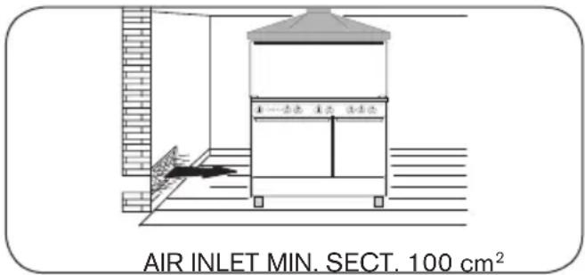
fig. 2

fig. 3
Positioning the cooker
The appliances are fitted with the following parts to enable them to be correctly positioned:
- Adjustable feet, to be fitted to the appliance, which allow the height of the cooker to be aligned with other kitchen furniture (fig. 4).
- Backguard 1. If the cookers are equipped with this accessory, leave of the factory with this particular inserted inside the packaging. In order to install the backguard, it is necessary to loosen the screws 2 positioned on the back of the hob and then to fix the backgaurd as indicated in figure 5

natural_image
Pure mechanical diagram showing a lever and pivot point with no text or symbolsfig. 4

Fig. 5
Securing the cooker to wall
Note:- The installation of the chain provided is for safety reasons, it must be installed as indicated below.
To prevent the cooker tipping forwards in the
event of children standing on the oven door or where users put extreme weight on the door when in open position, two chains MUST BE fixed to the back of the oven which should at all times be secured to the threaded pins. The threaded pins should be secured to the wall at the back of the cooker. Assembly instructions (fig.6)
- Secure threaded pins into wall immediately behind and to the left-hand side about 770 mm from the floor.
Finished fixing the chains must be stretched
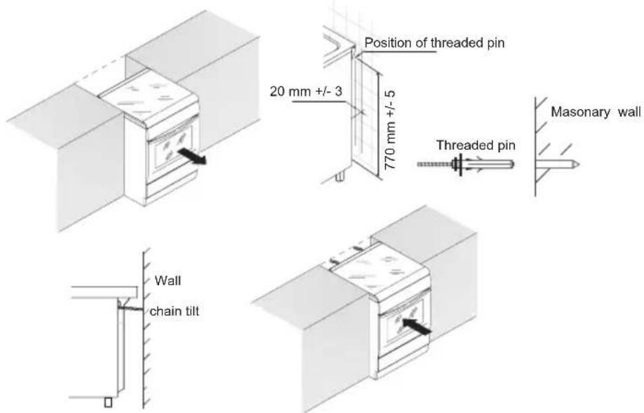
Fig. 6
Gas connection
Before connecting the appliance check that the data on the rating plate affixed to the cooker, correspond to those of the gas mains.
A label on the back of this handbook and at the back of the cooker gives the appliance adjustment conditions, that is, the type of gas and operating pressure.
When the final connection has been made, it is essential that a thorough leak test is carried out on the cooker and installation.
Ensure that the main connection pipe does not exert any strain on the cooker The appliance must be installed and serviced by a competent person as stated in the Gas Safety (Installation and Use) Regulation Current Editions and the IEE Wiring Regulations.
Any gas installation must be carried out by a competent person (GAS SAFE REGISTER engineer) to the relevant Gas Standards.
The manufacturer will not accept liability, should the above instructions or any of the other safety instructions incorporated in this book be ignored. This cooker is designed to be installed with an appliance flexible connection.
Connection is made to the RC 1/2 (1/2"
B.S.P.) female threaded located just below the hotplate level on the rear right-hand side of the cooker.
Any gas installation must be carried out by a competent person (GAS SAFE REGISTER engineer)
to the relevant Gas Standards.
The manufacturer will not accept liability, should the above instructions or any of the other safety instructions incorporated in this book be ignored.
This cooker is designed to be installed with an appliance flexible connection. Connection is made to the RC 1/2 (1/2" B.S.P.) female threaded located just below the hotplate level on the rear right-hand side of the cooker.
- The gas bayonet connector can be fitted directly behind the appliance or alternatively adjacent to the appliance.
- If fitted in a cupboard access must be available to disconnect and connect the flexible hose.
- It is recommended that a bayonet type plug in micropoint flexible hose is used.
- Recommended length - 4 feet x 3/8 inch bore.
Note:
For certain types of gas bayonet connection used, it may not be possible for the appliance to be pushed fully back to the wall stops.
Important:
Flexible tubing MUST comply with BS.669 Current Edition.

Attention! If the appliance is going to be recessed (class 2 subclass 1), connect it to the gas supply source using only flexible stainless steel, seamless pipes in accordance with the standard.

Attention! If the appliance is going to be installed free-standing (class 1) and if you use the flexible rubber hose, it is necessary to follow the instructions and the figure given below:

Attention! On its route, the hose must not touch any parts where the over temperature is than 95^ C.

Attention! The hose must not be subject to any kind of torsional stress or tractive force, there must be no pinched parts or really sharp bends.

Attention! It must not touch anything that can cut, that has sharp corners, etc.

Attention! The whole length of the hose must be easy to inspect in order to keep a check on its condition.

Attention! It must be replaced within the date printed on it.
Electrical connection
The electrical connection must be carried out in accordance with the current standards and laws in force.
Before connecting check that:
- the system and electrical sockets amperage is adequate for the appliance maximum power (see data label affixed on the back of the cooker).
- the socket or system has an effective earth connection in accordance with current standards and prescriptions of the law. All responsibility is disclaimed if this is not complied with.
- the plug and socket or the multipolar switch must be accessible after installation of the appliance.
When connecting to the mains with a socket:
- Fit to the power cable (if without) a standardized plug, suitable for the load which is indicated on the data label. Connect the wires making sure they correspond as shown below, and remember that the earth wire must be longer than the phase wires:
letter L (phase) = brown wire
letter N (neutral) = blue wire
symbol ⊕ (earth) = green/yellow wire
- The power cable must be laid so that no parts of it ever reach a temperature of 75 °C.
- For connecting do not use, adapters or shunts as they could cause false contacts resulting in hazardous overheating.
When connecting directly to the mains:
- Install a multipolar switch that can withstand the appliance load, with a minimum opening between the contacts of 3 mm. Remember that the earth wire must not be cut out by the switch.
Connecting the power cable
The all-electric cookers and some combi versions are without supply cable and are adjusted for single-phase power, butt they can, with due modifications, be powered by three phase systems by following these instructions:
- Remove the rear panel from the cooker.
- Move the connecting plates in the terminal board fig.7, following the diagram in fig. 8.
- You will also find this diagram affixed to the back of the cooker.(fig.9) according to the type of connection you want.
- Connect the power cable, whose cross section must be suitable (see paragraph «TECHNICAL FEATURES»), keeping the earth wire longer than the phase wires.
- Secure the cable in the clamp and - fit the rear panel in place.

fig.7

fig.8
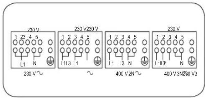
fig.9
Adjustments
- Always disconnect the appliance from the electricity supply before making any adjustment.
- All seal must be replaced by the technician following any adjustment or regulation.
- The adjustment of the reduce rate (simmer) must be undertaken only with burners functioning on natural gas while in the case of burners functioning on L.P.G, the screw must be locked down fully (in clockwise direction).
- "Primary air adjustment" on hob gas burners is unnecessary.
Taps
All gas taps are male cone type with only one way of passage.
Adjustment of the "Reduced rate" position as follows (fig.10):
- Turn the burner on and place the knob on the "Reduced rate" position (small flame).
- Remove the knob of the tap which is attached by simply applying pressure to the rod.
- Insert a small screwdriver 1 into the top shaft and turn the throttling screw 2 left or right until flame of the burner is conveniently regulated to the low position
- Check that the flame does not go out when the knob is sharply switched from the "Full on" to "Reduced rate" positions.
Attention! This operation can be carried out also with the front panel fitted, but if you find some difficulties to reach the adjustment screw, remove the front panel unscrewing the fixing screws, which are positioned in the inferior part of the same and make to slip downwards.
Gas information
To tighten some components apply the following torque forces:
Aluminium pipes to burners, valves, thermostats: 15 Nm
Thermocouples to top burners cups: 3 Nm
Thermocouples to thermostats: 4 Nm Push-on connector: 20 Nm Injectors: 4 Nm

Fig. 10
Conversions
Replacing the injectors
Our burners can be adapted to different types of gas by simply installing the injectors suitable for the gas you want to use.
To change the injectors on the hob, remove the burner cup and head and with a 7 mm ∅ socket spanner replace them (fig. 11).
To help the installer, the table on in the "Technical information" section. gives the burner nominal heat input, injector diameter and operating pressure of the different gas types.
After having replaced the injectors, it will be necessary to proceed with burner adjustment as explained in the previous paragraphs. The technician must replace any seals after the adjustments have been made.

natural_image
Mechanical device diagram showing a lever and base assembly (no text or symbols)Fig. 11
Maintenance
Prior to any maintenance work or changing parts, disconnect the appliance from the gas and electricity power sources.
Replacing the taps
Proceed in the following way when replacing a tap or the thermostat:
- Remove pan supports, burner heads.
- Unscrew the burner fixing screws (four for ultrarapid burner and two for the other burners)
- Pull out the knobs.
- Unscrew the fixing screws 1 (fig. 14) which lock the front panel to the front frame then slip out from the upper fixing brackets. 2
- Unscrew the fixing screws 1 (fig. 14 which lock the hob at the back and remove it.
- Unscrew the nuts 2 of the gas aluminium pipes and pull out the thermocouple quick connectors 3 (fig.13).
- Unscrew the screws 2 (fig. 12) which lock the crosspieces.l
- Unscrew the screws 1 (fig. 12) which unite the the bridles of the taps to the front frame.
- Make to slip the ramp toward the back part and unscrew the screws 1 (fig. 13) in order to free the taps.
- Change seal each time a tap is replaced. This will ensure perfect retention between the tap and part.
- Reassemble all the parts following the same procedure but in the reverse order.

Fig. 12

Fig. 13
Changing the flexible gas hose
In order to guarantee that the gas hose is always in excellent condition we strongly recommend changing it on the date you will find printed on it.
Replacing the electrical components
- The rear protection will have to be removed in order to change the electrical heating elements, spit motor, terminal board and power cable.
- If you have to change the power cable (see the cross section on table in the “Technical information” section), always keep the earth wire longer than the phase wires and, in addition,
follow all the instructions given in the "Electrical connection" paragraph.
- To change the oven lamp see the instructions given "Replacing the oven lamp" paragraph.
- To change the spark generator, the spark electrodes and the lamp holder the work top has to be removed as indicated in paragraph "Replacing the taps".
- To change the lamp-holder force the tabs of blockage and take the lamp-holder toward the inside of the oven.
- To change the eventual programming accessory, the thermostat, commutators, the switches and the microswitchs, , remove the front panel as indicated in paragraph "Replacing the taps".

Fig. 14
Technical information
Outside cooker dimensions
| MODEL | height1 /mm | height2 /mm | width3 /mm | depth4 /mm |
| 100 x 60 910 ÷ 920 970 ÷ 980 1000 600 | ||||
| 90 x 60 885 ÷ 920 945 ÷ 980 900 600 | ||||


Burner disposition and hob burner technical data table
| Burners | Operating pressure gas | Rate | Diameter injector Sabaf | Heat input By-pass | |||
| N. | Denomination | mbar | g/h | 1/100 mm | Min | Max | 1/100 mm |
| 1 | Ultrarapid | GPL 30Natural gas 20 | 276 | 98135-K | 16001600 | 38003800 | 62 |
| 2 | Rapid | GPL 30Natural gas 20 | 218 | 88117-Y | 800800 | 30003000 | 44 |
| 3 | Semi-rapide | GPL 30Natural gas 20 | 131 | 6898-Z | 600600 | 18001800 | 34 |
| 4 | Auxiliary | GPL 30Natural gas 20 | 73 | 5175-X | 400400 | 10001000 | 28 |
| Electric components description Nominal data | |
| Fan of the rear heating element 25..29 W | |
| Oven lamp 2 x 15 W - E 14 - T 300 | |
| Power cable H05 RR-F 3 x 1.5 mm | 2 |
| Cooling fan motor 12 W | |
| Left cavity :Top heating element | 1800+800 W |
| Lower heating element 1400 W | |
| Rear circular heating element 2000 W | |
| Right cavity :Top heating element | 475+1150 W |
| Lower heating element 950 W |
Environment concerns
The appliance was designed and made in accordance with the European standards listed below:
=> EN 30-1-1, EN 30-2-1 and EN 437 plus subsequent amendments (gas)
=> EN 60 335-1 and EN 60 335-2-6 (electrical) plus relative amendments
The appliance complies with the prescriptions of the European Directives as below:
=> 2006/95 EC concerning electrical safety (BT).
=> 2004/108 EC concerning electromagnetic compatibility (EMC)
=> 2009/142 EC concerning gas safety.
Oven accessories that could come into contact with foodstuffs are made with materials that comply with the provisions of the 89/109 EC directive dated 21/12/88.
This product complies with EU Directive 2002/96/EC.
The crossed-out dustbin symbol reported on the appliance indicates that the appliance must be disposed of separately from other domestic refuse at the end of its useful life. It must therefore be delivered to a waste recycling centre specifically for electric and electronic equipment or returned to
the retailer at the moment of purchase of a new equivalent appliance.

The user is responsible for delivering the appliance to the appropriate collection centre at the end of its useful life, Failure to do so may result in a fine, as provided for by laws governing waste disposal.
Differential collection of waste products for eventual recycling, treatment and environmentally friendly disposal helps reduce possible negative effects on the environment and health, and also enables the materials making up the product to be recycled.
For more detailed information on the available refuse collection systems, refer to the local Municipal Solid Waste disposal centre or the shop where the product was purchased.
Producers and importers are responsible for fulfilling their obligations as regards recycling, treatment and environmentally friendly disposal by directly or indirectly participating in the collection system.

www.zanussi.com/shop


- USER MANUAL
- Contents
- Safety information
- Hot surface
- Product description
- Presentation
- Description of hob controls
- Gas burner knob (fig.3)
- Right oven commutator/thermostat knob (fig.4)
- Left oven -Multifunction selector knob (fig.5)
- Red warning light
- Yellow warning light
- Electronic programmer
- Setting the time (from 0.01 to 24.00 = hh, mm)
- Minute counter (from 0.01 to 0.59 = hh, mm)
- Semi-automatic operation (with cooking time from 0.01 to 23.59 = hh, mm)
- Semi-automatic operation (with end of cooking time from 0.01 to 23.59 = hh, mm)
- Automatic operation (with the start of cooking time delayed)
- Manual operation
- Buzzer
- Correcting/cancelling the programme setting
- Hob: general notes on safety
- Automatic electric ignition of burner
- Automatically the ignition spark shoots
- Optimum use of the burners
- Oven: general notes on safety
- How to use the multifunction oven
- Left oven cavity
- Traditional cooking
- Combined traditional + fan
- cooking
- Defrosting + warm up by hot air
- Fan forced cooking
- Conventional grill cooking
- Fan grill cooking
- How to use the conventional oven
- Right oven cavity
- Traditional cookinh
- Grill cooking
- Useful cooking tips
- Cakes and bread:
- Meat:
- Grilling:
- Cleaning and maintenance
- Structure
- Oven cavity
- How to clean the inner oven door glass
- LOCK AT LEAST ONE HINGE (fig.6)
- Oven door removal (for certain models)
- Replacing the oven lamp
- Oven seal
- Oven side-guide rails
- Self-cleaning panels
- Installation
- Technical information
- Warning! Alwais use safety gloves while handling the cooker.
- Unpacking your cooker
- Ventilation
- Location and aeration
- Positioning the cooker
- Securing the cooker to wall
- Gas connection
- Note:
- Important:
- Electrical connection
- Before connecting check that:
- When connecting to the mains with a socket:
- Connecting the power cable
- Adjustments
- Taps
- Gas information
- Conversions
- Replacing the injectors
- Maintenance
- Replacing the taps
- Changing the flexible gas hose
- Replacing the electrical components
- Environment concerns
- www.zanussi.com/shop
Brand : ZANUSSI
Model : ZCK18307XA
Category : Frying Pan