
S2MP - Training equipment Body-Solid - Free user manual and instructions
Find the device manual for free S2MP Body-Solid in PDF.


| Product Type | Multi-station home gym |
| Brand | Body-Solid |
| Model | S2MP |
| Overall Dimensions | Approx. 80 x 40 x 80 inches (203 x 102 x 203 cm) |
| Weight Capacity | Up to 300 lbs (136 kg) user weight |
| Weight Stack | 200 lbs (91 kg) steel weight stack |
| Main Exercises | Lat pulldown, chest press, leg extension, leg curl, tricep pushdown |
| Adjustable Pulleys | Yes, high and low pulley stations |
| Frame Material | 11-gauge steel tubing |
| Upholstery | High-density foam with durable vinyl |
| Cable System | Nylon-coated steel cables |
| Weight Selector | Standard selector pin with safety key |
| Seat Adjustment | Yes, adjustable slide seat |
| Backrest Adjustment | Yes, multiple positions |
| Foot Plates | Rubber-coated and adjustable |
| Assembly Required | Yes, includes tools and manual |
| Warranty | Limited lifetime on frame, 2 years on parts |
| Cleaning Instructions | Wipe down with damp cloth, no harsh chemicals |
| Safety Features | Spotter platform, safety bars, and weight stack guards |
| Spare Parts Availability | Available via Body-Solid or authorized dealers |
Frequently Asked Questions - S2MP Body-Solid
User questions about S2MP Body-Solid
0 question about this device. Answer the ones you know or ask your own.
Ask a new question about this device
Download the instructions for your Training equipment in PDF format for free! Find your manual S2MP - Body-Solid and take your electronic device back in hand. On this page are published all the documents necessary for the use of your device. S2MP by Body-Solid.
USER MANUAL S2MP Body-Solid
Body-Solid® Built for Life

natural_image
Technical line drawing of a fitness equipment machine with lever and pump components (no text or symbols)S2MP
Warning, Safety & Maintenance
Be sure that all users carefully read and understand all warning, safety and maintenance labels on the machine before each use. Failure to do so may result in death or serious injury.
It is imperative that you retain this Owner's Manual and be sure all warning labels are legible and intact. Replacement Owner's Manuals and warning labels are available from your local Body-Solid dealer.
If you have any questions about the operation, set up or maintenance of this machine please call our customer service department at 1 (800) 556-3113.
THERE IS A RISK ASSUMED BY INDIVIDUALS WHO USE THIS TYPE OF EQUIPMENT. TO MINIMIZE RISK, YOU MUST FOLLOW THESE RULES:
- Inspect equipment before each workout. Check that all nuts, bolts, screws and pop pins are in place and fully tightened. Also, before use, check cables for signs of wear. Replace all worn parts immediately. Never use machine if any parts are damaged or missing. FAILURE TO FOLLOW THESE RULES MAY RESULT IN SERIOUS INJURY.
- Keep clear of the cables and all moving parts when the machine is in use.
- Always make sure all Snap Links are closed when doing any cable/pulley/strap exercises.
- Exercise with care. Perform your exercises at a smooth moderate pace; never perform jerky or uncoordinated movements that may cause injury.
- It is recommended that you should workout with a training partner.
- Do not allow children or minors to play on or around this equipment.
- If unsure of proper use of equipment, call your local Body-Solid distributor or the Body-Solid customer service department at 1-800-556-3113.
- WARNING: Consult your physician before starting your exercise program. For your own safety, do not begin any exercise program without proper instruction. RAL8-6-03 WC-54
WARNING
Safety and Maintenance of Cables
IMPORTANT: Cables are wear items. It is your responsibility to prevent unexpected breakage. Cable inspection should be performed daily. Inspect all cables, the nylon coating on all cables, and the area near the fitting at each end of each cable. Replace any damaged or worn cable immediately. Do not allow the machine to be used until damaged or worn cables are replaced. Using or allowing a machine to be used with a suspect cable can result in serious injury. See Owner's Manual for more information.
For Body-Solid Customer Service Call 1-800-556-3113
| MAINTENANCE SCHEDULE Check the function and integrity of the following components. As noted, Inspect equipment before each workout. Replace all damaged, broken or worn components immediately. | D A I L Y | W E K L Y | |
| Cables: | Check tension, end fittings, and coating | √ | √ |
| Check that locking nut at weight stack is tight | |||
| Upholstery: Wipe down and dry Clean and condition | √ | √ | |
| Frame: | Wipe down and dry Polish / Wax | √ | √ |
| Chrome: | Wipe down and dry Polish / Lubricate | √ | √ |
| Nuts / Bolts / Fasteners: Tighten and/or adjust as needed | √ | ||
| Guide Rods: Lubricate and clean | √ | ||
| Linear Rods: Lubricate and clean | √ | ||
| Seat Sleeves: Lubricate and clean | √ | ||
| Adjustments / Locking Pins / Tightening Knobs | √ | ||
| Weight Stack Pins | √ | ||
| Warning Instruction Labels | √ | ||
| Springs/Pop Pins | √ | ||
| Anti Skid Surfaces | √ | ||
| Hand Grips/Rollers | √ | ||
Table of Contents
• SAFETY INSTRUCTIONS...... PAGE 4
- PREPARATION...... PAGE 5
- HARDWARE LIST...... PAGE 6
- HARDWARE ILLUSTRATION...... PAGE 8
• PART / LIST ILLUSTRATION...... PAGE 13
• ASSEMBLY INSTRUCTIONS...... PAGE 20
- EXPLODED VIEW...... PAGE 33
- CONTACT PAGE...... PAGE 34
Important Safety Instructions
Before beginning any fitness program, you should obtain a complete physical examination from your physician.
When using exercise equipment, you should always take basic precautions, including the following:
Read all instructions before using the S2MP. These instructions are written to ensure your safety and to protect the unit.
Do not remove any safety labels from the machine.
○ Do not allow children on or near the equipment.
Use the equipment only for its intended purpose as described in this guide. Do not use accessory attachments that are not recommended by the manufacturer. Such attachments might cause injuries.
○ Wear proper exercise clothing and shoes for your workout, no loose clothing.
Keep hands, limbs, loose clothing, and long hair well out of the way of all moving parts.
○ Use care when getting on or off the unit.
Do not overexert yourself or work to exhaustion.
○ If you feel any pain or abnormal symptoms, stop your workout immediately and consult your physician.
Never operate unit when it has been dropped or damaged. Return the equipment to a service center for examination and repair.
Never drop or insert objects into any opening in the equipment.
Always check the unit and its cables before each use. Make sure that all fasteners and cables are secure and in good working condition.
○ Do not use the equipment outdoors or near water.
Personal Safety During Assembly
Before beginning assembly, please take the time to read the instructions thoroughly.
Read each step in the assembly instructions and follow the steps in sequence. Do not skip ahead. If you skip ahead, you may learn later that you have to disassemble components and that you may have damaged the equipment.
○ Assemble and operate the S2MP on a solid, level surface. Locate the unit a few feet from the walls or furniture to provide easy access.
The S2MP is designed for your enjoyment. By following these precautions and using common sense, you will have many safe and pleasurable hours of healthful exercise with your Body-Solid Multi Press Machine.
After assembly, you should check all functions to ensure correct operation. If you experience problems, first recheck the assembly instructions to locate any possible errors made during assembly. If you are unable to correct the problem, call the dealer from whom you purchased the machine or call 1-800-556-3113 for the dealer nearest you.
Obtaining Service
Please use this Owner's Manual to make sure that all parts have been included in your shipment. When ordering parts, you must use the part number and description from this Owner's Manual. Use only Body-Solid replacement parts when servicing this machine. Failure to do so will void your warranty and could result in personal injury.
For information about product operation or service, check out the official Body-Solid website at www.bodysolid.com or contact an authorized Body-Solid dealer or a Body-Solid factory-authorized service company or contact Body-Solid customer service at one of the following:
Toll Free: 1-800-556-3113
Phone: 1-708-427-3555
Fax: 1-708-427-3556
Hours: M-F 8:30-5:00 CST
E-Mail: service@bodysolid.com
Or write to: Body-Solid, Inc. Service Department 1900 S. Des Plaines Ave. Forest Park, IL 60130 USA
Retain this Owner's Manual for future reference. If you need to order replacement parts please be prepared to provide the following information when contacting us so that we can assist you better.
- Model Number
- Place of Purchase
- Serial Number (S/N)
- Part # and Description
Preparation
Thank you for purchasing the S2MP. This bench is part of the Body-Solid line of quality strength training machines, which lets you target specific muscle groups to achieve better muscle tone and overall body conditioning. To maximize your use of the equipment please study this Owner's Manual thoroughly.
Required Tools
The basic tools that you must obtain before assembling the S2MP include but are not limited to:
Metric Allen Key Set
○ Standard Allen Key Set
○ Standard Wrench Set
Metric Wrench Set
○ Adjustable Wrench
○ Screwdriver (standard and/or phillips)
Installation Requirements
Follow these installation requirements when assembling the S2MP:
Set up the S2MP on a solid, flat surface. A smooth, flat surface under the machine helps keep it level. A level machine has fewer malfunctions.
Provide ample space around the machine. Open space around the machine allows for easier access.
Insert all bolts in the same direction. For aesthetic purposes, insert all bolts in the same direction unless specified (in text or illustrations) to do otherwise.
Leave room for adjustments. Tighten fasteners such as bolts, nuts, and screws so the unit is stable, but leave room for adjustments. Do not fully tighten fasteners until instructed in the assembly steps to do so.
Fill out and mail the warranty card.
Assembly Tips
Read all "Notes" on each page before beginning each step.
While you may be able to assemble the S2MP using the illustrations only, important safety notes and other tips are included in the text.
Some pieces may have extra holes that you will not use. Use only those holes indicated in the instructions and illustrations.
NOTE: With so many assembled parts, proper alignment and adjustment is critical. While tightening the nuts and bolts, be sure to leave room for adjustments.
NOTE: The bottles that are marked "Poison" is your touch up paint. Keep away from children.
CAUTION: Obtain assistance! If you feel like you can't assemble the S2MP by yourself then do not attempt to do so as this could result in injury. Review the installation requirements before proceeding with the following steps.
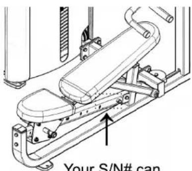
Your S/N# can be found here
Body-Solid continually seeks ways to improve the performance, specifications and product manuals in order to ensure that only superior products are released from our factories. Please take the time to carefully read through this manual thoroughly. Instructions contained in this document are not intended to cover all details or variations possible with Body-Solid equipment, or to cover every contingency that may be met in conjunction with installation, operation, maintenance or troubleshooting of the equipment. Even though we have prepared this manual with extreme care, neither the publisher nor the author can accept responsibility for any errors in, or omission from, the information given. Should additional information be required, or should situations arise that are not covered by this manual, the matter should be directed to your local Body-Solid representative, or the Service Department at Body-Solid Inc. in Forest Park, Illinois.
S2MP Hardware List
| Part# | Size | Description | Quantity |
| 1 | M10X25mm | FLAT HEAD CAP SCREW | 8 PCS. |
| 2 | M10X30mm | HEX HEAD BOLT | 6 PCS. |
| 3 | M10X35mm | HEX HEAD BOLT | 1 PCS. |
| 4 | M10X45mm | HEX HEAD BOLT | 1 PCS. |
| 5 | M10X50mm | HEX HEAD BOLT | 8 PCS. |
| 6 | M10X60mm | HEX HEAD BOLT | 1 PCS. |
| 7 | M10X65mm | HEX HEAD BOLT | 2 PCS. |
| 8 | M10X75mm | HEX HEAD BOLT | 1 PCS. |
| 9 | M12X125mm | HEX HEAD BOLT | 1 PCS. |
| 10 | M12X35mm | HEX HEAD BOLT | 8 PCS. |
| 11 | M8X25mm | SOCKET HEAD CAP SCREW | 2 PCS. |
| 12 | M4X8mm | SET SCREW | 1 PCS. |
| 13 | M6X6mm | SET SCREW | 4 PCS. |
| 14 | M8X8mm | SET SCREW | 4 PCS. |
| 15 | M6X16mm | PHILLIPS HEAD SCREW | 3 PCS. |
| 16 | ø9.4X86mm | SOCKET HEAD CAP SCREW | 4 PCS. |
| 17 | M8X25mm | BUTTON HEAD CAP SCREW | 4 PCS. |
| 18 | 3/8”X2.0” | SOCKET HEAD CAP SCREW | 1 PCS. |
| 19 | 10-32X1/8” | SET SCREW | 16 PCS. |
| 40 | M16 | FLANGE NUT | 1 PCS. |
| 41 | M10 | NYLON LOCK NUT | 11 PCS. |
| 42 | M12 | NYLON LOCK NUT | 9 PCS. |
| 43 | M8 | NYLON LOCK NUT | 10 PCS. |
| 44 | 1/2” | HEX NUT | 1 PCS. |
| 50 | ø10mm | SPRING WASHER | 7 PCS. |
| 51 | ø11Xø20X2mm | FLAT WASHER | 31 PCS |
S2MP Hardware List
| Part# | Size | Description | Quantity |
| 52 | 13X 24X2.5mm | FLAT WASHER | 18 PCS. |
| 53 | 6.6X 12X1.6mm | FLAT WASHER | 3 PCS. |
| 54 | 9X 16X1.6mm | FLAT WASHER | 10 PCS. |
| 55 | 3/8” | SPRING WASHER | 1 PCS. |
| 56 | 1/2” | SPRING WASHER | 1 PCS. |
S2MP Hardware Illustration
Part #1

FLAT HEAD CAP SCREW M10X25mm

QTY. 8
HEX HEAD BOLT M10X30mm
QTY. 6
Part #2
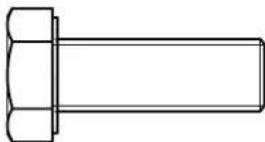

QTY. 1
Part #3
HEX HEAD BOLT M10X35mm

natural_image
Technical line drawing of a bolt with hexagonal head and rectangular body (no text or symbols)
QTY. 1
Part #4
HEX HEAD BOLT M10X45mm
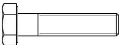
natural_image
Technical line drawing of a hexagonal bolt head (no text or symbols)
QTY. 8
Part #5
HEX HEAD BOLT M10X50mm

natural_image
Technical line drawing of a bolt with hexagonal head and rectangular shaft (no text or symbols)
Part #6
HEX HEAD BOLT M10X60mm
QTY. 1

S2MP Hardware Illustration
Part #7
HEX HEAD BOLT M10X65mm
QTY. 2

natural_image
Technical line drawing of a hexagonal bolt head (no text or symbols)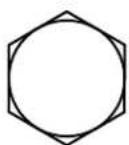
QTY. 1
Part #8
HEX HEAD BOLT M10X75mm
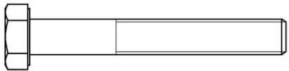
natural_image
Technical line drawing of a hexagonal bolt head (no text or symbols)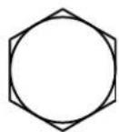
Part #9
HEX HEAD BOLT M12X125mm
QTY. 1

natural_image
Technical line drawing of a bolt with hexagonal head and rectangular shaft (no text or symbols)
QTY. 8
Part #10
HEX HEAD BOLT M12X35mm
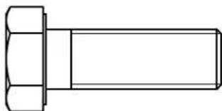
natural_image
Technical line drawing of a hexagonal bolt head (no text or symbols)
SOCKET HEAD CAP SCREW M8X25mm
QTY. 2
Part #11
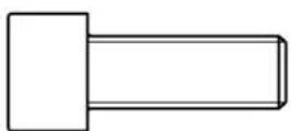

SET SCREW M4X8mm
QTY. 1
Part #12


S2MP Hardware Illustration
Part #13
SET SCREW M6X6mm
QTY. 4


Part #14
SET SCREW M8X8mm
QTY. 4


Part #15
PHILLIPS HEAD SCREW M6X16mm
QTY. 3

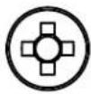
Part #16
SOCKET HEAD CAP SCREW ∅9.4X86mm
QTY. 4

natural_image
Simple line drawing of a cylindrical mechanical component with a flanged end (no text or symbols)
Part #17
BUTTON HEAD CAP SCREW M8X25mm
QTY. 4


Part #18
SOCKET HEAD CAP SCREW 3/8"X2.0"
QTY. 1

natural_image
Simple line drawing of a rectangular object with a rounded top and a flat base (no text or symbols)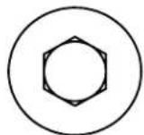
Part #19
SET SCREW 10-32X1/8"
QTY. 16


S2MP Hardware Illustration
Part #40

FLANGE NUT M16

natural_image
Geometric diagram of concentric circles with hexagonal and circular outlines, no text or symbols presentQTY. 1
Part #41

NYLON LOCK NUT M10
QTY. 11
Part #42

NYLON LOCK NUT M12

QTY. 9
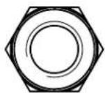
Part #43

NYLON LOCK NUT M8
QTY. 10
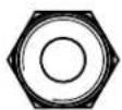
Part #44
HEX NUT 1/2"
QTY. 1

Part #50

SPRING WASHER ∅10mm
QTY. 7

S2MP Hardware Illustration
Part #51 FLAT WASHER ø11Xø20X2mm QTY. 31


Part #53 FLAT WASHER ø13Xø24X2.5mm QTY. 18
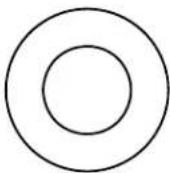

Part #53 FLAT WASHER ∅6.6X∅12X1.6mm QTY. 3


Part #54 FLAT WASHER ∅9X∅16X1.6mm QTY. 10

Part #55 SPRING WASHER 3/8" QTY. 1


Part #56 SPRING WASHER 1/2" QTY. 1



S2MP Parts List/Illustration
PART A -- FRAME A, 1 PCS

natural_image
Technical line drawing of a mechanical support structure with no visible text or symbolsnatural_image
Isometric line drawing of a rectangular metal bracket with flanges and mounting holes (no text or symbols)PART C -- FRAME C, 1 PCS

natural_image
Technical line drawing of a mechanical bracket component (no text or symbols)PART D -- FRAME D, 1 PCS
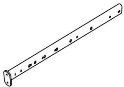
natural_image
Line drawing of a cylindrical metal rod with evenly spaced holes (no text or symbols)PART E -- FRAME E, 1 PCS

natural_image
Technical line drawing of a mechanical bracket with mounting holes (no text or symbols)PART F -- FRAME F, 1 PCS

natural_image
Technical line drawing of a mechanical bracket or support structure (no text or symbols)PART G -- FRAME G, 1 PCS
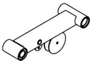
natural_image
Simple line drawing of a mechanical device with rollers and pulleys (no text or symbols)PART H -- FRAME H, 1 PCS

natural_image
Simple line drawing of a mechanical clamp or bracket (no text or symbols)S2MP Parts List/Illustration
PART WA -- WEIGHT STACK FRAME, 1 PCS

natural_image
Technical line drawing of a rectangular frame with mounting flanges and vertical supports (no text or symbols)PART WB -- SHORT METAL SHROUD, 1 PCS

PART WC -- LONG METAL SHROUD, 1 PCS

PART WD -- CHROME GUIDE ROD, 2 PCS ∅19X1229mm
PART WE -- FRONT SHROUD, 1 PCS

natural_image
Simple line drawing of a folded paper or sheet with a slot (no text or symbols)PART WF -- BACK SHROUD, 1 PCS
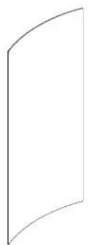
natural_image
Simple line drawing of a curved rectangular shape with no text or symbolsPART WG -- TOP SHROUD, 1 PCS

natural_image
Line drawing of a circular mechanical component with two mounting holes (no text or symbols)PART #60 -- TOP PLATE, 1 PCS

natural_image
Technical line drawing of a mechanical component with three cylindrical features and mounting holes (no text or symbols)S2MP Parts List/Illustration
PART #61 -- SELECTOR ROD, 1 PCS

PART #62 -- SELECTOR ROD TOP BOLT, 1 PCS
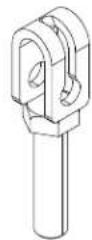
PART #63 -- CYLINDER CABLE LOCK, 1 PCS

natural_image
Isometric line drawing of a cylindrical mechanical part with cutouts (no text or symbols)PART #64 -- SEAT PAD, 1 PCS

natural_image
Simple hand-drawn oval shape with no text or symbolsPART #65 -- BACK PAD, 1 PCS
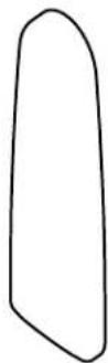
PART #66 -- SHORT POP PIN, 1 PCS

natural_image
Technical line drawing of a mechanical connector or fitting (no text or symbols)PART #67 -- SELECTOR PLATE, 1 PCS

natural_image
Simple line drawing of a curved, elongated object with six circular holes (no text or symbols)PART #68 -- LONG POP PIN, 1 PCS
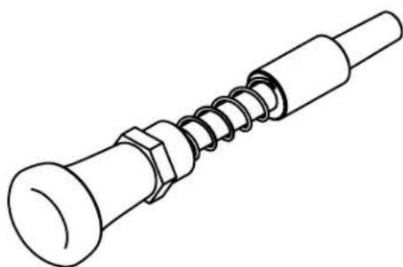
natural_image
Line drawing of a mechanical screw with threaded shaft and hexagonal nut (no text or symbols)S2MP Parts List/Illustration
PART #69 -- FOOT PAD, 4 PCS

natural_image
Isometric line drawing of a rectangular tray with three circular holes (no text or symbols)PART #70 -- SELECTOR PIN, 1 PCS

natural_image
Technical line drawing of a mechanical clamp or spring with a coiled spring and cylindrical rod (no text or symbols)PART #71 -- WHEEL, 4 PCS
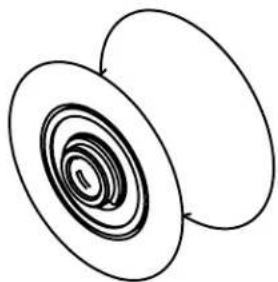
natural_image
Abstract diagram of two overlapping ovals with concentric spiral patterns (no text or symbols)PART #72 -- NYLONG BUSHING, 2 PCS ∅20X16mm

natural_image
Simple line drawing of a cylindrical mechanical part (no text or symbols)natural_image
Isometric line drawing of a mechanical ring or washer (no text or symbols)PART #75 -- BUSHING, 1 PCS

PART #76 -- LONG HANDLE SLEEVE, 2 PCS

natural_image
Simple line drawing of a hollow cylindrical object (no text or symbols)S2MP Parts List/Illustration
PART #77 -- SHAFT PIN, 3 PCS ∅25X120mm
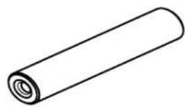
natural_image
Simple line drawing of a rolled-up cylindrical object (no text or symbols)PART #81 -- NYLON BUSHING, 2 PCS ∅17X10.5mm

PART #78 -- SHAFT PIN, 1 PCS ∅25X178mm

natural_image
Simple line drawing of a cylindrical object with a circular end and central hole (no text or symbols)PART #82 -- SHORT HANDLE SLEEVE, 2 PCS

natural_image
Simple line drawing of a hollow cylindrical object (no text or symbols)PART #79 -- END CAP, 8 PCS

natural_image
Simple line drawing of a mechanical ring or washer (no text or symbols)PART #83 -- RUBBER DONUT, 2 PCS

natural_image
Simple line drawing of a cylindrical object with a central hole (no text or symbols)PART #80 -- BUSHING, 4 PCS ∅25X18mm
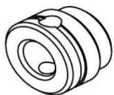
natural_image
Technical line drawing of a mechanical component with concentric rings and a central hole (no text or symbols)PART #84 -- SHAFT COLLAR, 2 PCS
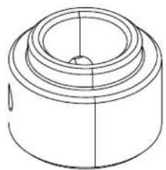
natural_image
Technical line drawing of a cylindrical mechanical component with concentric rings and a central hole (no text or symbols)S2MP Parts List/Illustration
PART #85 -- END CAP, 2 PCS 25X76mm

natural_image
Technical line drawing of a multi-layered mechanical component (no text or symbols)PART #86 -- END CAP, 1 PCS 50X76mm

natural_image
Stacked rectangular objects resembling a laptop or document stack (no text or symbols)PART #87 -- CABLE CONNECTOR, 1 PCS

natural_image
Pure technical line drawing of a mechanical component (no text or symbols)PART #88 -- BUSHING, 2 PCS ∅25X13mm

PART #81 -- BUSHING, 6 PCS ∅38X18mm
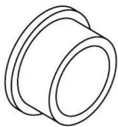
natural_image
Simple line drawing of a mechanical component with concentric rings (no text or symbols)PART #90 -- 4.5" PULLEY, 6 PCS

natural_image
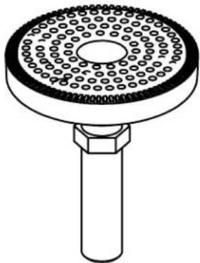
Technical line drawing of a pulley or washer component (no text or symbols)PART #91 -- ADJUSTMENT PAD, 1 PCS
natural_image
Technical line drawing of a circular mechanical component with evenly spaced holes and a central shaft (no text or symbols)PART #92 -- ROUND RUBBER PAD, 1 PCS

S2MP Parts List/Illustration
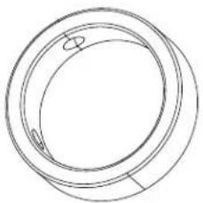
PART #93 -- HANDLE RING, 4 PCS
natural_image
Simple line drawing of a circular mechanical component with two small features (no text or symbols)PART #94 -- HANDLE END CAP, 4 PCS S

natural_image
Simple line drawing of two overlapping circles with no text or symbolsPART #102 -- CABLE, 1 PCS 4730mm

STEP 1
Be careful to assemble all components in the sequence they are presented.
NOTE:
Finger tighten all hardware in this step. DO NOT wrench tighten unless instructed. Some components may be pre-assembled. Nylon lock nuts will not fully screw onto bolts, they must be wrench tighten to fully go on.
1A. Attach Frame B (B) to Frame A (A) using:
4 - (#10) M12X35mm Hex Head Bolt
8 - (#52) 13X24mm Flat Washer
4 - (#42) M12 Nylon Lock Nut
1B. Attach Frame H (H) to Frame G (G) using:
2 - (#1) M10X25mm Flat Head Cap Screw
1 - (#77) 25mmX120mm Shaft Pin
2 - (#79) 38mm End Cap
Note: 1) Please make sure the key slot of the Shaft Pin is aligned with the key slot hole of Frame G.
2) You may need to use a mallet when inserting the Shaft Pin.

natural_image
Technical line drawing of a mechanical assembly with articulated arms and mounting feet (no text or symbols)Above shows Step 1 assembled and completed.
STEP
1

STEP 2
Be careful to assemble all components in the sequence they are presented.
NOTE:
Finger tighten all hardware first in this step. Wrench tighten ALL hardware at the end of STEP 2A. Some components may be pre-assembled. Nylon lock nuts will not fully screw onto bolts, they must be wrench tighten to fully go on.
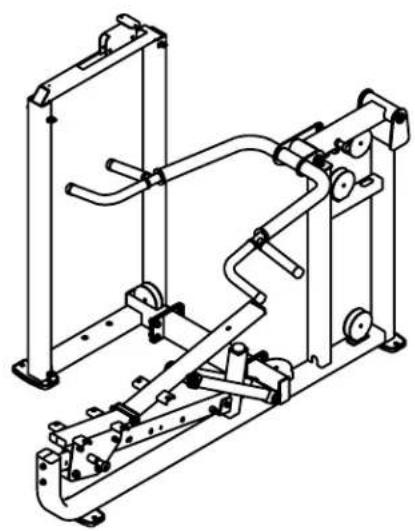
2A. Route Cable (#107) through Frame C (C) and Weight Stack Frame (WA) as shown in Step 2 drawing before connect the frames together.
2B. Attach Frame B (B) to Weight Stack Frame (WA) using:
4 - (#10) M12X35mm Hex Head Bolt
8 - (#52) M13X24mm Flat Washer
4 - (#42) M12 Nylon Lock Nut
natural_image
Technical line drawing of a mechanical assembly with articulated arms and mounting holes (no text or symbols)Above shows Step 2 assembled and completed
STEP
2


Be careful to assemble all components in the sequence they are presented.
NOTE:
Finger tighten all hardware first in this step. Wrench tighten ALL hardware at the end of STEP 31. Some components may be pre-assembled. Nylon lock nuts will not fully screw onto bolts, they must be wrench tighten to fully go on.
3A. Install Chrome Guide Rods (WD) into the holes in the Weight Stack Frame (WA).
Note: Install the rod ends with side holes into the bottom section of the Weight Stack Frame
3B. Install Rubber Donuts (#83) and slide to the bottom of the Guide Rods
3C. Tilt Guide Rods (WD) away from the Weight Stack Frame (WA) and install 20pcs of weight plates (#105). Be careful to hold guide rods steadily when installing weight plates.
Note: Please make sure the grooves of the weight plates are faced down during installation.
3D. Install Top Plate & Selector Rod Assembly (#18, #55, #60, #61) onto the Guide Rods.
3E. Install the Selector Rod Top Bolt (#62), the 1/2" Lock Nut (#44) and the 1/2" Spring Washer (#56) onto the Top Plate (#).
3F. Install Shaft Collars (#84) onto the Guide Rods so they are directly below the guide rod holes in the upper section of the Weight Stack Frame.
3G. Slide Shaft Collars (#84) upward so they lock the guide rods into position by tightening the Set Screws (#14)
- Install Weight Stack Pin (#70) using the key ring end through the Selector Rod Top Bolt (#62).

natural_image
Technical line drawing of a mechanical device with springs and lever mechanism (no text or symbols)Above shows Step 3 assembled and completed
STEP
3


Be careful to assemble all components in the sequence they are presented.
NOTE:
Finger tighten all hardware first in this step. Wrench tighten ALL hardware at the end of STEP 4E. Some components may be pre-assembled. Nylon lock nuts will not fully screw onto bolts, they must be wrench tighten to fully go on.
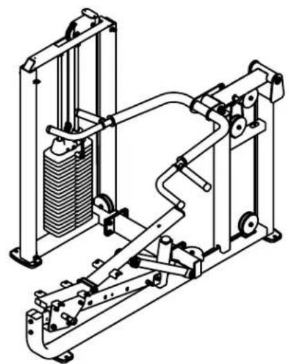
4A. Install Cable (#102) by first assembling the ball end into the Selector Rod Top Bolt (#62) and attaching the Cable Cylinder Lock (#63) over the ball end of the cable. Secure it by tighten in the Set Screw (#12)
4B. Install the M10X35mm Hex Head Bolt (#3) through the slot hole of the Selector Rod Top Bolt (#62) by fastening the M10 Nylon Lock Nut (#41).
4C. Route Cable (#102) while installing seven Pulleys (#90) into frames as shown in Step 5 Drawing using
7 - (#5) M10X50mm Hex Head Bolt
14 - (#51) 11X20mm Flat Washer
7 - (#41) M10 Nylon Lock Nut
4D. Attach Cable (#102) to Cable Connector (#87).
4E. Attach Cable Connector (#87) to Frame G (G) using:
1 - (#4) M10X45mm Hex Head Bolt
2 - (#51) M10 Flat Washer
1 - (#41) M10 Nylon Lock Nut
1 - (#75) Sleeve (Shrink Wrapped with #87)
natural_image
Technical line drawing of a mechanical assembly with spring-loaded frame and mounting bracket (no text or symbols)Above shows Step 4 assembled and completed.


STEP
4
STEP 5
Be careful to assemble all components in the sequence they are presented.
NOTE:
Wrench tighten ALL hardware at the end of Each Step. Some components may be pre-assembled. Nylon lock nuts will not fully screw onto bolts, they must be wrench tighten to fully go on.
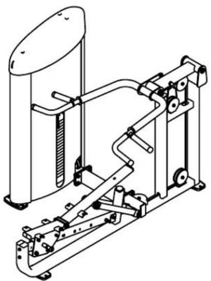
5A. Attach Short Metal Shrouds (WB) and Long Metal Shrouds (WC) to Weight Stack Frame (WA) using:
4 - (#17) M8X25mm Button Head Cap Screw
8 - (#54) 9X16mm Flat Washer
4 - (#43) M8 Nylon Lock Nut
5B. Bend the Plastic Shrouds (WE & WF) and insert them to the side slots of the Metal Shrouds (WB & WC).
5C. Attach Top Shroud (WG) to Weight Stack Frame (WA) using:
3 - (#15) M6X16mm Phillips Head Screw
3 - (#53) 6.6X12mm Flat Washer
natural_image
Technical line drawing of a mechanical exercise machine (no text or symbols)Above shows Step 5 assembled and completed.
STEP
5

Be careful to assemble all components in the sequence they are presented.
NOTE:
Finger tighten all hardware first in this step. Wrench tighten ALL hardware at the end of STEP 6B. Some components may be pre-assembled. Nylon lock nuts will not fully screw onto bolts, they must be wrench tighten to fully go on.
6A. Attach Seat Pad (#64) to Seat Frame (C) using:
4 - (#2) M10x30mm Hex Head Bolt
4 - (#50) 10mm Spring Washer
4 - (#51) 11X20mm Flat Washer
6B. Attach Back Seat Pad (#65) to Back Seat Frame (F) using:
2 - (#2) M10x30mm Hex Head Bolt
1 - (#5) M10x50mm Hex Head Bolt
3 - (#50) 10mm Spring Washer
3 - (#51) 11X20mm Flat Washer

natural_image
Line drawing of a fitness equipment machine with vertical arm and circular top (no text or symbols)Above shows Step 6 assembled and completed

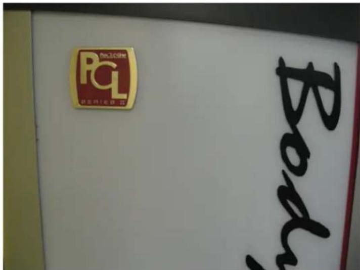
PCL Badge Location
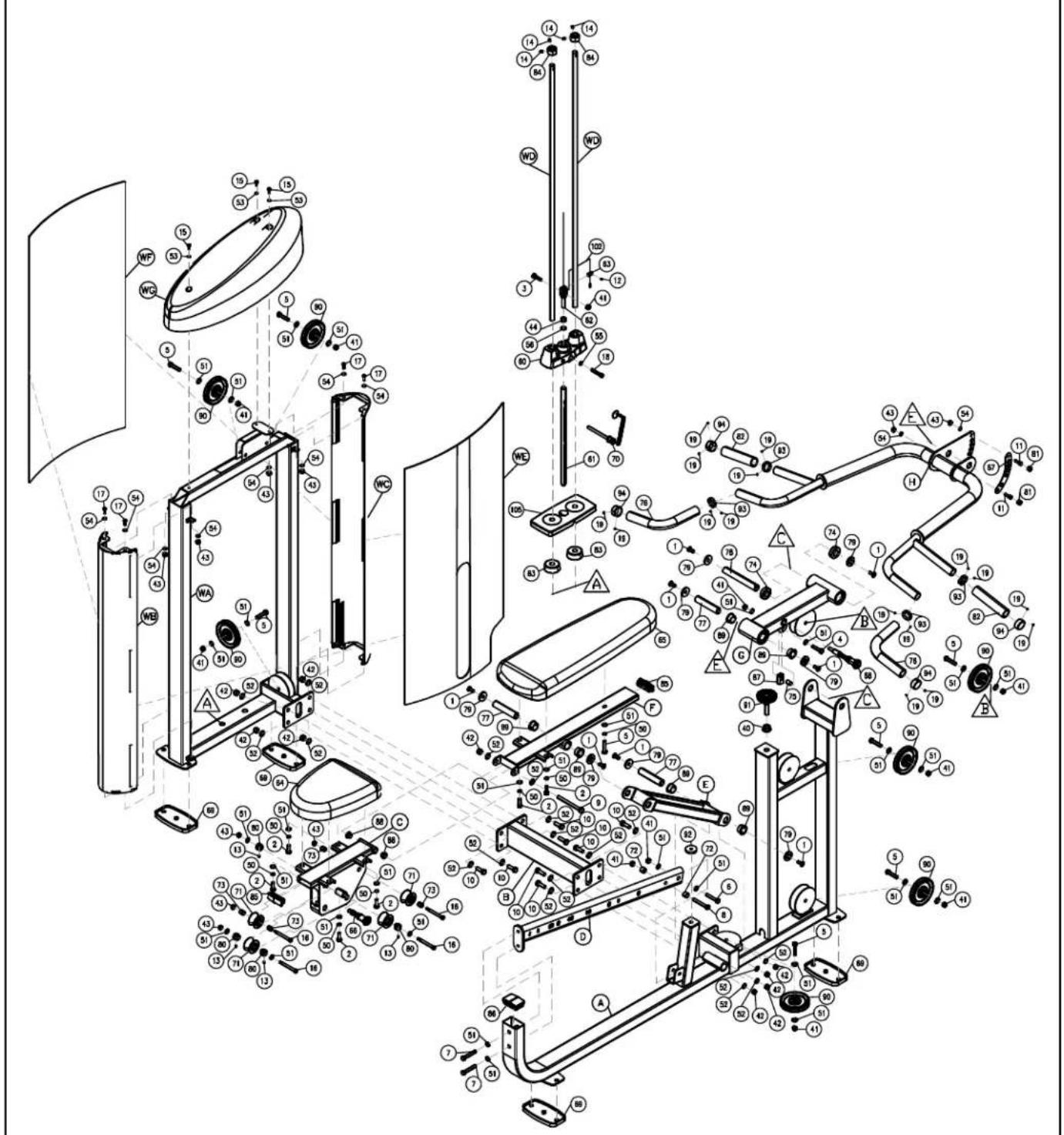
S2MP Exploded View
Body-Solid® Built for Life
S2MP
PLEASE WRITE YOUR SERIAL NUMBER IN THE BOXES BELOW
S/N # 008175-□□-□□-□□□□-□□□□
1900 S. Des Plaines Ave.
Forest Park, Il 60130
Phone:(708)427-3555
Fax:(708)427-3556
Hours: M-F 8:30 - 5:00 CST
www.bodysolid.com
- Body-Solid® Built for Life
- Warning, Safety & Maintenance
- THERE IS A RISK ASSUMED BY INDIVIDUALS WHO USE THIS TYPE OF EQUIPMENT. TO MINIMIZE RISK, YOU MUST FOLLOW THESE RULES:
- WARNING
- Safety and Maintenance of Cables
- Table of Contents
- Important Safety Instructions
- When using exercise equipment, you should always take basic precautions, including the following:
- Personal Safety During Assembly
- Obtaining Service
- Preparation
- Required Tools
- Installation Requirements
- Assembly Tips
- S2MP Hardware Illustration
- S2MP Parts List/Illustration
- STEP 1
- Be careful to assemble all components in the sequence they are presented.
- STEP 2
- STEP 5
- PCL Badge Location
- S2MP Exploded View
- S2MP
- PLEASE WRITE YOUR SERIAL NUMBER IN THE BOXES BELOW
- S/N # 008175-□□-□□-□□□□-□□□□
Brand : Body-Solid
Model : S2MP
Category : Training equipment