
CHE-HDBT300U - Receiver Comprehensive - Free user manual and instructions
Find the device manual for free CHE-HDBT300U Comprehensive in PDF.


| Product Type | HDBaseT Receiver |
| Model | CHE-HDBT300U |
| Brand | Comprehensive |
| Input Interface | HDMI (Type-A female) |
| Output Interface | RJ-45 (HDBaseT) |
| Max Resolution | 4K@60Hz 4:4:4 with HDR |
| Maximum Extension Distance | 100m (Cat6 cable) |
| Power Supply | PoE (802.3af) or 5V DC via power adapter |
| Power Consumption | 2.5W (typical) |
| Dimensions (W x D x H) | 120 x 70 x 25 mm |
| Weight | 200 g (approx.) |
| Supported Audio Formats | LPCM 7.1, Dolby TrueHD, DTS-HD Master Audio |
| HDCP Support | HDCP 2.2 |
| LED Indicators | Power, Link, Signal |
| Housing Material | Metal (aluminum alloy) |
| Operating Temperature | 0°C to 45°C |
| Storage Temperature | -10°C to 70°C |
| Humidity | 20% to 90% RH (non-condensing) |
| Maintenance | Keep dry, clean with a soft, lint-free cloth. Avoid solvents. |
| Safety | Do not expose to rain or moisture. Use only specified power supply. |
| Spare Parts | Power adapter and mounting brackets available separately. |
| Warranty | 1 year limited warranty (if applicable) |
| Application | Home theater, conference rooms, digital signage |
Frequently Asked Questions - CHE-HDBT300U Comprehensive
User questions about CHE-HDBT300U Comprehensive
0 question about this device. Answer the ones you know or ask your own.
Ask a new question about this device
Download the instructions for your Receiver in PDF format for free! Find your manual CHE-HDBT300U - Comprehensive and take your electronic device back in hand. On this page are published all the documents necessary for the use of your device. CHE-HDBT300U by Comprehensive.
USER MANUAL CHE-HDBT300U Comprehensive
HDBaseT 2.0 Extender up to 330ft with USB - Transmitter & Receiver


User manual
Thank you for purchasing this product. For optimum performance and safety, please read the instruction carefully before connecting, operating or adjusting this product. Please keep the manual for future reference.
Caution:
The extender using UTP cable termination follows the standard of IEEE-568B.

Direct interconnection method
1. Introduction
The HDMI USB KVM (Keyboard, Video, Mouse) Extender is a tool which can extend your HDMI signal over 328fts/100meters to a compatible display. It is designed to convert HDMI signal to standard HDBaseT signal which can be transmitted by CAT5e/CAT6/CAT7 cable. It also supports Transfer Bidirectional Infrared control signal and RS232 control signal. With LAN serving connection and external digital and analog audio capability that gives users the convenience of additional audio connection. It also supports the connection of USB host and 2 USB device ports. So you can control the Source in the Sink side which is 328fts outside, also you can control the Sink in the Source side which is 328fts outside using the HDMI Extender.
2. Features
- Fully compliant with HDMI 1.4, and compatible with HDMI 2.0 (4K2K@60Hz with YCbCr 4:2:0).
- HDCP2.2 and DVI compatible.
- Supports HDBaseT 2.0 specification over a single CAT5e/6/7 cable up to 100m/328ft.
- Supports pass-through of HD audio formats: LPCM2/5.1/7.1 CH, Dolby Digital, DTS, Dolby TrueHD, DTS-HD Master Audio and more.
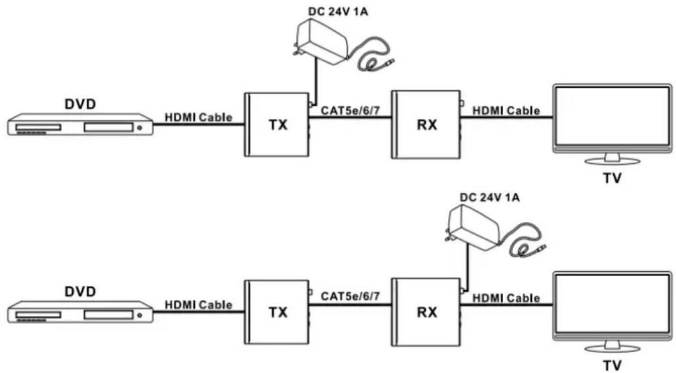
- POE(Power Over Ethernet)function support, either TX or RX powered 24V@1A,another don't need power form the DC jack.
- Full HD support: 1080p@60Hz@24/36/48bit/pixels.
- Supports USB 2.0 control.
- Supports external Bi-Directional SPDIF IN/OUT and available for multichannel audio.
- Supports stereo audio with PCM 2CH.
- Transfer Bidirectional Infrared control signal together with the HDMI signal.
- Transfer Bidirectional RS232 control signal together with the HDMI signal.
- Transfer Bidirectional Ethernet signal together with the HDMI signal.
3. Package
- HDMI USB KVM Extender Transmitter ---- 1PCS
- HDMI USB KVM Extender Receiver ---- 1PCS
- Wideband IR Tx 2PCS
- Wideband IR Rx 2PCS
- 24V/1A DC power adaptor 1PCS
- Operation Manual 1PCS
- Phoenix male jack----2PCS
- Mounting ears----4PCS
4. Specifications
| 1. Video Bandwidth | 340MHz/10.2Gbps |
| 2. Transmitter | |
| Input Ports | 1x HDMI, 1xLAN, 1xUSB-H,1xIR in, 1x Audio in, 1xRS232,1xOptical (Spdif in), |
| Output Ports | 1xIR out, 1xOptical (Spdif out),1xHDBaseT OUT, 2xUSB-D |
| 3. Receiver | ||
| Input Ports | 1xIR in, 1xOptical (Spdif in), 1xHDBaseT IN, 1xUSB-H | |
| Output Ports | 1x HDMI, 1xLAN, 2xUSB, 1xIR out, 1x Audio out, 1xRS232,1xOptical (Spdif out), DC 24V 1A | |
| 4. | Power Supply | ± 8kV (air-gap discharge) |
| 5. | ESD Protection | ± 4kV (contact discharge) |
| Human Body Model: | ||
| 6. | Dimensions (mm) | 160(W) X 97 (D) X 28 (H) |
| 7. | Weight | 450g/TX, 450g/RX |
| 8. | Operating Temperature | 0°C ~ 40°C / 32°F ~ 104°F |
| 9. | Storage Temperature | -20°C ~ 60°C / -4°F ~ 140°F |
| 10. | Relative Humidity | 20~90% RH (Non-condensing) |
| 11. | Power Consumption (Max) | 12W |
5. Operation controls and Functions
5.1 Transmitter Front Panel
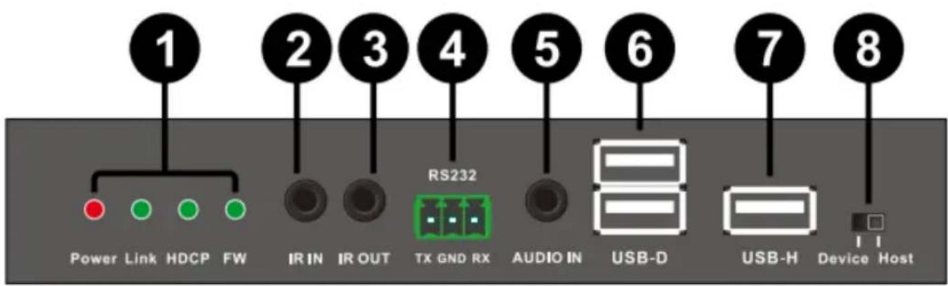
1. Indicator LED:
Power LED: illuminates when power has been supplied to the unit.
Link LED: The connection status indicating lamp.
- Illuminate: The Transmitter and Receiver is good connections.
- Flashing: The Transmitter and Receiver is poor connections.
Dark: The Transmitter and Receiver is no connections.
HDCP LED: The HDCP status indicating lamp.
▶ Illuminate: The HDMI signal with HDCP.
- Flashing: The HDMI signal without HDCP.
Dark: No HDMI signal.
FW LED: Light is flashing on behalf of the unit work normally
- IR IN: Chanel 1 IR Receiver. Connect with Wideband IR Rx.
- IR OUT: Chanel 2 IR Transmitter. Connect with Wideband IR Tx.
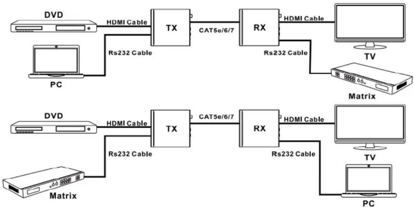
- RS232 TX/RX: Connect to a PC or Laptop with 3-pin Relay cable for the transmission of RS-232 commands.
- AUDIO IN: Connect to a PC or Laptop stereo output port via 3.5mm audio cable.
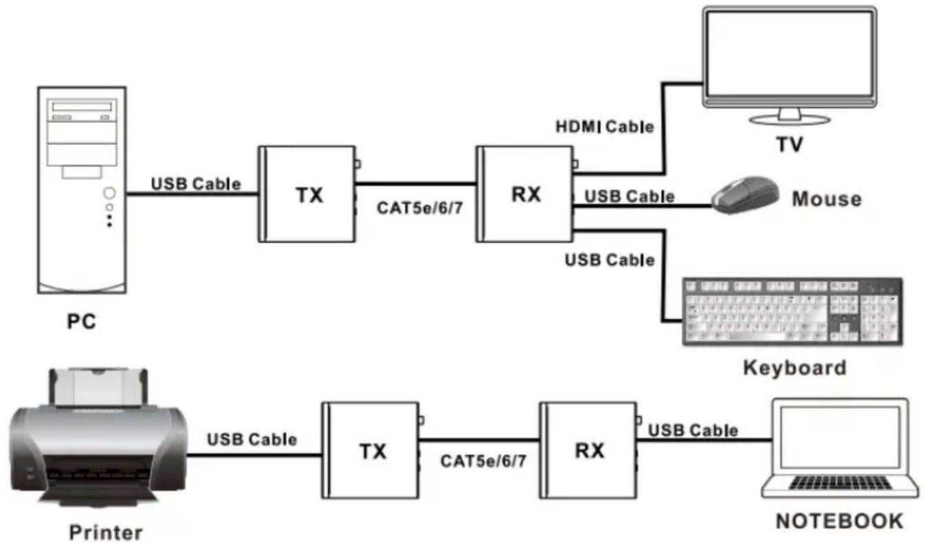
- USB-D: Connect to USB peripheral devices such as printer, keyboard, mouse, flash driver or ...etc.
- USB-H: Connect from PC or Laptop for data transmit to or control from the Receiver's USB-D slots.
- USB-H/USB-D SELECT: Select USB host or USB device.
Note: If the unit work to change the state, required again to power
supply.
5.2 Transmitter Rear Panel
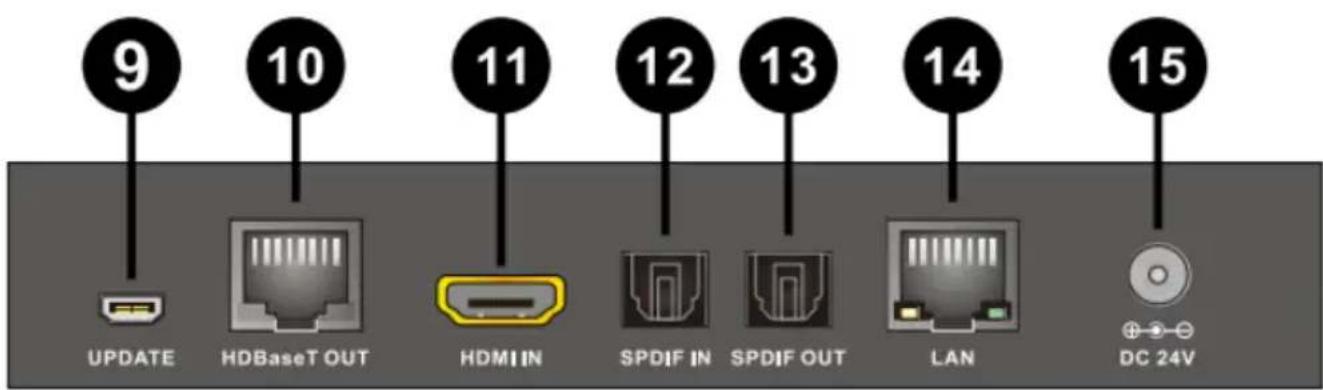
- UPDATE: Reserved for manufacturer use only.
- HDBaseT OUT: Standard HDBaseT signal output port. Connect HDBaseT receiver with a Cat5e/6/7 cable.
- HDMI IN: This slot is where you connect the HDMI source.
- SPDIF IN(Optical in): Connect to audio source equipment such as DVD or Blu-ray player for audio signal sending to Receiver's SPDIF OUT(Optical out).
- SPDIF OUT(Optical out): Connect to speaker with coaxial input for audio signal output from Receiver's SPDIF IN(Optical in).
- LAN: This slot provide Internet signal from receiver or to receiver.
- DC IN: Plug the 24V DC power supply into the unit.
5.3 Receiver Front Panel
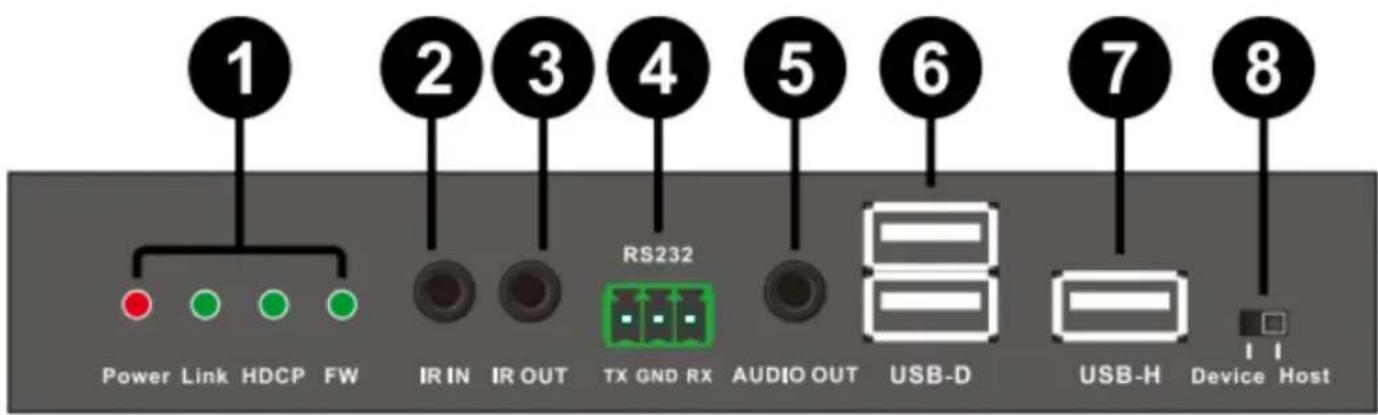
1. Indicator LED:
Power LED: illuminates when power has been supplied to the unit. Link LED: The connection status indicating lamp.
- Illuminate: The Transmitter and Receiver is good connections.
- Flashing: The Transmitter and Receiver is poor connections.
Dark: The Transmitter and Receiver is no connections.
HDCP LED: The HDCP status indicating lamp.
▶ Illuminate: The HDMI signal with HDCP.
➢ Flashing: The HDMI signal without HDCP.
Dark: No HDMI signal.
FW LED: Light is flashing on behalf of the unit work normally
- IR IN: Chanel 1 IR Receiver. Connect with Wideband IR Rx.
- IR OUT: Chanel 2 IR Transmitter. Connect with Wideband IR Tx.
- RS232 TX/RX: Connect to the devices (project...etc) that is to be controlled via 3-pin Relay cable by RS-232 commands.
- AUDIO OUT: Connect to speaker via 3.5mm audio cable.
- USB-D: Connect to USB peripheral devices such as printer, keyboard, mouse, flash driver or ...etc.
- USB-H: Connect from PC or Laptop for data transmit to or control from the Receiver's USB-D slots.
- USB-H/USB-D SELECT: Select USB host or USB device.
Note: If the unit work to change the state, required again to power supply.
5.4 Receiver Rear Panel
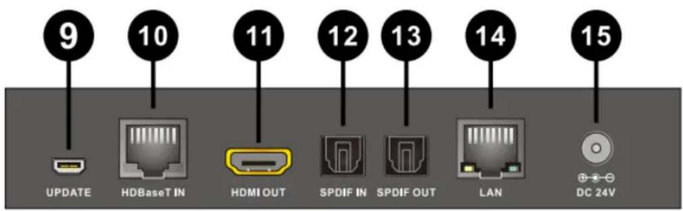
- UPDATE: Reserved for manufacturer use only.
- HDBaseT IN: Standard HDBaseT signal output port. Connect HDBaseT Transmitter with a Cat5e/6/7 cable.
- HDMI OUT: This slot is where you connect the a HDMI equipped TV/monitor.
- SPDIF IN(Optical in): Connect to audio source equipment such as DVD or Blu-ray player for audio signal sending to Transmitter's SPDIF OUT(Optical out).
- SPDIF OUT(Optical out): Connect to speaker with coaxial input for audio signal output from Transmitter's SPDIF IN(Optical in).
- LAN: This slot provide Internet signal from receiver or to receiver.
- DC IN: Plug the 24V DC power supply into the unit.
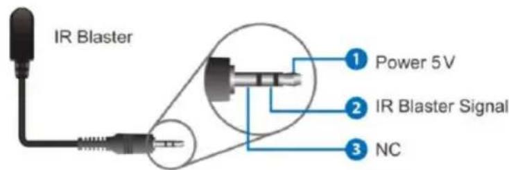
5.5 IR Cable Pin Assignments

6. Connection Diagram
6.1 POE(Power Over Ethernet) Application Example
flowchart
graph LR
    A["TV"] -->|HDMI Cable| B["TX"]
    B -->|CAT5e/6/7| C["RX"]
    C -->|HDMI Cable| D["TV"]
    E["DC 24V 1A"] --> B
    F["DC 24V 1A"] --> C
    G["TV"] -->|HDMI Cable| H["TX"]
    H -->|CAT5e/6/7| I["RX"]
    I -->|HDMI Cable| J["TV"]
6.2 Bidirectional Infrared control Application Example

flowchart
graph LR
    A["TV"] -->|TX 1| B["TX"]
    B -->|TX 2| C["Monitor"]
    D["DVD"] -->|HDMI Cable| E["TX"]
    E -->|CAT5e/6/7| F["RX"]
    F -->|HDMI Cable| G["TV"]
    H["TV Remote"] --> I["TX 1"]
    J["RX 2"] --> K["TX 1"]
    L["DVD Remote"] --> M["TX 2"]
    N["RX 1"] --> O["TX 1"]
6.3 Bidirectional RS232 control Application Example
flowchart
graph LR
    subgraph Top_1
        A["PC"] -->|HDMI Cable| B["TX"]
        B -->|CAT5e/6/7| C["RX"]
        C -->|HDMI Cable| D["TV"]
        C -->|Rs232 Cable| E["Matrix"]
    end
    subgraph Bottom_2
        F["PC"] -->|HDMI Cable| G["TX"]
        G -->|CAT5e/6/7| H["RX"]
        H -->|HDMI Cable| I["TV"]
        H -->|Rs232 Cable| J["Matrix"]
    end
6.4 Bidirectional Ethernet signal Application Example

flowchart
graph LR
    subgraph Top_1
        A["PC"] -->|HDMI Cable| B["TX"]
        B -->|CAT5e/6/7| C["RX"]
        C -->|HDMI Cable| D["Switch/Router"]
        C -->|UTP Cable| E["PC"]
    end
    subgraph Bottom_2
        F["PC"] -->|HDMI Cable| G["TX"]
        G -->|CAT5e/6/7| H["RX"]
        H -->|HDMI Cable| I["Switch/Router"]
        H -->|UTP Cable| J["PC"]
    end
6.5 USB control Application Example
flowchart
graph LR
    PC["PC"] -->|USB Cable| TX1["TX"]
    TX1 -->|CAT5e/6/7| RX1["RX"]
    RX1 -->|USB Cable| Mouse["Mouse"]
    RX1 -->|USB Cable| Keyboard["Keyboard"]
    Mouse --> TV["TV"]
    Keyboard --> NOTEBOOK["NOTEBOOK"]

    Printer["Printer"] -->|USB Cable| TX2["TX"]
    TX2 -->|CAT5e/6/7| RX2["RX"]
    RX2 -->|USB Cable| Notebook["NOTEBOOK"]
6.6 Digital Audio bidirectional transmission Application Example

flowchart
graph LR
    A["DVD"] -->|SPDIF Cable| B["TX"]
    B -->|CAT5e/6/7| C["RX"]
    C -->|SPDIF Cable| D["Amplifier"]
    E["Amplifier"] -->|SPDIF Cable| F["TX"]
    F -->|CAT5e/6/7| G["RX"]
    G -->|SPDIF Cable| H["DVD"]
7. Application Example

flowchart
graph TD
    A["Transmitter"] --> B["Power Supply"]
    B --> C["PC"]
    C --> D["Internet Modem or Router"]
    D --> E["DVD or Blu-ray Player"]
    E --> F["IR TX"]
    E --> G["IR RX"]
    H["Receiver"] --> I["Optical fiber"]
    I --> J["HDMI"]
    J --> K["TV"]
    K --> L["IR TX"]
    M["Monitor"] --> N["Amplifier"]
    N --> O["NoteBOOK"]
    P["Mouse"] --> Q["Keyboard"]
    R["Power Supply"] --> S["Power Care"]

Comprehensive
80 Little Falls Road, Fairfield, NJ 07004 Phone: 800.526.0242 | Fax: 201.814.0510 www.ComprehensiveCo.com
- HDBaseT 2.0 Extender up to 330ft with USB - Transmitter & Receiver
- Caution:
- Direct interconnection method
- Introduction
- Features
- Package
- Specifications
- Operation controls and Functions
- Transmitter Front Panel
- Indicator LED:
- Transmitter Rear Panel
- Receiver Front Panel
- Receiver Rear Panel
- IR Cable Pin Assignments
- Connection Diagram
- POE(Power Over Ethernet) Application Example
- Bidirectional Infrared control Application Example
- Bidirectional RS232 control Application Example
- Bidirectional Ethernet signal Application Example
- USB control Application Example
- Digital Audio bidirectional transmission Application Example
- Application Example
- Comprehensive
Brand : Comprehensive
Model : CHE-HDBT300U
Category : Receiver