
SW-UF24P2GV-062 - Switch Mach Power - Free user manual and instructions
Find the device manual for free SW-UF24P2GV-062 Mach Power in PDF.


| Product Type | 24-Port PoE Switch with 2 Gigabit Uplink |
| Model | SW-UF24P2GV-062 |
| Dimensions (L x W x H) | 440 x 292 x 43.6 mm |
| Weight | 4.25 kg |
| Power Supply | Built-in, AC 96-264V |
| PoE Budget | 250W total, up to 30W per port |
| PoE Standard | IEEE 802.3af/at |
| Network Ports | 24 x 10/100Mbps Downlink RJ45, 2 x 10/100/1000Mbps Uplink RJ45 |
| Transmission Distance | Downlink: 100m (250m with VLAN enabled), Uplink: 100m |
| Network Standards | IEEE 802.3, 802.3u, 802.3ab, 802.3z, 802.3af/at |
| Switching Capacity | 6.5472 Mpps |
| MAC Address Table | 16K |
| Surge Protection | 2KV common mode, 0.5KV differential mode (IEC61000-4-5) |
| Electrostatic Protection | Contact ±4KV, Air ±4KV (IEC61000-4-2) |
| Operating Temperature | 0°C to 55°C |
| Storage Temperature | -40°C to 85°C |
| Humidity | 0-95% non-condensing |
| Housing Material | Galvanized steel |
| Reset Button | Yes, whole device restart |
| VLAN Feature | Port-based VLAN for enhanced security, extends downlink distance to 250m |
| Mounting | Rack-mount ears for cabinet or wall installation |
Frequently Asked Questions - SW-UF24P2GV-062 Mach Power
User questions about SW-UF24P2GV-062 Mach Power
0 question about this device. Answer the ones you know or ask your own.
Ask a new question about this device
Download the instructions for your Switch in PDF format for free! Find your manual SW-UF24P2GV-062 - Mach Power and take your electronic device back in hand. On this page are published all the documents necessary for the use of your device. SW-UF24P2GV-062 by Mach Power.
USER MANUAL SW-UF24P2GV-062 Mach Power
-
Fuse: Max 10A
-
Ground Connection
-
Waiting Content
-
Power Switch: Turn on with power, Turn off no power
-
Input: AC 96-264V
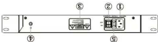
Rear panel
- Power indicator: Red Light on with power; Light off; no power
Green LED blinks: data transfer
Green LED off link down
- Link/ Act indicator: Green LED on: link up
Light off: when device is not detected or not powered
-
Pose indicator: Yellow Light on: when device is powered
-
Reset Button: Whole machine will restart while press button
Turn off VLAN button: indicator off and VLAN function stops
- YUAN Button: Turn on YUAN Button; Indicator on and YUAN function starts
14h/ADSL
-
Gigabit Uplink RJ45 Port: Transfer data from Port ports to other devices |NVR/Sw-
-
Downlink RJ45 port: Transfer data from other IP devices to the switch
-
Rack-mounting ears: Cabinets for product installation or wall installation

Front panel
L
Balvanized housing for stable and durable working life
Easy and convenient to use, play & play, no need to confiure
Built-in 250W power supply
Resistant function helps master to reset wholly
Surge protection: 2kV
Excellent anti-thunder, anti-state and anti-inference ability
Transmission distance max up to 250 meters when VLA is enabled
Port based VILAN for Enhanced Security
PoE data & power transmission distance up to 100 meters
250 watts POE budget
6igabit uplink RU-45 port: 2 x 10/100/1000Mbps
Provide 15.4W or 30W power to powered devices
24 Ports support 48V-56VDC power to PoE powered devices
Support LEE802.3x full-duplex low control; support Auto MDI/MDIX
Comply with IEE802.3, IEE802.3u, IEE802.3sf/at standards
Features
State via Internet
With data and power over Ethernet from one unit, the SW-UP24P26V-062 reduces calling requirements and eliminates the need for dedicated electrical outlets on the wall, ceiling or any unreachable place. A wire that carries both data and power can lower the installation costs, simply the installation effort and eliminate the need for electricians or expansion circles. Pranding 24 PE interfacies, the SW-UP24P26V-062 is ideal for small businesses and workgroups requiring depaying the PE for the wireless access points, LP-based surveillance IP phones in any places easily, efficiently and cost-effectively.
The SW-UF24P26V-062 provides 24 ports 10/100Mbps IEE8E023cal/Port over demand of sufficient PE power for network applications. The SW-UF24P26V-062 is an ideal solution for securing 1P surveillance infrastructure. It provides both 8023cal/Port functions along with 24 x 10/100Mbps ports listening 15.4 hours, 8023cal/Portes 8023cal/Port in RL-45 interfaces and extra 2-Giagonal wireless ports with 8023cal/Portes 8023cal/Port in RL-45 interfaces and extra 2-Giagonal wireless port in 10/100Mbps/Port RJ-45 to keep a cache connection with another switch or NWR. For instance, one 24 Channels NWR and 74 PE IP cameras as a kit for the administrators to centrally and efficiently manage the surveillance system in the local LAN and the remote
Overview
Quick Setup Guide
Step1: Begin with all input/output devices turned off with power cables removed
Step2: Connect RJ-45 port of PoE cameras with Downlink RJ-45 port of PoE switches in standard Cat 5e/6 cables
Step3: Connect with Uplink RJ-45 port of PoE switches with RJ-45 port of NVR or computer or other devices in standard Cat 5e/6 cables
Step4: Input AC power cord into power socket of PoE switch
Step5: Make sure above connection is properly finished, then turn on power
VLAN Introduction
At present, applications of Ethernet switch is very wide. To satisfy the needs of various customers, it is urgent for network services to solve the problems of broadcast domains, bandwidth and security, so a new kind of technology of VLAN emerged. Each DOWNLINK RJ-45 port and UPLINK RJ-45 ports form a separate workstation respectively. In the same VLAN workstation, regardless of which switch they are actually connected to, the communication between them is as if they were on a separate switch. Broadcasts in the same VLAN can only be heard by members of the VLAN, but not in other VLANs, which can control the generation of unwanted broadcast storms. At the same me, if there is no routing, different VLANs cannot communicate with each other, which increases the security of different departments in the enterprise network. When the VLAN mode is enabled, the data cannot be forwarded among DOWNLINK RJ-45 ports, but DOWNLINK RJ-45 ports and UPLINK RJ-45 ports can communicate with each other. The bandwidth of DOWNLINK RJ-45 ports is forced to 10Mbps mode to adapt to the long distance transmission of max 250meters. The bandwidth of UPLINK RJ-45 port is 1000Mbps, which keeps a cascade connecon with another switch or NVR.
Note:
When you turn on VLAN button, please press reset button or reboot the power of the device, than VLAN mode is enabled.
3
Technical Specification
| MODEL | SW-UF24P2GV-062 | |
| Product name | 24 ports 10/100Mbps IEEE 802.3af/at PoE switch | |
| Power Supply | Power Supply mode | Built-in power supply |
| Voltage range | AC 96~264V | |
| Power consumption | The device <10W | |
| PoE power supply ≤250W | ||
| Network port parameter | Network Port | Ethernet downlink RJ45 port : 24 x 10/100Mbps |
| Gigabit uplink RJ45 port: 2 x 10/100/1000Mbps | ||
| Transmission distance | Downlink port: 100m | |
| Uplink port: 100m | ||
| Transmission medium | Downlink port: Cat5e/6 standard cable | |
| Uplink port: Cat5e/6 standard cable | ||
| PoE standard | IEEE802.3 af/at standard | |
| PoE power supply mode | End span method | |
| PoE power supply wallage | Each port ≤30W | |
| Whole device ≤250W | ||
| Network switch specification | Network standards | IEEE802.3, IEEE802.3ab, IEEE802.3ad |
| IEEE802.3u, IEEE802.3az | ||
| IEEE802.3z | ||
| Swap mode | Store and forward | |
| Data-caching mechanism | 4M | |
| MAC address list | 16K | |
| Throughput | 6.5472Mbps | |
| Indicator | Power indicator | Red led on: power on |
| Uplink gigabit port | Green led on: link up | |
| Green led off: link down | ||
| Green led blinks: data transfer | ||
| PoE indicator | 24 PoE indicator [yellow] | |
| PoE network port indicator | 24 port indicators blink while data transfer | |
How to make a network cable
To create a network cable, you will first need the equipment listed below.
- Cat5e, Cat6, or Cat7 cable
- RJ-45 connectors
- Crimping tool

T568A
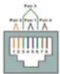
T568B
The wire sequence of RJ45 connector must comply with internaonal standard of EIA/TIA 568A or EIA/TIA 568B.
| 1 | 2 | 3 | 4 | 5 | 6 | 7 | 8 | |
| T568A | white green | green | white orange | blue | white blue | orange | white brown | brown |
| T568B | white orange | orange | white green | blue | white blue | green | white brown | brown |
- We recommend stripping at least a half of an inch off the cable to expose the inner wires.
- Separate the wires within the cable after the network cable jacket has been removed so that they can be put into the RJ-45 connector
- The CAT5 twisted-pair cable consist of four twisted wires, each color coded; 8 wires must be correctly lined as the standards of EIA/TIA 568A or EIA/TIA568B
- Cut thread residue and leave 1.5cm wire exposed outside the insulating layer and ensure 8 wire are straighten and neat.
- Place the cable into the RJ-45 connector and use the crimping tool to attach the connector.
- Repeat above steps for the other end of the cable; the wire sequence of both ends of the cable is suggested to be identical.
- Make sure to test the cables before installing them once both ends of the cable have been completed.
Note:
- All RJ-45 Ports of this device support Auto MDI/MDIX, so the different wire sequence of both enads of the cable is allowed.
| Button | Reset button | Press the reset button and the device restarts |
| Protection level | Surge protection | 2KV [common mode], 10/700us IEC61000-4-5 |
| 0.5KV [differential mode], 10/700us IEC61000-4-5 | ||
| Electrostatic protection | Contact Discharge: +4KV | |
| Air Discharge: +4KV | ||
| Standard:IEC61000-4-2 | ||
| Reliability | Mean time btw failures | >50.000h |
| Mechanical | Dimension (mm) | 440L x 292W x 43.6H |
| Housing | Galvanized | |
| Body color | Black | |
| Net weight | 4.25kg | |
| Environmental | Operating temperature | 0°C~ 55°C |
| Storage temperature | -40°C~ 85°C | |
| Relative Humidity | 0~ 95% (non-condensing) |

Brand : Mach Power
Model : SW-UF24P2GV-062
Category : Switch