
STNet Switch - Receiver SoundTube - Free user manual and instructions
Find the device manual for free STNet Switch SoundTube in PDF.


| Product Type | Audio/Video Receiver with Network Switch |
| Brand | SoundTube |
| Model | STNet Switch |
| Dimensions (W x H x D) | 17 x 3.5 x 12 inches (43 x 8.9 x 30.5 cm) |
| Weight | 12.5 lbs (5.7 kg) |
| Power Supply | AC 120V/60Hz, 400W max |
| Audio Channels | 7.2 channels |
| Network Switch Ports | 4 x Gigabit Ethernet |
| HDMI Inputs/Outputs | 4 inputs / 1 output (HDCP 2.2) |
| Bluetooth | Yes, version 5.0 |
| Wi-Fi | Dual-band 802.11ac |
| Supported Audio Formats | Dolby Atmos, DTS:X, PCM |
| Remote Control | Included (IR) |
| Maintenance & Cleaning | Wipe with dry cloth; do not use liquids or solvents |
| Safety | Do not expose to moisture; unplug during storms |
| Spare Parts & Repairability | Contact SoundTube support for parts; user-replaceable fuse |
| General Information | Free user manual available in PDF at notice-facile.com |
Frequently Asked Questions - STNet Switch SoundTube
User questions about STNet Switch SoundTube
0 question about this device. Answer the ones you know or ask your own.
Ask a new question about this device
Download the instructions for your Receiver in PDF format for free! Find your manual STNet Switch - SoundTube and take your electronic device back in hand. On this page are published all the documents necessary for the use of your device. STNet Switch by SoundTube.
USER MANUAL STNet Switch SoundTube
Please read the following instructions carefully before installing your SoundTube ® amplifier. If you have any questions regarding installation that are not answered in the following directions, please contact your local sound contractor or the SoundTube ® /MSE Audio ® technical support team. Contact information can be found on the back of the manual.
FCC Notice
This device complies with Part 15 of the FCC Rules. Operation is subject to the following two conditions: (1) this device may not cause harmful interference, and (2) this device must accept any interference received, including interference that may cause undesired operation.
Changes or modifications not expressly approved by the party responsible for compliance could void the user's authority to operate the equipment.
This equipment has been tested and found to comply with the limits for a Class B digital device, pursuant to part 15 of the FCC Rules. These limits are designed to provide reasonable protection against harmful interference in a residential installation. This equipment generates uses and can radiate radio frequency energy and, if not installed and used in accordance with the instructions, may cause harmful interference to radio communications. However, there is no guarantee that interference will not occur in a particular installation. If this equipment does cause harmful interference to radio or television reception, which can be determined by turning the equipment off and on, the user is encouraged to try to correct the interference by one or more of the following measures: (1) Reorient or relocate the receiving antenna. (2) Increase the separation between the equipment and receiver. (3) Connect the equipment into an outlet on a circuit different from that to which the receiver is connected. (4) Consult the dealer or an experienced radio/TV technician for help.
Under Industry Canada regulations, this radio transmitter may only operate using an antenna of a type and maximum (or lesser) gain approved for the transmitter by Industry Canada. To reduce potential radio interference to other users, the antenna type and its gain should be so chosen that the equivalent isotropically radiated power (e.i.r.p.) is not more than that necessary for successful communication.
To satisfy FCC RF exposure requirements, a separation distance of 20 cm or more should be maintained between the antenna of this device and persons during device operation. To ensure compliance, operations at closer than this distance are not recommended.
This device complies with Industry Canada licence-exempt RSS standard(s). Operation is subject to the following two conditions: (1) this device may not cause interference, and (2) this device must accept any interference, including interference that may cause undesired operation of the device.
Information for the OEMs and Integrators- This device is intended for OEM integrators only. Please see the full Grant of Equipment document for restrictions. This device must be operated and used with a locally approved access point.
Label Information to the End User by the OEM or Integrator- If the FCC ID of this module is not visible when it is installed inside another device, the outside of the device into which the module is installed must be labeled with “Contains FCC ID: SU3RM2400A” in a visible area.
Important Safety Instructions
-
Read these instructions.
-
Keep these instructions.
-
Heed all warnings.
-
Follow all instructions.
-
Do not use this apparatus near water.
-
Clean only with a dry cloth.
-
Do not block any ventilation openings. Install in accordance with the manufacturer's instructions.
-
Do not install near any heat sources such as radiators, heat registers, stoves, or other apparatus (including amplifiers) that produce heat.
-
Protect the power cord from being walked on or pinched particularly at plugs, convenience receptacles, and the point where they exit from the apparatus.
-
Only use attachments/accessories specified by SoundTube.
-
Unplug this apparatus during lightning storms or when unused for long periods of time.
-
Refer all servicing to qualified service personnel. Servicing is required when the apparatus has been damaged in any way, such as power-supply cord or plug is damaged, liquid has been spilled or objects have fallen into the apparatus, the apparatus has been exposed to rain or moisture, does not operate normally, or has been dropped.
-
This apparatus shall be connected to a mains socket outlet with a protective earthing connection.
-
When permanently connected, on all-pole mains switch with a contact separation of at least 3mm in each pole shall be incorporated in the electrical installation of the building.
-
If rack mounting, provide adequate ventilation. Equipment may be located above or below this apparatus but some equipment (like large power amplifiers) may cause an unacceptable amount of hum or may generate too much heat and degrade the performance of this apparatus.
-
This apparatus may be installed in an industry standard equipment rack. Use screws through all mounting holes to provide the best support.
WARNING -- TO REDUCE THE RISK OF FIRE OR ELECTRIC SHOCK, DO NOT EXPOSE THIS APPARATUS TO RAIN OR MOISTURE.
STNet Overview
The STNet-Switch is an audio grade 16 port, proprietary 40w PoE, network Switch. The STNet-Switch allows users to connect up to 16 SoundTube IPD speakers via Cat-5 or 6 and power them using the internal 40w PoE. Expansion beyond 16 speakers can be done one of four ways; with additional STNet-Switches, using a PoE+ or PoE switch or using a non-powered switch with local power. The Switch has 2 non-powered gigabit ports for high speed expansion.
Note: The WAN and I/O ports are not used in Dante systems.
The Switch has a built in DHCP server for IP assignment which it uses to identify each end point. If you do not need the DHCP server or are using multiple STNet switches, it can be disabled. (See instructions below).
The STNet Switch and Power Supply can be table top or rack mounted.
Rack Mounting
To Rack mount the STNet Switch and Power Supply attach the rack mount ears to the left and right sides. The front of the ears should be even with the front panel.
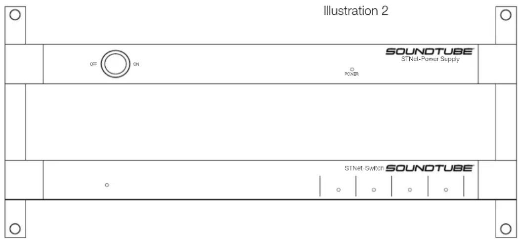
- Line up the rack. See Illustration 2.
- Using 8 screws (included in the box) fasten the ears to the side panels.
- Follow the directions that came with the rack to mount the STNet-Switch and Power Supply.
Table Top
The STNet-Switch and Power Supply each come with 4 rubber pads with two sided adhesive already attached. Remove the protective film from the pads and attach one to each corner. See illustration 3.
Illustration 3
Bottom View

Connections
- Make sure the front panel rocker switch on the front of the Power Supply is set to off.
- Connect the 6 pin power cable between the Power Supply and the Switch. Push the cable all the way in until you feel it lock.
- Connect the AC power cable to the back of the Power Supply and to a 110/220v power source.
- Connect a computer to a LAN port on the switch.
Note: Do not connect the speakers to the ST-Net switch at this time.
Running the Application
Load the SoundTube DNA Controller Application. It can be found on the SoundTube website.
Start the application under Programs/SoundTube/DNA Control. Before the application can be run, it is necessary to configure a network adapter in the PC to allow it to communicate with Dante devices.
Setting up the PC Network Adapter
DNA Control has to have access to the Dante network through a network adapter. From the main DNA Control page click on the computer icon and select the network adapter connected to the Dante Network.
The program can be run with or without a router. If there is no router present DNA Control will assign IP addresses to the speakers. When used with the STNet Switch the IP addresses will be given out automatically by the switch. This feature can be turned off using the Control Center software (CobraNet Control Center) by changing the switch from a Master to a Slave. See Section ???The IP address can also be given manually (known as a static IP address) using Dante Controller. See the Dante Controller manual for instructions on setting up static IP addresses.
Turn the power switch to the on position on the STNet-Power Supply. The Switch should boot up in approximately 45 seconds. Once the 4 indicators on the front panel are lit green the Switch is ready. The STNet Switch should be visible on the screen.
Connect the speakers one at a time to the STNet-Switch using a Cat-5 or Cat-6 cable with RJ-45 connectors on each side.
The speakers will populate the main screen (See Fig ?) of the Control Center software as they are recognized. As each speaker comes up click on it and use the location field to identify the speaker. For example "Left Front in ballroom 1". To save the name go Save Preset and save it to the default or 01 location.
The Main Form
The STNet-Switch is an audio grade 16 port, proprietary 40w PoE, network Switch. The STNet-Switch allows users to connect up to 16 SoundTube IPD speakers via Cat-5 or 6 and power them using the internal 40w PoE. Expansion beyond 16 speakers can be done one of four ways; with additional STNet-Switches, using a PoE+ or PoE switch or using a non-powered switch with local power. The Switch has 2 non-powered gigabit ports for high speed expansion.
Note: The WAN and I/O ports are not used in Dante systems.
The Switch has a built in DHCP server for IP assignment which it uses to identify each end point. If you do not need the DHCP server or are using multiple STNet switches, it can be disabled. (See instructions below).
The STNet Switch and Power Supply can be table top or rack mounted.
Main Form Functions

Figure 1 Initial Main Window
When a device is first detected, it will always show a yellow icon. Once initial contact has been made with it, the icon will turn green and stay green for as long as the device remains active. If the device is turned off or stops responding, it will remain in the list but the icon with turn red. As the device list populates, the device list fields will fill. The device list shows the devices MAC address, current IP address, Device name and location
It should be noted there is a delay between turning on a device, and its consequent detection and appearance on the device list with a yellow icon. This delay may be several seconds.
Once devices appear in the device list, they may be selected. Only one device may be selected at a time. To select a device, click on it in the device list. A double click will bring us the device configuration menu for that speaker.
Speaker Configurations Page

Figure 2 Main Window w/ Devices
Fig 2 Speaker configuration page
Note: the Identify button is not active
Each IPD speaker on the STNet can be individually set up for gain, EQ, Hi and Low pass, and delay. The DNA Device Control page (fig ?) is used to change these settings
Input/Output Gain Controls
Input and output gain can be set using the slide control or values can be input directly. The range is -100 to +12dB. The Output gain control has the option of muting the speaker or inverting its polarity. Note: Do not set the level lower than -25dB. Doing so will give you incorrect readings on the speaker monitoring fault detection circuit
8 Band Parametric Equalizer
Each speaker has an 8 band parametric equalizer. The settings on each band are frequency, gain and bandwidth. To access individual bands uncheck the Bypass box. All EQ's can be temporarily bypassed by checking the Bypass EQ box or reset to the default values by pressing the Reset EQ button. Values can be input directly or adjusted using the slide bars.
Pink Noise
Each speaker has an 8 band parametric equalizer. The settings on each band are frequency, gain and bandwidth. To access individual bands uncheck the Bypass box. All EQ's can be temporarily bypassed by checking the Bypass EQ box or reset to the default values by pressing the Reset EQ button. Values can be input directly or adjusted using the slide bars.
Status Box
The Status box shows the status of the amplifier, board temperature and woofer and tweeter voice coils. Green means they are operating within normal parameters. Red indicates a failure or abnormal condition. If there is a red indicator try resetting the speaker. If it does not clear it might need to be repaired or replaced.
Amp Page
IPD4 Page


Brand : SoundTube
Model : STNet Switch
Category : Receiver