
V-9983 - Blender Valcom - Free user manual and instructions
Find the device manual for free V-9983 Valcom in PDF.


| Product Type | Blender |
| Brand | Valcom |
| Model | V-9983 |
| Dimensions (H x W x D) | Approx. 400 x 180 x 180 mm |
| Weight | Approx. 2.5 kg |
| Power Consumption | 500 W |
| Jar Capacity | 1.5 L |
| Jar Material | Glass |
| Number of Speed Settings | 2 speeds + Pulse |
| Blade Material | Stainless Steel |
| Dishwasher Safe Parts | Jar, lid, and blade assembly |
| Safety Features | Non-slip feet, safety lock mechanism |
| Power Cord Length | Approx. 1.2 m |
| Voltage / Frequency | 220-240 V ~ 50/60 Hz |
| Cleaning Instructions | Detachable parts dishwasher safe; wipe base with damp cloth |
| Spare Parts Availability | Blade, jar, lid, sealing ring |
| Warranty | 2 years |
Frequently Asked Questions - V-9983 Valcom
User questions about V-9983 Valcom
0 question about this device. Answer the ones you know or ask your own.
Ask a new question about this device
Download the instructions for your Blender in PDF format for free! Find your manual V-9983 - Valcom and take your electronic device back in hand. On this page are published all the documents necessary for the use of your device. V-9983 by Valcom.
USER MANUAL V-9983 Valcom
V-9983 2 CHANNEL MODULAR PRE-AMP/MIXER V-9984 REMOTE INPUT MODULE V-9985 4 CHANNEL MODULAR PRE-AMP/MIXER
INTRODUCTION
These instructions contain the specifications and guidelines necessary to install, operate, and maintain the Modular Pre-Amp/Mixer. The unit provides connections for up to 4 remote input modules. The mixer consists of a V-9983 Main Control Module and a V-9984 Remote Input Module.
The Modular Pre-Amp Mixer is used with Valcom distributed amplified one way paging systems providing additional audio source inputs.
The V-9985 provides active mixing for 1 balanced microphone and 2 auxiliary inputs. Also supplied is an additional audio input (building page) with an override feature. Up to 3 additional Remote Input Modules (V-9984) may be connected to the Main Control Module. Each Remote Input Module adds 1 Balanced Microphone and 1 Auxiliary input.
Applications
- Valcom, Inc. Distributed Amplified One-Way Paging Systems. Refer to Figure 1 for a block diagram of a typical installation.
Features
Main Control Module V-9983
• High impedance auxiliary input
• Volume control for auxiliary input
• 3.5mm stereo mini jack for auxiliary input
• Master volume control
- Up to (4) four remote mixer modules may be connected
- Separate outputs for Horns and Speakers
- Page port connection (Building Page) with override option switch
- Remote Volume Control Connection
• LED Signal Meter
- Built-in Compressor, option dip switch controlled
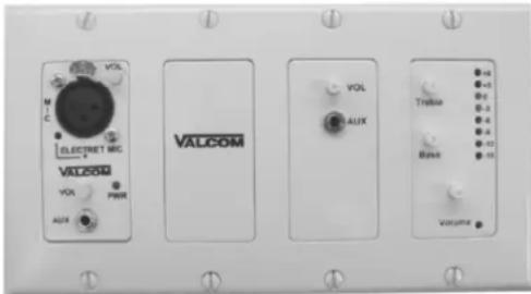
• Power "ON" indicator
- Mounts in 3 gang electrical box
MAIN CONTROL MODULE WITH REMOTE INPUT MODULE
Remote Input Module V-9984
• Balanced microphone
- XLR Mic. Connection
- Phantom power for electret microphones (Switch controlled)
- Phantom power "ON" indicator
• High impedance auxiliary input
• Volume control for auxiliary input
• 3.5mm stereo mini jack for auxiliary input
• Power "ON" indicator
- Mounts in single gang electrical box
- Connects to Main Control Module with 2 pair 24AWG station cable
- Screw terminals for distribution connections
Dimensions
Main Control Module
- 5"W x 4.25"H x 2"D
(12.7cm W x 10.8cm D x 5.08cm H)
• 4 lbs. (1.5Kg)
Remote Input Module
• 1.64W x 4.25"H x 2"D
(4.17cm W x 10.8cm D x 5.08cm H)
• .25 lbs. (0.1Kg)
Specifications Outputs
• Main Output: -10 dBm nominal, 100 Ohms
• Frequency Response: 2Hz to 20kHz ± 1dB
• Horn Output: -10 dBm nominal, 100 Ohms
- Frequency Response 20Hz to 20kHz ± 1dB (12 dB/Octave High pass at 300Hz)
Tone Controls
• Bass (50 Hz) boost or cut up to 12 dB
- Treble (10 kHz) boost or cut up to 12 dB
Signal to Noise
- -80 dB from maximum output
Auxiliary Input Sensitivity
• 10mV RMS for -10 dBm output
- Input Impedance: >40 kΩ
Bldg Page Input Sensitivity
• 30mV RMS for -10 dBm output
- Input Impedance: >4 kΩ (balanced input)
Signal Meter
- -10 dBm output lights first 5 LED's
• 3 dB per LED segment - Compression Ratio: 2.5 fixed
- Attack: 1.5 Ms
- Release: 0.3 seconds
Remote Volume Control
• 10 kΩ linear taper (gives audio taper)
• One pair connection
Power Requirements
- Voltage: 24VDC
- Current: 50mA
Remote Module
- Connections: 1 pair audio, 1 pair 24VDC (From main control module)
- Input Impedance: >4 kΩ (balanced)
• Maximum Input: 1Vrms
Microphone Input
- Input Sensitivity: 40uVRMS (-10 dBm out)
• Max Input: 30mVRMS
• Input Impedance: 3.5 kΩ Balanced
Signal to Noise
- -65 dB from max output
Phantom Power
• 24VDC with 2.2 kΩ
947285
Auxiliary Input Sensitivity
• 10mVRMS for -10 dBm output
• Max Input: 1.4VRMS
• Input Impedance: > 40 kΩ
Environment
• Temperature 0 to 50°C
• Humidity 0 to 85% non-precipitating
INSTALLATION
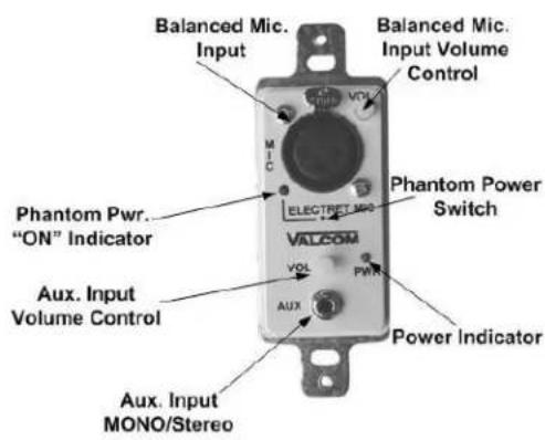
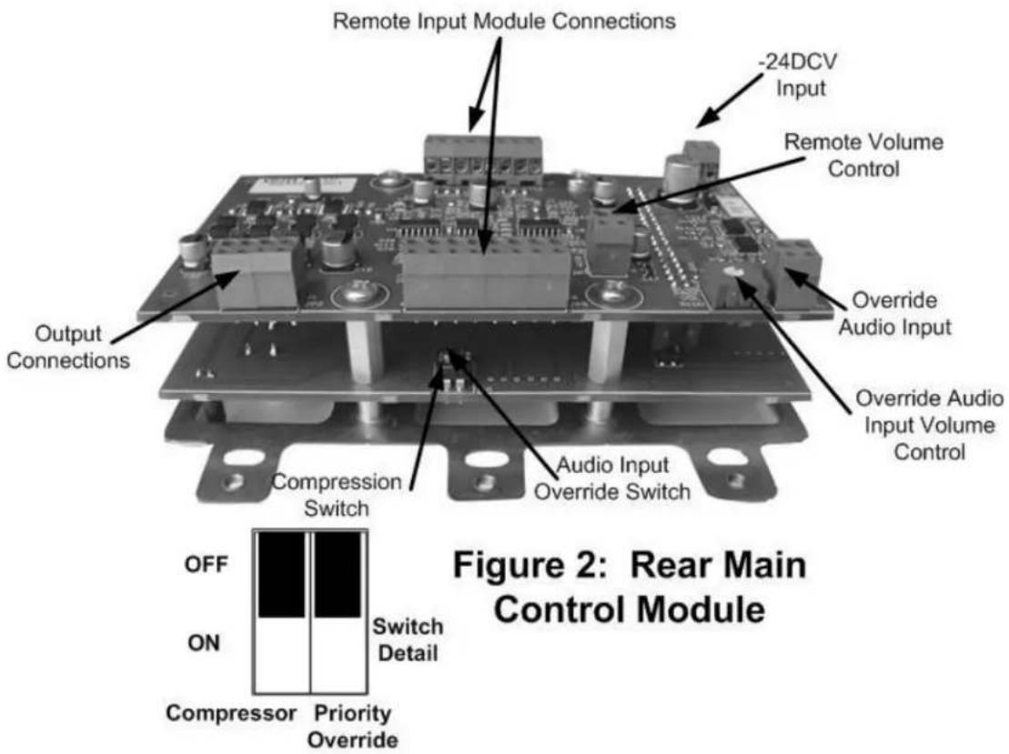
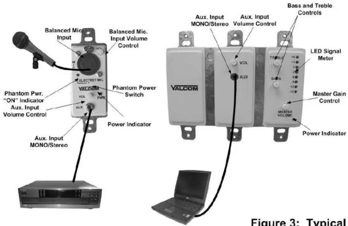
Figure 1 shows volume control locations, microphone and auxiliary input connections. Figure 2 shows output terminal strips and switches on the back of the mixer. Figure 3 shows a typical connecting arrangement. The V-9985 contains a Main Mixer Module and 1 Remote Module. Three additional remote modules may be connected to the main mixer module. Figure 4 shows other feature connections. Figure 5 shows Remote Input Module, Speaker and Power Connections.
All connections should be made to the mixer and double-checked prior to connecting DC power.
Connect the microphone to balanced XLR cables and the microphone XLR connector on the Remote Input Module. If the microphone is a condenser type it will require Phantom Power. Turn "ON" the Phantom Power Switch located on the Remote Module using a small scribe or paper clip. The Phantom Power LED will illuminate. The microphone volume control is located on the remote module. Other sources such as CD and MP3 players, tuners, and computer sound cards may be connected to the auxiliary inputs located on the remote and main modules. Volume controls for the auxiliary inputs are located on the remote input and main control module.
An additional audio input is available with a volume control located on the PC board for connection to a low level audio source such as a telephone page port or Valcom One-Way Page Control. An option dip switch located on the PC board enables the input to override the microphone and auxiliary inputs.
A compressor is available to even out a user's voice to compensate for poor microphone or vocal technique and allow more microphone gain before feedback. All auxiliary and microphone inputs are routed through the compressor when enabled. An option dip switch located on the PC board enables the compressor.
A connection is provided to add a remote volume control. This is a 2 wire connection using a 10K Ohm linear potentiometer.
Speaker Connections
Connect Tip and Ring of Valcom Amplified Speakers to the output screw terminals located on the Main Mixer Module. Connect Tip and Ring of Valcom Amplified Paging Horns to horn audio output screw terminals.
When setting the system up, it is recommended that the master gain control be set 2/3 and aux volume controls be set to 1/4.
OPERATION
The V-9985, Four Channel Pre-Amp/Mixer actively mixes any signals present on the inputs. Each input is equipped with its own volume control to allow blending of the input sources. The unit also has a master volume control to allow a volume level adjustment of all mixed signals. Bass and treble controls allow up to 12dB of boost or cut at 50Hz and 10kHz.
An audio input is available on the main control module allowing connection of a low level signal that will override all other inputs. An option dip switch controls the override feature.
The integrated compressor feature is controlled by an option dip switch. Microphone and auxiliary inputs are routed through the compressor when the compressor is active.
Two outputs are provided by the V-9985 modular mixer.
- An output to drive full range speakers
- An output to drive limited range paging horns
TECHNICAL ASSISTANCE
When trouble is reported, verify there are no broken connections. Assistance in troubleshooting is available from the factory. Call (540) 563-2000 and press 1 for Technical Support, or visit our website at http://www.valcom.com.
Valcom equipment is not field repairable. Valcom, Inc. maintains service facilities in Roanoke, VA. Should repairs be necessary, attach a tag to the unit clearly stating company name, address, phone number, contact person and nature of the problem. Send the unit to:
Valcom, Inc.
Repair & Return Dept.
5614 Hollins Road
Roanoke, VA 24019-5056
VALCOM LIMITED WARRANTY
Valcom, Inc. warrants its products to be free from defects in materials and workmanship under conditions of normal use and service for a period of one year from the date of shipment. The obligation under this warranty shall be limited to the replacement, repair or refund of any such defective device within the warranty period, provided that:
- inspection by Valcom, Inc. indicates the validity of the claim;
- the defect is not the result of damage, misuse or negligence after the original shipment;
- the product has not been altered in any way or repaired by others and that factory sealed units are unopened (a service charge plus parts and labor will be applied to units defaced or physically damaged);
- freight charges for the return of products to Valcom are prepaid;
- all units 'out of warranty' are subject to a service charge. The service charge will cover minor repairs (major repairs will be subject to additional charges for parts and labor).
This warranty is in lieu of and excludes all other warranties, expressed or implied and in no event shall Valcom, Inc. be liable for any anticipated profits, consequential damages, loss of time or other losses incurred by the buyer in connection with the purchase, operation or use of the product.
This warranty specifically excludes damage incurred in shipment. In the event a product is received in damaged condition, the carrier should be notified immediately. Claims for such damage should be filed with the carrier involved in accordance with the F.O.B. point.
Headquarters:
Valcom, Inc.
5614 Hollins Road
Roanoke, VA 24019-5056
Phone: (540) 563-2000
FAX: (540) 362-9800
REMOTE INPUT MODULE
MAIN CONTROL MODULE
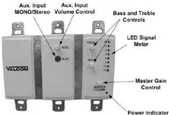
Figure 1: Main and Remote Mixer Front Layout
REMOTE INPUT MODULE
MAIN CONTROL MODULE
Figure 3: Typical Connections
![graph TD A["Valcom One-Way Page Control"] --> B["1: Modular Preamp Mixer"] B --> C["2: Modular Preamp Mixer"] C --> D["X: Modular Preamp Mixer"] B --> E["Page Output"] C --> F["Page Output"] B --> G["Remote Volume Control Input"] C --> H["Override Aud. Port"] D --> I["Page Output"] G --> J["10K Remo…](/content/2026/05/1087460/images/e50000e826133bd7197abec9854d0c77924a8c2979b1d6f3d5a1d27c9799f542.jpg)


- V-9983 2 CHANNEL MODULAR PRE-AMP/MIXER V-9984 REMOTE INPUT MODULE V-9985 4 CHANNEL MODULAR PRE-AMP/MIXER
- INTRODUCTION
- APPLICATIONS
- FEATURES
- MAIN CONTROL MODULE V-9983
- MAIN CONTROL MODULE WITH REMOTE INPUT MODULE
- REMOTE INPUT MODULE V-9984
- DIMENSIONS
- MAIN CONTROL MODULE
- REMOTE INPUT MODULE
- SPECIFICATIONS OUTPUTS
- TONE CONTROLS
- SIGNAL TO NOISE
- AUXILIARY INPUT SENSITIVITY
- BLDG PAGE INPUT SENSITIVITY
- SIGNAL METER
- REMOTE VOLUME CONTROL
- POWER REQUIREMENTS
- REMOTE MODULE
- MICROPHONE INPUT
- PHANTOM POWER
- ENVIRONMENT
- INSTALLATION
- SPEAKER CONNECTIONS
- OPERATION
- TECHNICAL ASSISTANCE
- VALCOM LIMITED WARRANTY
Brand : Valcom
Model : V-9983
Category : Blender